finite element analysis and neutron … · analitical model for prediction of the thermal pta...
TRANSCRIPT

FINITE ELEMENT ANALYSIS AND NEUTRON DIFFRACTION EVALUATION OF RESIDUAL STRESSES IN STELLITE COATING
PRODUCED BY PTA PROCESS
A. Nady1, H.Bonnefoy1, V. KloseK2, M. H. Mathon2, A. Lodini1 and A. Baczmanski3
1UFR Sciences Exactes et Naturelles, LACM, B.P 1039, 51687 Reims Cedex 2, France 2Laboratoire Léon Brillouin, CEA Saclay, 91191 Gif sur Yvette, France
3Faculty of Physics and Applied Computer Science, AGH-University of Science and Technology, al. Mickiewicza 30, 30-059 Kraków, Poland
ABSTRACT
A grade 6 cobalt-based superalloy was coated on steel substrate by the Plasma Transferred Arc (PTA) method. The macrostructure and microstructure of the interface and of the Co-based superalloy layers are studied. A numerical analysis has been carried out to simulate the PTA deposition with physical conditions and mechanical properties using the Abaqus code. A simplified model based on energy conservation and wall functions is used to predict the process, solid shield and shroud on the temperature and the residual stress of the PTA technology at the surface of coating layer and the interface. The results reveal that the residual stress obtained by the numerical simulation are in very good agreement with experimental results performed by the neutron diffraction.
INTRODUCTION
The increasing competition in technological performance encourages further research relating high performance products with reduced manufacturing costs. These aims sometimes call existing knowledge into question and encourage research into new materials and/or new processes. In many industrial applications such as forging, tools are subjected to very severe thermal, mechanical and tribological stresses. Interaction between these factors generally results in damage to the tools. Several combinations of processes and materials are used to reduce the various damage modes. Conventional processes for surface properties modification are the subjects of widespread studies. Research projects combining cobalt-based superalloys by Plasma Transferred Arc (PTA) [1-2] processes are under way. The coatings obtained by these methods exhibit good wear resistance.
454Copyright ©JCPDS-International Centre for Diffraction Data 2009 ISSN 1097-0002Advances in X-ray Analysis, Volume 52

This document was presented at the Denver X-ray Conference (DXC) on Applications of X-ray Analysis. Sponsored by the International Centre for Diffraction Data (ICDD). This document is provided by ICDD in cooperation with the authors and presenters of the DXC for the express purpose of educating the scientific community. All copyrights for the document are retained by ICDD. Usage is restricted for the purposes of education and scientific research. DXC Website – www.dxcicdd.com
ICDD Website - www.icdd.com
Advances in X-ray Analysis, Volume 52

Plasma Transferred Arc process is used to fuse a metallic coating to a substrate in order to improve its resistance against wear and/or corrosion. During the process, metal powder is fed into a molten weld puddle (fusion bath) generated by the plasma transferred arc at high temperature. All welding parameters, including powder feed; power input, plasma gas and shielding gas, as well as torch and workpiece movement are controlled in PLASMA TEAM equipment. The high localized temperature and pressure due to the dynamics of the process, and the localised plastic flow at the welded interface allow strong interface bond. The parameters of the PTA process, the mechanical properties of the obtained coated layer and the relation between them are recent areas under the research [3, 4]. Research shows that the mechanical properties can be strongly linked to the microstructure and the phases formed by local fusion at the interface. This paper presents the investigations of cobalt based superalloy coating on steel substrate by PTA process. These investigations focus on the interface between the two materials. Macrostructure is studied in detail. The thermal impact before (PTA process) is presented.
SAMPLE PREPARATION
The stellite 6 alloy was deposited on to steel using the PTA process. The deposition conditions for the PTA welding used in this study are listed in Table 1. The operating principle of PTA melting used is schematically shown in Figure 1.
Table 1. Experimental conditions for PTA hardfacing Parameters Hardfacing conditions of satellite 6 alloys Torch gap (mm) 10 Plasma gas Ar Carrier gas Ar Powder gas flow (g/min) 45 Main arc current (A) 195 Voltage (V) 29-30 Travel speed rate (mm/min) 40 Nozzle size (mm) 2.2 W electrode size 4.8
Figure 1. Scheme of the PTA system
455Copyright ©JCPDS-International Centre for Diffraction Data 2009 ISSN 1097-0002Advances in X-ray Analysis, Volume 52

The metal powders injected from a powder feeder are melted in the interior of plasma arc flame and then the melted alloy is deposited on the surface of base metal. The stellite 6 alloy powder used in this study has an average diameter of 163 µm (Deloro Co.). The nominal
composition of stellite 6 alloy and steel substrate are given in Table 2. Table 2. Nominal composition of Co-base alloys and steel substrate (wt.%) C Si Mn P S Cr Ni Fe W Mo Co Steel 0.08 1.0 2.0 0.045 0.03 18.0-20.0 8.0-10.5 Bal - - - Stellite 6 1.1 2.0 2.0 - - 30.0 3.0 3.0 4.5 1.5 Bal
ANALITICAL MODEL FOR PREDICTION OF THE THERMAL PTA PROCESS
The fundamental governing equations for the computation are a series of transport equations previously described in detail [5]. In terms of physical modelling, the plasma�air jet is treated as a compressible, turbulent flow with heat exchange taking place during mixing with the air. The quadratic k�å turbulence model is used as a closure. The physical parameters, such as density, viscosity, specific heat coefficient and thermal conductivity of the mixture, can then be determined from the constitutional components, which are known as functions of temperature. The transport equations for the plasma�air jet flow considered here can be written in a general form as: ߲߲ݐ ሺߩϕሻ + ∇. ൫ߩ ሬܷሬԦ߶ − Ãథ∇ம൯ = ܵథ (1)
Where for the continuity equation: Ô=1; for momentum equations: Ô denotes the velocity components U, V or W in the x, y or z directions; for the k and å equations: Ô=k and å,
respectively. In these relationships, ñ, k and å denote the density, turbulent energy and its
dissipation rate, respectively. In addition, UሬሬԦ = UýԦ+ VଌԦ+ WkሬԦ with ýԦ, ଌԦ, kሬԦ denoting the unit vectors in the x, y, z directions, Ã is the coefficient for the diffusion F term associated with Ô
and S is the source term. For the continuity equation: Ã = 1; for the momentum equation in the x, y, z directions:Ã =൫ì + ì୲൯U, ൫ì + ì୲൯V, ൫ì + ì୲൯W ; for the turbulence equation:Ã = ì + ì୲ ó୩Τ ; for the turbulence dissipation rate equation: Ã = ì + ì୲ óகΤ . The viscosity and turbulence viscosity are here represented by ì and ì୲ , respectively, and óகdenotes the standard deviation of å. The fundamental procedure in the finite-volume (FV) method is to integrate the first term of Eq. (1) over a small control volume Ù.
ଵܶ = ݐ߲߲ නߩ߶݀Ù ≈Ù ሺߩ߶Ùሻ − ሺߩ߶Ùሻ∆ݐ (2)
456Copyright ©JCPDS-International Centre for Diffraction Data 2009 ISSN 1097-0002Advances in X-ray Analysis, Volume 52
FINITE ELEMENT MODEL
Initial conditions
The finite element model will take into account the differential contraction between substrate and coating during the cooling process. These kind of residual stresses are produced by so called secondary cooling, as in the Verbeek [6,7] theoretical model. Table 3 presents the properties of the metallic substrate and stellite 6 material. As one can see, there exists a mismatch between the thermal expansion coefficients that leads to residual stress during the cooling of the materials from plasma thermal spraying process temperature. The difference between the elastic properties of these materials is another source of residual stress (the Young�s modulus is three times higher for substrate).
Table 3. Properties of the steel substrate and stellite 6 material. _____________________________________________________________ Physical properties Steel Stellite 6 _____________________________________________________________ Density (kgm-3) 7827 7800 Thermal conductivity (Wm-1K-1) 46.6 55 Heat capacity (Jkg-1K-1) 580 456 Young�s modulus (10
9 Pa) 210 195 Poisson ratio 0.277 0.21 Thermal expansion coefficient (10-6 K-1) 12.5 6.6 _____________________________________________________________ Modelling
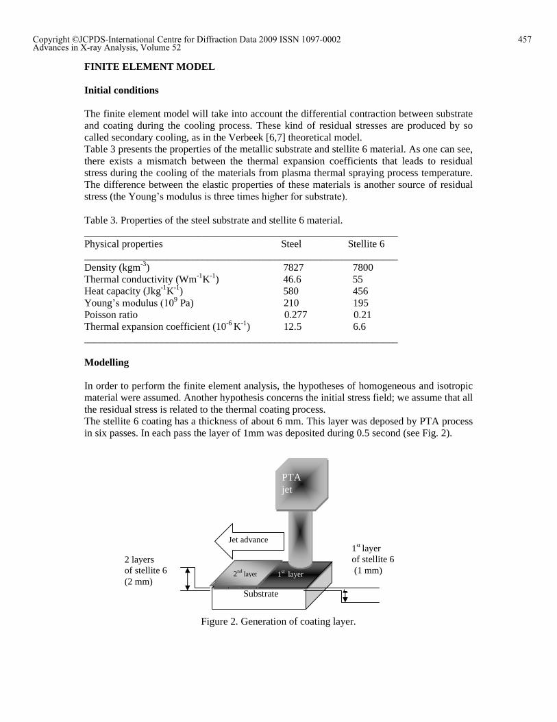
In order to perform the finite element analysis, the hypotheses of homogeneous and isotropic material were assumed. Another hypothesis concerns the initial stress field; we assume that all the residual stress is related to the thermal coating process. The stellite 6 coating has a thickness of about 6 mm. This layer was deposed by PTA process in six passes. In each pass the layer of 1mm was deposited during 0.5 second (see Fig. 2).
Figure 2. Generation of coating layer.
2 layers of stellite 6 (2 mm)
1st layer of stellite 6 (1 mm)
Substrate
1st layer 2nd layer
PTA jet
Jet advance
457Copyright ©JCPDS-International Centre for Diffraction Data 2009 ISSN 1097-0002Advances in X-ray Analysis, Volume 52

In order to determine the residual stress generated in the metallic substrate and in the deposited stellite 6, each individual layer on the cold substrate while the next layers are deposited over the ptemperature field during deposition calculated accordingly. It is assumed thashould determine if the calculated residual strthan the ultimate tensile strength for this material.
Figure
Finite Element Mesh
Entities Mode of filling
Substrate Cut base material (structured)
Coating Cut material deposited (structured)
CPS4R A 4-node bilinear plane stress quadrilateral, reduced integration, hourglass control.
Figure 4
In order to determine the residual stress generated in the metallic substrate and in the each individual layer is considered separately. The first layer is deposited
on the cold substrate while the next layers are deposited over the previous warm layersduring deposition is calculated (Fig. 3) and the stress distribution is then
calculated accordingly. It is assumed that each layer is deposed at 1800 K. should determine if the calculated residual stress in the individual satellite 6 layers is greater than the ultimate tensile strength for this material.
Figure 3: Thermal history during the PTA process
Element shape Number of element
Type of element
Quad-dominated 7768 CPS4R
Quad 1000 CPS4R
node bilinear plane stress quadrilateral, reduced integration, hourglass
Figure 4: Finite element mesh of the sample
In order to determine the residual stress generated in the metallic substrate and in the considered separately. The first layer is deposited
revious warm layers. The and the stress distribution is then
The analysis layers is greater
Type of element CPS4R
CPS4R
node bilinear plane stress quadrilateral, reduced integration, hourglass
458Copyright ©JCPDS-International Centre for Diffraction Data 2009 ISSN 1097-0002Advances in X-ray Analysis, Volume 52

The hard-facing material is stellite 6 alloy and the base metal was a type of steel, 55NCDV7. Reduced integration and hour-glass control were used in the residual stress analysis. The finite element mesh of the sample is shown in Fig. 4.
DIFFRACTION MEASUREMENTS
To validate the mathematical model, a neutron diffraction experiment was performed on the G5.2 spectrometer at the Orphee facility of the Laboratoire Leon Brillouin, Saclay, France. The measurements were carried out on the sample of dimension 20x15x10 mm3, using the gauge volume of 1x1x5 mm3 (Fig. 5). The lattice strains in two directions (x and y in Fig. 5) were determined for different depths below the sample surface. An incident neutron wavelength of 2.57 Å, was applied, to give scattering angles from the (111) peaks at about ~88°, both for the substrate and for the coating. The stress free interplanar spacing, were measured using two additional small samples entirely immersed in the neutron beam (these samples were cut from the coating and from the substrate and they had the same dimension as the gauge volume). The principal stresses were determined using the elastic constants given in Table 3.
Figure 5. Orientations of the scattering vector with respect to the sample during neutron diffraction measurements. The sample coordinates system xyz is shown.
RESULTS AND DISCUSSION
Coating microstructure The optical micrographs across the cross section of the steel and stellite-6 coating are shown in Fig. 6. The microstructure of the coating is uniform, dense and layered. Stellite-6 coating has an ordered and granular structure. The oxide inclusion and porosity can be seen in both structures. One can see carbides of type M6C mainly due to the presence of tungsten. The optical micrograph shows the grain structure of the superalloy. Precipitation in carbide of chromium can also be seen at grain boundaries. In Fig. 6 the average diffractogram of a heterogeneous zone is shown.
459Copyright ©JCPDS-International Centre for Diffraction Data 2009 ISSN 1097-0002Advances in X-ray Analysis, Volume 52

Figure 6. Optical micrograph along the cross section and X-ray diffraction patterns taken from the surface of stellite 6 hard-facing alloys.
Residual stresses The residual stress distributions along the depth on the top surface and through the thickness are shown in Fig. 7. The hard-facing layer is subjected to a tensile residual stress and a compressive residual stress. The residual stress in this layer is small. For the base metal, the residual stress is compressive in the part close to the hard-facing layer, whilst it changes from compressive to tensile, and then compressive again for positions away from the hard-facing layer. When the hard-facing layer was cooled from its solidus temperature to room temperature, its contraction in x and y directions were restrained with two parts of metal, one being the base metal under it and the inner part of the layer. These two restraining effects led to the layer being subjected to compressive residual stress in the x and y direction. The shrinking of the hard-facing layer was mainly hindered by the internal metal in it; consequently, a tensile residual stress was present in the layer at the surface and in the base metal at some distance from the hard-facing layer. In the practical hard-facing of a sample, it was found that the cracks occurred just at the hard-facing process. This demonstrated indirectly that the tensile residual stress was the main factor inducing the fracture on the layer. The residual stress test also showed that the residual stresses changed from compressive to tensile in the coating as well as in the base material.
Figure 7. Residual stress components obtained by FEA and neutron diffraction
460Copyright ©JCPDS-International Centre for Diffraction Data 2009 ISSN 1097-0002Advances in X-ray Analysis, Volume 52

CONCLUSIONS
In this paper, the residual stresses in the hard-facing layer were investigated using a numerical simulation method with the aid of the commercial software ABAQUS and the neutron diffraction. The following conclusions were drawn: The residual stresses given by the numerical simulation are in very good agreement
with the experimental results obtained by neutron diffraction and analytical evaluation, in the substrate and are quite acceptable for the coating.
The tensile stress levels obtained in the stellite 6 layer may be explained by the very high cooling rates applied during the deposition process.
The finite element model is validated, through the good agreement between measured stresses and calculated values in the metallic substrate.
This model is a useful instrument for residual stress prediction in stellite 6 coating deposited using PTA process. The direct measurement of these stresses is time consuming, due to the specific morphology of the coating.
During the PTA process significant stresses generated initializing cracks in the interface.
REFERENCES [1] Q.Y.Hou, J.S.Gao,F.Zhou, Surface and Coatings Technology, 2005, 194, 238-243. [2] J.N.Aoh, J.C.Chen,Wear, 2001, 250, 611-620. [3] Y.Li, H, Hashimoto, E. Sukedai, Y. Zhang and Z. Zhang, Journal of Electron Microscopy,
2005, 49, 5. [4] L.E. Murr, C.S.Niou, E.P.Garcia, E. T. Ferreyra, J.M.Rivas, J.C.Sanchez, Materials
Science and Engineering A, 1997, 222, 118-132. [5] B. Liu, T. Zhang, D.T. Gawne, Surf. Coat. Technol., 2000,132, 202-216 [6] P. Fogarassy, F.Turquier, A. Lodini, Residual stress in plasma sprayed zirconia on
cylindrical components Mechanics of Materials, 2003, 35, 633�640. [7] Verbeek, A.T.J., 1991. Plasma Sprayed Thermal Barrier Coatings: Production,
Characterisation and Testing, Ph.D. Thesis. Eindhoven University of Technology, Eindhoven, The Netherlands ,1991, 76-80.
461Copyright ©JCPDS-International Centre for Diffraction Data 2009 ISSN 1097-0002Advances in X-ray Analysis, Volume 52