finite element analysis of 3-1/8” and 4-1/16” 5ksi api 6b
TRANSCRIPT

FINITE ELEMENT ANALYSISOF 3-1/8” AND 4-1/16” 5KSI API 6BFLANGES
Prepared ForAmerican Petroleum InstituteWashington, DC
April, 2011
STRESS ENGINEERING SERVICES, INC.Houston, Texas

PN1101084/LR1101084_RevA.doc
FINITE ELEMENT ANALYSIS
OF 3-1/8” AND 4-1/16” 5KSI API 6B FLANGES
PN 1101084, Rev. 0
Prepared forAmerican Petroleum Institute
Washington, DC
Prepared By:__________________________Venkata P. Nadakuditi
Analyst
Prepared By:__________________________Andreas Katsounas, PE
Principal
Reviewed By:__________________________S. Allen Fox, PE
Principal
Stress Engineering Services, Inc.13800 Westfair East Drive
Houston, Texas 77041-1101
Texas Registered Engineering Firm F-195
APRIL, 2011

APIFinite Element Analysis of 3-1/8” and 4-1/16” 5Ksi API 6B Flanges April, 2011
Stress Engineering Services, Inc. Page 1 Letter Report No. – PN 1101084
LIMITATIONS OF THIS REPORT
The scope of this report is limited to the matters expressly covered. This report is prepared for
the sole benefit of the American Petroleum Institute, Washington, DC. In preparing this report,
Stress Engineering Services, Inc. (SES) has relied on information provided by American
Petroleum Institute, Washington, DC. Stress Engineering Services, Inc. (SES) has made no
independent investigation as to the accuracy or completeness of such information and has
assumed that such information was accurate and complete. Further, Stress Engineering Services,
Inc. (SES) is not able to direct or control the operation or maintenance of client’s equipment or
processes.
All recommendations, findings and conclusions stated in this report are based upon facts and
circumstances, as they existed at the time that this report was prepared. A change in any fact or
circumstance upon which this report is based may adversely affect the recommendations,
findings, and conclusions expressed in this report.
NO IMPLIED WARRANTY OF MERCHANTABILITY OR FITNESS FOR A PARTICULARPURPOSE SHALL APPLY. STRESS ENGINEERING SERVICES, INC. MAKES NOREPRESENTATION OR WARRANTY THAT THE IMPLEMENTATION OR USE OF THERECOMMENDATIONS, FINDINGS, OR CONCLUSIONS OF THIS REPORT WILLRESULT IN COMPLIANCE WITH APPLICABLE LAWS OR PERFECT RESULTS.

APIFinite Element Analysis of 3-1/8” and 4-1/16” 5Ksi API 6B Flanges April, 2011
Stress Engineering Services, Inc. Page 2 Letter Report No. – PN 1101084
FINITE ELEMENT ANALYSIS OF 3-1/8” AND 4-1/16” 5KSI API 6B FLANGES
SUMMARY
Stress Engineering Services (SES) performed elastic three-dimensional (3D) finiteelement analysis of the 3-1/8” and 4-1/16” 5ksi API 6B flange connectors undercombined loading to determine the API Bulletin 6AF and 6AF2 type load rating charts.The load combinations and allowable stress and leakage criteria, defined in APIcontracts PRAC 86-21 (resulting in API Bulletin 6AF through axisymmetric analyses)and PRAC 88-21 (resulting in API Bulletin 6AF2 through 3D analyses), were used togenerate the load rating charts. At the request of API, the flanges were not evaluatedfor thermal effects of 250°F internal and 30°F external temperature differential. Theapplied loads were bolt preload, tension, bore pressure, and bending moment. Thisreport describes the analytical work performed by SES.
The 3D half-symmetry analysis model of one side of the flange connector consisted of8-noded solid elements for both the flange and the bolts. The linear elastic analysiswas performed with the ABAQUS general purpose analysis program. The gasket wasnot modeled, but rather a circumferential line of nodes along the gasket groove wasaxially restrained. Symmetry boundary condition were applied at the flange and boltsymmetry planes.
The models were subjected to four individual unit loads; 52.5ksi bolt makeup, 1000psibore pressure with the associated pressure end load, tension of 10000psi axial pipestress, and bending moment that resulted in 10000psi stress at the extreme fiber of thepipe. The last three loads were applied without any initial makeup load in the bolts.
The analysis results were post-processed to obtain unit load linearized stresscomponents for limiting cross sections in the hub and flange, and to obtain unit bolt andgasket loads. The stress components were combined for each desired loadcombination and compared against the allowable stress and sealability criteria for52.5ksi and 40ksi bolt preloads.
Two different types of rating charts are provided (see Attachment C-2). The API 6AF(PRAC 86-21) type rating chart shows (in a single plot, see Figures 2 for 3-1/8” andFigure 6 for 4-1/16”) the controlling curves for all criteria. The API 6AF2 (PRAC 88-21)type rating charts show the curves based on the sealability criteria, and the stresscriteria (hub, flange, bolt) in separate plots (see Figures 3 and 4 for 3-1/8” and Figures 7and 8 for 4-1/16”). The hub pipe body section controlled the stress criteria.

APIFinite Element Analysis of 3-1/8” and 4-1/16” 5Ksi API 6B Flanges April, 2011
Stress Engineering Services, Inc. Page 3 Letter Report No. – PN 1101084
INTRODUCTION
The objective of this work was to evaluate the load carrying capacity of the 3-1/8” and 4-1/16” 5ksi API 6B flange connectors and generate rating charts in the same format asAPI Bulleting 6AF2.
This was accomplished using and 3D linear elastic finite element analysis using thesame load combinations, allowable stress criteria and leakage criteria defined in APIcontracts PRAC 86-21 (resulting in API Bulletin 6AF through axisymmetric analyses)and PRAC 88-21 (resulting in API Bulletin 6AF2 through 3D analyses). At the requestof API, the flanges were not evaluated for thermal effects of 250°F internal and 30°Fexternal temperature differential. The applied loads were bolt preload, tension, borepressure, and bending moment.
METHOD OF ANALYSIS
Three-dimensional linear elastic finite element analysis was used to determine thestresses and loads in the flange connections. The ABAQUS general purpose finiteelement program Version 6.5 was used.
To ensure linear behavior (similar to API 6AF and 6AF2) the gasket was not modeledand the bolt head nodes were tied to the corresponding flange nodes.
Description of Geometry
The geometry of the 3-1/8” and 4-1/16” 5ksi API 6B flange connectors was based onAPI 6A Nineteenth Edition (July 2004). The basic minor diameter of the bolt was used.
Description of Model
The analysis models were generated in PATRAN and then converted to ABAQUS inputformat. Solid elements, ABAQUS C3D8 were used for the analysis. These 8-node solidelements were used to model the flange and the bolts. The element mesh density (seeFigure 1 for 3-1/8” and Figure 5 for 4-1/16”) was finer than the typical mesh densityused in API 6AF2.
The gasket was not modeled, but rather a circumferential line of nodes along the gasketgroove was axially restrained. These were the nodes on the outer diameter of thebottom of the groove. Symmetry boundary condition were applied at the flange and boltsymmetry planes. Symmetry boundary condition was used at the XY plane of flangesymmetry and the two half bolts. Symmetry boundary condition was also used at theXZ plane of symmetry of the bolts.
The bolt nut or bolt head nodes were tied to the corresponding nodes of the flange.
The hub (pipe body) was extended for a sufficient distance (2 diameters) beyond thediscontinuity in order to avoid end effects. This was greater than the minimum requireddistance 2.5*sqrt(rt), where r is the radius and t is the wall thickness of the hub end.

APIFinite Element Analysis of 3-1/8” and 4-1/16” 5Ksi API 6B Flanges April, 2011
Stress Engineering Services, Inc. Page 4 Letter Report No. – PN 1101084
The bending moment load was transferred to the hub end section through an ABAQUS*KINEMATIC COUPLING definition relating the degrees of freedom of a referencednode to the nodes of the hub end. The bolt preload was applied using an ABAQUS*PRETENSION definition.
Mesh plots are provided in Figures 1 and 5, and Attachment B.
Assumptions
The assumptions were identical to the API 6AF2 assumptions. Selected assumptionsare provided below:
- the elastic material was represented by 29000ksi modulus of elasticity and 0.3Poisson’s ratio,
- the bending moment was applied as a bending moment load and not as astress. The applied bending moment for the 3-1/8” flange was 10163ft-lbs andfor the 4-1/16” flange was 16943ft-lbs, which resulted in 10000psi stress at theextreme fiber of the hub,
- for post-processing purposes the yield strength of the flanges at operating andtest conditions was 60ksi, and for the bolts the yield strength was either 105ksi or80ksi.
Load Cases
The model was subjected to four individual unit loads; 52.5ksi bolt makeup, 1000psibore pressure with the associated pressure end load, tension of 10000psi axial pipestress, and bending moment that resulted in 10000psi stress at the extreme fiber of thepipe. The last three loads were applied without any initial makeup load in the bolts.
For makeup the applied load in each bolt was:
41499lbs (20750bs for the half bolts) corresponding to 52.5ksi giving a total boltload of 332kips for the 8 bolts for the 3-1/8” flange
52484lbs (26242lbs for the half bolts) corresponding to 52.5ksi giving a total boltload of 420kips for the 8 bolts for the 4-1/16” flange
The applied bore pressure was 1000psi. The pressure was applied along the bore andto the face of the flange up to the seal groove outside diameter (API 6A “G” dimension).The corresponding pressure end load of 8143lbs or 603psi pressure was applied at thehub end for the 3-1/8” flange. For the 4-1/16” flange the pressure end load was14387lbs or 818psi pressure
The applied tension load was 135042lbs for the 3-1/8” flange, and 175819lbs for the 4-1/16” flange corresponding to 10000psi hub end pressure.
The applied bending moment was 10163 ft-lbs for the 3-1/8” flange, and 16943 ft-lbs forthe 4-1/16” flange, which resulted in 10000psi stress at the extreme fiber of the hub.

APIFinite Element Analysis of 3-1/8” and 4-1/16” 5Ksi API 6B Flanges April, 2011
Stress Engineering Services, Inc. Page 5 Letter Report No. – PN 1101084
Linearized Stresses
The stresses given by the elastic finite element solutions contain peak as well asmembrane and bending stresses. The membrane and membrane plus bendingstresses are obtained by determining the linear, statically-equivalent stress distributionacross a section for each stress component, referred to as "linearized stresses." This isaccomplished by calculating the surface bending and average stress for a lineardistribution that has the same first moment and the same resultant as the actual stressdistribution. The ABAQUS linearization routine was used.
The stresses were linearized along 4 cross-sections in the symmetry plane on thetension side of bending (see Figure 1 and 5). Note that the corresponding sections onthe compression side of bending were also considered in the post-processing programby reversing the sign of the stresses for the bending load.
Leakage Criterion
Leakage was assumed to occur when the compressive reaction force due to makeup, atthe gasket node on the tension side of bending, was equal to the sum of the tensilereaction loads from pressure, tension, and bending moment loads. This is aconservative assumption since it neglects the gasket’s ability to work as a pressure-energized seal, but is the same assumption made for API 6AF and 6AF2.
Stress Criteria
The stress criteria for the hub, flange and bolt are the same criteria used for API 6AFand 6AF2, which were based on ASME code stress categories using the basicallowable membrane stress intensities defined by API 6A.
The basic allowable membrane stress intensity is defined in API 6A as:
€
Sm = 2 3Sy
where, Sm is the design stress intensity at rated working pressure, and Sy is theminimum specified yield strength in the flange/hub.
The allowable stress intensity for hydrostatic pressure testing is:
€
ST = 0.83Sy
where, ST is the general primary membrane stress intensity at hydrostatic testpressure in the flange/hub.
The allowable tensile stress in the closure bolting is:
€
SA = 0.83Sy

APIFinite Element Analysis of 3-1/8” and 4-1/16” 5Ksi API 6B Flanges April, 2011
Stress Engineering Services, Inc. Page 6 Letter Report No. – PN 1101084
where, SA is the maximum membrane stress in the bolting for all loads, and Sy isthe specified minimum yield strength of bolting. This allowable is applied only tomembrane stress since bolt bending stresses are ignored.
The basic allowable stresses as well the classification of stresses into primary andsecondary stresses (for each cross-section) form the basis for establishing stress limitsfor selected load combinations. Attachment A provides excerpts from the SES report(PRAC 86-21) and from API 6AF2 (PRAC 88-21) on the load conditions, classificationand allowable stresses.
Stresses due to makeup only are classified as primary stresses at all sections.Stresses due to hydrostatic test pressure only are also classified as primary stressesusing the increased allowable specified for this case. Stresses due to makeup with testpressure is considered to be a primary stress in flange sections (with the increasedallowable), but is considered a secondary stress in all other sections. Stress due to anycombination of tension, working pressure, and moment is a primary stress at allsections. In flange sections, makeup added to pressure, tension and moment is aprimary stress. However, this is a secondary stress at the hub sections.
Load Rating Methodology
The post-processing program developed for PRAC 86-21 was modified from processingfour stress components (for axisymmetric analysis) to six stress components (for 3Danalysis). The program automated the calculation of bending moment capacities atvarious tension and pressure combinations for each makeup condition (52.5ksi and40ksi). The program combined unit load linearized stress components to compareagainst the allowable values reporting also the controlling section. The programcombined unit load gasket and bolt load results to check leakage (zero gasket load) andbolt stresses against bolt allowable stresses.
The component stresses were combined to stress intensity values rather than the vonMises stresses. The ASME code is based on the maximum shear stress theory offailure, which is more conservative than the distortion energy theory.
Two different types of rating charts are provided. The API 6AF (PRAC 86-21) typerating chart shows (in a single plot) the controlling curves for all criteria. The API 6AF2(PRAC 88-21) type rating chart shows the curves based on the stress criteria (hub,flange, bolt) and the curves based on the sealability criteria in separate plots.

APIFinite Element Analysis of 3-1/8” and 4-1/16” 5Ksi API 6B Flanges April, 2011
Stress Engineering Services, Inc. Page 7 Letter Report No. – PN 1101084
ANALYSIS RESULTS
Analysis results are summarized in the form of load combination rating charts, which arethe deliverables of this work (see Attachments C-2 and D-2). The load rating chart forthe combined leakage and stress criteria (API 6AF type) is provided in Figures 2 and 6.The load rating charts for the leakage and stress criteria separately (API 6AF2 type) areprovided in Figures 3, and 4, respectively for the 3-1/8” flange and Figures 7, and 8,respectively for the 4-1/16” flange.
The stress based rating is controlled by the stresses in the hub Section #2 in the tensionside of bending due to the primary loads.
The leakage based rating loads are always lower that the stress based rating loads, butas noted earlier the selected leakage criteria is conservative. In fact this is the reasonthat for API 6AF2 the ratings were published separately for the leakage and stresscriteria.
The bolt allowable stresses did not control any of the rating loads even with the 80ksibolts. Evaluation of cross-sections and loads at the sealing nodes on the plane (off thesymmetry plane) between bolts on the tension and compression side of bending hasshown that the stress and loads at the symmetry plane controlled the flange rating.
In addition to the stress criteria of Attachment A, the stress intensity of the combinedstate of stress for selected load combinations was compared to a triaxial stress limit of4*Sm, which was not exceeded. This was checked at the controlling bending momentsof Figures 2 and 6 for zero tension with zero and 5000 psi pressure, and likewise at atension of 200 kips for 3-1/8”, and 240 kips for 4-1/16”.
Stress intensity (TRESCA) contour plots are provided in Attachment C-1 and D-1 foreach of the four load cases. The axial stress (S22) contour plot is provided for thebending moment solution.
A comparison of the results of this analysis to the published data in API TechnicalReport 6AF2 is provided in Attachment E. Based on stress criteria the combined loadcharts predicted by this analysis are higher than the published API TR 6AF2 charts, andbased on leakage criteria the combined load charts predicted by this analysis arealmost the same as the published API TR 6AF2 charts.
ATTACHMENTS
The following attachments are included to support the above results:
Attachment A: Adopted Stress Criteria for API 6AF and 6AF2Attachment B: Analysis ModelsAttachment B-1: Analysis Model - 3-1/8” 5ksi API 6B flangeAttachment B-2: Analysis Model - 4-1/16” 5ksi API 6B flangeAttachment C: Analysis Results for 3-1/8” 5ksi API 6B flange

APIFinite Element Analysis of 3-1/8” and 4-1/16” 5Ksi API 6B Flanges April, 2011
Stress Engineering Services, Inc. Page 8 Letter Report No. – PN 1101084
Attachment C-1: Stress Contour PlotsAttachment C-2: Load Combination Rating ChartsAttachment D: Analysis Results for 4-1/16” 5ksi API 6B flangeAttachment D-1: Stress Contour PlotsAttachment D-2: Load Combination Rating ChartsAttachment E: Comparison of FEA Results to API Technical Report 6AF2
Load Combination Charts

APIFinite Element Analysis of 3-1/8” and 4-1/16” 5Ksi API 6B Flanges April, 2011
Stress Engineering Services, Inc. Page 9 Letter Report No. – PN 1101084
Tension Side of Bending Linearized Section Locations(View of the Symmetry Plane on Tension Side)
FIGURE 1FINITE ELEMENT MODEL – 3-1/8” 5KSI API 6B
1
1 2
3
4
XY SymmetryPlane Boundary
Conditions (uz=0)
XZ SymmetryBoundaryConditions
For Middle ofBolts/Studs (uy=0)
Hub Sections; 1 and 2Flange Sections; 3 and 4
Typical Bolt/Stud
Nodes AroundCircumference
Fixed in theAxial Direction (uy=0)

APIFinite Element Analysis of 3-1/8” and 4-1/16” 5Ksi API 6B Flanges April, 2011
Stress Engineering Services, Inc. Page 10 Letter Report No. – PN 1101084
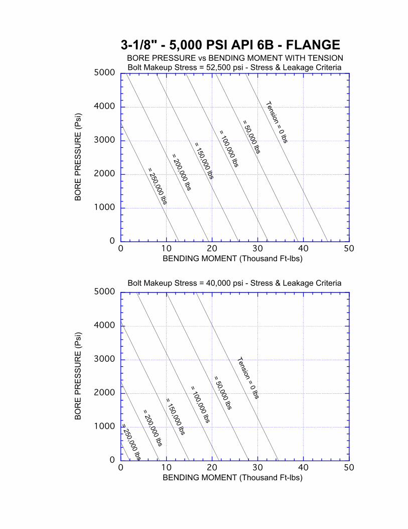
FIGURE 2API 6AF TYPE RATING CHART – 3-1/8” 5KSI API 6B

APIFinite Element Analysis of 3-1/8” and 4-1/16” 5Ksi API 6B Flanges April, 2011
Stress Engineering Services, Inc. Page 11 Letter Report No. – PN 1101084
FIGURE 3API 6AF2 TYPE RATING CHART (LEAKAGE CRITERIA) – 3-1/8” 5KSI API 6B

APIFinite Element Analysis of 3-1/8” and 4-1/16” 5Ksi API 6B Flanges April, 2011
Stress Engineering Services, Inc. Page 12 Letter Report No. – PN 1101084
FIGURE 4API 6AF2 TYPE RATING CHART (STRESS CRITERIA) – 3-1/8” 5KSI API 6B

APIFinite Element Analysis of 3-1/8” and 4-1/16” 5Ksi API 6B Flanges April, 2011
Stress Engineering Services, Inc. Page 13 Letter Report No. – PN 1101084
Tension Side of Bending Linearized Section Locations(View of the Symmetry Plane on Tension Side)
FIGURE 5FINITE ELEMENT MODEL – 4-1/16” 5KSI API 6B
1
1 2
3
4Hub Sections; 1 and 2
Flange Sections; 3 and 4
Typical Bolt/Stud
Nodes AroundCircumference
Fixed in theAxial Direction (uy=0)
XZ SymmetryBoundaryConditions
For Middle ofBolts/Studs (uy=0) XY Symmetry
Plane BoundaryConditions (uz=0)

APIFinite Element Analysis of 3-1/8” and 4-1/16” 5Ksi API 6B Flanges April, 2011
Stress Engineering Services, Inc. Page 14 Letter Report No. – PN 1101084
FIGURE 6API 6AF TYPE RATING CHART – 4-1/16” 5KSI API 6B

APIFinite Element Analysis of 3-1/8” and 4-1/16” 5Ksi API 6B Flanges April, 2011
Stress Engineering Services, Inc. Page 15 Letter Report No. – PN 1101084
FIGURE 7API 6AF2 TYPE RATING CHART (LEAKAGE CRITERIA) – 4-1/16” 5KSI API 6B

APIFinite Element Analysis of 3-1/8” and 4-1/16” 5Ksi API 6B Flanges April, 2011
Stress Engineering Services, Inc. Page 16 Letter Report No. – PN 1101084
FIGURE 8API 6AF2 TYPE RATING CHART (STRESS CRITERIA) – 4-1/16” 5KSI API 6B

APIFinite Element Analysis of 3-1/8” and 4-1/16” 5Ksi API 6B Flanges April, 2011
Stress Engineering Services, Inc. Page 17 Letter Report No. – PN 1101084
REFERENCES
1. “Capabilities of API Flanges Under Combination of Loading PRAC 86-21,”Stress Engineering Services, Prepared for API, October 1987.
2. "Specification for Wellhead and Christmas Tree", API Spec, 19th Edition, July2004.
3. "Technical Report on Capabilities of API Flanges Under Combinations of Load",API 6AF (Formerly Bulletin 6AF), 2nd Edition, September 1995.
4. "Bulletin on Capabilities of API Flanges Under Combinations of Load – Phase II",API TR 6AF2 (Formerly Bulletin 6AF2), 2nd Edition, April 1999.

ATTACHMENT A
ADOPTED STRESS CRITERIA FOR API 6AF AND 6AF2


ATTACHMENT B
ANALYSIS MODELS

ATTACHMENT B-1
ANALYSIS MODEL - 3-1/8” 5KSI API 6B FLANGE

X
YZ

X
YZ

X
Y
Z

X
Y
Z

ATTACHMENT B-2
ANALYSIS MODEL - 4-1/16” 5KSI API 6B FLANGE

X
YZ

X
YZ

X
Y
Z

X
Y
Z

ATTACHMENT C
ANALYSIS RESULTS FOR 3-1/8” 5KSI API 6B FLANGE

ATTACHMENT C-1
STRESS CONTOUR PLOTS

(Avg: 75%)S, Tresca
+3.780e−01+5.000e+03+1.000e+04+1.500e+04+2.000e+04+2.500e+04+3.000e+04+3.500e+04+4.000e+04+4.500e+04+5.000e+04+5.500e+04+6.000e+04+1.352e+05
Step: Step−1, APPLICATION OF MAKE UP LOADIncrement 1: Step Time = 1.000Primary Var: S, TrescaDeformed Var: U Deformation Scale Factor: +1.000e+00X
Y
Z

(Avg: 75%)S, Tresca
+8.599e+01+1.329e+03+2.572e+03+3.814e+03+5.057e+03+6.300e+03+7.543e+03+8.786e+03+1.003e+04+1.127e+04+1.251e+04+1.376e+04+1.500e+04+3.514e+04
Step: Step−1, APPLICATION OF END TENSIONIncrement 1: Step Time = 1.000Primary Var: S, TrescaDeformed Var: U Deformation Scale Factor: +1.000e+00X
Y
Z

(Avg: 75%)S, Tresca
+1.790e+01+4.331e+02+8.482e+02+1.263e+03+1.679e+03+2.094e+03+2.509e+03+2.924e+03+3.339e+03+3.754e+03+4.170e+03+4.585e+03+5.000e+03+6.690e+03
Step: Step−1, APPLICATION OF INTERNAL PRESSUREIncrement 1: Step Time = 1.000Primary Var: S, TrescaDeformed Var: U Deformation Scale Factor: +1.000e+00X
Y
Z

(Avg: 75%)S, Tresca
+3.359e+01+1.281e+03+2.528e+03+3.775e+03+5.022e+03+6.270e+03+7.517e+03+8.764e+03+1.001e+04+1.126e+04+1.251e+04+1.375e+04+1.500e+04+2.016e+04
Step: Step−1, APPLICATION OF BENDING MOMENTIncrement 1: Step Time = 1.000Primary Var: S, TrescaDeformed Var: U Deformation Scale Factor: +1.000e+00X
Y
Z

(Avg: 75%)S, S22
−1.739e+04−1.494e+04−1.249e+04−1.004e+04−7.595e+03−5.146e+03−2.696e+03−2.468e+02+2.203e+03+4.652e+03+7.101e+03+1.000e+04+1.200e+04
−1.739e+04
+1.738e+04
Step: Step−1, APPLICATION OF BENDING MOMENTIncrement 1: Step Time = 1.000Primary Var: S, S22Deformed Var: U Deformation Scale Factor: +1.000e+00X
Y
Z

ATTACHMENT C-2
LOAD COMBINATION RATING CHARTS
0
1000
2000
3000
4000
5000
0 10 20 30 40 50
3-1/8" - 5,000 PSI API 6B - FLANGE
BO
RE
PR
ES
SU
RE
(Psi
)
BENDING MOMENT (Thousand Ft-lbs)
BORE PRESSURE vs BENDING MOMENT WITH TENSIONBolt Makeup Stress = 52,500 psi - Stress & Leakage Criteria
Tension = 0 lbs
= 50,000 lbs
= 100,000 lbs
= 150,000 lbs
= 200,000 lbs
= 250,000 lbs
0
1000
2000
3000
4000
5000
0 10 20 30 40 50
BO
RE
PR
ES
SU
RE
(Psi
)
BENDING MOMENT (Thousand Ft-lbs)
Bolt Makeup Stress = 40,000 psi - Stress & Leakage Criteria
Tension = 0 lbs
= 50,000 lbs
= 100,000 lbs
= 150,000 lbs
= 200,000 lbs
= 250,000 lbs

0
1000
2000
3000
4000
5000
0 10 20 30 40 50
3-1/8" - 5,000 PSI API 6B - FLANGE
BO
RE
PR
ES
SU
RE
(Psi
)
BENDING MOMENT (Thousand Ft-lbs)
BORE PRESSURE vs BENDING MOMENT WITH TENSIONBolt Makeup Stress = 52,500 psi - Leakage Criteria Only
Tension = 0 lbs
= 50,000 lbs
= 100,000 lbs
= 150,000 lbs
= 200,000 lbs
= 250,000 lbs
0
1000
2000
3000
4000
5000
0 10 20 30 40 50
BO
RE
PR
ES
SU
RE
(Psi
)
BENDING MOMENT (Thousand Ft-lbs)
Bolt Makeup Stress = 40,000 psi - Leakage Criteria Only
Tension = 0 lbs
= 50,000 lbs
= 100,000 lbs
= 150,000 lbs
= 200,000 lbs
= 250,000 lbs

0
1000
2000
3000
4000
5000
0 10 20 30 40 50
3-1/8" - 5,000 PSI API 6B - FLANGE
BO
RE
PR
ES
SU
RE
(Psi
)
BENDING MOMENT (Thousand Ft-lbs)
BORE PRESSURE vs BENDING MOMENT WITH TENSIONBolt Makeup Stress = 52,500 psi - Stress Criteria Only
Tension = 0 lbs
= 50,000 lbs
= 100,000 lbs
= 150,000 lbs
= 200,000 lbs
= 250,000 lbs
0
1000
2000
3000
4000
5000
0 10 20 30 40 50
BO
RE
PR
ES
SU
RE
(Psi
)
BENDING MOMENT (Thousand Ft-lbs)
Bolt Makeup Stress = 40,000 psi - Stress Criteria Only
Tension = 0 lbs
= 50,000 lbs
= 100,000 lbs
= 150,000 lbs
= 200,000 lbs
= 250,000 lbs

ATTACHMENT D
ANALYSIS RESULTS FOR 4-1/16” 5KSI API 6B FLANGE

ATTACHMENT D-1
STRESS CONTOUR PLOTS

(Avg: 75%)S, Tresca
+2.727e−01+5.000e+03+1.000e+04+1.500e+04+2.000e+04+2.500e+04+3.000e+04+3.500e+04+4.000e+04+4.500e+04+5.000e+04+5.500e+04+6.000e+04+1.458e+05
Step: Step−1, APPLICATION OF MAKE UP LOADIncrement 1: Step Time = 1.000Primary Var: S, TrescaDeformed Var: U Deformation Scale Factor: +1.000e+00X
Y
Z

(Avg: 75%)S, Tresca
+6.669e+01+1.311e+03+2.556e+03+3.800e+03+5.044e+03+6.289e+03+7.533e+03+8.778e+03+1.002e+04+1.127e+04+1.251e+04+1.376e+04+1.500e+04+5.269e+04
Step: Step−1, APPLICATION OF END TENSIONIncrement 1: Step Time = 1.000Primary Var: S, TrescaDeformed Var: U Deformation Scale Factor: +1.000e+00X
Y
Z

(Avg: 75%)S, Tresca
+1.850e+01+4.336e+02+8.488e+02+1.264e+03+1.679e+03+2.094e+03+2.509e+03+2.924e+03+3.340e+03+3.755e+03+4.170e+03+4.585e+03+5.000e+03+1.110e+04
Step: Step−1, APPLICATION OF INTERNAL PRESSUREIncrement 1: Step Time = 1.000Primary Var: S, TrescaDeformed Var: U Deformation Scale Factor: +1.000e+00X
Y
Z

(Avg: 75%)S, Tresca
+2.889e+01+1.276e+03+2.524e+03+3.772e+03+5.019e+03+6.267e+03+7.514e+03+8.762e+03+1.001e+04+1.126e+04+1.250e+04+1.375e+04+1.500e+04+3.321e+04
Step: Step−1, APPLICATION OF BENDING MOMENTIncrement 1: Step Time = 1.000Primary Var: S, TrescaDeformed Var: U Deformation Scale Factor: +1.000e+00X
Y
Z

(Avg: 75%)S, S22
−1.712e+04−1.469e+04−1.226e+04−9.838e+03−7.412e+03−4.985e+03−2.559e+03−1.324e+02+2.294e+03+4.721e+03+7.147e+03+1.000e+04+1.200e+04+1.711e+04
Step: Step−1, APPLICATION OF BENDING MOMENTIncrement 1: Step Time = 1.000Primary Var: S, S22Deformed Var: U Deformation Scale Factor: +1.000e+00X
Y
Z

ATTACHMENT D-2
LOAD COMBINATION RATING CHARTS

0
1000
2000
3000
4000
5000
0 20 40 60 80 100
4-1/16" - 5,000 PSI API 6B - FLANGE
BO
RE
PR
ES
SU
RE
(Psi
)
BENDING MOMENT (Thousand Ft-lbs)
BORE PRESSURE vs BENDING MOMENT WITH TENSIONBolt Makeup Stress = 52,500 psi - Stress & Leakage Criteria
Tension = 0 lbs
= 80,000 lbs
= 160,000 lbs
= 240,000 lbs
= 320,000 lbs
= 400,000 lbs
0
1000
2000
3000
4000
5000
0 20 40 60 80 100
BO
RE
PR
ES
SU
RE
(Psi
)
BENDING MOMENT (Thousand Ft-lbs)
Bolt Makeup Stress = 40,000 psi - Stress & Leakage Criteria
Tension = 0 lbs
= 80,000 lbs
= 160,000 lbs
= 240,000 lbs
= 320,000 lbs

0
1000
2000
3000
4000
5000
0 20 40 60 80 100
4-1/16" - 5,000 PSI API 6B - FLANGE
BO
RE
PR
ES
SU
RE
(Psi
)
BENDING MOMENT (Thousand Ft-lbs)
BORE PRESSURE vs BENDING MOMENT WITH TENSIONBolt Makeup Stress = 52,500 psi - Leakage Criteria Only
Tension = 0 lbs
= 80,000 lbs
= 160,000 lbs
= 240,000 lbs
= 320,000 lbs
= 400,000 lbs
0
1000
2000
3000
4000
5000
0 20 40 60 80 100
BO
RE
PR
ES
SU
RE
(Psi
)
BENDING MOMENT (Thousand Ft-lbs)
Bolt Makeup Stress = 40,000 psi - Leakage Criteria Only
Tension = 0 lbs
= 80,000 lbs
= 160,000 lbs
= 240,000 lbs
= 320,000 lbs

0
1000
2000
3000
4000
5000
0 20 40 60 80 100
4-1/16" - 5,000 PSI API 6B - FLANGE
BO
RE
PR
ES
SU
RE
(Psi
)
BENDING MOMENT (Thousand Ft-lbs)
BORE PRESSURE vs BENDING MOMENT WITH TENSIONBolt Makeup Stress = 52,500 psi - Stress Criteria Only
Tension = 0 lbs
= 80,000 lbs
= 160,000 lbs
= 240,000 lbs
= 320,000 lbs
= 400,000 lbs
0
1000
2000
3000
4000
5000
0 20 40 60 80 100
BO
RE
PR
ES
SU
RE
(Psi
)
BENDING MOMENT (Thousand Ft-lbs)
Bolt Makeup Stress = 40,000 psi - Stress Criteria Only
Tension = 0 lbs
= 80,000 lbs
= 160,000 lbs
= 240,000 lbs
= 320,000 lbs
= 400,000 lbs

ATTACHMENT E
COMPARISON OF FEA RESULTS TO API TECHNICAL REPORT 6AF2 LOADCOMBINATION CHARTS

ATTACHMENT E
COMPARISON OF FEA RESULTS TO API TECHNICAL REPORT 6AF2 LOADCOMBINATION CHARTS
This attachment provides a comparison of the analysis results for 3-1/8” 5ksi API 6B and 4-1/16”
5ksi API 6B to previously published load combination charts of API technical report (TR) 6AF2.
The data is also compared to selected data from API TR 6AF charts. For this discussion “Current
FEA” refers to the work done for this report (“Finite Element Analysis of 3-1/8” and 4-1/16” 5Ksi
API 6B Flanges,” April 2011).
The comparison is provided mostly for bolt make-up of 52500 psi, and for zero tension and the
first increment of tension.
Figures E-1 and E-4 show that there is good agreement between the leakage load combination
charts.
However, there are differences when comparing the hub stress based load combination charts of
API TR 6AF2 to the results from this work and to the corresponding data from API TR 6AF.
Figure E-2 provides a comparison of the API TR 6AF2 hub stress based chart for 3-1/8” 5ksi 6B
and data from this current FEA and API 6AF. At zero tension and low pressure, the API TR 6AF
data was controlled by the hub stresses. Figure E-2 shows extrapolated data from API TR 6AF
assuming that the leakage criteria is excluded. Figure E-2 shows that the 3-1/8” 5ksi 6B rating of
this FEA analysis (based on hub stress) is higher than the previous data in API TR 6AF2.
Additional observation that can be made are (a) the slope of the API TR 6AF2 hub stress charts are
different than the slopes of the charts of this FEA and API TR 6AF, while the last two have similar
slopes, (b) the change in tension from zero to the first increment results in a larger change in
bending moment for API 6AF2 compared to this FEA and API TR 6AF for which the change was
about the same. Similar observations can be made when comparing the data for 4-1/16” 5ksi 6B,
which is provided in Figure E-5.
Furthermore, for this analysis work (and sizes) the allowable loads were controlled by hub stress
and not flange stress. This is not always true for the API TR 6AF2 rating charts of these two
flanges. Figures E-3 and E-6 show that for higher internal pressure the API TR 6AF2 stress

criteria based plots are controlled by the flange stresses, while at lower pressure they are controlled
by the hub stresses.
The differences in the results of the various analyses can be attributed to differences in mesh
density, analysis program, element type, and symmetry used. This analysis work uses finer mesh,
the ABAQUS program, ABAQUS C3D8 3D solid elements, and half-symmetry boundary
conditions. API TR 6AF and API TR 6AF2 provide the corresponding details that were used.
In summary, based on stress criteria the combined load charts predicted by this analysis are higher
than the published API TR 6AF2 charts, and based on leakage criteria the combined load charts
predicted by this analysis are almost the same as the published API TR 6AF2 charts.

FIGURE E-1COMPARISON OF CURRENT FEA RESULTS TO API TR 6AF2 RATING CHART
3-1/8” 5KSI API 6B (LEAKAGE)
Current FEA

FIGURE E-2COMPARISON OF CURRENT FEA RESULTS (AND API TR 6AF) TO API TR 6AF2 RATING
CHART 3-1/8” 5KSI API 6B (HUB STRESS)
Current FEA
API 6AF
34.3 38.942.1 46.7

FIGURE E-3API TR 6AF2 RATING CHART
3-1/8” 5KSI API 6B (FLANGE STRESS)
Portion of API TR 6AF2 ChartControlled by Flange Stress(and not Hub Stress)

FIGURE E-4COMPARISON OF CURRENT FEA RESULTS TO API TR 6AF2 RATING CHART
4-1/16” 5KSI API 6B (LEAKAGE)
Current FEA

FIGURE E-5COMPARISON OF CURRENT FEA RESULTS (AND API TR 6AF) TO API TR 6AF2 RATING
CHART 4-1/16” 5KSI API 6B (HUB STRESS)
Current FEA
API 6AF
53.5 62.6
65.7 74.5

FIGURE E-6API TR 6AF2 RATING CHART
4-1/16” 5KSI API 6B (FLANGE STRESS)
Portion of API TR 6AF2 ChartControlled by Flange Stress(and not Hub Stress)