finite-element analysis of bridge decks - ctr...
TRANSCRIPT

FINITE-ELEMENT ANALYSIS OF BRIDGE DECKS
by
Mohammad R. Abdelraouf Hudson Matlock
Research Report Number 56-28
Development of Methods for Computer Simulation of Beam-Columns and Grid-Beam and Slab Systems
Research Project 3-5-63-56
conducted for
The Texas Highway Department
in cooperation with the U. S. Department of Transportation
Federal Highway Administration Bureau of Public Roads
by the
CENTER FOR HIGHWAY RESEARCH
THE UNIVERSITY OF TEXAS AT AUSTIN
August 1972

The contents of this report reflect the views of the authors, who are responsLble for the facts and the accuracy of the data presented herein. The contents do not necessarily reflect the official views or policies of the Federal Highway Administration. Thh report does not constitute a standard, specification, or regulation.
ii

PREFACE
A refined finite element method for the analysis of bridge decks as she11-
type structures is presented. The method can be applied successfully for the
analysis of several types of bridges. This report describes the method and its
application for the analysis of highway bridges. Two typical bridges are ana
lyzed, and the results obtained are compared with other existing methods of
analysis.
This work was supported by the Texas Highway Department in cooperation with
the U. S. Department of Transportation Federal Highway Administration under
Research Project 3-5-63-56.
The assistance and advice of the project contact representatives and others
of the Bridge Division of the Texas Highway Department is deeply appreciated.
Thanks are due to John J. Panak of the Center for Highway Research, for
his valuable suggestions and help in this work.
August 1972
iii
Mohammad R. S. Abde1raouf
Hudson Matlock

!!!!!!!!!!!!!!!!!!!"#$%!&'()!*)&+',)%!'-!$-.)-.$/-'++0!1+'-2!&'()!$-!.#)!/*$($-'+3!
44!5"6!7$1*'*0!8$($.$9'.$/-!")':!
LIST OF REPORTS
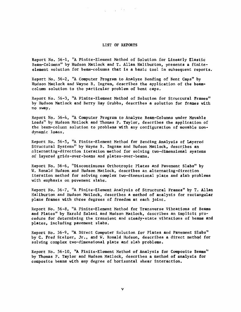
Report No. 56-1, "A Finite-Element Method of Solution for Linearly Elastic Beam-Columns" by Hudson Matlock and T. Allan Haliburton, presents a finiteelement solution for beam-columns that is a basic tool in subsequent reports.
Report No. 56-2, "A Computer Program to Analyze Bending of Bent Caps" by Hudson Matlock and Wayne B. Ingram, describes the application of the beamcolumn solution to the particular problem of bent caps.
Report No. 56-3, "A Finite-Element Method of Solution for Structural Frames" by Hudson Matlock and Berry Ray Grubbs, describes a solution for frames with no sway.
Report No. 56-4, "A Computer Program to Analyze Beam-Columns under Movable Loads" by Hudson Matlock and Thomas P. Taylor, describes the application of the beam-column solution to problems with any configuration of movable nondynamic 10aos.
Report No. 56-5, "A Finite-Element Method for Bending Analysis of Layered Structural Systems" by Wayne B. Ingram and Hudson Matlock, describes an alternating-direction iteration method for solving two-dimensional systems of layered grids-over-beams and p1ates-over-beams.
Report No. 56-6, "Discontinuous Orthotropic Plates and Pavement Slabs" by W. Ronald Hudson and Hudson Matlock, describes an alternating-direction iteration method for solving complex two-dimensional plate and slab problems with emphasis on pavement slabs.
Report No. 56-7, "A Finite-Element Analysis of Structural Frames" by T. Allan Haliburton and Hudson Matlock, describes a method of analysis for rectangular plane frames with three degrees of freedom at each joint.
Report No. 56-8, "A Finite-Element Method fo1;' Transverse Vibrations of Beams and Plates" by Harold Sa1ani and Hudson Matlock, describes an implicit procedure for determining the trans.ient and steady-state vibrations of beams and plates, including pavement slabs.
Report No. 56-9, "A Direct Computer Solution for Plates and Pavement Slabs" by C. Fred Stelzer, Jr., and W. Ronald Hudson, describes a direct meth~d for solving complex two-dimensional plate and slab problems.
Report No. 56-10, "A Finite-Element Method of Analysis for Composite Beams" by Thomas P. Taylor and Hudson Matlock, describes a method of analysis for composite beams with any degree of horizontal shear interaction.
v

vi
Report No. 56-11, '~Discrete-Element Solution of Plates and Pavement Slabs Using a Variable-Increment-Length Model" by Charles M. Pearre:, III, and W. Ronald Hudson, presents a method for solving freely discontinuous plates and pavement slabs subjected to a variety of loads. April 1969.
Report No. 56-12, '~Discrete-Element Method of Analysis for Combined Bending and Shear Deformations of a Beam ll by David F. Tankersley and William p. Dawkins, presents a method of analysis for the combined effects of bending and shear deformations. December 1969.
Report No. 56-13, "A Discrete-Element Method of MUltiple-Loading Analysis for Two-Way Bridge Floor Slabs" by John J. Panak and Hudson Matlock, includes a procedure for analysis of two-way bridge floor slabs continuous over many supports. January 1970.
Report No. 56-14, "A Direct Computer Solution for Plane Frames" by William P. Dawkins and John R. Ruser, Jr., presents a direct method of Holution for the computer analysis of plane frame structures. May 1969.
Report No. 56-15, ''Experimental Verification of Discrete-Elenent Solutions for Plates and Slabs" by Sohan L. Agarwal and W. Ronald Hudson, presents a comparison of discrete-element solutions with small-dimension test results for plates and slabs, including some cyclic data. April 1970.
Report No. 56-16, ''Experimental Evaluation of Subgrade Modulus and Its Application in Model Slab Studies"'by Qaiser S. Siddiqi and W. Ronald Hudson, describes a series of experiments tc;:> evaluate layered foundation coefficients of subgrade reaction for use in the discrete-element method. January 19:70.
Report No. 56-17, I~ynamic Analysis of Discrete-Element Plates on Nonlinear Foundations" by Allen E. Kelly and Hudson Matlock, presents a numerical method for the dynamic analysis of plates on nonlinear foundations. July 1970.
Report No. 56-18, "A Discrete-Element Analysis for Anisotropic Skew Plates and Grids" by Mahendrakumar R. Vora and Hudson Matlock, describes a tridirectional model and a computer program for the analysis of anisotropic skew plates or slabs with grid-beams. August 1970.
Report No. 56-19, I~n Algebraic Equation Solution Process Formulated in Anticipation of Banded Linear Equations" by Frank L. Endres and Hudson Matlock, describes a system of equation-solving routines that may be applied to a wide variety of problems by using them within appropriate prograuls. January 1971.
Report No. 56-20, ''Finite-Element Method of Analysis for Pla,ne Curved Girders" by William P. Dawkins, presents a method of analysis that ms,y be applied to plane-curved highway bridge girders and other structural menIDers composed of straight and curved sections. June 1971.
Report No. 56-21, ''Linearly Elastic Analysis of Plane FrameE, Subjected to Complex Loading Conditions" by Clifford O. Hays and Hudson Nat1ock, presents a design-oriented computer solution for plane frames structures and trusses that can analyze with a large number of loading conditions.. June 1971.

vii
Report No. 56-22, "Analysis of Bending Stiffness Variation at Cracks in Continuous Pavements, II by Adnan Abou-Ayyash and W. Ronald Hudson, describes an evaluation of the effect of transverse cracks on the longitudinal bending rigidity of continuously reinforced concrete pavements. April 1972.
Report No, 56-23, I~ Nonlinear Analysis of Statically Loaded Plane Frames Using a Discrete Element Model" by Clifford O. Hays and Hudson Matlock, describes a method of analYSis which considers support, material, and geometric nonlinearities for plane frames subjected to complex loads and restraints. May 1972.
Report No. 56-24, "A Discrete-Element Method for Transverse Vibrations of BeamColumns Resting on Linearly Elastic or Inelastic Supports" by Jack Hsiao-Chieh Chan and Hudson Matlock, presents a new approach to predict the hysteretic behavior of inelastic supports in dynamic problems. June 1972.
Report No. 56-25, I~ Discrete-Element Method of AnalYSis for Orthogonal Slab and Grid Bridge Floor Systems" by John J. Panak and Hudson Matlock, presents a computer program particularly suited to highway bridge structures composed of slabs with supporting beam-diaphragm systems. May 1972.
Report No. 56-26, I~pplication of Slab Analysis Methods to Rigid Pavement Problems" by Harvey J. Treybig, W. Ronald Hudson, and Adnan Abou-Ayyash, illustrates how the program of Report No. 56-25 can be specifically applied to a typical continuously reinforced pavement with shoulders. May 1972.
Report No. 56-27, l~inal Summary of Discrete-Element Methods of Analysis for Pavement Slabs" by W. Ronald Hudson, Harvey J. Treybig, and Adnan Abou-Ayyash, presents a summary of the project developments which can be used for pavement slabs. August 1972.
Report No. 56-28, "Finite-Element Analysis of Bridge Decks" bv Mohammed R. Abdelraouf and Hudson Matlock, presents a finite-element analysiS which is compared with a discrete-element analysiS of a typical bridge superstructure. August 1972.

!!!!!!!!!!!!!!!!!!!"#$%!&'()!*)&+',)%!'-!$-.)-.$/-'++0!1+'-2!&'()!$-!.#)!/*$($-'+3!
44!5"6!7$1*'*0!8$($.$9'.$/-!")':!

ABSTRACT
A finite element method is presented for the analysis of bridge decks
treated as shell-type structures. The method can be used successfully for the
analysis of a wide variety of highway bridges such as slab-type bridges, beam
slab bridges, box girder bridges, and curved bridges.
The deck is discretized as an assemblage of flat triangular elements.
Four different elements are available for use in the analysis. Two of these
are in the forms of a new, refined triangular element and a new, refined non
planar quadrilateral element, and the other two elements are a triangular ele
ment and a quadrilateral element with less refinement of stiffness evaluation.
The refined elements are suitable for use in coarse meshes to analyze decks
with simple geometry while the other two elements may be used in fine meshes
for the analysis of decks with complex geometry.
A six-degree-of-freedom nodal point displacement system is used in the
analysis. Such a system is enough for complete representation of the shell
problem and at the same time 'permits mesh refinement for representation of
structures with complex geometries.
Orthotropic material properties as well as elastic supports are considered.
The method offers considerable flexibility in expressing practical cases of
loads and support conditions together with simplicity of the input data.
A continuous five girder bridge and a continuous box girder bridge were
analyzed, and the results are compared with four existing solutions.
KEY WORDS: finite element, bridge decks, shell-type structures, geometric
idealization, element, nodal point, mesh, orthotropic material, curved
bridges, elastic supports.
ix

!!!!!!!!!!!!!!!!!!!"#$%!&'()!*)&+',)%!'-!$-.)-.$/-'++0!1+'-2!&'()!$-!.#)!/*$($-'+3!
44!5"6!7$1*'*0!8$($.$9'.$/-!")':!

SUMMARY
A finite element method is presented for the analysis of bridge decks.
This is a general method which can be used successfully for the analysis of a
wide variety of highway bridges as well as other highway constructions such as
culverts and retaining walls.
Orthotropic material properties as well as elastic supports are considered.
The method offers considerable flexibility in expressing practical cases of
loads and support conditions together with simplicity of the input data. The
method has been tested and gave excellent results in the analysis of typical
straight and curved bridges.
xi

!!!!!!!!!!!!!!!!!!!"#$%!&'()!*)&+',)%!'-!$-.)-.$/-'++0!1+'-2!&'()!$-!.#)!/*$($-'+3!
44!5"6!7$1*'*0!8$($.$9'.$/-!")':!

IMPLEMENTATION STATEMENT
An extremely useful method for the analysis of bridge decks is reported
herein. The method features considerable generality and simplicity in the in
put, thus enabling highway engineers to perform accurate analyses with mini
mum approximations for modern bridges. Complicated geometries can be easily
represented as well as elastic supports and orthotropic material properties.
The program offers considerable economy in analyzing bridges for various
load cases if all the load cases are solved in the same computer run. It
includes various output options and is constructed in such a way to facilitate
future developments.
xiii

!!!!!!!!!!!!!!!!!!!"#$%!&'()!*)&+',)%!'-!$-.)-.$/-'++0!1+'-2!&'()!$-!.#)!/*$($-'+3!
44!5"6!7$1*'*0!8$($.$9'.$/-!")':!

TABLE OF CONTENTS
PREFACE
LIST OF REPORTS
ABSTRACT
SUMMARY .
IMPLEMENTATION STATEMENT
NOMENCLATURE
CHAPTER 1. INTRODUCTION
Finite Element Analysis of Shell-Type Structures . . . . The Finite Element Method . . . . . . . . . . . . Approximations in Finite Element Analysis of Shell-Type
Structures . . . . . . . Finite Element Approaches The Present Method of Analysis
CHAPTER 2. THE PRESENT METHOD OF ANALYSIS
Geometric Idealization . . . . . . . . Displacement Field Idealization Construction of the Element Stiffnesses Coordinate Systems and Transformations • Representation of Material Properties and Loads Construction of the Total Stiffness Matrix .. The Structure Stiffness Matrix and Solution of Element Forces . . . . . . .. . ..... Solution of Problems, Remarks, and Limitations
CHAPTER 3. EXAMPLE PROBLEMS
Example 1. Example 2. Example 3.
Cantilever Beam . . . . Beam-Slab Type Bridge Box Girder Bridge
Equations
iii
v
ix
xi
xiii
xvii
2 2
4 6 7
11 13 15 18 25 27 35 38 39
43 47 61
CHAPTER 4. SUMMARY AND CONCLUSIONS . . • . . . . • . . . . . . . . • .. 79
xv'
REFERENCES 83
APPENDIX. SELECTED COMPUTER OUTPUT . . • . . . . . . . . • . . . . . . . 87
xvi

Symbol
X, Y, Z
X, Y, Z
0' l' 0'2 '
u
v
w
e , e x y
[R}
[r}
[TJ
[TJ
[K]
[Q}
[d}
[J]
[S}
[M}
'¥
[C]
[C ] p
C .. l.J
Typical Units
in
in
in
rad
lb
in
rad
Ib/in2
NOMENCLATURE
Definition
Global coordinates
Element coordinates
Generalized coordinates
In-plane displacement component
In-plane displacement component
Lateral displacement component
Angles of rotation
Force vec tor
Displacement vector
Direction cosines matrix
Transformation matrix
Stiffness matrix
Force vec tor
Displacement vector
Stress transformation matrix
In-plane stress vector at a point
Bending vector at a point
Angle of in-plane stress or bending transformation
Moduli matrix
The moduli matrix w.r.t. the principal axes
Element in C matrix p
xvii

Symbol
E , E , E x Y
\) xy' \)yx' \)
G 0
G
[KQ
]
[rQ}
[RQ
}
[K ] e
[R } e
[r } e
Typical Uni ts
lb/in2
Definition
Moduli of elasticity
Poisson's ratio
Orthotropic shear modulus
Isotropic shear modulus
Stiffness matrix of a quadrilateral element
Displacement vector of a ~uadrilateral element
Force vector of a quadrilateral element
Condensed quadrilateral element stiffness matrix
Condensed quadrilateral element load vector
Displacement vector correspondi.ng to the external nodes of the quadrilateral element
xviii

CHAPTER 1. INTRODUCTION
In recent years, an increasing importance has been given to the design
and construction of bridge decks. This is due primarily to (1) the increase
in magnitude of the moving loads, (2) the need for an economical use of
construction materials, and (3) the complicated geometries of modern bridges
and their longer spans. To meet these requirements, materials of higher
strength are being used, and accurate methods of analysis must be developed.
Several methods are available for the analysis of bridge decks. In each
method some simplifying assumptions usually exist in order to facilitate anal
ysis. The accuracy of the solution obtained by a given method depends on the
accuracy of representation of the structure and the extent of the approximations
involved in the method.
Early methods of analysis required a considerable amount of approximation
in representing the structure. A typical example of such approximation is the
division of a bridge deck composed of a slab and a system of girders into one
or more levels of secondary structures supported by main structures. Another
example is the discrete-element modeling of slab type and beam-slab type
bridge decks (Refs 1, 2, and 3). While such simple methods furnish a good and
fast solution for some types of simple bridge decks, it is difficult to apply
such methods to modern bridges with complicated geometries.
For such modern bridges, the recent trend is to treat the whole deck as
a shell-type structure. This procedure makes it feasible to represent most of
the details of the bridge, such as single and double curvature, variable girder
depth, girder-slab interaction, boundary details, and variations of material
properties. A finite element method for the analysis of shell-type structures
was recently presented by the authors (Ref 4). This method can be used
successfully for the analysis of a wide variety of bridge decks, and it is the
primary subject of the following discussion.
1

2
Finite Element Analysis of Shell-Type Structures
Shell-type structures are those Which have small thickness compared to
the other dimensions of the structure or those composed of a group of such
relatively thin parts. Within this category are a variety of important build
ing and industrial constructions such as thin curved shells, folded plate struc
tures, silos, bunkers, aqueducts, culverts, liquid tanks, docks, and several
kinds of bridges. For these structures, the shell behavior assumption can be
considered as a good approximation for the actual behavior of the structure.
In other words, the structure or its component parts can be treated as two
dimensional surfaces rather than as three-dimensional solids. Consequently,
the case of plane stress can be assumed in which the stresses in the direction
normal to the middle surfaces of the shell are considered of negligible effect.
Also, Kirchhoff's assumption that straight lines normal to the middle surface
of the shell remain straight and normal to that surface during deformation
can be considered valid for these structures.
Many procedures for the analysis of shell structures are available.
Their capabilities range from limitations to particular kinds of structures,
such as the mathematical analysis of cylindrical shells and spherical domes,
to generality of handling any structure with any geometry, material properties,
or loading variations. Usually, the more general method of solution is
desirable; however, the special purpose solutions provide ease in application
and interpretation of the results.
Recently, the rapid development of the finite element method of structural
analysis and the fantastic progress in the speed and memory size of digital
computers have made the general purpose solutions a practical approach to the
analysis of shell-type structures.
The Finite Element Method
The finite element method is a general approach to structural analysis.
Its generality makes it the most suitable one for analysis of structures with
arbitrary properties or geometries. Practical application of this method for
the analysis of shell type structures or similar structural problems requires
the use of a digital computer of suitable size and speed. The finite element

method is a numerical procedure for the approximate solution of problems in
continuum mechanics in which the actual structure is represented as an assem
blage of finite elements interconnected at a finite number of nodal points.
3
In each element of the assemblage, the displacement patterns are assumed to
vary in such a way as to approximate the actual displacements. The stiffness
of each element corresponding to the assumed degrees of freedom at the element
nodes is evaluated using the assumed displacement function. The degree of
accuracy of the resulting element stiffness, which usually has the most signif
icant effect on the final solution, depends on the degree of reality in the
chosen displacement variation. The element stiffnesses are assembled in the
proper manner to form the structure stiffness matrix. After proper modifica
tions for the boundary conditions have been made, the rows of the structure
stiffness matrix provide the coefficients relating the nodal point displace
ments to the applied nodal point loads. Thus, for the given nodal point loads,
the displacements corresponding to the assumed degrees of freedom at the nodes
can be evaluated. The element strains and stresses can then be obtained using
the calculated nodal point displacements, the assumed displacement variations,
and the material elastic properties of the element. The theory and application
of the finite element method in structural and continuum mechanics is discussed
in detail in Ref 5, which also contains an extensive list of additional refer-
ences.
The earliest use of the finite element method for the computer analysis
of elastic continua was in problems of plane stress and plane strain (Refs 6
and 7). The method was then applied to the plate bending problem (Ref 8).
The success obtained with these two applications was a motivation for applying
the method to the analysis of th~n shell problems. The earliest programs for
the analysis of thin shells using the finite element method utilized flat
elements in which the membrane and bending stiffnesses were evaluated indepen
dently (Ref 9). Flat rectangles were used in analyzing cylindrical shells, and
flat triangles were proposed for approximating doubly curved surfaces (Ref 10).
Later, Johnson (Ref 11) used flat triangles in the analysis of thin shells.
After that, several achievements were obtained which materially improved and
added to the flexibility of the method. Refined elements were developed and
used in the analysis (Refs 12 and 13). Curved elements were developed as a

4
better way for representing curved surfaces (Refs 14, 15, and 16). Thick
shells were also analyzed using thick finite elements (Ref 17). Also, com
pound elements were built by assembling groups of the simple ,;lements. Refer
ence 18 contains a more detailed discussion of the developmen'::s of the method
and a comparison of the results that were obtained using some of the different
types of elements.
The two properties of the finite element method which make it a valuable
method of structural analysis are its generality and the arrangement of the
resulting equilibrium simultaneous equations. It can be easily seen that the
method is a systematic, uniform procedure for the analysis of structures re
gardless of the types or shapes of the finite elements used in the structural
idealization. The procedures for analysis of space trusses using bar type
elements or space frames us beam type elements or a shell structure using
flat or curved plate elements are essentially the same. The::mly place where
a difference may exist is in the evaluation of the stiffness 'properties of the
constituting finite elements. The resulting total stiffness .natrix generally
contains only a few non-zero terms; and, by a suitable arrangement of the
nodal point numbering of the structure, these non-zero terms can be located in
a narrow strip around the major diagonal of the stiffness matrix. The result
ing symmetric banded stiffness matrix saves considerably in the time required
for solution of the simultaneous equations by making possible the use of
special efficient methods for solving such kinds of simultaneous equations.
Approximations in Finite Element Analysis of Shell-Type Structures
Finite element analysis of shell-type structures involves some approxima
tions which can be divided accor~ing to their nature into two groups. The
first group comprises those approximations which exist in any thin shell or
thin plate analysis method while the second group includes those approximations
which exist specifically in the finite element method. The first group of
approximations arises from the assumption that the stresses normal to the
middle surfaces of the structure are of negligible effect. This justifies the
treatment of the structure or of its component parts as a two-dimensional
surface rather than as a three-dimensional solid. This simplifying assumption

5
is good only for very thin-walled structures. For structures of intermediate
or large thickness this approximation could be the main source of error. As
mentioned before, this is one of the approximations in the finite element
analysis of shell-type structures, but it is not a special feature of the
method. The second group of approximations can be considered as special fea
tures of the finite element method and can be divided according to source into
the two main approximations described below.
The Geometric Approximation. The first step in the analysis of a struc
ture using the finite element method is to idealize the structure as an
assemblage of finite elements. The finite elements should have a simple
geometry in order to make the evaluation of their stiffnesses feasible. Com
mon examples of such elements are flat or curved triangles, flat or curved
rectangles, flat quadrilaterals, and nonplanar quadrilaterals composed of
planar triangles. The use of such simple elements to idealize structures of
arbitrary geometry usually results in a difference between the actual structure
and the idealization. A common example is the representation of curved bound
aries by segments of straight lines. The effect of the geometric approximation
can be reduced by reducing the size of the elements. Furthermore, a wide
variety of shell-type structures, such as folded plate structures and most
kinds of bridges, can be easily idealized without any approximations.
The Displacement Field Approximation. In calculating a finite element
stiffness matrix, the variation of the displacements within the element must
be assumed. The degree of approximation in this assumption is usually the
most significant factor affecting the accuracy of the solution. Theoretically,
in order to represent a general variation of displacements exactly, a poly
nomial of infinite degree is required; but practically, only the first few
terms of such a polynomial are enough. The size of the element stiffness
matrix, the computational effort required for its evaluation, and the accuracy
of the results obtained all increase with an increase in the number of terms
considered from the general polynomial representation of the displacements. A
compromise must be reached here to achieve the required degree of accuracy
with an acceptable amount of computation.

6
A usual trend is to assign ~o the lateral displacement of a flat element
a displacement function of higher order than that assumed for the in-plane dis
placement function. This assumption may give rise to a kind of incompatibility
in solutions using such elements. This incompatibility exists at element
interfaces when they meet at a non-zero angle.
The effect of displacement approximation in most of the finite elements
used in structural analysis (including the elements used here) decreases as
the element size decreases. Also, in most cases, the incompc:tibility due to
the difference in the displacement functions within flat elerrtents is insignif
icant, and its effect can be reduced by reducing the element size.
Finite Element Approaches
The analysis of shell-type structures by the finite element method can
be approached in two different ways:
(1) by using coarse meshes composed of refined finite E:lements, and
(2) by using fine meshes composed of relatively less n:fined finite elements.
In the first approach the amount of input data is reduced, and consequently
the effect of data preparation and the probability of data error are relative
ly smaller. The main disadvantage of this approach is its limited flexibility
in idealizing complex geometries such as the details of compJ.ex, doubly
curved surfaces. In such cases the use of fine meshes of refined elements to
physically represent the complex geometry may result in an unacceptable in
crease in the solution time. The main advantage of the second approach is its
flexibility in representing complex geometries. This requires more data than
the first approach. In structur"es with simple geometries this approach may
have no advantage, and the solution time required for a certain degree of
accuracy may not favor its use.
Within either of these two approaches the number of nodal point degrees
of freedom considered in the analysis may vary from five to twelve or more.
Generally, the minimum number of nodal degrees of freedom fo:r shell analysis
purposes is six. Usually, these six degrees of freedom are chosen as three
translation components and three rotation components.

7
The five-degree-of-freedom nodal point system may give good representation
in many cases if it is used in such a way as to minimize the effect of the
omitted degree of freedom, as in the analysis presented in Ref 11. This
analysis considers the five degrees of freedom as three translation components
in the directions of the three global axes and two rotation components about
two axes in a plane tangential to the structure surface at the node considered.
This system is equivalent to specifying the bending rotation component about
the axis normal to the surface at each node to be zero. This constraint has
proved to have little effect in cases of intersecting surfaces, such as box
girder bridges; however, the tangent plane becomes undefined. In such cases,
improper choice of this plane may result in considerable error. The necessity
of defining the direction cosines of the two tangent axes as input data at
each point is inconvenient; and the method may not be applicable for cases in
which all three rotation components are of the same order of magnitude.
Reference 19 analyzes continuous box girder bridges using a six-degree
of-freedom nodal point system and a rectangular element which gives good
results with relatively fine meshes. The main disadvantage of this method is
its limitation to rectangular geometries.
Reference 13 uses a nine-degree-of-freedom nodal point system for the
analysis of thin shell structures. This analysis uses a refined triangular
element and has considerable flexibility and generality. The main disadvan
tage of this analysis results from the nine degrees of freedom and especially
from the fact that six of these nine degrees are associated with the triangle
membrane stiffness. In other words, more refinement was devoted to the
membrane stiffness (complete cubic variation) than was given to the bending
stiffness (constrained cubic variation), an arrangement which generally may
not be necessary in the analysis of plates and shells.
The Present Method of Analysis
The purpose of the present work was to develop a finite element method
for analysis of shell-type structures that would include most of the finite
element generalities and would keep the input as simple as possible for the
purpose of users' convenience. Both of the approaches described in the previous
8
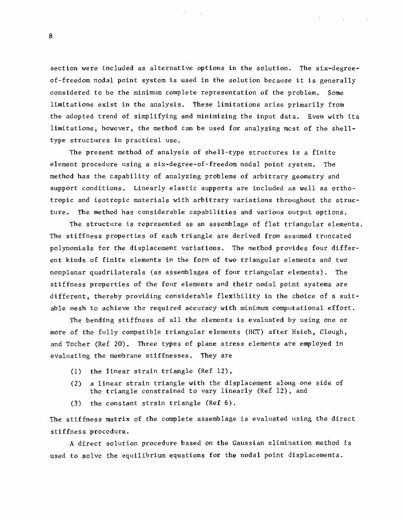
section were included as alternative options in the solution. The six-degree
of-freedom nodal point system is used in the solution because it is generally
considered to be the minimum complete representation of the problem. Some
limitations exist in the analysis. These limitations arise primarily from
the adopted trend of simplifying and minimizing the input data. Even with its
limitations, however, the method can be used for analyzing most of the she11-
type structures in practical use.
The present method of analysis of shell-type structures is a finite
element procedure using a six-degree-of-freedom nodal point s.ystem. The
method has the capability of analyzing problems of arbitrary geometry and
support conditions. Linearly elastic supports are included as well as ortho
tropic and isotropic materials with arbitrary variations throughout the struc
ture. The method has considerable capabilities and various output options.
The structure is represented as an assemblage of flat triangular elements.
The stiffness properties of each triangle are derived from assumed truncated
polynomials for the displacement variations. The method provides four differ
ent kinds of finite elements in the form of two triangular elements and two
nonp1anar quadrilaterals (as assemblages of four triangular elements). The
stiffness properties of the four elements and their nodal point systems are
different, thereby providing considerable flexibility in the choice of a suit
able mesh to achieve the required accuracy with minimum computational effort.
The bending stiffness of all the elements is evaluated by using one or
more of the fully compatible triangular elements (HCT) after Hsieh, Clough,
and Tocher (Ref 20). Three types of plane stress elements are employed in
evaluating the membrane stiffnesses. They are
(1) the linear strain triangle (Ref 12),
(2) a linear strain triangle with the displacement along one side of the triangle constrained to vary linearly (Ref 12), and
(3) the constant strain triangle (Ref 6).
The stiffness matrix of the complete assemblage is evaluated using the direct
stiffness procedure.
A direct solution procedure based on the Gaussian elimination method is
used to solve the equilibrium equations for the nodal point displacements.

The equations are solved using rectangular blocks to perform the required
operations. The number of the rows in a block is variable and thus provides
added generality and flexibility in the solution. All the load cases are
solved together, thus saving considerably in the solution time required for
problems with more than one load case.
9
The thickness and the material properties are assumed constant for each
finite element of the assemblage. The material is characterized as either
isotropic or orthotropic. Thus, structures with smooth variations in thick
ness are approximated with abrupt steps in thickness. A similar approximation
must be made for complicated variations of material properties. These limita
tions are not significant in most practical cases, and their effect can be
reduced by reducing the element size. Some other limitations concerning the
boundary conditions and the application of load are mentioned in Chapter 2.
The method was tested and gave good results when compared to the results
of existing methods of analysis. It can be efficiently applied for the anal
ysis of a wide variety of shell-type structures, such as shells with single
and double curvatures, folded plate structures, bridges, liquid containers,
bunkers, and similar structures.
In this report, the application of the method to the analysis of highway
bridges is illustrated by analyzing two typical bridges in Chapter 3. The
results of the analysis are compared with previous solutions for the same
bridges, and the methods are discussed briefly. For purposes of comparison,
the analysis here was done for two straight bridges with existing solutions.
No curved bridge analysis was included here; however, a curved prestressed
railway bridge was recently analyzed in cooperation with the Texas Highway
Department (Research Project 3-5-71-155, "Static and Buckling Analysis of
Highway Bridges by Finite Element Procedures") using this method. Some other
curved structures were analyzed, and the results are included in Ref 4, which
contains more details of the method and of the computer program.

!!!!!!!!!!!!!!!!!!!"#$%!&'()!*)&+',)%!'-!$-.)-.$/-'++0!1+'-2!&'()!$-!.#)!/*$($-'+3!
44!5"6!7$1*'*0!8$($.$9'.$/-!")':!

CHAPTER 2. THE PRESENT METHOD OF ANALYSIS
The present method of analysis of shell-type structures is a direct
stiffness solution using the finite element method with a six-degree-of-freedom
nodal point system. Two main idealizations, or approximations, are present in
the analysis, namely the geometric idealization and the displacement field
idealization.
Geometric Idealization
The actual surface of the structure is discretized to an assemblage of
planar triangles. Four different finite elements are available for use in
the analysis as follows:
(1) The quadrilateral element with eight external nodes, Fig l(a), may be a nonplanar or a planar assemblage of four planar triangles. The external nodes are the four corner nodes and the four mid-side nodes. The coordinates of the center of this element are computed as the average of the coordinates of its corner points. This center is the common node of the four composing triangles.
(2) The quadrilateral element with four external nodes, Fig l(b), of which the geometry is the same as for the previous element but without the mid-side nodes.
(3) The planar triangular element with six nodes, shown in Fig l(c), which has three mid-side nodes as well as the three corner nodes.
(4) The planar triangular element with three nodes which is shown in Fig l(d).
The geometric idealization of a typical shell surface using quadrilateral
and triangular elements is shown in Fig 1(e). Figure 1 also shows the two
main systems of coordinates used in the analysis. The coordinate systems are
described later in this chapter. The shape and the size of each element are
determined from the global coordinates of its corner nodes, which should lie
in the middle surface of the structure. In general, anyone of the four elements
Can be used for idealizing the structure. Combination of these elements may
be necessary in some Cases to fit the geometry of the structure. It will be
seen later that for the same computational effort, the quadrilateral element
11

x
i m j
(a) (b) (c) (d)
Quadrilateral elements. Triangular elements-
z Coordinate definitions:
x, Y, Z = global coordinates
x, Y, Z = element coordinates
"X
(e) Idealized shell surface.
Fig 1. Elements used, coordiriate systems, and typical idealized shell.

13
with mid-side nodes gives better results than the triangular element with mid
side nodes. Also, the simple quadrilateral element possesses similar superior
ity over the simple triangle. Although it is possible to use any combination
of the four element types, it is usually most practical to (1) combine the
quadrilateral and the triangular elements having mid-side nodes or (2) combine
the two elements without mid-side nodes. The relative stiffness superiority
of the quadrilaterals in either of the two combinations usually necessitates
their use in regions of steep strain variations while the triangles may be
used in regions of smaller strain variations.
Displacement Field Idealization
The basic element in the displacement field idealization is the planar
triangle. The membrane and bending displacements of this basic triangle are
discretized to vary according to certain displacement functions. Three types
of membrane displacement discretizations and membrane stiffnesses are available
while one basic bending displacement discretization is used in all cases.
Membrane Stiffnesses of the Basic Triangular Elements. The triangular
elements used in evaluating the membrane stiffnesses and their displacement
functions (expressed in generalized coordinates Ql' Q2' ... , etc.) are
shown in Fig 2. Two degrees of freedom in the form of two perpendicular in
plane displacement components, u and v, are assumed at each nodal point.
The variation of these displacements is assumed to be quadratic in the case of
the linear strain triangle (Fig 2(a) and linear in the case of the constant
strain triangle (Fig 2(c). For the constrained linear strain triangle, the
displacements are assumed to have quadratic variations which gradually change
to linear variations toward the 'constrained side (side 1-2 in Fig 2(b».
Bending Stiffnesses of the Basic Triangular Element. The fully compatible
triangular bending element is used in all cases as a basic element for evalu
ating the bending stiffness. This element has a total of nine degrees of
freedom in the form of the lateral translation and two perpendicular rotation
components at each corner of the triangle. In order to achieve full compati
bility, the element is divided into three sub-elements, and three displacement

14
vl ult ----1
Displacement fUnctions:
u (x ,y) = 2 2 {l,x,y,x ,xy,y } {IJ t v2
{TJ ----2 u2 X
v(x,y) 2 2 == (l,x,y,x ,xy,y }
(a) Linear strain triangle (LST).
Displacement functions are similar to LST with:
=
==
(b) Constrained linear strain triangle.
Y Displacement functions:
u (x ,y) ::: {l,x,y}
v(x,y) (l.x,y} -. 2 u2
(c) Constant strain triangle.
Fig 2. Triangular elements and displacement functions for membrane stiffness.
{::}
I::}

15
functions are assumed for the three sub-elements, as shown in Fig 3 where the
displacement functions are expressed in generalized coordinates aI' a2
,
... , etc. This subdivision results in twenty-seven displacement modes; but
only nine of them, corresponding to the corner degrees of freedom, are inde
pendent displacement modes. The internal compatibility requirements provide
the eighteen conditions needed for reducing the total twenty-seven displace
ment modes to the independent nine modes. This discretization expresses a
cubic variation of the lateral deflection, w, within the element and a linear
variation of the three curvature components over each sub-element except at
the edge of the sub-element where the twisting curvature is constrained to be
uniform.
The derivation of the membrane stiffness and the bending stiffness of the
basic triangles is given in Ref 4, Appendix 1.
Construction of the Element Stiffnesses
The element stiffness of each of the four element types is constructed by
using one or more of the basic membrane triangles together with one or more of
the basic bending triangles.
The Triangular Element with Three Nodes. The membrane stiffness of this
element is that of a constant strain triangle, and its bending stiffness is
that of the basic bending triangle. Thus, this element has a total of fifteen
degrees of freedom, five at each node, as shown in Fig 4(a).
The Triangular Element with Six Nodes. The membrane stiffness of this
element is that of the linear strain triangle, and its bending stiffness is
the sum of four triangular bending elements, each triangle representing one
of the sub-triangles shown in Fig 4(b). It should be noted that these four
sub-triangles are coincident; therefore, for the constant thickness case
treated here, the bending stiffness of only one of these sub-triangles, for
example, sub-triangle 1, is to be evaluated. The bending stiffnesses of sub
triangles 2 and 3 are identical to that of sub-triangle 1, and that of sub
triangle 4 can be obtained by transforming the bending stiffness matrix of
sub-triangle 1 in its plane through an angle of 180°. This coincidence of

16
1 exl~ ----.
w1
X
(3) w
w (1)
w (2)
Displacement functions:
{ 223 2 3 1,X3'Y3,x3,X3Y3'Y3,x3,X3Y3'Y3} n~ }
22323 FO} = [1,xl'Yl,xl,xlYl'Yl,xl,X1Yl'Yl} 0'18
22323 {?9} = [1,x2'Y2,x2,x2Y2'Y2,X2,X2Y2'Y2} 0'27
Fig 3. Triangular element and displacement functions for bending stiffness.

(a) Triangular element with 3 nodes and 15 DOF.
(b)
y
Triangular element with 6 nodes and 30 DOF.
3
(c)
1
4
9y3 t :3 t u3 9x3 3 ~_
3
5
(d)
2
Fig 4. Triangular elements and quadrilateral elements composed of four triangular elements each.
17

18
the four sub-triangles makes it possible to obtain refined bending stiffness
with only slight extra computational effort beyond evaluating the bending
stiffness of one triangle. This is true only in the case of constant thickness.
In cases of variable thicknesses it may be necessary to compute four triangular
element stiffnesses in order to achieve similar bending stiffness refinement.
This element has 30 degrees of freedom.
The Quadrilateral Element wi th Four External Nodes. This element, Fig 4(c),
is composed of four triangles. The membrane stiffness of each composing
triangle is that of the constrained linear strain triangle, and its bending
stiffness is that of one triangular bending element. Therefore, the corner
nodes of each composing triangle have five degrees of freedom each while the
mid-side nodes each have only two in-plane translation degrees of freedom.
The Quadrilateral Element with Eight External Nodes. This element, Fig 4(d),
is composed of four triangular elements with six nodes similar to the element
described earlier and shown in Fig 4(b).
Coordinate Systems and Transformations
The Global Coordinate System. This is a right-hand Cartesian system,
Fig l(e), which is independent of the mesh. The choice of the global coordi
nate axes is generally arbitrary, although in some cases the geometry of the
structure, the loading, or the boundary conditions indicate the suitable choice.
The following information is described in this coordinate sy:~tem:
(1) the input nodal point coordinates,
(2) the input nodal point loads,
(3 ) the input boundary con.di tions, and
(4) the computed nodal point displacements.
The Element Coordinate System. This is also a right-hand Cartesian system
which is associated with the element as shown in Fig 1. The element coordinate
axes are set for each element according to the order of input of the element
nodes in the element numbering.
For triangular elements, the order of numbering should follow the
alphabetical sequences shown in Figs l(c) and l(d). The first corner node is

19
considered as the origin of the element coordinates, and the X axis coincides
with the first triangle side (side i-j). The Y axis is perpendicular to
the X axis in the plane of the triangle; and the Z axis is normal to the
X-Y plane following the right-hand rule.
The numbering sequence for quadrilateral elements is shown in Figs lea)
and l(b). The coordinates of the center of the element are computed as the
average of the coordinates of the four corner nodes; and this center is the
origin of the element coordinates. The X-Y plane is taken as the average
element plane. This average plane is defined by the two straight lines join
ing the mid-side points of each pair of facing sides and intersecting at the
element center. The X axis is taken as the line through the mid-side nodes
of the fourth and the second sides (sides l-i and j-k, respectively); the
Y axis is constructed perpendicular to the X axis in the average plane; and
the Z axis is normal to the X-Y plane following the right-hand rule. In
the case of a planar quadrilateral, the average plane will be the same as the
plane of the element.
The following information is expressed in the element coordinates:
(1) the input orientation of the orthotropic material axes
(2) the computed element forces.
Local Coordinates for Quadrilateral Elements. Local coordinate axes are
established for each of the four composing triangles of the quadrilateral
element. These local coordinates are similar to the element coordinates of
the triangular elements, Figs l(c) and led). The establishment of these local
coordinates is done internally in the program for the purpose of computing
and transforming the triangle stiffness matrix and the equivalent nodal point
loads for the distributed loads; None of the input or output information is
expressed in these coordinates.
Triangular Coordinates. This local coordinate system is described in
Ref 4, Appendix 1. It is used to simplify the derivation of the stiffness
matrices of the triangular elements.
Coordinate Transformations. In the solution, several coordinate trans
formations are carried out to express in a cornmon coordinate system all the

20
variables appearing in a single computation process. All the transformations
of this kind are carried out between two Cartesian coordinate systems. Another
transformation between the local Cartesian coordinate system and the local
triangular coordinate system is described in Ref 4, Appendix 1. The first
kind of transformation is summarized below. Detailed derivations may be
obtained from textbooks on the subject.
Let th~ two Cartesian systems of coordinates be denoted as the X-Y-Z
system and the X'-Y'-Z' system. If the matrix T represents the direction
cosines of system X'_yl_Z' with respect to system X-Y-Z , then the trans
formation relations described below can be easily proved.
Linear Transformations.
R x' R r , r x x x
R y' = [1J R and r y' = [1J r y y
R z' R r z' r z z
or
R' == T· R and r' = T· r (2.1)
where Rand r are force and displacement vectors, respectively, at a
certain point in the X-Y-Z system, and R' ,r' are the corresponding vectors
in the X'-Y'-Z' system. It should be noted here that force means a general
force which may be moment and that displacement may actually be rotation.
The inverse relations are
R == -T T
where the matrix -T T
R' and r = r'
is the transpose (or the inverse) of the matrix T.
(2.2)

21
If all the force and displacement components at the nodal points of a
finite element are grouped in the same manner as the vectors above, then the
linear transformation relations for the element forces and displacements would
have the forms
Q' T . Q and d' = T· d (2.3)
Q' , Q ,d' and d are, respectively, the vectors containing n subvectors
R' R r' and r at all the nodal points of the element. T is the trans
formation matrix composed of n repetitions of the matrix T on the diagonal
strip as follows:
T
Similarly, the inverse relations are
Q = TT . Q' and
T n
d = TT. d'
(2.4)
(2.5)

22
Stiffness Transformation. If the element stiffness matrix is arranged to
correspond to similar degrees of freedom as the vectors d and d' in the
previous case, then the stiffness transformation relations would be
K' T = T· K . T and K TT . K' • T (2.6 )
where K' and K are the element stiffness matrices in the X'-Y'-Z' system
and the X-Y-Z system, respectively, and T and TT are the transformation
matrix defined by Eq 2.4 and its transpose, respectively.
Planar Transformation of Stresses. To transform plane stress components
at a point expressed in X-Y coordinates to the corresponding components in
X'-Y' coordinates, the transformation relation is
2 '¥ sin
2 '¥ 2 sin '¥ ~r Ox, cos cos 0 x
2 '¥
2 2 '¥ '¥ 0 y' = sin cos '¥ - sin COE: 0 y
2 -, sin '¥ '¥ sin '¥ cos '¥ '¥ sin
L.
'¥ ,. x'y' - cos cos - T xy
or
[S'} = [J'] [S} (2.7)
where 0 0, and ,. x y xy
are the membrane stress components defined in
Fig 5(a), which shows their positive directions; o , , 0 , " and T, , x y' x Y
are
the corresponding transformed stresses; and is the angle between the X
axis and the X' axis measured from the former to the latter and positive in a
counterclockwise direction.

23
A similar relation can be written for the transformation of the plate
bending moment components defined as shown in Fig 5(b).
M x' M x
M y' = [Jl M y
M x'y' M xy
or
[M'} = [J] [M} (2.8)
The inverse relations to those of (2.7) and (2.8) are
'\ [JJ -1 [ J [8.r = 8' and [M} (2.9)
where the matrix CJ]-l is the inverse of the matrix eJl and can be easily
obtained by substituting a negative value for ~ in the previous expression
for [J] Thus,
2 ~ sin 2
~ -2 sin 'V cos ~ cos
[Jr1 sin
2 ~
2 ~ 2 sin '!' cos ~ cos
sin ~ cos ~ sin ~ ~ 2 'V _ 2
~ (2.10) - cos cos sin
Planar Transformation of Moduli. For orthotropic material in the case of
plane stress, if the principal ~ateria1 axes are taken as axes X and Y
then any case of plane stress can be related to the corresponding strains in
the X-Y system as
C1 X
a y
.,xy
E: X
where [Cpl is the moduli matrix in the principal axes X and Y .
(2.11)

24
(a) Membrane stress components.
y
.. x
(b) Plate bending moment components.
Fig 5. Defj.lOition of membrane stresses and plate bending moments.
25
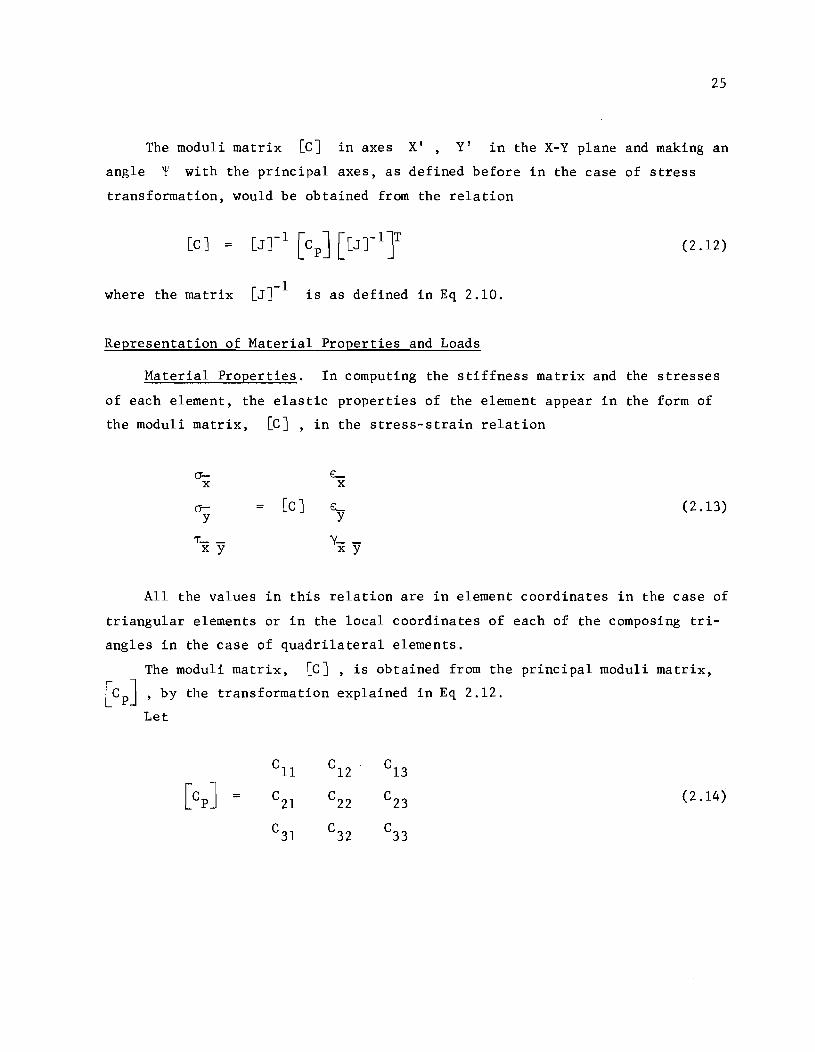
The moduli matrix [c] in axes X' , Y' in the X-Y plane and making an
angle ~ with the principal axes, as defined before in the case of stress
transformation, would be obtained from the relation
(2.12)
where the matrix [J]-l is as defined in Eq 2.10.
Representation of Material Properties and Loads
Material Properties. In computing the stiffness matrix and the stresses
of each element, the elastic properties of the element appear in the form of
the moduli matrix, [C], in the stress-strain relation
cr- E:-x x
a- = [C] L (2.13) y y
'T" __ y- -x y x y
All the values in this relation are in element coordinates in the case of
triangular elements or in the local coordinates of each of the composing tri
angles in the case of quadrilateral elements.
The moduli matrix, [C], is obtained from the principal moduli matrix,
[CpJ ' by the transformation explained in Eq 2.12.
Let
(2.14)

26
It can then be proved (Ref 21) that for orthotropic materials,
where
E Cll
x C22 = 1 - \! xy\!yx 1 - \! xy \!yx
\! E \! E C
12 = C2l = J::x x = xy y. 1 - \! \! 1 - \! \! xy yx xy yx
C33 = GO and C13 = C23 = C31 = C32 :;: 0 ,
E is the modulus of elasticity in the principal direction X x
E Y
\!xy
is the modulus of elasticity in the principal dIrection Y
is Poisson's ratio which results in strain in the Y direction when stress is applied in the X direction;
is Poisson's ratio which results in strain in the X direction when stress is applied in the Y direction; and
is the orthotropic shear modulus.
This orthotropic shear modulus is either measured as described in Ref 22 or is
assumed approximately as
= E E
x y. E (1 + \! ) + E (l + \! ) Y xy x yx
For isotropic materials,
E = =
1 - }
= G
=
=
2 1 - \!
= =
where E and \! are the modulus of elasticity and Poisson'8 ratio.
(2.15)
= o

The input values required to represent these two material cases are
described in detail in the guide for data input of Ref 4.
Applied Loads. The solution accepts two load types.
Concentrated loads at the mesh nodes are concentrated forces or moments
in the global coordinates at the mesh nodal points.
Distributed loads (element loads) are distributed on the surface of the
structure. Two types of distributed loads are accepted by the program.
(1) The element weight which is considered of constant intensity over each element and acting in the negative direction of the global Z coordinate. Therefore, whenever a problem includes this kind of load, the global Z coordinate should take the gravity direction. This may appear as a limitation; however, it is always possible to represent the weight by equivalent nodal point loads.
27
(2) Element pressure of linear variation of intensity over each triangle of the idealization and normal to it.
The equivalent nodal point loads for the element loads are computed as
described in Ref 4. Any number of load cases can be solved for the same struc
ture. In each load case the concentrated loads can be varied while the element
loads are either retai~ed or omitted as specified by the user. The description
of loads input is given in Ref 4, Appendix 3.
Construction of the Total Stiffness Matrix
The stiffness matrix of the assemblage is constructed from the stiffnesses
of the composing elements after these element stiffnesses are transformed into
a form suitable for assembling into the final six-degree-of-freedom system.
Triangular Elements. The membrane and bending stiffness matrices of the
composing triangles are assembled to correspond to five degrees of freedom at
each nodal point. The order of these degrees of freedom at node i is
U. 1.
v. 1.
&.-. , &.-. Xl. yl.
(2.16)
The stiffness terms corresponding to these five degrees of freedom are in
the element coordinates. When transformed to the global system of coordinates,

28
these five tenns at each node yield six stiffness components::orresponding to
the following global degrees of freedom:
o . , 1). , Xl Yl
e . , e. , Xl yl
e . 21
(2.17)
Therefore, for the systematic use of the form 2.6 in transforming the
element stiffness matrix, the stiffness terms in element coordinates must be
assembled into a six degree nodal point stiffness matrix in which the values
corresponding to the sixth term, at each node are equal to zeros. The trans
formation should then be performed, and the resulting stiffness terms would
correspond to the six global degrees of freedom of 2.17. The element stiffness
matrix transformed in this manner is then assembled in the structure stiffness
matrix according to the element location in the mesh as defir1.ed by its nodal
point numbers.
Quadrilateral Elements. The following steps are carried out in computing
and assembling the stiffness matrix of quadrilateral elementE:
(1) The stiffness matrix of each of the four composing triangles is first constructed in local coordinates, transformed to the global coordinate system, then assembled in the proper locations of the quadrilateral stiffness matrix. Similar operations are performed to evaluate the equivalent nodal force loads for the distributed loads on each triangle.
(2) The stiffness terms and the loads corresponding to the degrees of freedom of the internal points are condensed by an inverse Gaussian elimination procedure described below. The resulting condensed stiffness and loads correspond to the degrees of freedom of the external nodes and are the element's contributions to the equilibrium equations of the assemblage.
(3) The condensed stiffness and loads are assembled in the structure stiffness matrix and loads according to the external nodal point numbering.
Condensation of the Quadrilateral Stiffness Matrix. Th,a connectivity of
the internal nodes of each quadrilateral element is local to that element.
Therefore, according to the law of superposition, the effect of these internal
nodes may be included in the stiffness and loads of the external nodes. By
this process, known as condensation, the equilibrium equations of the internal

29
nodes are excluded from the total system of simultaneous equations of the
assemblage. The condensation process is illustrated by the following partition
ing of the matrix form of the equilibrium relation of the quadrilateral element:
K e
K. 1
K o
r e
r. 1
=
R e
R. 1
(2.18)
where KQ
, rQ
, and RQ are the stiffness matrix, the displacement vector,
and the load vector, respectively, of the quadrilateral element and correspond
to all its degrees of freedom; K r , and R are similar matrices e e e
corresponding to the external degrees of freedom only; and K is that 0
of the stiffness matrix which relates the external degrees of freedom to
internal degrees of freedom in the equilibrium equations of the external
degrees of freedom.
Therefore,
part
the
If all the coefficients of the matrix [KoJ are zeros, the relation 2.19
reduces to
(2.20)

30
From Eq 2.20, it is clear that the matrix [KeJ represents the condensed
stiffness matrix and that the load vector {RJ represents the condensed
load vector.
The process of converting all the coefficients of the matrix [KoJ to
zeros is carried out by the inverse Gaussian elimination method. As this
elimination is performed, the load vector is simultaneously reduced so
the condensed stiffness matrix, [KeJ, and the condensed load vector,
are obtained upon completion of the elimination operation. The matrix
that
R , e
[KiJ is thus transformed to the trapezoidal form indicated with all the
coefficients above the major diagonal equal to zero. After the external dis-
placements are calculated from the solution of the equilibri~m equations of
the assemblage, the matrix rKiJ is used to calculate the internal displace-
ments, {ri} , by a direct forward substitution in the relation
(2.21)
in which {Ri} should be in its converted form after condem.ation.
Inclusion of the Elastic Spring Supports. The elastic spring support
stiffnesses are expressed as the force (or moment) required to produce a unit
displacement in a particular global direc tion at a particular nodal point and
can be included directly in the structure stiffness matrix. This is done by
adding the spring stiffness to the diagonal term of the stiffness matrix which
corresponds to the appropriate degree of freedom at the nodal point where the
spring is.
Modifying the Stiffness Matrix for the Boundary Conditi'~. The struc
ture stiffness matrix and the load vector must be modified t.:) represent the
desired boundary conditions in the equilibrium relation
K • r = R (2.22)
where K r ,and R are the stiffness matrix, the displacement vector, and
the load vector, respectively, of the total structure.
31
The boundary conditions are either in the form of elastic spring supports
or in the form of specified displacement values in the global directions. The
method for including elastic spring supports in the structure stiffness matrix
has been described in the preceding section. To specify the value of a dis
placement (or rotation) component, the stiffness matrix diagonal which corre
sponds to the degree of freedom concerned is set equal to unity; all the other
stiffness terms in the row are set equal to zero; and the corresponding load
value is set equal to the specified displacement value. The displacement
value is thus specified, but the symmetry of the stiffness matrix has been
destroyed. To maintain symmetry, it is necessary to set equal to zero the
stiffness terms above and below the diagonal in the column corresponding to
the certain degree of freedom. In order to do this without changing the equi
librium relation, each term on this column must be multiplied by the specified
displacement value and the result subtracted from the corresponding load value
before the stiffness term is set equal to zero.
Omitting the Dependent Equations. It is important to notice that this
method is an analysis of a six-degree-of-freedom system using five-degree-of
freedom finite elements. At nodes where the elements intersect at a non-zero
angle, there are six degrees of freedom, and no precautions are required. At
nodes where the adjacent elements lie in the same plane or at mid-side nodes
on the edges, there will be an extra dependent equation (expressing rotation
equilibrium) corresponding to each of these nodes. In such cases it is impor
tant to omit or neutralize this extra equation in order to have a true solution.
Failure to do so would stop the solution of the equations; oi if a solution is
obtained, it will be a false solution. The omitted equation should satisfy
the following two conditions:
(1) It should not correspond to the rotation about any axis parallel to the plane at the nodal point.
(2) The omission should be overridden by any suitable boundary condition at the point that satisfies the independency condition at the nodal point.
If no such boundary condition exists, the best choice for reducing numerical
errors is to omit or neutralize the equation corresponding to the rotation
about the global axis which is most nearly normal to the plane at the node.

32
The process of omitting the dependent equations for a single node is
illustrated below. It can be seen that this process is valid for any linearly
elastic system.
Consider the bending stiffness matrix, [K] , at the node corresponding
to the rotation components about two arbitrary local axes, X and Y , which
is expressed as follows:
K = L_
Y x
L_ y y
(2.23)
Rewriting the above expression in terms of three rotation degrees of freedom
and setting the terms which correspond to the rotation about the local normal
axis, Z, equal to zero, we have
L_ L_ 0 x x Y x
K 0 K' = L_ ~- 0 ~ (2.24)
x y y y 0 0
0 0 0
The transformation matrix, T, expressing the relation between any
displacement vector, [r}, in the local coordinate system ( X - Y z ) and
the corresponding vector, [r}, in the global coordinate syEltem ( X - Y - Z )
(Eq 2.1) can be written as follows:
1 m n x x x
1 = C
1 8
1 T = m n
y y y 82
C2
1 m n z z z

33
The stiffness matrix [K] in the global axes is then obtained as
CT 1
ST 2
K 0 Cl Sl
K ST T
0 0 S2 C2 1 C2
T-CT K Sl k k C
l K Cl 1 xy (xy)z
= - (2.25) T- ST K Sl k k Sl K Cl 1 z(xy) z
Similarly, the corresponding moments, [M}, and the rotations, [a}, in
local coordinates can be written as
M-x M-_
M M- - x Y Y
0 0
and
8-x 8..-_
e a.... -x y
y
0 0
The moments, [M}, in global coordinates are
[M} = TT. M =
T C
l M-. -
x Y
ST M--1 x Y
M-x Y
o
M x Y
T Sl M-. -x Y
(2.26)

34
Consider the following relation:
In this relation, [ K J is as defined x y
in Eq 2.26. We can therefore solve for
Substituting for
in Eq 2.25 and {M }
e* . { } x :'I
y} in Eq 2.27, we ha~e
Premultiplying both sides by [CTIJ-I we get
Therefore,
Writing the rotations [e} in global coordinates, as
e x
e* e = e -
y
0 0
and then transforming these rotations to local axes, we get
(2.27)
is as defined
(2.28)
(2.29)
By this procedure we get the global rotations, {e*} , that are related
to the local rotations, {ex y} , by Eq 2.L8. When transformed to local
35
coordinates as described above, these global rotations give the correct local
rotations, {B- _~ , which are required to compute the bending moments at the x y) _ node. The value of the rotation about the Z axis as obtained in Eq 2.29 is not
correct, but it does not affect the computation of the bending moment. The
correct value of this component could be computed from the in-plane translations
at the node and at adjacent nodes. It is important to notice the following
energy equivalence:
JM- _}T {B- _~ l x Y X y)
It should be clear that the global rotations, {e*} , obtained are not the
total global rotation components at such a node. The correct three global
components of rotation could be computed as follows:
(1) Transform the rotations {e*} as in Eq 2.28 to compute the correct
local rotation components, {Bx y} . (2) Compute the local rotation component about the axis normal to the
surface Z from the in-plane translation components at the node and at the adjacent nodes.
(3) Transform the three local rotation components which are obtained to the global system in the usual manner.
The procedure outlined above results in the omission of the equation
corresponding to the rotation about the global Z axis. As mentioned before,
the program omits the equation corresponding to the global axis which is most
nearly normal to the plane at the node. In the output of the nodal point dis
placements, the symbol * * * replaces the rotation about the axis for which
the equation was omitted.
The Structure Stiffness Matrix and Solution of Equations
The structure stiffness matrix, as constructed in the preceding section,
is generally (1) symmetric, (2) positive definite, and (3) banded. These
three properties are very helpful when considered in the solution of the

36
simultaneous equations of equilibrium of Eq 2.22. Special, efficient equation
solvers exist for solving such equations. In these equation Holvers, the re
quired solution time is approximately proportional to the number of equations
and to the square of the band width; therefore, it is always desirable to have
the band width at a minimum. This can be achieved by a suitable choice of the
mesh numbering system.
Mesh Numbering and Band Width. The band width of the stl~ucture stiffness
matrix is the width of the zone that includes all the stiffne:;s terms on each
side of the diagonal. This is the shaded zone in Fig 6 (a). Because of the
symmetry of the stiffness matrix, only one half of this banded zone (including
the diagonal) is necessary for solution of the simultaneous equations of 2.22.
The upper half is used in the solution described below, and this half-width,
(including the diagonal) will be referred to as the band width. This band
width m is shown in Fig 6(a) and can be calculated for a certain mesh from
its element nodal point numbering as
m 6 X (D + 1) (2.30)
where D = the absolute maximum difference in the nodal point numbers of any
element in the assemblage. For example, the element shown in Fig 6(b) gives
D = 28 - 12 16
Therefore,
m 6 (16 + 1) 102
The maximum value of m for all the elements of the assemblage is the
band width of the structure stiffness matrix.
The mesh numbering should be chosen in such a way as to result in minimum
band width and therefore minimum solution time for the equilibrium equations.
Although no restrictions concerning the mesh layout exist, the recommendations
included later in this chapter are generally helpful in achieving an economical
solution.

(b)
T m
l
,i
-t i ~ n
(a) Structure stiffness matrix.
t-- m -----l I-- 1,
14 T 0 i
1 13
27
T D i
12 21 26 1
Example of element numbering. (c) Solution blocks.
Fig 6. Structure stiffness matrix, typical element numbering, and solution blocks.
37

38
Solution of the Simultaneous Equations of Eguilibrium. 1:1. direct solution
method based on the Gaussian elimination procedure is used to solve the simul
taneous equations of equilibrium. In the solution, the upper half of the banded
stiffness matrix is used. This half is divided into blocks each of which con
tains a certain number of rows of the stiffness matrix. The n.umber of rows,
i , in each block is determined by the core storage available for the equation
solution as well as by the band width, m, and by the number of load cases
analyzed. These blocks are handled in the rectangular form s::lOwn by Fig 6(c)
in which the two-dimensional array containing a particular block at a particular
stage in the solution process has the diagonal of the stiffness matrix as its
first column and the load vectors of all the load cases as its last columns.
All the blocks are of the same size except the last block which may have fewer
rows. More details of the equation solution are included in Ref 4. The solu
tion of the simultaneous equations yields the global nodal point displacements
of the structure for each load case.
Element Forces
After the nodal point displacements are computed, the stresses of each
element at some of its nodal points are calculated, if required, for all the
load cases. The element stress computation for each load case can be summa
rized as follows:
(1) The nodal point displacements at the nodes of triangular elements or of composing triangles of quadrilateral elements are transformed to element coordinates for triangular elements or to local coordinates for quadrilateral elements.
(2) The membrane and the bending stresses for each bastc triangle are computed according to the displacement func tion assigned to it (Ref 4, Appendix 1). If more than one basic triangle is used in constructing the stiffness matrix of the triangular element or of the composing triangle of a quadrilateral element, the stresses at the common nodes are averaged. This step gives the element stresseB in the case of triangular elements or the composing triangle streBses in the case of quadrilateral elements.
(3) For quadrilateral elements, the stresses of each cf;)mposing triangle are computed as in (2) and then transformed to elenent coordinates. The stresses of the four composing triangles are added and averaged at the common nodal points.

39
The stresses are output in the form of forces or moments per unit length
at the element nodes. A local numbering is used in the tabulated output of
these stresses to refer to the element nodes. This local numbering is shown
in Fig 7 for the four element types used in the analysis.
Solution of Problems, Remarks, and Limitations
The steps of coding a problem for analysis by this method are summarized
below. Any limitation of the solution which has not been mentioned before is
described at the step when it arises.
The mesh divisions used should be chosen to approximate the geometry of
the structure and the types of elements represented by these divisions should
be selected to give the most favorable representation of the expected deforma
tions as described earlier in this chapter. The nodal points as well as the
elements are numbered, and a global system of coordinates should be chosen.
Certain points must be observed in the mesh numbering and in the choice of the
global coordinates.
Mesh Numbering. The nodal point numbering should start with the number 1
and increase in a continuous manner. Element numbering should be done similar
ly. Only the external nodes of quadrilateral elements are to be numbered. No
limitations exist concerning mesh numbering; however, to reduce the solution
time required, two guidelines can be followed:
(1) The direction of element numbering should follow the direction of nodal point numbering. This considerably reduces the time required to assemble the structure stiffness matrix in the rectangular blocks described above.
(2) The band width should be kept at a minimum.
These two rules are observed in the example problems in Chapter 3. Some
flexibility in applying these rules may be desirable when the mesh generation
described in Ref 4, Appendix 3 ceases to be fully applicable as these rules
are applied. In such a case, the man-hours that can be saved by using mesh
generation may be more valuable than the computer time that can be saved by
following these two rules.

40
y y
3
3
.. .. 1 2
(a) Triangular elements.
x y
1 3
x
1 5 2
(b) Quadrilateral elements.
Fig 7. Local point numbering for element forees.

41
Choosing the Global Coordinate System. In addition to the limiting rela
tion between the global Z-direction and the structure weight as described
previously, one other important limitation may dictate the choice of the global
coordinate axes in some problems.
In order to simplify the input and minimize coding errors, all boundary
conditions are expressed in global coordinates. In most practical cases, this
limitation causes no difficulty in the coding or in the choice of the global
axes; however, in a few cases it may be impossible to represent the given
arbitrary boundary conditions. In some cases of complicated boundary condi
tions, it may be possible to represent such boundaries simply by setting the
global coordinate axes such that one or all of them lie in the directions of
the specified boundary. The following special cases can be indirectly repre
sented:
(1) Specifying any three independent translation (or rotation) components at a point can be achieved by specifying their global components. This situation often exists in practical cases as a fixed boundary with arbitrary inclination to the axes.
(2) Specifying any two translation components at a point in a plane parallel to one of three global planes is equivalent to specifying their two global components in that plane. Specifying two rotation components at a point achieves a similar result.
After the coordinate axes and the mesh numbering are chosen, the nodal
point coordinates can be calculated. Only the coordinates of the element
corner points must be necessarily input or generated. The rest of the problem
coding can be carried out as described in the guide for data input of Ref 4,
Appendix 3. There is one limitation which should be observed here.
No moment can be applied which is about an axis normal to the surface of
the structure at the point of application. Such a moment must be replaced by
equivalent in-plane concentrated loads at the adjacent points. Similarly,
specifying in-plane rotation can be done only by specifying in-plane displace
ment components.

!!!!!!!!!!!!!!!!!!!"#$%!&'()!*)&+',)%!'-!$-.)-.$/-'++0!1+'-2!&'()!$-!.#)!/*$($-'+3!
44!5"6!7$1*'*0!8$($.$9'.$/-!")':!

CHAPTER 3. EXAMPLE PROBLEMS
In this chapter, the solutions of some example problems are presented to
illustrate the application of the finite-element analysis of shell-type struc
tures (Ref 4) to the analysis of highway bridges. The input data of all these
problems is shown in the Appendix, which also includes complete output for one
problem.
The results of the present method of analysis are compared with the follow
ing previously available solutions which used different methods of analysis:
(1) the folded-plate method (Ref 19),
( 2) the finite-segment method (Ref 19),
(3) the finite element method (Ref 19),
(4) the discrete-element method of analysis of slabs and bridge decks (Refs 1, 2, and 3), and
(5) the theory of bending of shallow beams including shear deformation.
In these comparisons, the solutions are identified by the method names listed
above. If more than one solution is shown using the same method of analysis,
the solutions will be identified by the name of the method together with a
mesh number. It should be clear here that the word mesh stands for a certain
selection of element types and geometries for idealizing the analyzed structure.
Example 1. Cantilever Beam
The cantilever beam shown in Fig 8(a) is used to compare the results that
can be obtained by the present method to the theoretical results obtained from
beam theory. The problem was solved using four different meshes, each of which
utilizes one of the four elements available in the method. The four meshes
are shown in Figs 8(b), 8(c), 8(d), and 8(e), respectively. It should be
noted that the aspect ratios and the number of the constituting plate bending
elements (HCT's) for the two meshes of quadrilaterals are the same. This is
also the case for the two meshes of triangles.
The results are tabulated in Fig 8, together with the half band width of
the stiffness matrix, the number of simultaneous equations solved, and the
43

44
z
o
Y~I"--- 10.0
P3 = 72.75 P2 145.5
Q3 = 4.68 Q2 9.36
3000 \) 0.25
(a) Cantilever and loading
5 8 10 13 15 18 20 23 25 28
2 @ 7 @ 12 G) 17 ® 22 12) 27
1 4 6 9 11 14 16 19 21 :~4 26
(b) Mesh 1
3r 6 9 12 15 18 21 24 27 30 33
2 @ @ ® ® @ @ @ @ @ @
5 8 11 14 17 20 23 26 29 32
CD Q) G) (j) ® @ @ ~ @ ~
1 4 7 10 13 16 19 22 25 28
(c) Mesh 2
Fig 8. Example 1. Cantilever beam.

45
3 t Z
6 9 12 15 18 21 24 27 30 33
CD 2 8 32
Y .. 1 4 7 10 13 16 19 22 25 28 31
I Z
(d) Mesh 3
9 12 15 18 21 24 27 30 33 3
2 32
Y ~
1 4 7 10 31
(e) Mesh 4
Comparison of Results:
Tip Deflection Half Number Solution
5 0 cr Band of Time Mesh x z Y(max.) Width Equations (sec. )
(1) 98.1 99.6 8478 48 168 15
(2) 98.1 94.3 7638 30 198 23
(3) 97.9 99.2 8246 42 198 9
(4) 97.9 57.1 4840 30 198 14
Beam 100.0 100.0 8730 Theory
Fig 8. (Continued).

46
solution time for each mesh. The following points should be noted about the
results:
(1) The stiffness properties of the quadrilateral element with eight nodes and the triangular element with six nodes are superior to the stiffness of the other two types of elements. This is clear from comparing the tip deflections given by mesh 1 and mesh 3 to the tip deflections obtained in the beam theory solution.
(2) The membrane stiffness properties of the triangular element with three nodes and the quadrilateral element with four nodes are deficient in comparison to the membrane stiffness properties of the other two elements. This results from the assumption of linear displacements along the sides of the quadrilateral element or over the whole area of the triangular element. This deficiency in the membrane stiffness properties is also reflected in the membrane axial stresses obtained and is especially severe in the case of the triangular element.
(3) The solution time required for mesh 1 is less than that for mesh 2. Also, the solution time for mesh 3 is less than that for mesh 4 despite the fact that the latter has a smaller band width. This is due to the fact that other factors in addition to the equation solution may considerably affect the total solution time of a certain problem. It is clear here that the other significant factor is the number of elements. Evaluating the element stiffnesses and assembling them into the total stiffness matrix takes a considerable amount of the solution time.
All four elements are suitable for plate bending representation, with the
two elements which have mid-side nodes being more suitable for coarse meshes.
The elements with mid-side nodes offer the best tool for representation of in
plane deformation while the triangular element with three nodes provides the
least accurate representation. The quadrilateral element with four nodes usu
ally gives good representation of the in-plane deformation if it is used
(a) in a relatively fine mesh and (b) with aspect ratios not far from the range
of 1.0 to 2.0. For economical analysis of highway bridge decks, the use of the
elements with mid-side nodes may be limited to regions such as main girders
which undergo considerable in-plane strain variations while the other two
elements may be used in regions of lesser in-plane deformations such as slabs
or slab-type decks. If the quadrilateral element with four nodes is used to
idealize bending members such as main girders, there should be at least two
layers of elements on the beam depth.

47
Example 2. Beam-Slab Type Bridge
A highway bridge deck similar to those currently being designed by Texas
Highway Department is analyzed in this example. The deck is shown in Fig 9
and consists of a concrete slab resting on a system of longitudinal main beams
which are continuous over two intermediate supports and have transverse dia
phragms between them. The structure is analyzed for the maximum positive mo
ment in the center spans of the main beams from HS20 truck loadings (Ref 23).
The same bridge was analyzed in Ref 3 by the discrete-element method.
The discrete-element method of analysis of slabs and bridge decks is de
scribed in Refs 1, 2, and 3. In this method the actual structure is replaced
by a mechanical model which has the form of a grid. The stiffness of the grid,
both in bending and torsion, represents the actual structure's stiffness. The
mechanical model is then analyzed for the given loading. Use of a relatively
fine grid for the analysis of the model usually provides good accuracy. The
main reason for error is generally uncertainty in representing the structure
stiffness or geometry.
Slab stiffnesses can be accurately represented by the discrete elements,
and good results are obtained. The usual practice is to represent the stiff
ness of beam-slab combinations as an assumed T-section or L-section composed
of the beam and a certain width of the slab. This assumption was used here
in the discrete-element analysis where the slab width considered was 7.25 ft
for the interior girders and (3.625 + 3.125) ft for the exterior girders.
Analysis by the discrete-element method. The geometry of the structure
shown in Fig 9 was modified slightly for use with the SLAB 49 program (Ref 3).
The changes in dimensions were required to fit the actual geometry to suitable
increment lengths in both directions. The schematic plan of the structure as
modeled is shown in Fig lO(a) which is taken from Ref 3.
The structural system, loaded with two HS20 trucks (Ref 23) as shown in
Fig lOeb), was analyzed for the maximum positive moment in the center spans of
the main beams. The wheel loads were apportioned to adjacent stations, as
depicted in Fig lOeb) because the wheel spacing and the lane boundaries did
not exactly fit the stationing and the increment lengths chosen for the anal
ysis. The wheel loads were increased by an impact factor of 27.0 percent
computed from the length of the loaded span under consideration (Ref 23).

48
"4~~ 160.0 ft.
24 ..... ~"'fl 24.646 ft. _I_ 5 $pa. at 22.0 = 110.0 ft. _1 4
.167 ft .167ft.
r 33 W:F 118 l ~ I ~
625~14 49.375 ft. .\. 60.0 ft. .\-- 49,175 ft. ·1~5ft
1--33.0 ft Roadway
1=+
3I25j 15 [33.9 15 [33.9 15 [33.9 15 [33.9
2 3 4 5 ~51t I_ 7.25 ft. . \- 7.25 ft -I. 7.25 ft .\ . 7.25 ft .\
Fig 9. Three-span highway bridge (Ref 3).

o X -sla I
Y-sla 5
I 9 10 14
I I I 16 18 22 23 27
I I I I B8am No o-~----------------------------------------------------------------, 2 -
7 -
12 -
17 -
22 -24-L-------------------~-------------------------------------------~
Olaf Spacing
Supporls (S = I x 10I5klps/ft)
~--=25:::..:..:.ft.'---+_-==-.:..:..:......_j ___ --=2=5'--'-f.:..:.1 __ ~e---'2=0,,-,f,-,-I _ .. +1 ~ ___ 25 fl .. I.. 20 ft. .. I.. 25 ft.
160 ft.
h. = 1.45 ft .• h, = 5.00 ft.
Non - Camfosil8 2 7 0" f 2 Beam Sli fnass I. 2 x I klp- I.
. {5.325 x 10⁴ kip - ft 2(end) Diaphragm SlIffnass 6.513 x 10 4 (inlerior)
(a)
Slab Bending Sliffness 7310 x 103 kip-fto/fl.
Slab Twisling 2 SIlffness 6 214 x 103 kip- ft.
16 x 1.27 = 20.3k
ft.- rod
49
o 0\ (\J
J-..----:!--........,h--=F -<)-1- - - -,- - I ---
Composite Beam Stiffness Stos 12 - 20
all Beams
II ft.- Lane I I ~===~==I:::¢: , -<>-1- - -1- 2
x --;-o-L----.l-- 3 '-;--1----;---........,;.,...- Ift.-Lane I I
=t=-o-i---r-- 4
16 ft.
{Interior 3.106 x 10⁶ kip-ftZ
Exterior 3.056x 10⁶ kip-f.tZ
14ft.
Typical Wheel
II ft.-Lane L L =-±-<>- ---- - 5
14ft.
14--L--',~~---~~~1
Load Apportionment ------/
(b)
Fig 10. Example 3. Three-span structure as modeled for discrete-element analysis with HS20 truck loading for maximum positive moment in center spans (Ref 3).

50
In addition to the bending stiffnesses which were comput<2d and input for
th~ slab and the diaphrag~S, a composite-beam stiffness was described ~or the
ma~n beams and the overly~ng slab. After the concrete deck has hardened, the
beams and the slab act compositely within an appropriate effective width when
subjected to positive bending. The effective slab width for:omposite action
for this structure was assumed equal to the beam spacing of 7.25 ft. The
composite stiffness was defined at locations within the approximate positive
moment areas as shown in Fig lO(b).
The discrete-element analysis using these dimensions and stiffness values
is identified as solution 1 in all the comparisons which follow. Another dis
crete-element analysis which will be described later was performed with a
different assumed stiffness for the structure in the regions of negative moment.
This second discrete-element analysis is identified as solution 2.
Analysis by the Present Method. In the analysis by the present finite
element method, a geometric approximation was used to represent the steel main
girders and the cross diaphragms. This approximation was necessary because
the number of elements, the number of nodal points, and the band width of the
structure stiffness matrix all increase unreasonably if the details of the
flanges are represented exactly. Furthermore, the aspect ratios of such ele
ments on the flanges would be unacceptable even for relatively fine divisions
in the longitudinal direction. For these reasons the main girders and the
diaphragms were replaced in the analysis by equivalent rectangular sections.
The deck was analyzed twice using different properties for the equivalent rec
tangular sections. In the first analysis, identified as solution 1, the equiv
alence was chosen only with respect to the bending stiffness as such beams are
usually acting mainly to support. bending forces. Therefore, for the main
girders with a given moment of inertia of 5886.9 in4 and a given girder depth
of 32.86 in, the depth of the equivalent rectangular section may be chosen as
the depth of the girder plus half the slab depth, or 32.86 in + 3.5 in = 36.36 in. Thus, the equivalent rectangular section thickness, t, is equal to
12 X 5886.9
(36.36)3 1.471 in.
.-

To facilitate the mesh layout, the depth of the equivalent rectangular
section for the diaphragms was chosen as one half that of the main girders.
Thus, the diaphragm depth was equal to 18.18 in, and the thicknesses were
calculated as above so that
t = 0.625 in for the interior diaphragms,
and
t = 0.510 in for the end diaphragms.
It should be noted that the axial stiffness and the torsional stiffness
51
of the equivalent rectangular sections are different from the corresponding
stiffnesses of the actual beams. The second analysis, identified as solution
2, considered equivalence of the torsional stiffness as well as bending stiff
nesses and will be described later. The concrete slab is considered isotropic
with E = 3 X 10⁶ psi and v = 0.15 in the zone of expected positive
longitudinal bending moment .. In the zone of expected negative bending moment,
the slab is assumed to have a reduced modulus of elasticity in the longitudinal
directions as a result of the transverse tension cracks. An 80% reduction is
assumed. A complete justification cannot be given for including the remain
ing 20% of the composite slab longitudinal stiffness. It seems logical to
assume by engineering judgment that some of the cracked slab must contribute
to the stiffness.
As will be seen later, this 20% longitudinal composite stiffness in the
negative moment areas has a significant effect on the results. An orthotropic
slab was thus considered with E = 3 X 10⁶ psi and v = 0.15 in the 5 transverse direction, and with E = 6 X 10 psi and v = 0.03 in the
longitudinal direction.
In the finite element analysis, the zone of positive bending moment was
assumed to be the middle 38.0 ft of the slab while in the discrete-element
analysis, it was taken as the middle 40.0 ft. No change is needed in the plan
dimensions of the deck or in the spacing of the diaphragms. Because the deck

52
is symmetric about two planes, only one quadrant was consider,~d for analysis.
Figure 11 shows the quadrant which was analyzed and the details of the mesh used.
The loading case considered was replaced by four load cases with known boundary
conditions at the planes of symmetry of the deck. Figure l2(a) shows the HS20
truck loading positions relative to the mesh used. All the l<:>ads are increased
by an impact factor of 27% as in the discrete-element analysis. The four
equivalent load cases are (1) symmetric about both planes of symmetry of the
deck (Fig 12(b»; (2) symmetric about the longitudinal plane and anti-symmetric
about the transverse plane (Fig l2(c»; (3) symmet:l;ic about the transverse
plane and anti-symmetric about the longitudinal plane (Fig 12(d»; and (4) anti
symmetric about both planes (Fig 12(e».
An explanation of the equivalent load replacements follows. Any load
case, P, on a structure symmetric about a given plane can be replaced by a
symmetric load case, P , and an anti-symmetric load case, s
P = 1 (P + PI) S 2
and
P = 1 (P _ PI) a 2
P , where a
and where pI is another load obtained by inverting the positions of loading
P with respect to the plane of symmetry of the structure. pI Can be thought
of as the image of P with respect to the plane of symmetry.
Consideration of one of the two planes of symmetry of tr.e s truc ture re
sulted in the replacement of the original load case by two load cases as de
scribed above. On consideration of the other plane of symmetry, each of the
first two load cases was replaced by two more load cases with the result of
four load cases in which the boundary conditions are known along the two planes
of symmetry of the structure.
In each load case the concentrated loads are not at the nodal points.
Proportional loads were used at the nodal points adjacent to each load. This
approximation is expected to have a very negligible effect on the overall
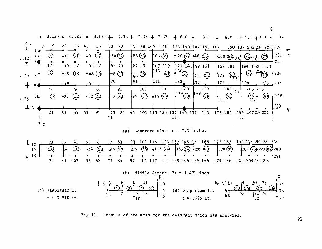
Ft. 1.
3.125
T
1 2
3
7.25 6
t 8
1 7.25
-:1..13
.t13 14
T 15
I- 8.125+ 8.125 + 8.125 + 7.33 -+- 7.33 + 7.33 + 6.0 + ~ I
8.0 ..j.- 8.0 -t5.5 +5.51 ft
e: 16 23 36 43 56 63 78 85 98 105 118 125 140 147 160 167 180 187 20L 2(E 2221 229 .. G) 24 @ ~4 <U 64@ 86@ 106 0 126 § ~a® 168 &88 ~l( @ 230 Y
231 ~
17 25 37 45 57 65 79 87 99 107 119 127 .... 141 49 161 169 181 189 an 2U 223
(j) 28 © 480 68@ 90@ 110
(@ 130® 52 ® ~72 @92
@ ~~ 234.
29 49 70 91 111 32 ..... 53 173 194 225 235
19 39 59 81 1U1 121 i43 163 183 197 205 ?i5
1 @ 32 © 52@ ,3@ 94 @ tLl4@. 135@ 156 @ @ @) @ 176 118
.238
.... 239 -21
L 41 53 33 61
~ 75 83 95 103 115 123 137 145 157 165 177 185 199 207219 '227 I
IV
_._.£
II
21 33 41 53 61 75 8:3
@ ~4 @ 54 @ ~6@ .A
III
(a) Concrete slab, t = 7.0 inches
~~ 103 115 123 1 7 145 157 165
~6 ® 116@ 138® 158 @ 1 7 185
178@)
199 207 219 227 2
200@ 220@ 39
240
241 22 35' 42 55 62 77 84 97 104 117 124 139 146 159 166 179 186 201 208 22l 228
(c) Diaphragm I,
t = 0.510 in.
(b) Middle Girder, 2t = 1.471 inch
,£ Ii 1 2 j 6 8 11 . 13 63 75
• 4 (j) I CV I G) I@t14(d)DiaPhragmII, 6f9--~+-..s;.~--'7""1 ;L-7+4~"" 76 5 7 9 12 115 6
10 t = .625 in. 72 77
Fig 11. Details of the mesh for the quadrant which was analyzed.

54
I--- 14.0
r-- 5.<*-3.~ 5.5+ 5.5...J 16
176
14.0 ~ Ft.
34 20.32k
20.32k
to. 321<.
0.32k
to.32k ~_. _______ ~~~~~240_7 .. ~22~7~ ____________________ __
177 1 5 199 219 239
t. -. _.
-4
6 .35k 4
6.35k -....
• 6 .J.5k. -5 6.35k
(b)
-6.35k
4 4
6.35k -•• 6 .J.5k 4 --6.35k
(d)
.... +20.32k 5.0Sk
4
... 4
-...
-
•• -...
4
-
-..-
.....
...
....
. ......
.....
'''' t
.. !"
~ !:
i I
-. 4
~!"
~:
(a)
5.0Sk
S.OSk
5.0Sk 5.0Sk
5.0Sk
5.0Sk
5.0Sk
-5.08k
-4
-3.S1k 4
-3.81k -U -3.8,lk 4 --3.81k
(c)
---3.81k
• -3.Slk -4 -3.fll.k -3.81
(e)
to.32k
... ... 4
-4
... ....
t '. ~
- ....
Fig 12. HS20 truck loading and the equivalent 4 loading cases.
4
•
t.. I
I
4.
•
J.. 1.0
T 6.0
lO.25 T t 3.75
3.5 :l.
2.5 T

55
bridge deflections and the longitudinal stresses. However, it may have a
significant effect on the transverse bending moments of the concrete slab.
Practically, this is not significant since this loading case is not expected to
be the one which produces the maximum transverse slab moment. Such maximum
moment which may govern the design of the slab usually occurs locally under
the heaviest single wheel load when it is located at the middle of the spacing
between the main girders.
A computer listing of the input data for the four load cases is included
in the Appendix under problem numbers 301, 302, 303, and 304. The results on
the portions of the deck which were not considered in the analysis were obtained
from the results given on the analyzed quadrant by using the conditions of
symmetry and anti-symmetry tabulated in the summary. This procedure is out
lined below.
From the results obtained for the quadrant analyzed under one of the
four applied load cases, the corresponding results on an adjacent quadrant can
be obtained by applying the boundary condition at the plane separating the two
quadrants and by noting that
(1) for symmetric load cases, deflections, normal stresses, and bending moments are symmetric while shearing forces are anti-symmetric, and
(2) for anti-symmetric load cases, deflections, normal stresses, and bending moments are anti-symmetric while shearing forces are symmetric.
By this procedure the results on one half of the structure are obtained.
The results on the remaining half of the structure can be obtained from
the known results on the first half by again considering. the symmetric and
anti-symmetric conditions at the plane separating the two halves.
Discussion of the Results. The deflections at the central transverse
section of the middle span are shown in Fig 13, and the deflections along the
top of girder No. 2 are shown in Fig 14. A comparison of the deflections of the
discrete-element analysis (solution 1) with those of the analysis by the pre
sent method (solution 1) indicates that, in general, the magnitudes of the
deflections obtained by the discrete-element method are greater than the cor
responding values obtained by the present method of analysis. The twisting
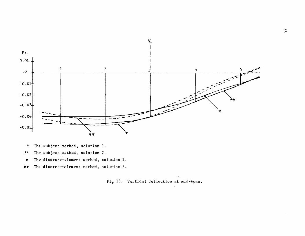
Ft.
0.01
.0
'::0.01
-0.02
* ** •
••
The
The
The
The
... _--
subject
subject
1
--
method,
method,
discrete-element
discrete-element
<t.
2 I 3 4
-----~-
•• • solution l.
solution 2.
method, solution l.
method, solution 2.
Fig 13. Vertical deflection at mid-span.

0.02 { .. ....
* ** ,
0.01
0.0
-0.01
-0.02
-0,03
-0.04
':"0 .. 05
* The subject method, solution 1.
** The subject method, solution 2.
.. The discrete-element method, solution 1 .
.... The discrete-element method, solution 2.
£ I
Fig 14. Vertical deflections at girder No.2.
.. { .... * ** ,

58
deformations are also greater in the discrete-element analysis than in the
finite element analysis. These differences may be due to
(1) completely neglecting the longitudinal slab stiffneas in the zones of negative bending moment in the discrete-element analysis (solution 1),
(2) neglecting the torsional stiffness of the longitudinal beams and of the diaphragms in the discrete-element analysis,
(3) including excessive torsional stiffness in the equivalent rectangular sections in the finite element analysis (solution 1), or
(4) the basic difference between the discrete-element model and the idealized finite element structure as well as the differences in the techniques and assumptions in each case.
To evaluate the effect of the first of these factors, the deck was re
analyzed by the discrete-element method with a composite section stiffness in
the zones of negative bending moment as well as in the zone of positive bending
moment. The slab modulus of elasticity in the negative moment zones was assumed
to be reduced by 80% as in the finite element analysis so that a 20% effective
composite slab was considered in these zones. This analysis is identified as
the discrete-element solution 2, and it results in the deflections shown in
Figs 13 and 14. The results are very close to those computed by the finite
element analysis (solution 1) in the vicinity of the loading, but the twisting
deformations are still greater than those obtained by the finite element method.
To evaluate the effect of the second or third factors, the deck was re
analyzed by the present method using equivalent rectangular sections for the
main beams and the diaphragms with equivalent torsional stiffness as well as
the bending stiffness. This analysis is identified as the finite element
analysis (solution 2) and uses orthotropic materials with a modulus of rigidity
G o
to give the required torsion~l stiffness in the equivalent rectangular sec-
tions. The modulus of elasticity and Poisson's ratio in the longitudinal di-
rection (X-direction) of the beam are the same as for solution 1. The modulus
of elasticity and Poisson's ratio in the Y-direction are calculated from the
relations
G = o
E E x Y
E + E (1 + 2v ) x Y xy
and v E yx x
v E ~y

in which all the terms are as previously defined in Chapter 2. The required
value of G is computed from the relation o
G K GK o e a
in which G is the modulus of rigidity of the actual material and K e
and
59
K a
are the torsional constants for the equivalent rectangular section and for
the actual section, respectively.
An approximate value for
as
K e
and K a
can be computed for each section
in which band t are the length and the thickness, respectively, of the
composing parts of the cross section.
The values used in the analysis for the original material were
E 4.32 (10)9 lb/ft2
'J = 0.3
G E
2(1 + 'J)
For the main girders,
Therefore,
K = a
K e
G 0
E y
'J yx
=
=
=
5.6 in3
38.6 in3
5.6 X 1.662
2.650 (10)8
0.0184
1.662 (10)9 lb/ft2
(10)9 / 38.6 = 2.413 (10)8 Ib/ft2
1b/f/

60
for the diaphragms,
K 1.43 in 3
= a
K 1.00 in 3 e
Therefore,
G 1.115 (10)9 lb/ft2
a
E 1.900 (10)9 lb/ft2
y
v = 0.1319 yx
A computer listing of the input data for the finite element analysis (solution
2) is included in the Appendix under problem numbers 30l-A, 302-A, 303-A, and
304-A.
As shown in Figs 13 and 14, the results of solution 2 by the finite ele
ment method indicate greater twisting deformations and vertical deflections in
the central span than those observed in solution 1. In the outer spans the
two solutions give approximately the same deflections. From the deflections
shown in Figs 13 and 14, the following points can be made:
(1) The discrete-element analysis (solution 2) gives slightly different twisting deformations from those of solution 2 by the present method and considerably different vertical deflections in the central span. The difference in the twisting deformations is consistent with the omission of the torsional stiffness of the beams in the discreteelement analysis. The differences in the vertical deflections may be the result of the basic differences in the two Dlethods which were described earlier. In addition to the increased tHisting deformations observed in solution 2 by the present method" a significant increase in the vertical deflections under the loads is observed even though the bending stiffness of the composing members is the same for both solutions. This indicates that the torsional stiffnesses of the beams affect not only the twisting deformations of the deck but also its overall stiffness.
(2) The two finite element solutions give approximately the same deflections in the outer spans, which indicates that the effect of twisting deformations is rapidly be,ing damped out, possibly due to the effect of the diaphragms. This is emphasized by the fact that the stresses given by the two solutions at the interior supports and at the outer

61
spans are only slightly different. Another contributory factor is the shear deformations of the main beams in the central span where relatively heavy shearing forces exist. This factor may be partially the cause of the larger vertical deflections given by solution 2 in the loaded zone.
The average slab longitudinal stresses at the central section obtained by
the four solutions are shown in Fig 15. There is good agreement between the
four solutions in the vicinity of the load; however, at the unloaded exterior
beam, stresses of much smaller magnitude are given by the discrete-element
solutions than by the finite element solutions. This difference could be
attributed to the twisting deformations. The average slab longitudinal stresses
of the two finite element solutions show very small differences (the maximum
difference is 3% of the largest value).
The longitudinal slab bending moment at the central section is shown in
Fig 16. The two discrete-element solutions and solution 1 by the present
method give results that differ within a small range. The differences between
these three solutions are less visible here than in the cases of deflections
and average longitudinal axial stresses. Solution 2 by the present method
gives considerably higher values for the bending moments than those given by
solution 1 by the same method. At the section of maximum bending moment, an
increase of 36% is shown. However, the increase of the maximum total longi
tudinal slab stress (including slab bending effect) at the same section is
only 16%. This is due to the small variation of the average slab stress.
Example 3. Box Girder Bridge
A box girder bridge continuous over two spans was analyzed by Scordelis
(Ref 19) using three different methods for the analysis of such structures.
The same box girder is analyzed here to compare the results with those obtained
in Ref 19. The three methods described and used in the analysis of Ref 19
are summarized here.
The Folded-Plate Method. This method is based on the elasticity analysis
of folded plates and is described in detail in Refs 25 and 26 and summarized in
Ref 19. It is a combination of a displacement (stiffness) and a force (flexi
bility) method and is limited to box girders or folded plates which are simply

* **
• ••
* ** • ••
-28220 -35400 -36500 -44500 -40000 -32100 -25400 -22850 -16650 -13530 -10000
- 27900 -35200 -35800 -43150 -38800 -32100 -24200 -21800 -16150 -13490 -10800
- 36200 - 40600 - 33600 - 16900 - 1800 - 32800 - 37600 - 31200 - 15300 - 1100
**
~--=------
------------ - - - --=-':.'-----____ 1
The
The
The
The
~
subject method, solution 1.
subject method, solution 2.
discrete-element method, solution 1.
discrete-element method, solution 2.
2 Fig 15. Average slab longitudinal stresses (lb/ft )
at the central section.
0\ N

** Lf-ft ft
3000 ~~
2000
1000 ~
0
* The subject method, solution 1.
** The subject method, solution 2.
~ The discrete-element method, solution 1.
~~ The discrete-element method, solution 2.
Fig 16. Longitudinal slab bending moment at the central section.

64
supported at their extreme ends. All the plates are assumed to be rectangular
and to have the same length and support conditions. Transverse diaphragms with
infinite in-plane stiffness and complete out-of-plane flexibility are assumed
at all the supports. Each plate is assumed to be of constant thickness and of
the same isotropic, homogeneous material throughout its length.
This method may be considered the best solution for this kind of problem.
However, its application is limited to rectangular configurations and special
boundary conditions. There are also thickness and material limitations.
The Finite-Segment Method. This method is described in Ref 19 and is
based on the ordinary theory of folded plates. In the solution, each plate
element is divided longitudinally into a finite number of rectangular segments.
Compatibility and equilibrium conditions are satisfied at points along the four
edges of each segment. Thus, the accuracy of the results increases as the
number of segments increases. This method has all the limitations of the folded
plate method except the condition of simply supported extreme ends.
The Finite Element Method. The finite element method med is described
in Ref 19. It uses a rectangular element with six degrees of freedom at each
corner. These degrees of freedom are three translational ani: three rotation
al degrees. The solution has good capabilities and flexibility of support
conditions. It is limited, however, to rectangular assemblages with the as
sumption that, within each element, the thickness is constant and the material
is isotropic and homogeneous.
The box girder bridge is shown in Fig l7(a). It is symnetric about the
vertical plane through the middle support, and the loads are also symmetric
about this plane. Transversely, the bridge consists of three cells, as shown
in Fig l7(b), and the loads are ~oncentrated on the outer right girder. In
the solutions by Scordelis, each load of 1000 pounds was assumed to be distrib
uted over a length of 1.0 ft in the longitudinal direction. Because of its
symmetry, only one-half of the bridge was considered for analysis. Fig l7(c)
shows the half which was analyzed and the boundary conditions. Longitudinally,
six equal divisions were used, while transversely, each plate was taken as one
division. Thus, the total number of elements used is 60. The details of this
mesh, designated as mesh 1, are shown in Fig 18. Another finer mesh, designated

A
I'"
Diaphragm ~ 1000 Ib Diaphragm 1000 Ib Diaphragm
30 '
E =
8"
I ...
B
"'1" 30' B
"I'" 30 ' ... 1 ...
(a) Longitudinal elevation
3 X 10⁶ psi \I = 0.15
I 411 28 1 - 0" 3 at 9 - c-c
(b) Transverse section
~1000 lb
I i 1-- 6 at 10 1 -0"
(c) Analyzed half, boundary conditions and longitudinal divisions (mesh 1).
__ .1
.. I
1 "I
Fig 17. Example 5. Box Girder Bridge.
30 ' "I C
1000 lb
T 3' - 0" c-c
~
C
65

66
3 2D 29 46 ·55 72 8 98 107 124 133 150 l'
5 ® 31 @ 57 @ 83 @ 109 @ 135 @ 22 34 48 60 74 86 100 112 126 138 152
8
10 ® 36 @ 62 @ 88 @ 114 @ 140 @ 24 39 50 65 76 91 102 117 128 143 154
13
15 @ 41 @ 67 ® 93 @ 119 ® 145 @
18 26 44 52 70 78 96 104 122 130 148 156
t Z (a) Top slab t = E 1/2"
20 29 46 55 72 81 98 107 124 133 150
~l ~ /28 ? /54 ~ j80 ~ 1106 ~ jm ~ X 19 27 45 53 71 79 97 105 123 131 149
(b) Girder 12 t = 8"
Z 19 -. I 45 53 71 79 97 105 123 131 149
1
4 CD 30 @ 56 @ 82 @ 108 @ 134 ® 21 32 47 58 73 84 99 110 125 136 151
6
9 0 35 © 61 @ 87 @ 113 @ 139 @ 23 37 49 63 75 89 101 115 127 141 153
11
14 G) 40 @ 66 @ 92 @ 118 0 144 @
16 t X 25 42 51 68 77 94 103 120 129 146 155
(c) Bottom slab t = 5 1/2"
Fig 18. Details of the mesh used (mesh 1).
9
161
164
166
169
171
174
159
158
157 ..
Y
157 Y ~
160
162
165
167
170
172
67
as mesh 2, was used in the vicinity of the load to study the stresses with more
precision. The details of mesh 2 are shown in Fig 19. This local study of
stress was conducted by using the displacements determined by mesh 1 on the
boundaries of mesh 2 and applying them as boundary conditions for the portion
of the bridge shown in Fig 19(a). The displacements of some of the boundary
points of mesh 2 were interpolated from the output displacements of mesh 1.
The analysis of Ref 19 used two meshes for the finite element method and
two meshes for the finite-segment method. In the finite element method, mesh
1 used ten elements transversely (one on each plate) and 14 divisions longitu
dinally, thus using a total of 140 elements on the analyzed half of the bridge.
Mesh 2 was longitudinally the same as mesh 1 but transversely more refined in
the loaded cell, where two elements were used on the outer right girder and
three elements on both the top slab and the bottom slab. Thus, the total num
ber of elements of mesh 2 was 210. In the finite-segment method, two meshes
were used, transversely similar to the finite element meshes but using 13 di
visions longitudinally instead of 14. Therefore, 130 segments and 195 seg
ments were used for mesh 1 and 2, respectively.
In order to represent the load distribution over a 1.0-ft length, the
element widths on both sides of the midspan section were taken equal to 0.5 ft
in the finite element solutions. In the finite-segment solutions, the width
of the central segments was taken equal to 1.0 ft. In the present analysis,
this distribution over a 1.0-ft length was ignored, and the load was treated
as a concentrated force. The data for both meshes are included in the Appendix,
together with a complete output for mesh 1.
Comparison of Results
Some of the results given by Ref 19 are presented here, together with the
corresponding values obtained by the present analysis. The folded-plate meth
od, the best available solution, is taken as the basis for comparison. The
results of the other two methods of Ref 19 are listed to show their accuracy
relative to that of the present method.
Deflections. The vertical deflections obtained by the present method,
mesh 1, along the top of the four girders are plotted in Fig 20. All the

68
'" '"
z
~ ~~ ....--- 20' ... 1--10,--1-- 10 '-1, ....... 1---- 20' __ "'oI"k9 1_4
11
(a) Analyzed portion and coordinate axes.
1 z 2 3 4 5 h 7 8
10 (Dn @12 (2)13 ®
15 16 17 18 19 20 21 22
G)25 (b) Bottom slab.
24 (026 (j)27 ®
29! X 30 31 32 33 34 5 36
9
14
23
28
37
4 3 44 l 5 46 47 48 ~9
@39 @40 @41 , ~ l~~ (c) Girder R2. 38
29 30 31 32 33 34 35 36 37
71 72 73 74 75 76 77 78 79
66 <tP 67 @68 @69 (@ 70
58 59 60 61 62 63 64 57 65
(d) Top slab
52 @53 Q9 54 @lS5 I~ 56
4 3 44 45 46 47 48 49 - 51
y ..
Fig 19. Local mesh 2 for studying the stresses in the vicinity of load.

69
o - Folded plate method 'V - Finite element, mesh 2 o - Finite segment, mesh 2 . - Finite element, mesh I-. - Finite segment, mesh 1
* - The present method, mesh 1
**- The present method, mesh 2 L2 L1 R1 R2
1-1 "0 Distance y in Feet aJ 0
"0 ..c 1-1 .j.J
52.5 'M aJ 7.5 12.5- 17.5 22.5 27.25 30.0_ c..? ~
0 0.31 0.69 1.13 1.57 1. 93 2.04 2.01 1. 79 1.46 1.07 0.65 V 0.30 0.66 1.08 1.52 1.85 1.98 2.02 1.77 1.42 1.04 0.63
N 0 0.32 0.71 1.17 1.63 1.99 2.16 2.08 1.85 1.50 1.09 0.66
0:: • 0.30 0.65 1.07 1.50 1.84 1.95 1.92 1.72 1.39 1.01 0.63 • 0.30 0.68 1.12 1.56 1. 90 2.05 1.99 1. 79 1.47 1.08 0.66
* 0.32 0.68 1.11 1.56 1.89 2.02 1.97 1. 78 1.44 1.06 0.65
** 1.56 1.90 2.05 2.00 1.77 0 0.14 0.32 0.51 0.69 0.81 0.85 0,87 0.85 0.75 0.58 0.36 V 0.13 0.30 0.49 0.65 0.77 0.80 0.82 0.80 0.71 0.55 0.35 0 0.15 0.32 0.51 0.68 0.80 0.85 0.87 0.84 0.74 0.57 0.36
~ 0.13 0.28 0.47 0.63 0.75 0.79 0.80 0.78 0.68 0.53 0.34 0:: 0.13 0.30 0.48 0.64 0.75 0.79 0.81 0.80 0.71 0.56 0.35 0.14 0.32 0.51 0.69 0.81 0.85 0.87 0.84 0.74 0.58 0.36 0,07 0.15 0.24 0.33 0.39 0.41 0.43 0.42 0.38 0.30 0.19 0.06 0.13 0.21 0.28 0.34 0.37 0.38 0.37 0.34 0.27 0.17
~ 0.06 0.14 0.22 0.30 0.36 0.38 0.39 0.39 0.35 0.28 0.18
....:l • 0.06 0.13 0.21 0.28 0.34 0.37 0.38 0.37 0.34 0.27 0.17 • 0.06 0.13 0.21 0.28 0.34 0.36 0.37 0.37 0.34 0.27 0.17
* 0.07 0.15 0.24 0.33 0.39 0.41 0.43 0.42 0.38 0.30 0.19 0 0.05 0.11 0.17 0.22 0.26 0.28 0.29 0.29 0.26 0.21 0.14 V 0.04 0.09 0.14 0.19 0.22 0.24 0.25 0.26 0.23 0.18 0.12
N 0 0.04 0.09 0.14 0.19 0.23 0.24 0.25 0.25 0.23 0.19 0.12
....:I • 0.04 0.09 0.14 0.19 0.22 0.24 0.25 0.26 0.23 0.18 0.12 • 0.04 0.09 0.14 0.18 0.22 0.23 0.24 0.24 0.22 0.18 0.12
* 0.05 0.11 0.17 0.22 0.26 0.28 0.29 0.29 0,26 0.21 0.14
Fig 20. Vertical deflections (x 104
Ft) along tops of girders.

70
results are tabulated at the same locations used in Ref 19. It is to be noted
that these locations do not match the nodal points of mesh I 2xcept at mid
span. Thus, the values at locations between the nodal points of mesh 1 are
obtained by interpolation. The interpolation process is easy and accurate,
since the displacements in the plane of the girders for the element used should
have parabolic variation. The deflection shapes of all the girders are similar
to those of a beam fixed at one end and hinged at the other. A comparison of
the tabulated values reveals that, in general, the present method gives the
closest agreement with the folded-plate method. It can be noted that the local
mesh gives better agreement with the folded-plate method in the central part
of the mesh. As expected, this improvement in the deflections of the local
mesh does not exist near the boundaries.
Stresses. The longitudinal distributions of the longitudinal axial stres
ses at the top of girder R2, at the right edge of the top slab, and at the
right edge of the bottom slab are shown in Figs 21, 22, and 23, respectively.
The plotted values are those of the present method, and the results of the
other three methods are tabulated for comparison. A procedure of averaging
and extrapolation similar to that used by Ref 19 was used in plotting these
curves. In the present method, this was done simply by drawing a parabola
between three points representing stress values obtained front the two elements
adjacent to the location in question. The two end values on such a parabola
are the stresses at the mid-side nodes of the adjacent elements, and the mid
dle value is the average of the values of the two elements at the common node.
After such a parabola was drawn, the values at the locations in question were
measured. Such parabolas were extended towards the support sides to extrap
olate the values at the supports and near them. The values at the central
section are the averages of the extrapolated values from both sides. Finally,
the values obtained at the required locations were plotted, and the curves
shown were drawn through them. The easiest way to do such interpolation and
extrapolation is the graphical procedure which was used here, although better
ways may exist to reduce such results. Complicated methods of reduction of
results may prove to be of limited advantage.

749.5 530.0 283.0 139.2 - 1.4 -190.3 -537.3 -1275.4 -573.0 -276.3 -151. 1 -86.4 -45.5 -15.0 - 0
600.0 495.0 300.0 149.0 - 9.0 -208.0 -530.0 -1095.0 -588.0 -285.0 -149.0 -80.0 -40.0 -12.0 -f\l 667.4 525.8 304.0 159.1 23.9 -189.3 -497.9 -1252.4 -526.4 -267.9 -116.8 -60.2 -28.3 - 8.3 - 0
600.0 495.0 300.0 149.0 - 4.0 -208.0 -540.0 - 910.0 -572.0 -289.0 -150.0 -83.0 -41.0 -12.0 -A 576.3 482.3 309.7 155.8 - 3.9 - 208.9 -496.8 - 880.6 -527.2 -294.2 -155.7 -81.6 -39.3 -11. 7 -. 650.0 525.0 300.0 135.0 -10.0 -210.0 -570.0 - 886.0 630.0 292.0 -127.0 -74.0 -35.0 -18.0 -*
-199.0 -555.0 -1095.0 -585.0 272.0 - **
l ) 22.5 27.25 30.0 32.75 37.5 42.5 47.5 52.5 57.5 Ft
y = 2.5 7.5 12.5 17 .5
c- Folded plate method '\1- Finite element method, mesh 2 ~ 1000 1bs 0- Finite segment method, mesh 2 l A- Finite element method. mesh 1 . - Finite segment method, mesh 1
J * - The present method, mesh 1 **- The present method, mesh 2 L2 L1 R1 R2
Fig 21. Longitudinal distribution of longitudinal stress 0 y (PSF) in top of girder R2.

1-523
.7 1112. ~I 557.6 -268.7
-540.0 960.01
-580.0 -279.0 -539.1 - 976.2 -567.9 -268.1 1-530.0 - 860.0 -580.0 -281.0 -510.4 - 708.6 -540.9 -301.5 -606.0 816.0 -597.0 -306.0 -549.0 - 997.0 -578.0 -268.0
'\ )
748.9 518.0 283.9 141.5 2.6 -184.4 747.0 526.0 296.0 145.0
~ -198.0
701. 9 507.4 296.9 149.6 -186.9 720.0 520.0 296.0 140.0 6.0 [2.0 578.3 481.5 307.2 151.8 -9.1 -215.3 664.0 526.0 304.0 135.0 4.0 -221.0
-195.0
-144.6 -81.4 -42.4 -17.0 -0
-142.0 -78.0 -39.0 -12.0 -'il -142.0 -73.8 -36.6 -11.1 -0
-147.0 -78.0 -40.0 -12.0 -A -163.1 -86.9 -42.5 -21.6 -. -135.0 -76.0 -37.0 -11.0 -*
-**
I 22.5 27.25 30.0 32.75 37.5 42.5 47.5 52.5 57.5 Ft
y = 2.5 7.5 12.5
c - Folded plate method tJ- Finite element method, mesh 2 o - Finite segment method, mesh 2 It 1000 Ibs
• - Finite element method, mesh 1
! ~ . - Finite segment methoo, mesh 1
! -I * - The present method, mesh 1
** - The present method, mesh 2 I L2 Ll R1 R2
Fig 22. Longitudinal distribution of longitudinal stress cr (PSF) in the right edge of the top slab. y

-836.9 -575 .. 0 -324.3 -164.1 - 7.9 200.8 596.3 987.0 630.5 293.0 154.5 84.3 42.6 18.0 - c -720.0 -578.0 -331.0 -160.0 - 5.0 225.0 609.0 922.0 649.0 320.0 164.0 89.0 44.0 11.0 -'il -784.2 -568.8 -334.9 -167.9 - 4.8 227.8 595.0 1007.3 627.7 320.1 159.4 86.2 42.4 12.8 - 0
-720.0 -578.0 -331.0 -160.0 - 2.0 237.0 581.0 848.0 638.0 327.0 165.0 91.0 44.0 11.0 -.l -650.0 -542.1 -346.4 -170.9 -11.6 243.9 572.6 792.9 607.3 341.8 186.5 99.8 48.9 14.7 - . -735.0 -589.0 -342.0 -153.0 -11.0 251.0 634.0 915.0 670.0 342.0 153.0 87.0 42.0 15.0 -*
J 218.0 626.0 1080.0 665.0 302.0 - **
Y .. 2.5 7.5 12.5
22.5 27.25 30.0 32.75 3.75 42.5 47.5 52.5 57.5 Ft
~ 1000 1bs c - Folded plate method
:
I 'il - Finite element method, mesh 2 o - Finite segment method, mesh 2
.1 t::.- Finite element method, mesh 1 o - Finite segment method, mesh 1 L2 Ll R1 R2 * - The present method, mesh 1
** - The present method, mesh 2
Fig 23. Longitudinal distribution of longitudinal stress 0 (PSF) in the right edge of the bottom slab. y ~
w

74
A comparison of results of stresses reveals that mesh 1 of the present
method gives good agreement with the folded-plate method except under the load
and at the central support where concentrated forces exist. The local mesh
under the load results in a significant improvement in the accuracy of stresses.
Transverse Bending Moments. The transverse bending moment diagrams ob
tained by the present method at midspan are shown in Figs 24, 25, and 26. The
moments were obtained by averaging the values obtained from the adjacent ele
ments at the common points. It should be noted that only the folded-plate meth
od satisfies the condition of moment equilibrium at the joints. Here, the
present method gives fair agreement with the folded-plate method. The improve
ment in accuracy by using a local fine mesh is also notable.
General Remarks. The excellent results for the displacements which were
obtained by the present method using a coarse mesh for the severe loading con
dition demonstrates the superiority in displacement calculations of the quad
rilateral element with eight nodes. This is also expected to be the case if
the triangular element with six nodes were used. This property provides some
flexibility in the solution of large problems where very fine meshes are not
desirable. In other words, a coarse mesh can be used to give fairly good
values of displacements in the whole structure; then, local study of stresses
at the positions of special importance to the designer can be carried out using
finer meshes, as demonstrated in this example.
The case of a single concentrated load without distributed loads is a
theoretical assumption in the case of most shell-type structures. Practically,
distributed loads constitute a major percentage of the total loads on such
structures. It is also known that the accuracy of the stresses obtained by
the finite element solutions for' distributed loads is better than that of the
solutions for concentrated loads, especially near the heavily concentrated
loads. Therefore, even the fact that the stress results of mesh 1 are only
fair is, practically, not a serious problem. The problem may still exist in
cases of shells or similar structures supported by a few slender supports.
For such cases, local refinement of the mesh at such supports either within
the solution of the whole structure or separately is required to obtain accurate
stress evaluation.

I I i1000 1bs
:1 L ~
hooo
: R; 1bs
I L2 11 R2
*
[J - -4.8 'il- -4.4 o - -4.1 ~- -4.4
• - -3.9
* - -3.9
[J ~ Folded plate method 'il - Finite element method, mesh o - Finite segment method, mesh ~ - Finite element method, mesh . - Finite segment method, mesh
* - The present method, mesh 1
** - The present method, mesh 2
4.1 3.6 3.3 3.8 3.1 3.2
--, I
I -l3 .4 -12.8 -13.2 -12.3 -12.1 -1l.5
-39.3 -37.1 -43.5 -37.5 -41.3 -33.9 -35.1
2 2 1 1
-11.6 -11. 2 -13.9 -10.3 1l.5
10.9 -13 .4 -11. 2 10.8 -12.3
1l.2 10.0 9.4
12.4 13.3 15.8 16.7 14.5 12.7 12.1
67.5 44.3 45.4 38.8 42.3 37.9 47.5
- --, -1 I
I I
Fig 24. Transverse distribution of transverse bending moment (lb-ft/ft) in top slab at midspan.
- [J
-\1
- 0
-~ -. -* - **

C/ - Folded plate method \7- Finite element method, mesh 2
-...J
o - Finite segment method, mesh 2 0'
1bs A- Finite element method, mesh 1 . - Finite segment me thod, mesh 1 34.2 - C/ *- The present method, mesh 1
29.0 The present method, mesh 2 - \7
** - 30.9 - 0
~ -7.8 9.0 2S.0 - A
1000 1bs -S.l 8.6 2S.7 - • -9.5 10.7 26.1 - * 3.4 10.2 29.8 - **
R2 3.1 -7.6 10.7
2.8 9.6 -9.2 9.7
3.2 9.9 - 7. 9.5
2.7 9.5 -8. 9.0
2.7 9.3 S.6
I
I L --- L J I
- -- -~
C/ - -3.6 -10.2 -27.7 \7- -3.3 - 9.8 -26.3 o - -3.0 -10.2 -29.8 .- -3.3 - 9.6 -26.8
• - - 2.9 - 9.4 - 28.1
* - - 2. 9 - 8.7 - 23.8 \ - 24.81
Fig 25. Transverse distribution of transverse bending moment (lb-ft/ft) in bottom slab at midspan.

c -'V-o -.. -. -*-
** -
37.9 37.2 39.7 37.3 37.4
I fooo Ibs
1 L Ibs
Folded plate method Finite element method, mesh Finite segment method, mesh Finite element method, mesh Finite segment method; mesh The present method, mesh 1 The present method, mesh 2
31. 5 f- .....:::::.----___ ....
2 2 1 1
c -'V -o -.. -. -* -
3.6 3.2 3.0 3.3 2.9 2.9 -
-50.9 -49.6 -54.3 -49.8 -51.3 -44.0
-34.2 35.6 30.9 34.2 28.7 24.9 26.8
-4.8 -4.2 -4.1
- - -4.3 -3.9 -4.0
-17 .5 -16.9 -16.5
_---r-- -16.7
13.7 13.1 13 • 1 t-- -£----4 __ _
13.0 12.1 11.4
-
-15.3 -14.4
-67.5 -50,0 -45.4 -49.3 -42.3 -38.8 -44.8
Fig 26. Transverse distribution of transverse bending moment (lb-ft/ft) in girders at midspan.
- IJ
-'iJ - 0
- .. - . - * - **


CHAPTER 4. SUMMARY AND CONCLUSIONS
The present method provides the generalities and capabilities of the
finite element for the analysis of bridge decks. In the analysis of such
structures by the finite element method, there are two approaches. The first
approach uses coarse meshes composed of elements with refined stiffness evalu
ation. This approach has the advantage of reducing the amount of input data
and consequently, the effort of preparing and checking such data. The second
approach uses fine meshes composed of elements with relatively less refined
stiffness evaluation and has the advantage of flexibility in geometric ideal
ization which enables the representation of complicated geometry without un
reasonable increase in the solution time. If such complicated geometries are
idealized with refined elements, the increase in solution time counteracts the
advantage gained by using such refined elements. Both approaches are avail
able in the present method. The refined elements are the quadrilateral and
the triangular elements with mid-side nodes while the less refined elements
are the quadrilateral and the triangular elements without mid-side nodes.
Therefore, for economical use of the program, the refined elements can be used
with coarse meshes to idealize bridge decks with simple geometries, such as
box girder bridges, slab type bridges, and beam-slab type bridges, while the
other elements may be used with fine meshes to idealize complicated geometries,
such as bridges with single or double curvature. Combinations of the refined
and the less refined elements may also be used, as shown in Example 2 of
Chapter 3.
The refined elements have s~perior membrane stiffness properties. This
property makes them most suitable for representing parts of bridge decks such
as the girders which mainly support in-plane loadings.
The computer program provides various capabilities for treating load
cases and various output options. The user has the option either to stop the
solution after computing nodal point displacements or to let it continue and
compute the element forces (stresses). This is helpful in cases where a
coarse mesh that gives satisfactory accuracy in displacement computation would
79

80
not have the desirable accuracy in stress computation. In such cases, use of
this option can avoid the time required for computing the stresses of the
coarse mesh, and a local, more precise study of the stresses at particular
locations may be made as illustrated by Example 3 in Chapter 3. However, it
may be possible to have the local mesh refinement within the solution of the
whole structure without major increase in the total number of the mesh nodal
points.
The present method of analysis considerably reduces and simplifies the
required input data by expressing most of such data in the global coordinate
system. With the simplified data input, the data preparation time and the
chances of error are minimized. However, as a result of the global represen
tation of the data, it may be impossible to represent the boundary conditions
of certain complicated cases of support conditions. Although realistic rep
resentations of most boundary cases in practice can be made either directly or
indirectly, this is the most serious limitation of the solution.
The present use of the six-degree-of-freedom nodal point system is essen
tial in general solutions. The five-degree-of-freedom analysis (Ref 11) may
give good results, especially in cases of smoothly curved shells; but in gen
eral, it is an insufficient representation of the shell prob].em and must be
used with full understanding of its limitations. This is particularly impor
tant at plate intersections, such as the slab-girder junctions of bridges,
where the constraint of one rotation component in the five-degree analysis may
cause considerable error. The problem arising from the use of five-degree-of
freedom elements in a six-degree-of-freedom system was solved by omitting the
dependent equations. The new procedure described for such mnission is a gen
eral one and can be used in similar problems in structural analysis.
The present method g~ves good results when compared to existing methods
of analysis of bridge decks. In addition, it has more general features than
any of the other methods discussed.
Scordelis' finite element method (Ref 19) offers a good solution for
bridge decks with rectangular configuration. The accuracy of this method of
analysis may be slightly better than the analysis using the less-refined quad
rilateral element of the present method. The two other methods of Ref 19 are
limited to box girder type bridges.

81
The discrete-element method of analysis (Refs 1, 2, and 3) is a quick and
accurate solution for slab-type bridge decks. For beam and slab-type bridges,
the method still gives a good approximation if proper stiffness values are
assigned to the beams. In cases of decks with narrowly spaced main beams and
enough diaphragms to prevent excessive beam rotations, the common practice for
selecting the composite section stiffness may be an accurate representation.
In cases of widely spaced beams where considerable beam rotations exist, however,
such composite section stiffness may not be a proper representation. One of
the most serious limitations of the discrete-element analysis is the require
ment of using a regular mesh which usually requires changes in the deck di
mensions and in locations of supports and diaphragms.
In conclusion, it can be safely stated that the present method of analysis
of bridge decks as shell-type structures offers a relatively good general solu
tion with considerable flexibility. It can be used successfully to analyze a
wide variety of bridges on rigid or elastic supports.

!!!!!!!!!!!!!!!!!!!"#$%!&'()!*)&+',)%!'-!$-.)-.$/-'++0!1+'-2!&'()!$-!.#)!/*$($-'+3!
44!5"6!7$1*'*0!8$($.$9'.$/-!")':!

REFERENCES
1. Stelzer, C. Fred, and W. Ronald Hudson, "A Direct Computer Solution for Plates and Pavement Slabs," Research Report No. 56-9, Center for Highway Research, The University of Texas, Austin, October 1967.
2. Endres, Frank L., and Hudson Matlock, "An Algebraic Equation Solution Process Formulated in Anticipation of Banded Linear Equations," Research Report No. 56-19, Center for Highway Research, The Universi ty of Texas, Austin, January 1971.
3. Panak, John J., and Hudson Matlock, "A Discrete-Element Method of Analysis for Orthogonal Slab and Grid Bridge Floor Systems," Research Report No. 56-25, Center for Highway Research, The University of Texas, Austin, 1972.
4. Abdelraouf, M. R. S., "Finite Element Analysis of Shell-Type Structures," Ph.D. Dissertation, The University of Texas, Austin, August 1971.
5. Zienkiewicz, O. C., The Finite Element Method in Structural and Continuum Mechanics, McGraw-Hill Publishing Co., Ltd., London, 1967.
6. Turner, M. J., R. W. Clough, H. C. Martin, and L. J. Topp, "Stiffness and Deflec tion Analysis of Complex Struc tures," Journal of Aeronautical Science, Vol 23, No 9, 1956.
7. Clough, R. W., "The Finite Element Method in Plane Stress Analysis," Proceedings, 2nd. Conference on Electronic Computations, American Society of Civil Engineers, September, 1960.
8. Melosh, R. J., "A Stiffness Matrix for the Analysis of Thin Plates in Bending," Journal of the Aerospace Science, Vol 28, 1961, pp. 34-42.
9. Adini, A., "Analysis of Shell Structures by the Finite Element Method," Ph.D. Thesis, University of California, Berkeley, 1961.
10. Clough, R. W., and J. L. Tocher, "Analysis of Thin Arch Darns by the Finite Element Method," Proceedings, Symposium on Theory of Thin Arch Dams, University of Southampton, Pergamon Press, 1965.
11. Johnson, C. P., "The Analysis of Thin Shells by a Finite Element Procedure," Structural Engineering Laboratory Report N~ 67-22, University of California, Berkeley, 1967.
12. Felippa, C. A., "Refined Finite Element Analysis of Linear and Nonlinear Two-Dimensional Structures," Structural Engineering Laboratory Report No. 66-22, University of California, Berkeley, 1966.
83

84
13. Carr, J. A., "A Refined Finite Element Analysis of Thin Shell Structures Including Dynamic Loadings," Structures and Materials Research Report No.SESM-67-9, University of California, Berkeley, 1967.
14. Bonnes, G., G. Dhatt, Y. Giroux, and L. Robichaud, "Curved Triangular Elements for the Analysis of Shells," Proceedings, 2nd. Conference on Matrix Methods in Structural Mechanics, Wright-Patterson Air Force Base, Columbus, Ohio, 1968.
15. Dhatt, G., "Numerical Analysis of Thin Shells by Curved Triangular Elements Based on Discrete-Kirchoff Hypothesis," Proceedings, Symposium on Application of Finite Element Methods in Civil Engineering, Vanderbilt University, 1969.
16. Cowper, G. R., G. M. Lindberg, and M. D. Olson, "A Shallow Shell Finite Element of Triangular Shape," International Journal of Solids and Structures, Vol 6, No 8, August 1970.
17. Ahmad, S., B. M. Irons, and O. C. Zienkiewicz, "Curved Thick Shell and Membrane Elements with Particular Reference to Axi-Symmetric Problems," Proceedings, 2nd Conference on Matrix Methoc,s of Structural Analysis, Wright-Patterson Air Force Base, Columbu~:, Ohio, 1968.
18. Clough, Ray W., and C. P. Johnson, "Finite Element AnalysiS of Arbitrary Thin Shells," a paper prepared for presentation at ACI Symposium on Concrete Thin Shells, New York, N. Y., April 16-17, 1970.
19. Scordelis, A. C., "Analysis of Continuous Box Girder Bridges," Structures and Materials Research Report N~ SESM-67-25, University of California, Berkeley, 1967.
20. Clough, R. W., and J. L. Tocher, "Finite Element Stiffness Matrices for the Analysis of Plate Bending," Proceedings, Conference on Matrix Methods in Structural Mechanics, Air Force Institute of Technology, Wright-Patterson Air Force Base, Columbus, Ohio, Oetober 1965.
21. Timoshenko, S., and S. Woinowsky-Kreiger, Theory of Pla::es and Shells, 2nd Edition, McGraw-Hill, New York, 1959.
22. Hudson, W. Ronald, and Huds~n Matlock, "Discontinuous O:rthotropic Plates and Pavement Slabs," Research Report NC\ 56-6, Centl::!r for Highway Research, The University of Texas, Austin, May 1966.
23. The American Association of State Highway Officials, Standard Specifications for Highway Bridges, 9th Edition, Washington, D. C., 1965.
24. Scordelis, A. C., and K. S. Lo, "Computer Analysis of Cylindrical Shells," Journal of the American Concrete Institute, Vol 61, No 5, 1964.

25. Scordelis, A. C., "Analysis of Simply Supported Box Girder Bridges," Structures and Materials Research Report No.SESM-66-l7, University of California, Berkeley, 1966.
26. Lo, K. S., "Analysis of Cellular Folded Plate Structures," Ph.D. Thesis presented to the Division of Structural Engineering and Structural Mechanics, University of California, Berkeley, January 1967.
85

!!!!!!!!!!!!!!!!!!!"#$%!&'()!*)&+',)%!'-!$-.)-.$/-'++0!1+'-2!&'()!$-!.#)!/*$($-'+3!
44!5"6!7$1*'*0!8$($.$9'.$/-!")':!
APPENDIX
SELECTED COMPUTER OUTPUT

!!!!!!!!!!!!!!!!!!!"#$%!&'()!*)&+',)%!'-!$-.)-.$/-'++0!1+'-2!&'()!$-!.#)!/*$($-'+3!
44!5"6!7$1*'*0!8$($.$9'.$/-!")':!

PROGRAM SHELL 6 - MASTER DECK - ABDELRAOUf. MATLOCK REViSioN DATE SHELL 6 REPORT CODED BY ABDELRAOUf APRIL 16. 1911 EXAMPLE PROBLEMS
PROB 1- A CANTILEVER BEAM. MESH (II
TABLE 1- GENERAL PROBLEM INfORMATION
NUM Of ELEMENTS NUM Of POINTS NUM Of LOAD CASES ELEMENT fORCES REQUIRED C I • YES
TABLE 2- MATERIAL ELASTIC PROPERTIES
NUMBER Of CARDS fOR THIS TABLE
<; 28
1 1
6 MAY 1911
MAT TYPE
X DIRECTION EX VXY
Y DIRECTION EY VYX
SHEAR MODUL;US G
( . 3.000E·03
ASSUMED VALUES
2.500E-Ol
TABLE J- NODAL POINT COORDINATES
NUMBER Of CARDS fOR THIS TABLE 2
fROM THRU INCR PT PT
STARTING POINT COORDINATES X Y Z
2.500E-OI*
END POINT COORDINATES X Y Z
I :)
26 28
5 O. 5 O.
O. O.
o. O. 2.000E'00 O.
I.OOOE.OI O. 1.000E'01 2.000E'00
TABLE 4 - ELEMENT PROPERTIES
!\lUMBER Of CARDS fOR THIS TABLE 2
fROM THRU INCR MAT ANGLE THICKNESS ELEMENT NODES ELMT ELMT TYpE
O. 5.000E-Ol I 6 8 3 4 7 5 2 5 21 26 28 23 24 27 25 22
TABLE 5- ELEMENT LOADS
NONE
TABLE 6- BOUNDARY CONDITIONS
NUMBER Of CARDS fOR THIS TABLE 3
fROM TMRu INCR CASE CONDo •• BOUNDARY VALUES
1--- PT PT )I. Y Z )I. Y 1
1 3 2 I 0 -0. -0. -0. Z -0 -0 I I -0. -0. -0. 1 3 I 2 I -0. -0. -0.
* CASE. I fOR SPECifiED DISPLACEMENTS OR SPRING RESTRAINTS IN DIR. Of AXES CASE & 2 fOR SPECifiED SLOPES OR ROTATIONAL RESTRAINTS ABOUT THE AXES
•• CONDITION 0 fOR NO SPECifiCATION CONDITID~ • I fOR SPEC. DISPLACEMENT OR SLOPE CONDITIO~ 2 fOR ELASTIC RESTRAINTS
APPLIED LOADINGS
CONCENTRATED fORCES OR MOMENTS - GLOBAL COORDINATES
LOAD CASE
NUMBER Of CARDS fOR THIS TABLE
ELEMENT LOADS TO BE ADOED I 1 • YES
fROM THRU INCR PT PT
fORCES IN DIRECTIONS
26 27
28 21
X Y
I 4.680E.00 O. -0 4.680E.00 O.
2
-0
MOMENTS ABOUT AXES z
1.275E·01 O. 7.215E.Ol O.
X Y
O. O.
o. O.
z
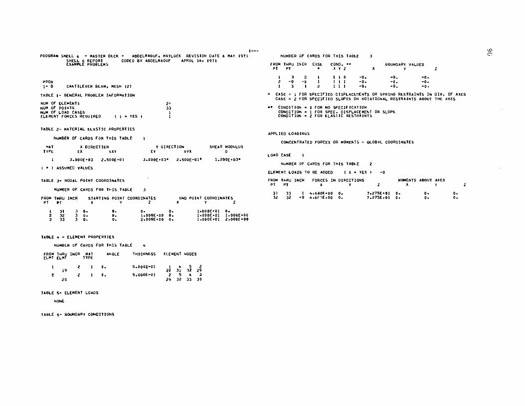
PROGRAM SHELL 6 - MASTER DECK - ABDELRAOUf. MATLOCK REVISION DATE SHELL 6 REPORT CODEO BY ABDELRAOUf APRIL 16. 1971 EXAMPLE PROBLEMS
PROB 1- B CANTILEVER BEAM. MESH (21
TABLE 1- GENERAL PROBLEM INfORMATION
NUM Of ELEMENTS NUM Of POINTS NUM Of LOAD CASES ELEMENT fORCES REQUIRED ( I ~ YES
TABLE 2- MATERIAL ELASTIC PROPERTIES
NUMBER Of CARDS fOR THIS TABLE
2n 33
1 I
6 MAY 1971
MAT TYPE
X DIRECTION EX VXY
Y OIRECTION EY VYX
SHEAR MODUl;US G
2.500E-OI J.000E·03-
(- ASSUMED VALUES
TABLE J- NODAL POINT COORDINATES
NUMBER Of CARDS fOR THIS TABLE J
fROM THRU INCR PT PT
I 2 3
31 32 33
J O. 3 O. 3 O.
STARTING POINT COORDINATES X Y Z
O. O. o.
O. O. I.OOOE.OO O. 2.000E.00 o.
TABLE 4 - ELEMENT PROPERTIES
NUMBER Of CAHDS FOR THIS TABLE 4
2.500E-0I-
END POINT COORDINATES X Y Z
1.000E·01 I·OOOE·OI 1.000E·01
O. I.OOOE·OO 2.000E·00
fROM THRU INCR MAT ANGLE THICKNESS ELEMENT NODES ELMT ELMT TYPE
2 O. 5.000E-01 I 4 5 2 19 28 31 32 29
2 2 O. 5.000E-OI 2 5 6 3 20 29 32 33 30
TABLE 5- ELEMENT LOADS
NONE
TABLE 6- BOUNDARY CONDITIONS
1---NUMBER Of CARDS FOR THIS TABLE 3
fWOM THRU INCR CASE CONDo -- BOUNDARY VALUES PT PT X Y Z X Y Z
I 3 2 I 0 -0. -0. -0. 2 -0 -0 1 I -0. -0. -0. I 3 I 2 I -0. -0. -0.
CASE ~ 1 fOR SPECifIED DISPLACEMENTS OR SPRING RESTRAINTS IN DIR. Of AXES CASE = 2 FOR SPECifiED SLOPES OR ROTATIONAL RESTRAINTS ABOUT THE AXES
-- CONDITION CONDIT ION CONDIT ION
APPLIED LOADINGS
o fOR NO SPECifiCATION I fOR SPEC. DISPLACEMENT OR SLOPE 2 fOR ELASTIC RESTRAINTS
CONCENTRATED fORCES OR MOMENTS - GLOBAL COORDINATES
LOAO CASE
NUMBER OF CARDS fOR THIS TABLE 2
ELEMENT LOADS TO BE ADDED ( I = YES -0
FROM THRU INCIi PT PT
fORCES IN OIRECTIONS X Y z
MOMENTS ABOUT AXES X
31 32
33 32
I 4.680E.00 O. -0 4.6E1E.00 O.
7.275E'01 O. 7.275E.OI O.
O. O.
O. O.
z
\0 0

PROGRAM SHELL 6 - MASTER DECK - ABDELRAOUF. MATLOCK REViSiON DATE 6 MAY 1971 SMELL 6 REPORT CODEO BY ABDELRAOUF EXAMPLE PROBLEMS
PROB 1- C CANTILEVER BEAM. MESM 131
TABLE 1- GENERAL PROBLEM INFORMATION
NUM OF ELEMENTS NUM OF POINTS NUM OF LOAD CASES ELEMENT FORCES REQUIRED I I = YES
TABLE 2- MATERIAL ELASTIC PROPERTIES
NUMBER OF CARDS FOR TMIS TABLE
10 33
I I
APRIL 16. 1971
MAT TYPE
It DIRECTION Y DIRECTION SMEAR MODULUS G EX VltY EY VYX
3.000E-03 2.500E-OI 3.000E-03- 2.500E-0I-
(- ASSUMED VALUES
TABLE 3- NODAL POINT COORDINATES
NUMBER OF CARDS FOR TMIS TABLE 2
FROM THRU INCR PT PT
STARTING POINT COORDINATES END POINT COORDINATES X Y Z It Y Z
I 3
TABLE
FROM ELIOT
2
TABLE
31 33
6 O. 6 O.
O. O.
4 - ELEMENT PROPERTIES
NUMBER OF CARDS FOR TMIS
TMRU INCR MAT ANGLE ELMT TYPE
2 O. 9
2 O. 10
5- ELEMENT LOADS
NONE
TABlE 6- BOUNDARy CONDITIONS
NUMBER OF CARDS FOR TMIS
TABLE
TABLE
o. O. 2.000E_00 O.
4
TMICKNESS ELEMENT
5.000E-OI I 7 25 31
5.000E-0I 7 9 31 33
3
NODES
3 27
3 27
1.000E'01 O. I.OOOE.OI 2.000E.00
4 5 2 28 29 26
8 6 5 32 30 29
1---FROM THRU INCR CASE CONO. -- BOUNOARY VALUES
PT PT X Y Z X Y Z
I 3 2 I 0 -0. -0. -0. 2 -0 -0 I I -0. -0. -0. I 3 I 2 I -0. -0. -0.
CASE. I FOR SPECIFIED OISPLACEMENTS OR SPRING RESTRAINTS IN DIR. OF AXES CASE z 2 FOR SPECIFIED SLOPES OR ROTATIONAL RESTRAINTS ABOUT TME AxES
CONDITION 0 FOR NO SPECIFICATION CONDITION = I FOR SPEC. DISPLACEMENT OR SLOPE CONDITION 2 FOR ELASTIC RESTRAINTS
APPLIED LOADINGS
CONCENTRATED FORCES OR MOMENTS - GLOBAL COORDINATES
LOAD CASE
NUMBER OF CARDS FOR THiS TABLE
ELEMENT LOADS TO BE ADDED ( I = YES
FROIO TMRU INCR PT PT
FORCES IN OIRECTIONS
31 32
33 32
X Y
I 4.680E.00 O. -0 4.680E.00 O.
2
-0
MOMENTS ABOUT AXES Z
7.275E'01 O. 7.275E-OI O.
X Y
O. O.
O. O.
Z

PROGRAM SHELL 6 - MASTER DECK - ABDELRAOUf. MATLOCK R£VISION DATE 6 MAY 1971 SHELL 6 REPORT CODED BY ABDELRAOUf APRIL 16. 1971
PROB 1- 0
EXAMPLE PROBLEMS
CANTILEV£R BEAM. MESH (41
TABL£ 1- GENERAL PROBLEM INfORMATION
NUM Of ELEMENTS NUM Of POINTS NUM Of LOAD CASES ELEM~NT FORCES REQUIRED ( I = YES
TABLE 2- MATERIAL ELASTIC PROPERTIES
MAT TYPE
( . TABLE
NUMBER Of CARDS FOR THIS TABLE
X DIRECTION EX VXY
3.000E·03
ASSUMED VALUES
3- NODAL POINT
NUMBER Of CARDS
2.S00E-OI
COORDINATES
fOR THIS TABLE 3
40 33
I I
Y DIRECTION EY VYX
SHEAR MODIJl:lIS G
fROM THRU INCR STARTING POINT COORDI"ATES END POINT COO~DINATES PT PT X Y Z X Y Z
I 31 3 O. O. O. O. 1.000E·01 O. 2 32 3 O. O. I.OOOE·OO O. I·OOOE·OI I.OOOE·OO 3 33 3 O. O. 2.000E·00 O. I. OOOE.O I 2.000E·00
TABLE 4 - ELEMENT PROPERTIES
NUMBER Of CARDS FOR THIS TABLE 8
fROM THRU INCR MAT ANGLE THIC~NESS ELEMENT NODES ELMT ELMT TYPE
4 O. 5.000E-OI I 4 2 37 28 31 29
2 4 O. 5.000E-OI 4 5 2 38 31 32 29
3 4 O. 5.000E-OI 2 5 6 39 29 32 33
4 4 O. 5.000t.-01 3 2 6 40 30 29 33
TABLE 5- ELEMENT LOADS
NONE
1---
TABLE 6- BOUNDARY CONDITIONS
NUMBER Of CARDS fOR THIS TABLE 3
fROM THRU INCR CASE CONDo BOUNDARY VALUES PT PT X Y Z Y Z
I 3 2 I 0 -0. -0. -0. 2 -0 -0 I I -0. -0. -0. I 3 I 2 I -0. -0. -0.
CASE = I FOR SPECifiED DISPLACEMENTS OR SPRING RESTRAINTS IN DIR. Of AXES CASE = 2 fOR SPECifiED SLOPES OR ROTATIONAL RESTRAINTS ABOUT THE AXES
CONDIT ION CONDIT ION CONDITIO"
APPLIED LOADINGS
o fOR NO SPECifiCATION I FOR SPEC. DISPLACEMENT OR SLOPE 2 fOR ELASTIC RESTRAINTS
CONCENTRATEO fORCES OR MOMENTS - GLOBAL COORDINATES
LOAD CASE
NUMBER Of CARDS FOR THIS TABLE 2
ELEMENT LOADS TO BE ADDED ( I = YES I -0
fROM THRU INCI< fORCES IN DIRECTIONS MOMENTS PT PT X Y Z X
31 33 I 4.680E·00 O. 7.27SE·01 O. 32 32 -0 4.680E·00 O. 7.275E·01 O.
ABOUT AXES Y Z
O. O. O. O.
I.D N

I'ROGAA" SHEL.L I> - MASTE" OES:K - A80ELRACUF. MATLOCK REVISION DATE I> .AY 1'111 I~Y 1'1<; S l.USE.OU 6.8]1E.OI J,030£.00 1. 1bZE.OI 6,RJ1l'01 l.030E.00 SHELL I> REPO"T CColD By ABuELRAOUF MAY 2e, 1'111 IYI 101 5 J.ll'SE.ov 6.831£'01 v, 1, 162E.OI 6,~lll'01 0, 3 _ SPAN cONTl~uouS HIGHWAY dRIDGE. HS20 fRUCK LOAOINGS (L8_I'T u~lTS' 211 ~I~ 4 3.125[.00 l,l81['01 J.OlOE.OO l, lIt2[.01 1,)8 1['01 ).03~E.00
211 ~21 4 J .125E' ou 1,381['01 O. 1.162E.OI 1.,81hOI n. 231 iJ'I 4 3.12SE·OU l,'I3i1E'OI J.OlO[·OO 1. 702hOI 1.<lJ8E'~1 ).OlOE.OO 233 .41 4 3.12SE·OU 7,'IJ8['01 u. 1.762E·01 1.Ql8[·01 O· PROt! 6 II 5 6.1S0E·0~ O. J, 030f '00 1.400E·01 O. J.OJOf·QO
lOl LOAO!~! SYMMETRICAL A80UT THE TWO A~E~ 0, SYMMETRY 0' TH[ ~RI~GE 7 Ii ~ 6.7!!o[·00 0, 1.~ISE·OO I ... ~OE.OI 0, I·SI'S£·O)O 4 I" 5 J.12SE·OU O. 1.HSE·00 1.762E·01 O. 1.5ISE·00 TABLE 1- GENERAL PR08LEM I~fOAMA1I0N 1>8 U S ~.lS0[·00 2.438['01 J.OlOE·OO 1.400E·01 2 ... l8E·01 ) ,OJOE '00
69 74 5 6,7S0['00 2.4J8E·01 ~.SISE·oo 1.400E'01 2, .. 38['01 I.SISE'OO ~ U" OF ELE~ E" rs 112 fils 7t S J ,125['00 2.438£001 1.!l5E·00 1.162E·01 Z.4l8E·01 I.SI5E·00 ~U" OF PC II; fS :>41 Il- Il! S 6.7SnE·00 4.637E.0I J.030E·00 1.400£001 "."Fl·CI ).DJH·OO ~U" OF lCAC CASES 1 IJi Ilt 5 6.1S0E·00 ",6]lE'01 1.!15f·OO 1.400E·01 ..... J 1l.0 I 1·51 5E ·00 ELEMENT fO~CES A~QUIAEC I I • YES) I us IU S l.Ii!S[·OO 4~6l7EoOI 1.!15[-oO J .702E'01 4,,,)fl·OI !.SISF.oO
In 197 5 1I.750E·00 6.81TE.Ql J.030['OO 1,4~OE'01 6.~) 1['0 I 3.0)0£'00 In 19. S 1I.1SOE·0'} 6,8l7E'01 1.!15[·00 1,"00['01 1I,.llt·OI I ,51 ~£ '00
TABLE e- MATERIAL [LASTIC PR~P["TIES I ~C 100 S l.12!;[·Ov 6.8]lE·01 i.~ 15['00 1.762E·01 6,~)1E'"1 1.515£'00
Nu"eEIi Cf CAROS FeR T~IS TAILE
MAT ~ OlR[C lION Y OI~[CTION SHEAR .. ODULUS TA8LE .. . tLEME~! PAOPEA'IL$
TYPE Ell vlY EY VV~ G .. ,,~el~ CF CA'IDS FeN T~I~ TABlf d
I 4,320~.09 3,OOO~·01 4,J20E.Oqe J.OOOE-Ole 1,66,['09- F"O~ T~"\J I~C" MAT ",CiLE T"I'''~ESS FLE-ENT NOUES 2 4.l20£.08 I,SoOt.OI 4,J20E.O". 1.500E-OI. 1.8UE.OS- EL~T £1.'" TyPE l 4.l'O~'08 I,!!OO~-Ol 1I,640E.07 ),OOOE-02- 6.eS7E-OTe
I ·0 I -0. 4.2:'OE-02 4 I> 3 I • AS!u~EC vAI.UES 2 .0 I .0. ".2~OE_02 1 'I d 6
l -0 I .0. ".Z:'OE-02 'I 12 11 II .. _0 I _0. ".2:.~E-02 IZ 14 Il II TABLE ,- "COAL POl"T ctOI<!OI"ATES Cl -0 I .0. '1.210[-02 61t 69 68 65
2" _0 I .0. ~.2Iut·02 6'1 11 10 08 NI.I"et" tF CAROS FCI< T~ IS UtiLE .. I 2': .0 I _0. 'S.i!lOf_1Il 71 r4 13 10
21> _0 I .0. '5.21OE_02 14 71t 7~ 73 FRO" T .. R~ I"eR ShAn"'G PCINT COORDIN,TES r.NO POl~T C\JO~OI .. ,,1[S '5 -0 1 -0. '1>.2IOE-OZ 128 III 110 121 Pf 1" l Y 1 A Y 1 "6 wry I -0, S.U "[-02 III III 132 130
.1 -.. I -0, 5.ZHE-02 III Il6 IJS 132 I -c -0 0, O. J,OlQ£'OO -0. -0. -G. ., -0 I -0. ';.ZIGE·02 136 IJS 137 IlS
23 !oJ 20 0. 8.125E.00 ~.OlO£.OO 0, l •• ]dE.OI l.Ol~f .00 6r -~ 1 -0, S.210E-02 IQo 19] 19l 18'1 85 12! 20 0. l.111[oOI J,OlOE.OO O. ".~l7t.·01 ],OJH.OO 6f 1 -0. '5,210[-02 In 19S 1'14 1~2
147 181 20 0. S.231E'01 ~.OJoE.OO o. 6.q]71'01 3.0l0£.00 69 -0 I -0. "ZloE-02 I 'IS 198 197 1'14 209 Z2~ ZO 0. l,J87E'OI ~.OJOE.oO O. 1. q)~['OI l.Olor.GO r~ -0 I .0, 'S.UCE-02 198 200 19'1 197
l Il 5 l.USE.Ou O. J.CJO[·OO 1. 162E'01 O. ).OlOf.OO 6 -0 I ·0. 1,2C6[-~1 S 27 Z~ ) III 26 17 4 5 IS 5 3.125E'00 O. ". 1, 762E'01 O. O • Il -0 I _0, I.U6f-0 I 17 41 45 2S J8 '6 37 ~b
25 JJ 4 .3.12SE'00 8d25E·00 J.OlOE·oO 1.762E·01 8'1~~['00 l,OJnE'~O 18 -C I -0. I, 2C6E-0 I .r 67 65 4S ~" 66 57 '0 21 l! 4 3.12'1>['00 8.IZ5£+00 U. 1,11>2['01 8.IZ!>E·oo O· 2' -0 I ·0. 1.2nE-01 "1 89 87 6S dO M8 79 66 45 5l 4 3.1l"i['oo 1!625hol s,OlOE '00 I.H.2[·OI 1.62:»['01 lo0)Or'O~ ). -e, I -0, 1,2eoE-nl q9 109 107 87 100 108 99 ~~ 47 55 4 l.125[·00 1.625E·0 I U· I. 702E'0 I 1 • .,Z!lt.-OI O· ·0 I .0. I .2c!bf_O I lD'I 12Q 127 107 Ilo 128 11 9 lOa 6S 75 5 3,125E'0') 2.4;18['0 I halOE'Oo 1.162E-01 2.43at·01 ).O]C' .no ~<i -C I -0. 1.2ebE_01 IZ'I lSI 1"'1 127 1"2 150 141 U!l 67 71 S l.USE'OO 2,4381.+01 u, 1.162E·01 2.43I1E·01 0, 56 -e I _0. l.zdE·al 1'51 171 169 1·<1 162 110 161 ISO 81 95 4 .3.125['00 l·111(oOI J.O]O[·oo 1.162E·01 J,I nt'OI 'hO)"F'QO 62 -0 I -0, I.Ze"E-OI 171 191 I8Q 1"'1 1112 190 181 170 89 91 4 ~,125E'OQ 3! 111£001 v. 1.n-2[,OI 3.llIt·01 o. 12 ·0 I -0. 1.2e~E-OI I'll 2lJ 211 189 2,)" 212 203 l q J
101 'II! 4 3,125['00 l.904['01 J.OlOE·OO 1.76ZE'01 3.<l04E.0\ 1.0JOr. no 1~ -0 I -0. 1.2e~E-nl 113 2ll 231 211 224 232 22) el2 109 117 4 l.12S[_00 3~904E.0I U. 1, 762E_OI J.90·t..01 O. I! -0 I -g. \.lt6E-OI 10 II 29 8 cO 30 19 9 In 131 5 3.125[.00 4.6J1[.01 l.030E'00 1, 7621.01 4,,,j 7t.01 J,OJflE.OO 14 -0 I ·Oo l.lttIlE-OI ]1 51 "9 29 40 SO 39 30 129 I" 5 3.1Z5E.00 4.U7E'01 V. 1. 162[.01 ..... )/[·01 ft. 2_ -0 I '0. 1,2c6E-nl 51 72 70 4'1 Ito 11 SQ .... ) 149 151 4 3.125E'00 5.231[001 .I.030E·00 1. 762E.OI !'I. 13ft'" I '.0)(:'-00 lo -c I -0, I.ZC!>E-O 1 72 91 'II rO dZ 9Z 81 r I lSI 1~9 4 J.USE'O!> 5.231E.01 V. 1. 761E,OI !>.~31t.OI 0, l. -0 I _0. I.U6t·01 '1J 113 III 'II lUi! liZ 101 92 169 177 4 ~.IZS[.OO 6.031£'01 J,030E'OO 1.76ZE·Ol 6,nJ7['e! 1.0J~f .00 41 -~ I -0. 1,2""[-01 II] Il4 Il2 III 122 IJJ 121 liZ 111 179 4 ~ .125E·00 600l7['01 Yo l.hZE·OI 6.~371·01 ~, ~Z _0 I .0, l.leoE_ol 1)4 IS5 IS) I)Z
1 __ IS' 143 1)3
S8 .~ 1 _ o. I.UtlE·OI l"i!i> I1S 113 IS) Ib4 I" IU I!I·

6. -0 1 .0. I.U6E-0l 17'5 196 1'1. 173 III. 195 183 114 8 10 I I 0 0 1 .0. _0. _0. f4 -0 I -0. 1.226E-01 196 217 215 19. 201> 216 205 1'15 13 15 I I 1 0 1 -0. .0. _0. eo -0 I _0. I.ZC!>E-Ol ZIT 2n 235 Z15 1121> 236 2ZS 211> ZI U I 1 1 0 0 -0. -0. -0. 10 -0 I -0. 6.I~OE-Ol 15 )S 3l 13 ZZ 3. ZI 1. ;U - l5 1 1 I 0 0 -0. -0. -0. 16 -0 I -0. 6.lci°E-oZ l5 55 53 l3 • Z S. • 1 34 41 411 1 I 1 0 0 -0 • -00 -0 • n -0 1 -0. 6.I"OE-Ol 55 T7 15 5) 62 76 61 '5_ 53 55 1 1 I 0 0 -0. -0. -0. II -0 I -0. I>.I~OE-Ol n 9T 95 75 e. '16 83 11> 1>1 62 1 1 1 0 0 -0. -0. -0. l. -0 1 -0. 6.I"oE-Ol '17 117 liS 9S 10~ 116 103 'I!> 75 17 1 I 1 0 0 -0. -0. -0. •• -0 I -0. 6.POE-ol llT 139 In 115 12. 138 123 116 63 84 I 1 1 0 0 -0. -0. -0. 5. -0 I -0. 6.1~OE-Ol 139 159 151 131 I.' 158 1*5 138 95 U 1 1 1 0 0 -0. _0. .0. 110 -0 I ".0. 6.1JOE-OZ 159 179 177 1ST 1f.6 171 165 In 10l 10· I 1 1 0 0 .0. _0. .0. 66 -0 I -0. 6.ljOE-ol 1T9 lOI 199 ITT 116 lOO liS 1'1 US liT I 1 I 0 ° -0. -0. .0. 16 -0 I .0. 6,1,?0!-0! lOI III ll9 199 lOI ZlO ZOT lOO III 12. I 1 I 0 0 -0. ·0. .0. S! -0 1 -0, 6 ,1~0E-ti2 221 2.1 219 219 221 2.0 22T 2Z0 III Il9 1 1 1 0 0 • 0, -0. .0 •
5 -0 J. 9.000E'01 5.e~lE-oI J 2S II I 1l 2· 16 Z 145. 146 1 I 1 0 I _0. -0. _0. T -0 3 9.000£'01 5.'';3[-01 I 29 lS 3 19 21 11 6 141 144 I I 0 0 I • 0. .0, .0 • 9 -0 J 9.0001;.01 5.8,,3(-01 IJ Jl i9 I ZI 12 19 11 151 159 1 1 1 0 0 _0. _0. .0.
11 -0 3 'I.ooot'n! 5.8JlE-01 2S .5 4l 2l lJ 44 36 '4 165 166 1 1 I 0 0 -0. -0. -D. II -0 3 9.0001;'01 5.'~lE-~1 29 49 loS 25 19 .. JT 211 177 179 I I I a 0 -0. -0. -0. lS -0 J 9.000~·0! s.e~JE-01 33 53 4, it ·1 Sit 19 U 115 II. 1 I I 0 0 -0. -0. -0. II -0 3 9.000E·01 5.enE-0! 45 65 U 43 ST ... 56 4. 199 201 I 1 1 o 0 -0. -0. -0. 19 -0 3 9.000E·01 5.1~Jt:-01 .9 70 65 loS 59 68 51 .. 207 20e I 1 I 0 D _0. -0 • -0. Z! -0 3 9.000~·01 5.e .. n-~1 !Il T!I 70 49 61 U 59 lIZ 219 221 1 1 I 0 0 -0. -0. -D. 21 -0 3 9.000t'01 5.e/lE-o I 65 n 85 II] 79 • 6 .,. 64 ln ill! I I 1 0 0 -0 • -00 -0. Z9 -0 3 9.000i·01 5.a"lf-01 TO 91 n 65 '1 90 79 68 229 UI I I o I 0 -0. -0. -0. 31 -0 3 9.000~·01 5.'~J£-01 ?5 9!1 91 TO IJ 94 11 Tl U9 241 I I I 1 0 _0. .0. -0. 33 -0 J 'I.ooot·OI 5 •• JU-ol • T 107 105 '5 .. 106 til It 13 IS I 2 D I I .0 • -0. _0. lS -0 3 t.oool,ol 5.1331:-01 91 III lOT IT 101 110 99 90 Zl U I 2 0 I 1 -0. -0. -0. IT -0 3 9.000~-01 5.II~Jf·Ol 95 115 III 91 103 114 101 94 :u l5 I Z 0 1 I -0. -0. .0. ]9 -0 J 9.000&,,, 5 .... JE-~1 loT 12T 125 lOS 119 126 III 106 41 4Z I 2 0 1 1 -0. -0_ _0. 41 -0 3 oj .000t-01 5,aHt·ol III Il2 127 lOT 121 130 119 110 53 55 I 2 0 I I ·0. -0. _0. .] -0 J 9.000~'01 5,·~1£·01 115 I'T IlZ III Il~ 135 IZI 114 III 62 I Z 0 I 1 -D. -0. .0. •• -0 3 9.000£.01 5 .... U-01 I,T 149 14T 125 141 14' 1.0 1'6 ." 77 I 2 0 I I _0. -D. .D. 51 -0 l ij.OOO~'OI 5.8~l[-01 III IS] 149 It7 143 152 141 130 83 14 I l 0 I I -0. -0. -0. 53 -0 ] ~.000".01 5.8~1£-01 UT 1ST lU III 145 151> 143 IlS 9S n I z 0 I I -0. -0· -0. 55 -0 l 9.000t-Ol 5.e .. ll:-01 149 169 I,T I.T 161 1111 1110 141 103 104 I 2 0 I I -0. ·0. .0. 57 -0 3 9.000t-OI 5.e~)f-ol 153 IT, 1'9 149 16l 1T2 161 lIZ 1\5 lIT 1 il 0 1 I -D. -0. -0. 59 -0 ] Q.oooioOI 5.e .. ll-ol 157 17T 17J 153 16' IT' 163 IS~ .ll 114 I Z o I I ·0. -0. -0. 61 -0 l 9.000f.·01 5.eHE-OJ 169 1.9 18T 16T 111 1.1 1'0 l~e lJ7 139 1 l o I I -0. -0. -0. u -0 l 9.000t-OI 5.ej3t-OI 173 194 189 169 Ie] 192 III 172 .45 146 1 2 011 -0. ·0. -0. "I -0 l 9.000t.01 5.e~U_ol 17T li9 194 173 Ie, 19T 113 176 I!U 159 I 2 o I I -0. -0. -0. n -0 2 -0. S.8 .. U-01 II. 211 209 liT 203 illO 20il II. 165 , .. I Z o I I _0. ·0. .0. Tl -0 2 -0· 5 •• ~JE-01 19. 21S 211 189 20S 214 '03 192 In )79 I 2 011 -D. -0. .0. TS -0 2 -0' 5.UlE-ol 199 219 215 19. l07 2111 205 197 185 II. I Z o I I -0. .0. _0. n -0 il -0· 5··~J£-ol 211 231 2il9 209 2Zl 210 22l 210 199 ZOI I Z o I I • 0. -0. .0 • T9 -0 2 -00 5 •• ",E-ol liS 235 211 211 Z2S 23. 22l 21' l07 ZOI I l o I I -0. -0. -0. 81 -0 Z _0. 5.8)lE-OI t19 Z39 llS 215 227 2le 22' Ziti 219 21! I Z 011 .0. -0. _D,
llT il" 1 Z 011 -D. -0, .D. ll9 III I 2 I 0 1 • 0. .0. -0 • U8LE 0;- ELOE"T LOIOS 119 l4, 1 l I I 1 -0. -0. -0.
NOliE • CISf • 1 ,~ ~P'Cl'IIU CI'PLAC£M£NTS Cil SPIlING Il[STIlIIN'S IN DIll, OIl Ul:5 CI$£ • Z ,~ SPECI'I!Q SLOP,s ~ 1l0TI'IONAL IllS'IlIINTS IIIOUT 'Ill I"U
i.o~E ~- q~V~O.~~ tON\; % T 1 ai~S •• C4}"O.T!~ .. ~ J(\~ .. 0 ~.f !'!C~!10H COftOIlIO" • 1 '011 IPte. IIPLAC£MINT 011 SLOpt NUMBEA -Of CARDS ~CR T~l~ TIBL! 51 CO"OI"O .. • l ,ca ELAsn RUTAII"TI
.. AO" THIIU II\,CIt 'AS£ CO"O! •• 1I0'lNDIRY YALVES PT pT • lC ., Z II ., l
IPPLIED LOIOINe. l 5 001 .0. -0. -0.

CONCE~ UATEI? fORCES O~ "O~ENTS • GLOBAL COORDINATES
LOAD CASE
NU .. BE~ tr CARDS ftR T~r5 TABLE 11
ELEMENT LOADS TO BE AOCEO I 1 • TES 0 f'ROIC TMRI. INCA rORCES lN D1RECTIOIIS "O"EIITS ABOUt AllES Pi PT II '1 Z I Y 1
111 •. G -0 -0. ·0. ··.21OEo03 .0. .0. -0, lU .0 _0 .0. • o! .9,aDOhU .0. _0 • -0. liS -0 . , ·0. -e • -1i,SloEo03 -0. ·0. ·0. lit ·0 -0 .,_ -ei -h420[00' -0. .00 -0. lk • e • 0 -0. -D. -J.OfOh03 .0 • .0 • -0. 1" .0 -0 -0. -0. -1 •• 60I!td .0. .0, -0. Ul .0 • 0 .0. .o~ -1.6101E.03 .0 • _0, .0. 2,. .0 .0 -D. ·0. ·~.,.O!'OJ .0, .0, -0. US .0 -0 -0. • 0. • •• holE'OJ -0. _0 • -0. UI -G -0 -0. • 0. -I. 400h U _0. _0 • ·0. U. -0 "0 -0. -O! ·1"601E'OJ -0. ·0. ·0.

\.0 0'
PROSR"" SHELL ... - MASH" DECK - "\lD"LP""O~, "ATtOCK "EY!~t"" ~.Tr 6: ..... v 19?1 1~9 19Q C; ~.!c':)F:'.:ln o.A'. 'IF'. 11 'l.03t\F·O" 1 • T6e" +t'H #t. et "H'E.I) 1 1.I\"nF~·.,\f)
S"ELL ... R~pORT CO,,"O qv .A"£lI"'OU~ :'<toll' '1', I'PI I ,I 2111 <; ']. li:!;:)t .l10 ~.C) l1~. fJl ". 1,762"'01 .... R~7F·l.il 0, 3 - SPAN CONTINOOOS ~JG~W"Y ~"IO"E. "SlO T~OC" LOAnt'll'lS <LA-fT 1)",10(1 211 ZI'I 4 j. ~C':,)E.no 1. "'\047F.O J '11,030,..1'1"\ 1,16l"'01 1.'.1E+01 3. 03f1F. 1'\0
ZIl O!ll "l.l~~E..I)O 1.'~"'E.'11 . . I .16Z",C! .,. \A?F •• ) 1 ~.
231 Z3' • 3. 1 <:!,E.OC 1.0 4=ir. 1"'>1 ".Oll'JF"+nn 1.162HOI 1.Q1:A~.Ol 3.I}'lr,..ilO 7.33 2.1 • 1.1c.'~t..1f) 1.q"\:q:t::".OI '. 1,16Z"'01 1.Q3AE.Ql O.
PROe ~ II C; ~. "~\,tE. i)tl O. 'II.O)f'lF+nr. 1.·00"'01 ~. 3. 1'J'1"". 1\9 302 sr ... I4ETAY AIIOOT THE lO~GTTOn'''.L UIS. .NTn"'''rTRY T" ... SVEQSALLY 1 12 ~ 6.1~L,t.OO O. '.c;lt;~·O" 1.'00".01 O. 1.5111\,. .... ,. .. I' ~ 3. }4::':;)f, -00 c. '.tSlCj,.·nn 1,1!>l"'~1 O. 1.S1Sr+ n "
h8lE 1- GfNUAl PROBLEM 1I'lFOR~ATiO" b~ 11 5 '). r~l't.. n" 2."q~.t\1 '1.031')"+0" 1. 400"'01 ~.4'AE·;)1 3.03~,..",,~
tI~ 14 ~ 6.1~~f.OO 2.4,er.ol '.'SI~F·O" 1,·OO~.OI ?".6. 1qf .01 1.Sl'i-f'+"'I'J NOIo1 0'- ELEMENT, Ill! 66 h S ).1 ~!lE.o~ 2 •• ~~F'.ol '.~lIllPon 1,161F'OI 2",41AE+o-] 1.51 r;£+I"II'J
NO,", 0'- I'OINTS Z"I 130 13'5 '5 6.1!>Cf.Oo ·.6~71".f"Il '.~3"!I:'0" 1,400['01 _.""l7r. n l l.n')n,. • .,,. HUM OF lOAO CASES 1 III IlII 5 ~.'5I"E.~n 4.",7£."1 '.1i15E·O~ 1. 0 QO"·01 4.", .. 7E.nl 1.C;1~F'·f"I"'I
ElE ... ENT ~ORCES ~EOOIHEO I 1 • Y[S I 1 It'll 13!1 'S ).115(.oo -."17(.11 1 .C;P~II!.~/'\ 1,76Z"'"1 •• "~lf" • .jl 1.r;,~F'.o'\,",
In lq7 ~ b • .,~n£.1)n 6.S'l7r:: .11 ",03nE-on 1. 4 OOt:"·rQ ",_"",E"II 3.fl3~r:."'1"1 Iq3 1'II~ !! 1>.1::'C[.On 6,~"7~.1')1 , • ':;)1;-::."1'1 1.·OOF.~1 ".A"nE_J} 1.51:0;, .. ",I'J
TA~lr 2- ~ATERIAL ELASTIC pRO .... "'TtE:S 190 20" 'S 1.ll!>E"1) 6."1"~.:H '.c)1'i~·(\1"1 1,162E'nl ....... .,F.~'l 1 • ~,.;C" _"'1'1
NUMI'I[R OF CAROS 'OR T .. IS TA8lE 3 TAIlLE 4 . (LEMENT PMVPERTIES
MAT It OIRECTJOI'I Y "tIIEt:T1Ot1 !"EAIt tIOOULU' TYPE [It yAY ,,, Y'l'l a NQ .... E" 0' CA"'1S , nil THIS , ~'JI r:: a;>
I ".320E'0'l '.OOOE-~1 ".3Z0E.~q" l.OOOE·~I" 1.661£·0". ,qO .. Tti"\J lNCII ... T ANGL! T"I~O( .. E"'I €l FtC[NT "1('I'1~~ , .... 320!!.08 10500E-'J1 4.3,OEu'" 10500r-''1'' 1.111'[00"" ELMT !!L .. T TyPE '1 ".320£'0" I.SOOE-OI 1I.6 .. n[ •• ' 3.000£-~l!· 6.15Tr-O"·
I -, -0. 4.''''''(''", • .. 1 I • ASSUM[O VALUES ~ -n -0- •• 2"1)'·"2 1 q q " 3 -0 -0. ".2''''e:-~2 q 12 II " .. -0 -0. •• llt;'E-n;> 12' I. II 11 TAIIl[ 3- ~OO'l pOr .. T COOROlNATfS n -" .0. •• ",1\(.,,2' .. 6 .. 68 ,,~
l! .. -, -0. 5.?'"£-nll' ~'1 11 1) ,,~
Nu""'E~ 0" CAI'IDS ~Ol'l T"IS t .~I.r "I 2~ -" ·0. 5.?1 ",..,,:> n ,. 13 ?O l!~ -0 -0. iii.?' "":·"2 7A 11> 75 "3
'~OI4 THAO IhCA SlARTl .. O pO'''T CI]OAOTNATfI'S E .. D por~" c~~qO, .. 'Tf' .. ! -(\ -0 • '5 ... ' ~E-n~ IllI III 130 II''' pT lOT l Y Z y f "6 -0 .), 5.~'~r.":> III 133 132 130
.. " -" .0, 5.', O[-~? l' 1 1311 1', ,'1' 1 -41 -0 O. O. "4.031t,.."" -0. -ft. -0. U -0 -~. S,,~'I"r-l\~ 13" 138 IH 130;
23 63 20 O. a.llS!:.!!O ".0311t·G' O. 2.43,,£.01 1.0l,r·"O ,,7 -0 -0. 11),,"1[..,1\(' 1"10 193 1'12 u'l 8S In 20 o. 3.PIIl.oI '1.03111l'00 o. _.",n.n 3.0'''''.1)0 "11 _n -0. 'S.1'~£"'1'!2' I") I<;lS I'" I,,/!
147 la1 O!O O. 5.0!37[.01 ".03111l·0'l O. ..... 37[.01 3.0~',.nO .. q -II -0 • 'S.2' ~[-~, I.!! I"a l'n 1"4 O!Oq il2<;l 20 O. 7.381E.01 '.030['0" O. 7.",.,1['01 3.0,,"[ ... 0 10 -0 -0. 'S."~£·ft! 1'111 200 l~~ ,,,,,
3 1't '5 3.llSE'00 e. ~.030Il'O~ 1.162£'01 o. 3.0l0r·Il' .. -0 -0. I ... ~"E-Itl ~ l1 2'5 l 1M l6 I'P 4 '5 10; ! 3.ll"E.00 o. ". 1.7"1!!'01 t. O. 12 -It .0. 1.?,,,[·nt 0!1 .1 45 ,,~ '1~ 46 )1 2"
0!5 3' 4 3.lll>E.all 11.125[.'10 '.03~1':'1I~ 1.7620:'111 tI.l,.Wif.Of) '.01",.+", 101 -, -0. 1.,""[-1'11 .7 61 "5 4~ .. ~ ~6 !i1 .~
21 35 .. 3.ll!>!.00 II.IO!S!!.,O ft. 1.762E·01 1I.1~!'·vO O. I'll _n -0. 1.1"~'''''1 ", ell .. , ,,~ 'In ~II 1<1 f>6 45 S, .. l.llSEoOa 1."l5t:.1I1 '.03Ilf+ao 1. 162£.01 h"'?~r'OI 3.01,,..,.. 3 .. -~ -~. 1 .. :>'''£-1'11 e'l lOll 101 .. 1 10~ IQA Q" "A -1 S!! .. J.Il5[.00 1.6?St.0I ~. 1.1"2r·~1 1."'5E·01 o • •• -9 -0, I.~""[·fl:l I~" Il" 1"1 1·7 IO!" 1111 II. I~A 65 19 • 3. Il~E+OO 2.4'8[.01 '.03~e:·!lO 1.7,,2"1l1 r,.,"r·QI ).f.]O,,·/'tO !i~ -It -0. 1.2',,,,·1"11 IZ" 151 1.'1 ' ?7 142 I~O I-I !2~
61 11 !I 3.I25E.00 2 •• ,,!!.01 ,. I, 162r.'~ I 1' •• "A£.01 O. 'WI -0 -0. l,l~"!-~l I'SI \11 I,." 14q I!>Z p~ Itli I'SO 81 ~! .. !+!~~~.~~ ].171t:.01 ':'.'31l ...... 1.1111"/11 ".1'flf·OI 1."'''''·''0 .. , -0 _0 • 1,l!~"E-~l 111 191 I"" I .. " 1112 ;~g 1"1 11ft 6; i7 .. l.,ii£.oi ~; . 1. "62'!:'''''iH ........... ~ ...
'" -ii .v. 1.;~H' .. P".;\ ~l :! ... ,-0", ,.y .:t. ,C:-'C..UfI ,. I ~ I ..... , •• .,. , ?O ' .. ,~y r n_
U1 II!! .. 3.1i:!iE.OO 3.,,'4[.11' '.03n,,'O" 1.11>l!,.nl l.~n .. ~. 0'1 '.:"o)'lF."i't 1~ -" _0. 1.1·~"-~1 713 23) ?ll ~11 no l'2 223 >1" l?q II" .. 3.12!i[.oo 3.q,,"t:.H '. 1.'f>2[·G\ '1.~O.f·Ol 0, .. -~ -,. 1.2~~E-nl 10 31 2" .. ?? )0 1'* <I
121 131 • 3.12!>l..OO •• 6HI!+01 '.03 .. , • .,n 1.'&2£'0' 4."'''''·QI 3.03ftF·~' I" -0 -0. 1.2'"E-nl 31 51 ." "" ., !Ie H ,~
U" In II 3.12SE.OO ","'''''./11 ~. 1,162,." I 4.",,7'-_01 ~. ~~ _0 -0. 1. :>.,~It.f'tJ "I 12 " ." ,,0 11 ~" .. ~ I"" IOS7 4 l.12"[.~0 5.iI"7~."1 ".~3,,'·f"I"" I. '''2 ... "1 ".'~7f.1) ".I\\"H!"."., ]. ., -~. 1.Z" .. '· .... l '? 93 "I 1n .., '12 QI ?l
lSI 15<1 4 ).lllll.'O(l S.2H':. GI '. 1.16lF·01 III§. "H'· 1,.11 O. , .. -0 .:'). l.l'~E-·\1 'J lU 111 "I I "Z III.' 1'1 <>?
I". 111 .. 3.llll!.00 1I.011f'OI '. 03ftl'!'!1~ I. 162f' Oft I f>.n'1n·u 3. Olnr' ~Il .... -~ -0. 1.2~~£-"1 II] U· III 111 UZ 133 121 II? 111 ln • 3.12l>[.00 1>.~~11.:.01 ~. 1.7"!F.III 4. ",,,,.,c-. ~1 O. .. ~ -n -~ . I ,2'''~-~1 ". 155 1111 I" 144 I~. I"] 13'
~" -, -0. 1.l'",E"'1"1) :~5 PS 17J 10;1 11,. 11' 1~3 I ...

64 -0 1 en. 1.2?~E-~1 115 1·6 10 4 111 , .. 1"<; 1"' 1 '. I" 1 -0. -, .
14 -n 1 -0. t.2?"f"-n, 106 ?l7 ?l'i , q4 ,r,h lIe ~, ~ 1 q5 1 , 1" , I -0. _e. 80 -0 1 -0. 1.2.,flE-Ol ;>)7 ?37 <,,5 'IS ;-,6 £3~ n~ ?I~ ;>1 >? 1 u 1 _0. _0 _". 10 -0 I -0. ~.I'OE-02 IS 35 33 13 .? 34 II I· '3 35 I U ~ -0. -0. 16 -0 I -0. ~.I'nE-02 35 55 ~J " 4? "4 41 ,. 41 4" 1 ,j ~ -0. _0. 22 -n I -0. ".1 '''F.:-n2 <;5 71 1<; ., '" 7~ ~I 54 5, <;5 1 0 -0. -0. II -n I -0. 6.I,n£-n2 71 97 95 1"i •• 0" 83 H ~I ~l I 0 -0. - n. -no ]8 -0 I -0. 6.1 'OE-Ul 01 1\7 1\5 95 104 116 10] 96 75 71 I 0 _0. -0. _no 6. -0 1 -0. 6.I~Or-01! 111 \39 131 115 114 IJ~ 123 11~ 8] ~. I 0 -0. -0. -n. s. -0 I -0. 6.1 1 0E-02 119 159 151 IJ1 h~ 15~ 145 13A 95 91 I 0 -0. -0. _no 60 -0 I -0. ".I'OE-02 IS'll \10 111 1~1 I .... 11A ".5 l"iA 10, 10. I 0 _0. -0. -0. 66 -0 I -0. 6.I'OE-02 \19 201 199 111 I.~ 200 185 11A 1I"i 1\1 I 0 0 -0. _no -". 16 -0 I -0. 6.1 '0£-02 201 221 210 199 ?O· 220 201 100 III 12. I C 0 _0. _ n. _". 81! -0 I -0. 6.1 ~0£-02 221 2.1 no 21 9 211l l40 221 n" \31 139 I 0 0 -0. -0. -~.
5 -0 3 9.000EoOI 5.11'3[- 01 J 25 23 I 11 24 16 2 145 14~ I 0 I -0. -0. -0. 1 -0 3 9.000EoOI 5.8"]E-Ol A 29 1!5 ! 19 28 11 6 141 166 I 0 0 I -0. -0. -0. 9 -0 3 9.000[001 5.8H[-01 IJ JJ 29 8 21 Jl 19 \I 151 159 I I 0 0 -0. _no _0.
II -0 3 9.000[001 5.1l'3[-01 25 .5 ., "'] " •• ,. 2. I I!. 5 166 I I 0 0 _0. -0. -0. 13 -0 3 9.000EoOI 5.813E-01 29 49 45 25 J9 48 ]1 28 111 119 I I 0 0 -U. -0. -0. 15 -0 3 9.000EoOI 5.IIn[-oi ]] 5] .0 .. 9 .1 52 ]9 12 Iq"i Iq6 I I 0 -0. -0. -0. 11 -0 3 9.000EoOI 5.''']E-0I .5 6~ ~] 4] 51 ... 56 •• 199 20\ I I 0 n -0. -0. _". 19 -0 ~ 9.000E.ol 5. ~1JE-O i 49 70 65 45 ~o .8 51 4- 201 20~ I I ~ " _0. -0. _0. 21 -0 3 9.000E ool <;.813E-81 5] 75 10 49 61 1J 59 "i? 219 221 I I _0. -c. -". 21 -0 3 9.000E o OI 5.1l"E-ol 65 81 8<; "] 19 p~ 1~ II. 221 2211 I I -no - o. -~. 29 -0 3 9.000E.OI 5.I13]r-oi 10 91 A1 fl5 III 90 19 ,,11 229 2311 I 0 -0. -0. _". ]1 -0 J 9.000[0"1 5.1'][-01 15 U "I 10 81 96 II 1] 2]. hi 2 I -0. -0. -~. 13 -~ J 9.000[001 5.833E-Oj 1)1 101 105 U 9. 106 911 .f> 229 211 I 0 -0. -0. -0. le; -0 J 9.000Eo o l 5.11"'[-°1 91 III 101 111 101 110 99 98 l3] 215 I -~. -0. -~. 31 -0 J 9.0~DEoOI 5.8']E-OI 95 115 III 91 10' II. 101 9. 231 2311 I -0. -'. _no J9 -n J 9.000E o OI 5.8~J[-OI 101 \2 1 Il5 101 II" 126 1111 106 Zll 236 • -0 • -0. -0. 41 -0 ~ 9.000[0111 5."][-1)1 III III! 121 le1 III UO II. III Z., -D -0 -0. -0. -D. 43 -~ ] 9.000[001 5.I11lr-oi 115 \J1 In III 123 III UI I,. 11 I§ I i! 0 -0. -0. -~. ~9 _n J 9.000[.01 5.I'J~-~\ In 16' 1., 125 161 I." 1·0 126 21 22 I • 0 _0. -0. _". 51 -0 ~ 9.000[.01 5.1l1]E-0) 112 IS] I.' 111 I.' 152 I-I 1]0 " ]5 I l 0 -0. -0. -" . 53 -0 3 9.0~0[oQI 5,'13r-O\ 1]1 1,1 15' IU 145 IS6 I·] 1]5 ·1 .2 I l 0 _0. _0. -0. 55 -0 ~ 9.000[001 5.4'J£-01 149 169 161 161 161 168 160 a' 5] 55 I Z 0 -0. -D. _no 51 -0 J 9.000£001 5''',]r-01 IS] In 169 169 16) 111 161 152 61 62 I Z 0 _0. -0. -0. 59 _n J 9.000[001 5.-,]r-Ol 151 In 11] I~] Ifl5 116 16, 1~6 15 11 I 2 0 _0. -0. -~. 61 -0 J 9.000EoOI 5.~"E-0\ 11>9 189 IA1 1~1 I~I I~. Ill" I"~ . ] ,. I C 0 -0. -Q. -~ . 63 -0 J 9.000Eoo I ~.·']r-~I 113 194 IR9 ' .. 9 III) 192 III 112 95 91 I • 0 _0. _". _no 65 -0 J ".000[001 5.8'U-oi 111 I" 194 In 185 In III "6 10] 10. I I 0 _0. _no _no 11 -0 2 -0. 5.~'][-01 1~9 211 20' 1_1 2U 110 202 III \I" 111 I l 0 -0. -0. -0. 1] -0 i! -II. ~ •• ']r-Ol 194 215 2\1 ,.9 7n5 21. 20] 192 12] Il. I C 0 -0. -0. _no 15 -,) • -0. 5. 4'J£-~ I 199 219 115 19. U1 ll~ 205 1,1 131 119 I c 0 -D. .". -~. 11 -0 Z -0. 5.II"E-01 '" UI zn 20' l .. ] 110 222 210 1·5 1.6 I ~ 0 -0. -~. _no 19 -~ I -0. ~.II"E-nl ll5 2U 211 "\I 1!l5 I]. 22] ll· 151 159 I I 0 -0. -0. _". '1 -0 Z -0. 5.lnr-fll 21' 2]9 23~ ~I~ 271 I,. 2l§ 'I- I"~ 166 I 2 0 _0. -0. -0.
111 119 I l 0 _0. -0. _no I~~ III> 1 l 0 -0. -0. _0.
T48L[ 5- [LEME"T LO.uS 19" 201 I 2 0 -0. -0. -0. l01 2n~ I i 0 -e. -0. -no
",o-.r 219 2PI I l 0 _0. -0. -no Z21 2"''' I l 0 -D. -0. _". 2)9 hi 1 l 0 -0. _no '. TASLE 6- ~OUH~.Rr COhU/TIO .. S
• C.SE . I rl1" SPf~I'r~11 JISPLAcr~E~Tc nR t;p"yt..lr; qrSH .. ",T~ r .. nl D • ,." 6.~c;.
NU"qER or CAAOS fDA T~IS ·.lIt'r ~§ caS[ • 2 fDA S,,~cIF/rl1 SLOp[S ~D A~T.TlnHAL "f~T"U~Tc AQ"UT Toor AXES
'''0'' T .. "v /NC" CAst CO~. •• 8.,u~naAY VAl 'JEt; .. t:O"OIT Iv .. • " rll- ~n SPEtrrIC.'IO" PT PT • I Y Z Y CI1"O" 10,. " I ruW sPrc. OIS"L oCE""'T O. SLnP£
CO"OI'IO" • 2 rOil< ELASTIC "EST"A/~TS 5 0 -0. -II. -~.

APPLIED LOAUl~GS
LOAI) CASE
NUMBE~ OF CARDS fOR TMIS T'BtF ,
ELEMENT LOADS TO BE ADDED
'ROM THRu I"'CR I'T PT
181 -/I -0 In -0 -0 185 -0 -0 189 -0 -~ 194 -0 -0 199 -0 -n
.. -0. -0. -0. -0. -0. -0,
f 1 • "ES • " :r
• 0. '.'I'II!o" -0. ".szoro." .0. ','Sor'O' -g. o.'IOO!oO, _0. 1 ,,4G!oO" • G. 1, lI!lI! ....
~OMENT~ AAnUT •• £5 II , :r -., ·e. -0 •
-0. -~. -0, -0. .~. -0, _0, -0. -0. -0, -8. -0, _e, -0. -0.

PAOGAA" 5HHL 6 - "A5!EI< CE~K - ABDELRAOUF. _A!lOCK REYISION DATE 6 ~AY 1911 109 19~ 5 3,I25E'00 6,B37E'01 3.030[,00 1.762E·01 b.~]7E·Ol J.Q30pOO SMELL 6 REPOAT COOED ~y ABUELRAOUF MAy 28. 1'171 1.1 <01 5 3.12S[·Ov 6,837['01 ". 1.762E·01 0.937E·01 O. 3 - SPAN CO~TI~uOUS ~IGH.AT ~AIDGE. ~S20 TQUCK LOAUINGS llB-n UNITS) 211 <I~ • ',IZSE·Ov 1,387E'01 3,030E.00 1.162E.OI 7.387E '01 3.030E.00 ZI3 221 4 3.IZ5E·00 7,387E'01 II. I. 762E'0 I 7.38 1E·01 O. 231 ?J~ 4 3.12SE.00 7.C138E·01 J.030E·00 1,762E'01 7.C138E·01 3.030[.00 23J ?41 4 l.12SE.00 7.938E·01 U. 1. 762E.OI 7.93SE.OI O. ' PAOE' 6 II 5 1I.7S0E.00 O. 3.0l0E'00 1.400E'01 O. 3.030E.00 lOl 5Y~ME1HY ABOL T TIo[ TAAIISVEASE A_IS Alln ANTIS'M~ETA' LONGITUDINALLY 7 Il S ~.IS0EoOO O~ 1.5ISE.OO 1.400E.OI O. I.SI5E.00
4 14 5 ~.125E'00 O. I.!ISE.OO 1.762E'01 O. I.SIS[,OO HBlE t- GE~[AAL PAOBLEM hFORI'ATION 118 7l 5 1I.150E'00 2.438E'01 l.OlO['OO 1.400E'01 2.4l8E·01 l.OlO[.OO 69 74 S 6.1S0E·00 2.438E'01 1.5ISE·00 1.400E·01 2.4lSE·01 i.Sls£.OO
~U" OF fL£.I'[HS III 66 H 5 3.12S£'00 2.4l8£',01 1.5ISE·00 1.162E'01 2.4l8[·01 I.SI5['00 ~UM OF POIH5 141 IlO Il5 5 6. 150E'00 4.6l7E·01 l.OlOE·OO 1.400E'01 4.~l7E'01 l.OlO['OO ~U" OF lCAC CASES I III Ill> 5 6. 1SOE'00 4.637E·01 1.!15E·00 1.400E'01 4.6l 1E '01 i.SIS[,OO [lEMENT FOAC[S A~QUIAEC , I • YES I 128 IJ@ 5 l.125['00 4.6l7E·01 1.5ISE.00 I. 762E.0 I 4.63 7['01 I.SIS[,OO
192 197 S 0.150[,00 6.8l1E·01 3.030E·00 1.400E·01 6.8l?E·01 l.OlO[·OO 19l 19@ 5 1I.150E'00 ~.Bl7E'DI J..515[·00 I.'OOE.O I 6.B37E·01 i.SI5[.00 TABLE ~- MAT[AIAL ELASTIC PA~PERT IES 190 .OC S 3 .125[ .00 1I.8l7E·01 1.5IS[·00 1.762['01 6.Bl7E·01 1.515~.00
Nu"BE~ CF CAADS FCA T~IS TABLE J TAlIl[ . -ll[M[~! PROPERTIES "AT ~ DIREC! HIN Y O!AECTlOII 5"E AA .. ODULUS
TYPE E- YU Ef vu 0 "u~et.~ CF CAADS FCA 1,1 ~ TAIILE d2
I 4.J20~'09 l.OOOE-OI 4.l20E.O'l_ l.OODE-OI- 1.662E·09- 1'1'101' T",RV I~CR ,",AT A~G~[ T~IC"~ESS EL["ENI NODES 2 4.320t..08 1.500~-01 4.ll0E'01_ 1.500['01. 1.811E·08. ELIOT fl"T lyPE l 4.JlO~.08 1.500E-0I 1.640[.01 l.OOU;·OZ. ".151['01.
I -0 ·0. 4.2'OE-02 4 6 I • .SSU"EC vALuES l -0 I .0. 4.2~OE-ol 7 9 8 6 l -0 I .0. 4.2'OE-02 9 12 II B 4 _0 I .0. 4.2~0[-02 12 14 Il II TABL[ 1- MIDAL FOI"T CCOROI~ATES 2l -0 I -0. ~.210E-oZ 611 69 68 6S
l4 -0 I -0. 5.210E-02 69 71 10 68 Nu .. 8ER CF CAAUS FCR T~IS TAIILE '1 25 -0 I .0, ~.210[-02 11 7. n 70 211 -0 I .0. S.210E-02 74 76 15 7l FAO" T~AL I~CA STAR11"G PC I" T COOAOI"ATU [110 POI"T COOAIlI"ATES 45 -0 I .0. 5.210E-02 12~ III IlO 121 PT pT - Y Z ~ , Z 46 -0 I '0. S.210E-02 III III III IlO 47 -? I -D. S.2l0E-02 IlJ Il6 IlS 132 I -0 -0 O. o. l.OlOE·OO _0. _0. .~. 4@ -l:" I ·0. 5.2IolE·02 136 13~ I l 7 1 lS
ZJ "l lO O. 8.12~l·00 3.0l0E·00 O. 2.4l8[·01 1.OlO[,00 67 _n I .0, S.2Iv[-ol 1'10 IH 192 1119 8S 125 20 o. l.I1IE·ol 3.0l0[·00 o. 4.4J1t·01 l.OlO[·OO 61 ·0 I -0. S.2l0[-02 lCIl 19S 194 192 141 111 20 o. 5.l37E·01 J.OlOE·OO O. ".~]1E·OI l·OlOf·OO 6~ -0 I -0. S.lI0E-02 195 198 197 194 209 l2~ lO O. 1.l81£..0 I 3.0l0[·00 O. 7.C1lIlE·01 ],OlOE'OO 10 -0 I -0. S.lI0[-02 19ft 200 199 197 l Il S l.125[·00 O. J.OlOE'OO 1.7112[,01 o. ],OlO[ .00 6 -0 I .0. 1.2~6[-01 S 21 25 l IB 26 17 " 5 15 5 3.125E·00 O. ~. 1.7"[·01 O. ~. Il -0 I ·0. I.UIIE-ol 27 41 45 2S l8 46 l7 211 Z5 II 4 3.125E'00 8.12SE·00 l.OlO[·OO I. 16z[.0 I 1.12n·00 1.olo[·00 II -0 I '0. I.UbE-OI .7 61 bS 4S 58 66 57 .,
21 l5 4 l.USE'OO 8.125E·00 ~. 1.16lE'0 I '.lln·Oo ~. 2! -~ I -0. 1.2~6[-DI ~1 g9 87 65 80 88 79 6~ 45 5l 4 3.125E'00 1.62SE·01 3.0l0[·00 1.162['01 1.625E·01 1.OlO[,00 l4 -0 I • O. I.U6[-01 119 10 9 107 81 100 108 99 ~B 47 s5 4 ~.I2SE·0'J 1.62SE·01 O. 1.162['01 1.4l~l·o I O. 40 -0 1 -D. I.UII[-Ol 109 129 121 101 120 128 119 10~ 65 I! 5 l.Il<;['OO l.4l8E·01 l.OlO[·OO I. 7~2['O I l •• l81·OI J.OlOF·OO 5- -0 I -0. 1.2~6[-nl 179 lSI 149 121 142 ISO 141 I?" 67 7? 5 l.12SE'QG 2.4l8E·01 v. I. 7D2['0 I l •• leE·O I O. ~I> -ry I '0. 1.2l6[·01 I~I PI lb9 149 1112 170 16 1 l~fl 81 95 4 3.125!·00 l!I1IE'OI 3.0l0[·00 I.Ul[·OI "I71E'~1 ,.0]0['00 6l -r I -D. 1.226E-OI 111 191 IB9 IbCl Idl 190 181 170 19 91 4 3.125E·00 l.llIE·OI O. 1.1.2['01 3.!1IE'G! n. 7l -, I '0. 1.2~6E-OI I'll llJ 211 189 loa III 20l 190 101 II! 4 3.12SE·00 l.904E·01 l.Olo[·ao 1.162E·01 J.904E·01 ) ,OlOf '00 11 -~ I ·0. 1.2~6[-DI ?Il lH 231 211 l2' III Zll 212 In9 117 4 j.125E·00 l.904E.0I O. 1.1112['01 l.'10·[·01 O. 8 - ,1 I -D. 1.2~6[-01 10 31 Z9 8 lO lO 19 9 121 III 5 3.12SE·00 4'''l1['01 l.GlO[·OO 1.7I1l[·01 4.631E·01 l.OlOf·DO 14 -0 I -0. 1.2~6[-01 II SI 49 29 40 50 19 lO 129 Il9 5 J.125E·00 4.6l1f.0I v. 1.16l[·01 ·.6l1E·01 O· '0 .0 I -0. 1.2~6[·ol SI 7l 10 49 60 71 S9 50 149 151 4 3.I2SE'00 S .2l1[.0 I 3.0l0E'00 1.762[.01 ~.lll[·OI ,.0lOf.00 lO -0 I .0. I.U6E-al 11 9l 'II 70 III 9l 81 71 lSI 15~ 4 3.12SE.00 5;llIE.OI ~. 1. 162E'01 5.2l 7E .OI O. l~ -0 I .0. I.UIIE-OI '13 III III 91 10Z III 10 I 92 169 171 • 3.125[.00 6.037[.01 3.0l0[.00 1.1"2['01 '.oll£.OI l.O]O[.OO "l -0 I • O. I.l~!'[-ol III 114 IJZ III III III III III 111 119 4 ~.125E.00 6.037[,01 G. 1.162E.OI '.O]1E'OI o. Sl -0 I _ O. I.U6[-01 Il4 155 ISl IlZ 144 IS4 I·l III S8 _0 I _0. 1.2l6E.0I 155 115 I1l 15l 16. 114 16 l 154

r-' 0 C-
64 -0 I -0. I.U6E-OI 17!) 196 19_ Pl I~- 195 18) Ih e lu 1 1 0 1 -0. -~. -0. u -0 I -0. I.U6E-01 196 217 215 19_ lOI> 211> 205 195 I_I I'~ I I 0 1 -0. _n. -0. 80 -0 I -0. I.U6E-nl 217 237 2)5 215 221> 236 225 211> 13 ~J 2C 1 0 I -0. -0. -0. 10 -0 I -0. 6.1,I0[-Ol 15 l5 II IJ 22 l4 II I. 75 11~ lO 1 0 0 I -0. -0. -0. 16 -0 I -0. ['.IJOE-"l ]5 55 53 l) 4l 5_ 41 )- 117 177 20 I 0 0 I -0. -0. -0. 2l -0 I -0. 6.IJ~E-02 55 77 75 5l 6l 76 61 5_ lV9 2\10 20 I 0 0 I -0. -0. _0. l2 -0 I -0. 6.IJO[-02 77 97 95 75 84 96 13 76 15 55 lO I 0 0 I -0. -0. -0. l8 -0 I -0. 6.I~of-ci2 97 117 115 95 10. 116 10l '16 77 117 lO I 0 0 I -0. -0. -0. 44 -0 I -0. 6.I~oE-02 1\7 \l9 117 115 Il6 Il8 III 116 1)9 119 lO I 0 0 I -0. -no -0. 54 -0 I -0. 6.1~0[-02 Il9 159 157 117 1_6 158 145 Il8 2el lZl 20 I 0 0 I -0. -0. -0. 60 -0 I -0. 6.I~oE-02 159 179 177 157 161> 178 165 158 II t\ lO I 0 0 I -0. _no -0. 66 -0 I -0. 6. \JoE-02 179 201 199 177 181> lOO 185 171 8l li3 lO I 0 0 I -0. -0. -0. U -0 I -0. 6.1 ~OE-02 201 221 219 199 201 220 l07 lOO h5 \tiS lO I 0 0 I -0. -0. -0. 12 -0 I -0, I>.I,IoE-02 221 2-1 219 219 218 2-0 227 l20 l07 lH lO I 0 0 I -0. -0. -0.
5 -0 1 9.000E·01 5.8JlE-';1 1 25 2l I 17 l4 16 2 22 ti lo I 0 I -0. -0. -0, 7 -0 1 9.000['01 5,8llE-01 I 29 25 1 19 21 17 6 B_ IZ- lo I 0 I -0, _no -0, 9 _0 3 9.000£.01 5,8,13E_01 13 II 29 8 21 l2 19 II 1_6 If6 l' I 0 I -0. -no -0,
II -0 1 '.OoOt.OI 5,8JlE-01 25 _5 U 2l 37 _4 l6 2_ 208 22~ lo I 0 I -0. _0. -0, Il -0 1 9,OOO~.01 5.I~lE-nl 29 49 45 l5 19 _8 17 28 I_ S- 20 I 0 I -0, -no -0, 15 _0 3 9,OOO~.01 5,8~lE_01 33 53 49 29 41 52 19 l2 76 IU 20 I I -0, -0. -0. 17 -0 l ',000£.01 5,8J3[·01 _5 65 6J 43 57 64 56 4- il8 178 20 I I -0, -no -0, 19 -0 1 9,000£'01 5.833[-01 49 70 65 45 59 68 57 _8 lOO 2< 0 20 I I -0. _0. -0. 21 -0 l 9.0001.'01 5.8J3[-0I 53 75 70 _9 61 7l 59 52 l39 241 2 I I -0. -n. -0. 27 -0 1 ~.OOO~'OI 5.8~3E-Ol 65 87 85 6J 79 BI> 78 tI_ ll9 l38 I I 0 _0. _0. _0. 29 -0 1 9.000E.01 '>.8~lE-01 70 91 17 65 81 90 79 tl8 l-O -0 -0 I I -0. -0. -0. 31 _0 1 9.000E.01 5.8J3[_01 75 95 91 70 til 9_ II 7l 229 2-1 I 2 I -0. -0. -0. 33 -0 1 9,OOOE.01 5.UlE_01 87 107 105 15 9, 106 91 86 35 -0 1 ~.000~.01 5.833[_01 91 III 107 17 101 110 99 90 CaSE • I ro~ 5PECIriEU CI5PLaCE.E~T. CR SPRI~~ RESTRaiNTS I" DIR. OF AXES 37 -0 1 '.OOOE.OI 5.1~3[-0I 95 115 III 91 I Ul 114 101 9_ CASE • 2 rOR 5pECIriEu 5L,PES OR RolaTIC~AL RFST".T~TS 'ROUT , "E UE~ 39 -0 1 9.000~.01 5.8J3E-01 107 127 125 105 119 IZ6 118 106 41 -0 1 9.000E'01 5.8J)[_I\I· \II il2 U7 107 121 110 11 9 110 .. co,( I , 1O. rOR _0 SPECIFICaTIO~ 43 -0 3 '.OOOE.OI 5.I~lE-01 115 117 112 III 12l 115 III II- CO~C I TIC. . I FOR SPEC. ~ISPLACE.E~T OR SL Ol'f 49 -0 3 '.OOOE.OI 5.I~lE-OI 127 149 lU 125 141 I-I 140 126 CO .. t I , Ie • • 2 rOR ELASTI' RESTRaiNTS 51 -0 ) 9.000E.OI 5.8J3E_01 112 15) \49 117 141 152 I-I no 53 _0 l 9.000<.01 ,>.8J3£_01 137 157 15) III 1.5 156 l-l 135 55 _0 1 9.000~.01 5.IJlE_01 \49 169 167 1_7 101 161 160 16' 57 -0 1 9.000['01 5.8~lE-01 15l 171 169 1_9 16) 17l 161 152 a""LIEU LOACTN&5 59 -0 ] 9'000t'01 5.8J1E-~1 157 177 17l 15) 105 176 16 ) 156 6\ -0 1 9'000£'01 5.8~lE-01 169 \89 117 In 1111 188 110 1~8 C,,,CE'T"Ul(. F~RCES 0- ·O.E~Tc - ucCeaL CCnQ~IN'TES 61 -r 3 9'000£'01 5 .1~lE-ftl P) 19_ II., 16'1 III) I ~2 18 1 1'2 65 -0 1 9.000£'01 5.8JlE-01 177 199 194 Pl 1115 IQ7 183 \16 71 -0 2 -0. 5.8.llE-til 1119 III 209 187 l03 llO 20l 1"8 ~caD C-n 7l -0 l -0. ,>.B~lE-OI 196 ll5 211 18'1 205 ll- 203 1·2 75 -0 2 -0. 5.UlE-01 1.9 ll9 ll5 1'- l07 21e l05 1.7 "'L"et. .. cr C.~US rcR T~I~ TA8LE p
77 -0 2 _0. 5.IJlE_01 211 2)1 ll' 20'1 22l 2)0 Z2l II ~ 79 -0 2 -0, 5.83lE-ol 215 ll5 211 211 ll5 214 Z2) 21_ H~~~'T Leacs TC HE aOCEu ( I • ,[S I II -0 2 -0. 5.8.llE-01 219 2)9 ll5 ll'> 221 211 215 ll~
FRO" T .. RI.. I~C" 'OHefS I~ l'lWEcTlOOIS .. O~F""TS a"OuT aXES PT .. T X X 1
UtiLE 0;- ELE~ENl LOAOS lei -~ -0 -~. -0. -4.270E·Ol -0. -0. -~.
NONE lel -~ -0 -0. -0. -!:).filn,..oJ _0, -0. -". le9 -0 -0 -~. -0. -,.>20E·Ol -0, -0. -0. IQ_ -, -0 -0. -0. -1.980E'Ol -0. -0. -0. T_SLE ~- tlC~hOa~Y COOlIiI TlOhS 211 -0 -0. -0. -J.t80f'Ql -0. -0. -". 2J_ -c -0 -0. -0' -1.hOE·Ol -0. -0. -0'
"U~8ER Cf CARDS FCR T~l~ H8Lf 1t7 ll5 -c -0 -0. -0. --.'-OE'Ol -0. -0. -0. lJ8 -c -0 -0. -0. -1.400E.Ol -0. -0. -0. FRO" n'~\J lhC" CAS[ CO~O. •• BOII~Oa'" ~ALuE5 pT pT • II Y Z
1 5 001 -0. _ft. -0.

P!iOGHA~ 5lilU I> - "AS1ER UEC~ - Aeofl RAOUf. MATLOCK "fVISIO" CAll e "AY 1<;71 18'1 1'19 S J.125f q~ I>.d31E'Ul 3.~JoE·OO 11>2f_~1 t.837E.ol J.n3C(·0 .. SMELL 6 REI'OI<T COOED BY AtslJELAAOUF MAy 2P, U71 I'll 201 <; 3.)25['0,1 6.<137,,-,01 O· 7e2E.a I I).837E.ol ~.
1 - SPA~ CO"11"uOU5 HIGM •• V BAloGE. KSl~ TRUCK L"~ClN6S U.J,.-F ,. UNr lSI ZII ZI'I 4 3·12':)(· (;,) 7.J~IE·Ol 3.030E·00 762E'01 7oJ87E'o I 3-0)0£*0", 213 l21 3.1Z~f· .. o 7.J~n·O! o. 762E.OI 10 387['e 1 o. Z31 l39 4 3.iCSf '00 7.938£'01 3.J3UE·OO I 76lE-al 1·'1]8('01 hUoE-O. l33 Z41 4 3.IZ5f·uo 7'''38E'~1 U. 1~162E'01 l·'1]8E-OI Q.
PROII I> 11 ~ I>.7SoE·~0 O. :).Q30£'00 I~"OOE'OI Q. !*OlOE*O .. 10" ANT ISVM"URV A!lOUT THE ho UU 7 IZ ~ ".750('00 O. 1.515E·00 ),"00[.01 O· 1.51!>F;·0'
" I" 5 3.1<5E·II" O. 1.:>15E'OO 1'162E'01 o· 1.515['0-TAI!L~ 1- IlEI,[RAl. PRCtlLE." It-FOR"AlIO .. 68 13 ~ 6.75 JE -00 l."38E·01 3 .030E'oO 1'''00£001 2··J8E*\i} 3-030£*Ov
69 h 5 6.75:\1[*'0 Z.-38E-OI 1.515E·00 1·"OoE>UI ;;'''38E'(;1 1·!lSE·Ov NU" OF ELEI't:t.TS 8l H 71> ~ l.IZ5E·,,~ 2.-1~€·\Jl 1.515('00 1·76ZE'01 2- 4 )8£-,,! I·~ISE·O. NU" OF pOlhn 241 130 135 ~ 6.15~E-~o ".637[·uI J.OJuE·oO 1 ~.OOE-OI .·637E·01 3-030[-01,. NU~ UF LOAD CASES , 131 136 ~ 6.750E·00 4.I>37E·01 1.515E·00 1··ooE'OI •• 631£-1".1 t-l!: 1 ~F.'·OI, ELE~~NT FO~C~S ~EQUIREU 1 I • '[I I Il8 138 5 3.1l5E'~~ ">637E> ~l 1.515E·00 \.162E'01 4.637['01 1.51')E·0,
19Z 191 ~ 6.7~~E·OD 6.bJlE+~1 3.030E·00 1··00[.01 ·.837[,,,1 3.030E·0" 193 198 5 6,750£-00 6.831('01 1.;'15E' 00 ).400E·01 6.831E·~1 l·-SlIjE·Oitt
TilBLt. 2- "ATt~IAL [LAS1IC PIIOI'E"TI~S 19" 200 5 l.125f·u~ 6.b37E'OI 1·515E·00 }.16ZE·01 ba)7E-vl l.~) '5 .. :·0 ....
NUMBER Of CARDS fO~ T~15 TAIILE 3 TAlllt. 4 • fLE"ENT 1I~~p~RTIEI
Mal • OlRtCIION Y OlIlE'TlOIi 1,,£A" ~OOULUS TYP~ EX VJ.Y [f vY. G ,"YI'08EA Of CAIID! FCM T"I5 TfoMLE 8Z
4.320E'09 3.000E-01 4.liOE.09- 1.00DE-01- l.tll.E-o.· Fila .. hdlU I"CA wAl HGLE T .. tC~"E SS EL r-E'<T "O~F5 ii! -!32 0f.·Oe 1.500E-01 4.J201·0" l.lIOOE-O I- 1.~7eE·O'· fV'T ELlfT hill l 4!J2 0Eo08 1.5uOE-0i ,.I>40E·t'I' '.OOOE-OZ· 6.857Eo.'.
-v -0. •• 2SoE-0< • • ( • ASSUlfCC VALUES I: "'J -.. • .250E-0< 7 " " to
~ -. -v. ".Z!>OE-"2 " 12 II " " -0 -u. ".2~OE-02 Ii' 14 I' II TAIIU ]- NODAL POI"T cua~DI"ATES ;>J -, -u. 5.2IOE-02 66 69 ()~ H,
24 -. -.. 5.ZIOe:-02 "9 11 70 f" ",UMBER OF CA"OS FOk T"lS UdLE "I 2~ . ') -II • .,.210E-02 71 74 73 70
Z" -0 -g. 5.ZloE-02 h 76 1~ 13 fRo" H'Au lliCIl STAATl .. G pol .. , Co.,II01""EI (N" Dol", Coo"l.l' ATEI ,,~ -~ ·11. 5.210E-02 U!P 131 1]~ 127
PT liT t , I ,,~ -II - O. 5.Z10£-~2 131 133 1]2 110 47 ·0 -0, .,.ZloE-OZ 13~ 136 13~ 132
I -0 -0 O. O. 3,1l30E'00 -~. -0. -c. "It -" -.. ... ZloE-Ol lJ~ 13& 137 13i> Z3 63 20 O. 8.12~E·~O 3.030[>00 O' '1 •• llr .1,.'1 l.~30E·O' 61 -,' -c.. 5.ZloE-OZ 19" 193 lq? I@II 85 12!! ~o O. 3.11IE·01 3.0Jol·OO o· •• .. 31E·"1 l.oJDf·C ... II~ -. ·v. 5.210~-D2 1'13 195 1'14 1'1':
In 187 co O. 5.237E'01 l.u]OE·OO O! ~·81'[·~1 3.030[-0" 10'11 -~ -0. 5.ZIOE-0l 190; 19~ 1117 I~" 209 229 2~ O. 1.3~7~'1I1 l.~JOE·OO o! ,·'138£-:1 3.030E' 0- 7" -0 -u. 5.ZIH-OZ I"· 200 1"<; 1~7
3 13 5 ].125r·u~ O. ).OJIIE·OO 1. 762[.-]) n. l.OH£·O;' II _.J ... , 1'2hl'01 " 21 2~ l a u 17 • !i III 5 3.125t·OO O. i. . 1!76ZE.01 O. o. Ie ." ' .. \.2<11£-01 27 41 " .. 2; " ot 37 26
25 JJ 4 J.125E·00 '.IZ5f·~~ 3.030E'OO 1!762['01 ··IZ5[·uO ~."lOf.·Ow III -0 -II, 1.2<~t:-OI "7 1>1 ". ., $8 Of S7 .~
27 :t! " 3.125£+QO 8.12'5E·0., 0, 1·762[,01 @.12l1E· ~O O. ZII -0 -0. \.2<6t.-01 61 89 87 ", en 101' 1'1 6e 4S !3 " 3.125£ 'On 1.1>;>5£';1 ~.DleE'O' 1; 162[.01 1·625E·.1 ~·"JO!·O'" J" -.J -oJ. 1.2&:6[-{\1 ~" 109 107 .7 100 dH: 99 ~~
47 511 " l,12!>£'vo 1."25E·~1 0, 1!76l['01 l·flZS[·" ,. "U -0 -g, l.zc~E-OI 109 129 127 I u , 120 12. Ilq 11" 65 15 S 3.125E·On 2,"38E'01 3.030E oOO !!7"ZE'01 2··)8['.1 lo030E'0- lIV -0 .~. 1.2<6£-0 I 12Q Ii>I 1"9 1<7 U2 ISC 1"1 128 61 n 5 3.125E '00 2.-leE·1l1 •• 1: 762('01 " ·.J8E·U O. 'III> -Q -0. 1.2CbE-O I 151 111 1M I.V 162 HC 161 150 81 9'11 " 3.125E·"n ,.111e:·n l. 030E '00 1·7IoZ[.01 )·I71E·OI 3,Olo[·01.l "" . ') -u • I. 2C~E-O 1 111 191 IRQ l'~ 182 ,"'r lei no 89 97 • 3.1Z5 (·"O 3,111"'01 Y. 1~7!J2E'~1 ~ '111f +"l O. 71: - u, \.Zi:6l-01 19 I ZI3 211 I'" 20" ~lL i: 03 1~0
107 11' " 3.125E·uu 3. Vo_E·UI 3.4JQ[·00 ).162['01 ~·qo4f·ll 'l.03cF·o" 7" -. - v. ].Z,I-E,"Ol Z13 ill III <II ZZ" " Jc ':23 il2 109 III " l.12i>E '00 3.9 0"£'01 ~. 1·762[·~1 3·90"['.1 g. If -~ -v. 1.2c 6E-01 In II 2~ ~ 20 3. 19 9 121 IH ~ 3.125£ '~n ... !J)7F.:-,J! 3.030['00 1,1!J?E'OI •• 6J11:·1,.1 J·olt'f·(tv I" -) !.ZC"t-ol 31 !>I "q 2¥ 40 5( 39 30 129 139 5 J.12S~·U~ 4.0)7(-0\ O. \.lflZ£oUI •• 6J7!.ll t. Z" -". I·ZCbt-ol 'III 1Z 7r ." 60 71 59 ')0 149 157 .. l.USE·uO 5.c37E·01 ~.OluE·oO IdbZEoOI ~·2J11:·~ 1 2,Olnf,+oWi 3" -u -.. 1.2","E-01 17 9, III 70 U 9, 81 71 1!1! 159 " 3.1Z5[·(,0 '>.237E·01 ~. 1'71>2E'01 ~"2l7!·cl L. 3" -0 -U. 1·2«6£·01 113 III III 'II 102 112 101 n 169 171 .. 3.12Sl·~0 6.UJ7~·UI 3.UlO£·00 I~H'lE'1l1 ~'037E',,1 3. oJut-~· t\", 'c -,' ·u. 1·21<61;-01 il3 Il- 13, 111 121 III 121 11< 171 17' " 3.1ZSPf/o 6.0]1E"'1 ;. Id6z['~1 "031['H O. Gtt -". I·ZCl>E-OI 1,.. ISS 1'lI3 IlZ I .... IS. I") 133
c;~ -u -.. l.leeE-vl ISS 11'l1 P3 l~J IH 11. 163 IS'

t-' 0 N
U -0 I .~. I.U6E-01 175 196 Iq4 \73 184 Ill! 183 170 " 10 I I 0 0 I _0. -0. -0. ,. -0 I -0. 1·226E-OI 196 211 215 Iq· 206 <ilt .05 195 141 144 I I 0 0 I _0. -0. -~. 80 -0 1 ·0. 1·2hE-01 Z17 2J7 235 21~ 226 ,3t ZZ'> ZU lJ 53 iN I 0 0 I _0. .0, -0. 10 -0 1 -0. 6.1l 0E-OZ 15 35 33 l~ ZZ 34 21 10 h 115 20 I 0 0 1 .0, .0, -0; 111 -0 I -.. 60 110£-02 35 5!1 53 3l 4a So 41 34 13T In 2u I 0 0 1 _0. .0. -0. II -0 1 -i. 6.1hE-OI !IS n '!I 5) tI lt 61 54 19\1 ZI9 20 I \I 0 1 .0. -0. -0; lZ -0 I -.. 60 130E-01 " 9' 95 ,5 14 96 Il 76 12 55 20 I 0 0 1 -0. -0. -0; ,. -0 1 -.. ,.lhE-02 97 111 115 95 104 I\t I., 96 H In 20 1 u 0 I .0. -0. -0; "" -0 I ·0. 6.I)OE-02 117 Il9 137 115 U4 In Ul 116 1l'J !?9 20 I 0 0 1 .0. -0, -0; !i" -0 1 -,. 6.I~OE-OI 139 159 157 Ul 14' 15. 145 13' znl 2"1 ZoJ 1 0 I I _0. -0, -0; 641 -0 I -0. '.IJOE-OI 159 179 177 1'!I7 166 17. 165 151 Zl U 20 I 0 I 1 _0. -0, .()~ 611 -0 l' ••• 60 13of-oZ 179 ZOI 199 1" 116 COG la!l \11 8..1 123 20 1 0 0 I -0. -0, -0; no -0 1 -0. 6013OE-01 ZOI ZZI 219 199 zo. Zio CO, ZOo 142 11!1 20 I 0 0 1 _0. -0, -o! IZ -0 I ·0. 6.l l OE-OJ ZZI Z"I 239 219 ZZI e 40 227 Uo 2l 6Z 20 I o 0 1 -0. -0, -0. 5 -0 l 9.000f'OI '!I.lhf-OI 3 Z!5 Il I l' Z. 16 Z 22 U 20 1 o 0 1 _0. -0, -4; 7 -0 l 9.4100£+01 !I.d:n-ol I Z9 25 3 It 2! 11 6 .. la" 20 , o 0 1 _0. -0, -0, 9 -0 l 9.0QOI'OI '!I I 13 II 1'1 • 21 JZ 19 II 14" II' 10 I o 0 I _0. -0. -0;
11 -II 3 9.000f·01 !i -01 15 "$ 4] z:l :17 .. 16 24 20" 221 20 I o 0 1 -0. -0. -0; 13 -0 3 9.ouof"01 -01 29 ". 45 2~ :I' 4' n I' ,'I 5. 20 I I 0 I _0, -0, -0. 16 -0 3 9.00ol"U !5o lE-" 33 1:1 .. z9 41 52 30 II 1" "' ZO 1 I 0 1 _0. -0. -0. 17 ·0 l 9,'001"01 5.1.13£-01 "5 65 ., d 51 '" SI ... UII 171 20 I I 0 I _0. _0, -0; 19 -0 3 '.000"01 5.lIu-01 49 70 65 .5 so ,e S7 .. 100 zzo ZO 1 1 0 I _0. -0. -0. 21 -0 l O.OOGf·OI '5.,bE-OI !>3 7$ 70 49 61 73 59 12 Zlv 1·1 Z 1 o 0 1 _D. -0. -0. Z? -0 3 9.000f"01 5"hE-OI "5 I., 15 6l 7t 16 " 6. ZZ" 231 1 1 o 0 1 _0. -0, -0. Zll -0 3 9.000f·01 5.lhE-01 70 '1 17 6$ II 90 " 'I ZlJ U5 I 1 o 0 1 _0. -0. -o~ 31 -. l 9.000f"01 '!I.llll-n 75 " 91 ,. I, 9" II 73 237 Zll 1 I o 0 1 _0. -0. -0. n -0 3 9.000E"01 !i., )f-Ol 17 10" 1" 15 " 106 91 16 I'" -0 -0 I 1 1 I _0. -0, -0; 3t -0 l 9.000f"01 '5.dU-OI 91 III 107 el 101 110 99 90 2lt 2,. 1 Q 1 1 _0. -0. -0. 37 -0 l 9.000('01 5.8h£-01 95 115 III 9i 103 114 101 94 19 -0 3 9.000f"01 !I.13lf-OI 10' In 115 lo!> 11' Izt II' 106 • CASE. 1 fOOl SPEtiflEO CISPLACE.E~TS ~ .. SPIIlhG "ESTRlI,TS 1~ Dill. tf AlES
"1 -0 3 9.000E·01 !I.I~Jt:·Ol III III 117 10' 111 .30 H. 110 CASE. 2 'OR SPfelflto SLOPES o~ AOT.llO~AL AtS!"AINTS 'IIOUT TME '~E5 4l -0 3 O.oOOf"OI 5.1I.l)f-01 1I'!1 U7 1]2 111 In IJ~ 121 11.
'" -0 3 9.000["01 S.I~l£-OI 127 1<1>' 147 US 141 I" 1"0 126 •• CO"OITIO" • o 'OA ~O SPECI,ICATlO" 51 -0 3 '.OOOf"01 5.l:Il[-01 132 15l 149 ll' 1<1>, 152 1"1 110 COIfD1T1o" • 1 ~OA SPEC" OISPL'CE~[hT 0" SLOPE !13 -0 l 9.000f"01 5.'hE-01 137 157 115'1 IlZ 14' 15. I'" U' \.O"OITlOh • Z 'OR ELASTIC AtSTR'INTS 55 -0 1 '.ooof·Ol ,.11"-01 1<1>9 16' 167 107 161 III' 160 I.e 17 -0 l 0.000['01 '!I.a lE-OI J5) 173 1"9 109 16' 172 I" 152 59 -0 3 9.000("01 '!I.lhE-OI 157 177 173 15J 161 IU 16, 156 61 -0 3 '.ooof'Ol '!I"hE-OI 169 1'9 117 )67 III I'" II. 168 'PPLlfO LOIOIJf6S 6J -0 1 9.000f·01 5.ahf-01 173 I'" 119 169 111 192 1'1 172 65 -0 1 9.000['0) 5.lhE-01 1'7 199 19 4 17J II. 197 113 116 CO""Cf"T",TtD 'C~Ct5 O~ MQN£~TS _ &~ObAL COOROI~ATE~ 71 -0 Z -0. !hlhE-Ol J'9 III ,o9 117 20J ile 102 111 73 -0 Z -0. 5"I'f-Ol 19. 215 211 189 lOS ll" 103 1"2 7!1i -0 Z -0. 5.' 3£-01 19. ZI' II! )'1" 107 il. C05 101 LoOAr CUf n -0 2 -0. !I. ,,3£-01 211 231 229 lO" ZU 2)0 ZZ2llO l' -0 2 -0. !I.' )£-01 ZI'5 Z3!1 Ul 1I1 ZI' il. In 21" NUlO8fll Of C'ROS ~OR T~IS TA~LE .. 'I -0 2 -0. !I".lE-OI 21'1 239 23!1 ll!l ZZ7 23' U!I 218
fL!~~N' LOA05 '0 At 'IJUlO I I • yES
TA8LI I- tLEMf"'T LOfoC, fROOO n,lI" I"CA 'OAt:U I'" CIR£elIO!;1 "OMEHTS '''('1.11 ,.,s PT "' • y Z a y I
!!Oh( 1111 -0 -II -0. -0. l.!U.Of.·O'; -0 -0. -0. III -0 -. -0. -0. J."o['03 -0 -0' -0.
'AILE ... O~DA'" to"OITrOloI 11'1 -0 -g -II. -0. i.500[oQ2 -0 -0' -0. 194 -0 -~ -0. -0. 1.1"'o£Ool -0 ·O! ·0.
HUMBf" Of CARDS fOA TIOIS TA8U 29
FIIOM TMIIU '''tR Use: co"O. •• IQu~o'~y "AI..,F\ '-T PT • a , Z • y l
:I $ 001 -0. -0. -0.

PROGI'IAIO SklLL I> - ", .. STLR Cf.Cr. - Ad[)F LRAOUf. lOA ILOCr. REViSioN WATE b MAY 1~71 111 119 3.12~E.v\l ".v31E.Ui O. 7"21:.·JI ~.Ol7E.UI U. Sn[LL b kEPukl COOED 8Y A~nlLRAuuF NO>EM~[R 9. 1911 I~q 1"9 !:> j ... ,:'l.LO I>'''37['QI 3.03\il.(;u "lbZi'OI ".8311"\11 J.~3"r .OU 3 - SPAN CONTINUOUS klGl'lwAY RkIOGt. ~S20 lRUC~ LOAOINGS (Lb-'T ONI lS) I'll 201 !> J.lt.::'E.." ... b.I!J1E'.1 O. Ib2t.*Ol b.831E·\I1 O.
/til 219 ~ 3.I<:S(.UO 7 • .I81E'''1 3.030(.\1\1 71>Zt'ol 7.381E.vl 3.03v[.OU III 221 .. :1.125['00 1 • .IR1E'''1 O. 71.21;.'01 10387['01 O • 231 lJ9 " :.hI':1>E·~U 7."'lISE'VI l.030[·UO 11>ZE'01 7.93&E·\I1 l.030[·00 .... 2ll Z41 " l.I"Sl·';o 1.~3!1E·\l1 O. '162E'01 7.USE-vl O.
lU ... LOAWINu S'IOME!RleAL A~UT THE TWO "A[$ ot SYMMETRl OF THE SklUGE I> 11 !> Q. H'\I[.vO O. 3. n JOl.",iot ~OO('OI 0- 1.030E·00 TA8I..t. 7 12 '" ", h,uf.·uO O. 1.!>15l'uO "VII['OI O. 1.51 SE .ou 1- GENERAL PHUbLLM lNFOHkATIU. 4 14 1> J.ld£·\lO O. I.SI5l'~" 162('01 a. 1.515(.011
&1 7J :. I>.n,"L·lIo 2."3I1E·n l.O30{·0~ "OOE'OI ;0.436£'01 1.030£·00 MUM OF EI.EM[NT5 82 69 H, !:> 0.""0£'(,0 2 •• 18E.OI 1.~15t..OO 400E'01 2;.3I1E·1I1 1.5IS('00 Nutt Of PQIN!S- 2.1 66 711 !> 3.1':'!>E·~0 2."'38E.,,\ I.S1Sf·01l 7b2E'01 2.438['01 1.515£.011 HUM OF LOAO CASES 1 110 135 '" I>.)!>uE·~O 4.bl7E·~1 3.oJOt.·..,u -OOE·OI 4.631E·~1 3.0l0~·OU EL£MU.T FOR~Ej, RfIlI,!IRf,D, I 1 • YES 1 III 13 .. !:o I>.7!>vE·~O -.631E'JI 1.<;15l.~~ "00£'01 •• 637"'01 I.SI5£·OQ
Ill! lJl! '!> l.,c!>t:.OQ •• I>j1[. 01 1.515E·00 1,,2f'\I1 •• "l7E·U I.SI5E 'OU 19i! 197 r:. b.1!>oE·i;o b."'37E'''\ 1.O~uE·u" 'Ou('OI b.837{·vl 1.OlO~·OU
TABLE 2- MATf.~IAL ~LASlle PHOP[IHlfS 193 198 !> 6.1"'~l·~O 6.1137E·,,1 ) .~15f..(j", ~ouE'61 ",eHE'vl I.SIS! .011 190 ZOO !> 3.1.tn.~0 b.t!37E·.1 1.515(.00 r62E'01 ... 837t.·vl 1.515(,00
1OUM8i:1I Of C"'IW~ F!I~ TI1tS TAIILE
MtH .. ill Ht.eT ION , UIRt-!:!lOfl SHUll ..oout.1I1 Ultu, . - ElEM~NT PkUPEkT1ES TYPt. l~ vn n nl 41
NI.IMItEIi 0' CAIIU~ fu- THIS TAIILE. ~2 I 4 • .J.!ut,· ... \I! 3.000E-ol 1.900£'\19 1.319[_:)~ 1.115l'00. R .~Jlvt:.i;" i~'vOE-OI •• 3tOr .... 1~""0£- JjI 1.",e:.0840 FROM THRII l"'~" MAT ANCIL~ H<lCllt/ESS £u'"e;NT NODES 3 ••. UoE.i!1I 1.!OOE-Ol 1.'.01·07 :s. OilOl-02" ,.lIl1l·O"· ELi'll £1.141 Ht:.'~
";320E.~9 l.OOor-Oi 206.0E·'1 1.e40!-OZ· Z.41X·0,-1 -u -0. hZ,\OE-i1Z " 7 " 1
« • "SSUMEll \/ALU~S 2 -0 -II. ...2'50E-UZ 7 9 1\ b ;J -0 -0. ".lSOE-02 9 Ii! 11 .. .. -0 -6. ·;"'50E-02 12 I. 11 11
U8Ll 3- t.OIJAL Pl.Jlf~ 1 COOROh,A1ES 's -OJ -iJ. ""?IOE-02 bl> b9 "8 ,,!O i!" -" -0. \>.210,,-02 ,," 11 'Q .,H
NUI<HER ot c" .. u~ to,:! T"ls TAIiLt. .. I 2~ -v -" . ~ .. l'IOr.·Ol H 1" f3 10 211 -0 -,. !O!210E-Ol 74 16 1!> 73
"RO" THFlU lI.ek ~TARTING PoI"T CIlOAliJNA1Ei I!IIO !II01"T C:OORDl"'TEI •• -II -6. 5.lI0E-02 1211 131 110 127 fOT Pl A Y I It , Z .11 -0 -0. 5.210[-02 131 133 IJ2 llll ., -0 -i". !t!210E·~2 \:13 131> US III
1 -0 -. II. O. ,.03"'011 .': "0- -0. ". -v -il. !O.lIOE-02 131> 138 1 ]1 US Z, 1>3 ZU h 8.1Z5E·uO ,.00.E.,u. •• 2;.,1[001 1.030[·0\1 ., -, .... S!7.10[-02 190 193 1112 18' liS lZ5 z& O~ 3.17IE'01 l.UOe..vv .: 4.,,37E·QI 1.031£·'. 66 -0 -0. !>.lIOE-02 I') 195 19" 192
147 187 Z~ II. 5.231E·~1 '.11'11"0' .; 6~137f..d 3.031,.00 .... -, -o~ !I;ZIOE-02 11/5 198 191 19"
'" 229 Z~ II. 7.Je1E·,,1 1.03of.·QV 0; 7!911100l 1.0l0t·.O 711 -\I - -~. !>!i!IIlE-02 11/8 lOO 1~9 1,1 , 13 !; 3. 125E.00 O. 1.03I1E'00 1;71>21 '01 O. 1.030l·011 .. -0 • -0. 1·i!2"E-01 !> 27 25 1 18 210 17 4
5 I!> \> 3 •• i!!>E·UII O. o· 1;7&Z['01 O· t. I~ -v -fl. l'e26E-OI 27 47 "5 z5 JII .1> 31 7" 25 II • J.12liE·OO 8.125E.uo ,.0301-00 1:762"·01 1·lnt·,O l.030r·ov III -II -V. 1·?2l>!':-01 401 1>1 65 ..5 1>. 61> !;1 ." Z7 35 • 3. ;.:5t./Io 8. _2f>E'wO O. l,f6IE·01 1\·IZ5[·yO O. 2' -u .. -~. 1'221>£-01 ,,7 8q 111 65 tlU SI:I 19 bb .5 U • 3.1<!5E·vv 1.625£0,,1 3.030E·o" 1:!162t·iil 1·f>,25ton l.doE·OII ,. -il • -il. 1.22 .. £-111 69 109 107 61 lOU 10/11 '19 R8 .T 55 .. 3.1.o!'E·Oo l.oZliE·"1 O. 1~7.2t.·1I1 1·f>,2st·Vl o. 4. -~ • -6. l.2?bE-01 IllY 129 127 1 ~1 120 128 119 101 &!J 15 S 3.Ii!SE". 2.·311['UI 3.030E·01l 1!76i!t'01 2·43Il·U J,OlOE .00 Sli -0 .. -0. l.2;:>b<.-01 129 lSI l .. q U1 1.2 ISO 1,,1 IZ8 61 77 1> 3.1d£·00 2."18e:·"1 o. 1!'62£'''1 1! •• lllt·Ol II. 511 -., '" -0. 1 !l2"E-01 151 171 169 14' I1>Z 11i1 161 150 87 9! " l.lcliot·oO 3.1TIE·ul 1.0301·0, 10 lb2t'OI J.I71E-VI 3.U1Qf·OO liZ -u -,,- 1.2;!bl'-01 111 191 189 16~ lIZ 19~ 181 170 19 97 " 3 •• dt.:·/iO 3 .. 11E·", o. lil.2E·.l l.I1IE·vI o. 1~ -J , -w • 1.221>1'-01 191 213 211 189 20" 21t 203 I "'oj 107 11S .. 3.lcliE·~0 l.l?"t·ill ' •• 3Ot·"O 10 102£.01 ,.'04£'.1 3.0JOE·OO 1. -" .. -~. 1 • .o!2bE·Oi 213 ~ll ill 211 22· 232 223 21Z
109 "' • 3.1..:5£'(,0 l.904E'1I1 o. 1:76Z'·'1 ].'0.'·111 O. • -II • -~. 1:221>f-01 10 31 ~9 , 20 lO 19 9 127 lJ7 5 3.1":OE.OO 4.631E·,,1 3.030f..Oy 1.762£001 -~1\37E·OI J.OlOf·~O I'" -0 • -~. 1.226E-01 II 51 4q 29 +0 50 l. ]0 129 lJ9 ~ ).1,:;£-".., 4.b31[·t,ll o. I; I"ZE'OI ... ]7f.·n O. 2u -, .. -0. !.2?bf-Ol SI 12 70 ,,9 110 11 59 SO 1" 157 .. 3.1i!5E·'0 5 • .t37E·01 l.030E.O~ I ~762E'Ot !>.2l7[·U 1.o30E·Ou 311 -':"" 1.2~"E-ul n 93 91 70 ail 'I.: III 71 111 159 • 3~lc5E.OO 5.c]1[o1l1 o. 1.1" ... E'8I '5.237[·~1 O. 311 -u ~ -0. 1·22bE-OI 93 III III 91 102 11 " 101 92 169 1''1' • l.I.:!ioE·~o 6.~17E.j.1l 3.030E·OIl 1:7,,7.£'01 6.03n·ul 3.0l0E·01I • .o! -11 .. ". 1.2210£-01 113 13 .. Ul III lzi! III 121 112
Se -" -u. 1."2"f·Ol 13" ISS IS] Il2 I •• 15" 1.3 III
t-' 0 W

5. -oJ ~ -II. I .<''''''E-O I I!:>!> !1!> I1J I~J I"~ I'I~ 1,,3 1". J !> tJ V · -t'. -o~ -0' 6_ -. -,,:,. 1.22"E-QI I1S 19" ,'f_ 173 I~~ l<i~ 1113 lh d 11. "
, ""lj. -u· ·0' H -\I .. -~. 1·22"E-UI 19b dl d5 1'1_ cilb 21!, ZO~ 195 I~ I~ "
, -'). -0. -0. 8u -II 4 -Ii. 1.22"[-\11 211 llT <:)<, Zl!:> Z2" lJ~ Z2!> ?lib 2'1 l2 C v .... j. -0. -0 • lu -v 4 -II. b~130E-Q~ IS lS 3) 13 U 3. 21 14 3J 1~ I 0 " -0. -0. -0' II> -I) 4 -0. b!130E-02 )5 SS S3 Jl . ., 5. -I l" "'I -~ I V -\J. -c. -0. Zit -u .. -~. b.130E-v! !:oS n 15 53 6<1 1" 61 54 5J S!> I 0 -v. -u. -0. 32 -0 4 -u. b~130E-02 11 91 95 15 8_ 9t> 8) 16 61 be I 0 " -". -0· -0' 311 -0 - -0. b;130E-02 91 111 115 9' 10- 110 1113 96 1:> 17 I 0 II -10.'. -O~ -O! -. -0 - -6. O;IJO[-OZ 111 139 131 lj5 12- 1311 lU 116 8J d4 I 0 0 -u, -0. -0 • ,. -0 .- ·iI. 6! DO[-Oil! 13'" 15" lS1 1)1 1_6 Il>' 1.s U8 9:> 97 I C " -v, -e; -0. 60 -i! .- -6. 6.1)OE-02 Hj9 179 111 151 166 11' 165 158 10J 1\1. I 0 'J -'I. -0. -0. 6b -0 4 -it. b!13UE·0" 119 201 199 111 1116 200 1I!1i 1111 II:. 111 I ( "
_J. ... 0"; -0. 1. -II i -0. "!llO[-OZ 201 <:21 219 199 208 Z2V cOl ~~O I2'J le_ I 0 ~ _IJ. -U. -0 • U -II • -0. I>! 130[-lIe 221 lH 219 21~ 22. 240 221 It'O 131 139 I 0 II -0. -0; ·o!
It -0 l .~OOOE·Ol 5.833[-01 l 2S 2:J 1 11 2- 16 2 1_l> 146 I () -0. -0; -0. T -6 :; Y.1l00£·OI !>;nlt~Ol I 29 l!!5 l 19 211 11 6 I ... 1_" 0 0 -II. -0; -0' 9 -0 3 ,.000['01 5;8)3E-01 13 J) 29 II 11 32 t. 11 157 IS9 1 <I " -J. -~; -0·
11 -i! J "'.vOOEoOl !>~633E-Ol 1ft It!I 4l z3 31 4- ,. ,. Ib!> 166 I II v -J. -0: -0· 13 -0 3 !.Ovo£oOI S;HlU-Ol 19 _9 .. !'o 2S 39 _Ii l' 18 111 119 1 o v -r;. -0; -~.
11.> -0 J 9.0ooronl 3,8:JJE-Ol :J3 li3 .9 ;>9 -I S2 3t II lr<l> ISb I 0 .:. -' .. -0. -l). 11 -0 l ~,OOOEoU ~~8l3E-01 45 bS tol 43 !l1 6- $6 •• 19\/ 2111 I 0 II - -, -0. -Q. t9 -" oi "',OOOE·OI !:"1l3E-01 -' 10 6S -, S9 6ft 51 _I 2111 ZOIl I () " -J. -c. -0' ;,!1 -. l 9 • .,00E oOI 5.8l3E",1 Iti n 10 49 Ibl 13 S9 5l ill" 221 1 0 Q -0. -(I; -0· If -0 i .... oOOE·OI 5! 833E-Ol 65 81 15 63 J9 .. 18 64 211 lIZIl I 0 • -0. -Q; -o~ il" -y :a ".IIOOf·Ol 5.B3X-01 10 91 81 6' 81 9U 19 611 ii!29 elll 0 1 v -'. -0; -0. II -u ;; ".~~oE·OI !'o!i8J3E-OI 15 '5 91 10 8J 94 81 U l!3'1 2_1 I I () -(:. -o! ·O! J3 -\I ;, 9.0\10£'01 3!'I)3E-Ol 81 101 105 IS 99 106 98 ... 13 15 " 0 1 .... t·. -0. ·0· » -11 ~ 9.01l0f·01 S.II)3E"" 91 111 101 11 101 1111 .. 90 21 22 " \I I -va .... e! -D· n -\I Y.OUOE·Ol S;1I3~-.1 95 lUI 111 91 103 114 Iii t. n l5 ill 0 I -". -0. -0' ll/ -11 .. ~.OOG[o'l S:833 -111 101 121 las lOS 119 126 n, 106 41- • 2 I .. 0 1 -0. -oi ·0' .1 -il j 9~~OOf'01 5;833E-01 111 III 121 101 III IlO U' 110 5J SS I " 0 1 -0. -o! ·O! .., -\I J 9.000F·01 :;'~83)E-Ol 115 131 132 III 123 IlS III 11- .. 402 I I- 0 I l -0. -o,! -o~
4'" -u j 'iI,ooorool 5;,SlJE-OI 117 149 1 • ., 1l~5 lItl Hit 14, In JlIt 11 1 ~ 0 I l -(). -o~ -0' ftl ·V :I 9.001lf. oOI ~;6)'E-01 In 15:1 I.' III 1.:1 IS" 141 I,. I) 84 I it 0 I · -;J. -0. -0' n -u 3 '!.vOOf·OI ';8,X-,l 131 151 IS, 112 1" lS~ 14) 135 9lt 97 1 ~ 0 I -iJ. -0; -0' Slo -u J 9.0JOf·OI 5.81lE-01 1_9 1.9 161 141 II>I 1611 160 I'- 101 10" I it 0 1 -to -0; ·0' 51 -u ~ ".0 ... 01"01 i>.H31t:-OI 153 113 169 149 Il>l IU 161 l!ol 11:. 117 1 " .; I -'" -o! -0' 59 -" ~ "'.u~OE·ol 5. "13E-01 151 111 17, 15J 1 .. 5 110 16) 156 12.1 12 .. 1 i: ~ 1 "', .. -u. -0. 61 ... ~) j '.QGOEoOI :..833£-01 16" 1.9 181 161 111 las 180 16' In 139 1 l 0 1 -0. -0 ; -D· U -Ii .... 9.1i~0£·OI 5.833[-01 113 194 119 169 III 19l III 111 14'" 1.6 .I ~ 0 I -,. -o~ -0' 6; -II l 9."uOEoOI :'·i!33t:-0l 111 I" 19. 113 185 191 II) 11. 15J IS9 I " I) 1 -~. -h ·0· 11 ·u 2 -II, :;';il33[-0I 189 211 20t lal lOJ 210 201 III 1611 166 l 2 0 I -0. -o~ ·0' n -. ~ .~. 5~833t-Ol 19- ZlS 211 189 205 214 103 192 117 119 I ~ U I -.. -0. ·o!! 1!11 -" i. -Q. ~!833t·lll 199 119 215 19- 201 ii!111 10' 191 IS", 1.6 I " 0 1 ·v. -o! ·0' n -il i -i;. 5!1I31e:·0 1 211 231 229 209 II' IlO 222 ZIO 199 201 I " II 1 -u. -0. -0' 1'" -II I -u. 5.83][·01 liS lJ5 Zll III IZS lJ' IIJ 214 207 ii!08 1 " , I -.. ",,0; ·0. 11 -v 2 -~~ 5~811f·01 21 9 ill9 IlS illS i2T Ili Zi!!> l11 II'" 221 I " 0 I -0. -o! -0'
221 228 I it II I -~. -110 -0. Ih 238 I l I 0 -\I. -0; -0·
TAIIU:. 5- EL~Ht""T l.OAOI U ... 1 .. 1 1 i< I I -.. .'! ·0·
:;~: .. t:. • CA!:£ • I FOI< !.p!,CIFIt.O PIS"LACE~t<'T'i oR SPltl" .. "Ii.STRAI"rs IN elFt. OF A~ES CASE • ? Fill! SP~~IFI~u SLoPES UI< WUTATIONAl. RESIAAINfS A .. oIIT THE AIU
TAILf. •• ~Oo"u~RY !ioIoDllll»<. •• l;u"ulllUto • 0
~OR ~o SPfClflCATIU" t.O"OlTIUto • 1 'UA SPEC. pISPL.CEME~t (II< Sl.OPE
"IIM8£.1' ot CAR ... 10 fOt:! h4lS lA8I.E. SI Co"DlT1"'~ • 2 ~UIl lLAStlC RE.§tMAI"TS
'ROIl 'tiRU IH!,1l tA" COND. •• ,OUHDARy YA4.uE' PT PT • Il Y Z • Y Z
APPL1E~ LO.~lhbS

CO"tE .. l~"!EIl ~OR~ES OR MOMENTS - ~08AL COO"O'NATE~
LOAD CAIiIE
NUMBER at: C.~~~ F~ THIS TA8LE H
ELEMLNT LOADS !U e~ AOO~~ I 1 • YES , F~OM T""II INCI< FUMe.:;s ,,, orRftTruHS MOMEN1S
PT PT III' V l II
1411 -0 -0 -0. -0. -4.i!lOE.0:J -D. lIS -, -~ -II. -e. -9.Z0Of..Ql -0. 1415 -II -~ -g. -0. -5.seOE.il3 -.: 189 -0 -Ii -ii. -0. -1.420~"~ eO! 194 -I -~ -0. -0. -,.II7I1I·O~ -~! 199 -0 -~ .... .,. -0. -,.9,OE'0' -0· Ul -. -0 -<I. -.. -3.6110E •• ' -.; 234 ·0 -~ -0. -0. -l.r.oE.1i -!i US -0 -0 ... 0 I! ·0. .... '.OE •• ' -t. Z38 -0 -u -0. -0. -e.400E.U -0; nO -0 "v -0. -0. ·hT601E"O~ -.::
A80llT u.(S ., -0. -o.! ·o!' -0--0' ·O!' -I! ..., --r -,. ·o~
-0. -I. -0. -.. -0. -to -0. ~ ... .... : -o.
l
...... o Vl

...... . AtiOELRAO\J,. "_!1.0CK REVls10N DATE t>.Ol1E.V)
0 PRC\GH .... SHELL 6 - ".STEII lJECK - 6"U 1911 171 119 • ~.1"5E._~O 6.037E. v l O. 1.762('01 fl • Cf'
SHEI.l. 6 HE,POlil COUEU BY ~~oElR"OUf NOVEHI!t.R 9' 1971 169 1'19 5 l.125E.·~0 6.b37t..ul 3.0~Ot..uv 1;762!;'OI ~.8J1£·Ol l.03GE.O~ 3 - SPAN-CONTINuOUS HIG"_~Y ~RIDGE. HS20 TFlUCK LOAOINGS ILb-FT UNITS) 191 201 5 l.IZ~£-OC 6.837£ 'VI ~. 1:1«>2t'01 6.Al7t· ... 1 O.
Zll 219 .. 3.1"~l ... ' 7.J~7E.vl 3.03Cit.·v~ 1.76l!t·OI 7.3111£'01 l.OlO£ .Ou 213 221 • l.I.:.£-.O 7 .l~ H .• ~ 1 o. 1:;'162('01 7~lij7£'ill o. Ul 239 4 3.1C=E·~o 7.hbEtiJl 3.030t·CO 1.762E·Ol 7:938£'01 3.030r·01
PRo. Ul 241 4 l.I~5E·bO 1.~3l1t'VI c. 1;162£·01 7.938£011 o. 302·" SY .... ~T'ly A80Ul THE LONGITVDINAL AXIS. AN! lSy .... ETRy !RANSVER!>ALlY 6 11 5 6.15u~-~O o. 3.C1:-tE-.;v I :,,<;OE-Ol o. J.030f·OO
1 12 S 6.t!>CE·~0 O. 1 .51!>t..,,~ 1;"00['01 o. l.sIS[·oa TABU. 1- GENEilA~ ""OtllEM INfO~ .. UIUN .. 14 !> 3.i2~l'''Q O • 1.51!>l'ilv I : 1621'0l oJ. I.SISf·O.
6i!I 13 S 1b.7:>"f..O" 2. tt )a,E ... ! ~ •• ()'::a"E+lh" 1:!4i10E.0\ 2 ... JHE.Ul 3.lIlt[·0. NO" OF ELE .. ENTS 841 b' h 5 ~.1:>uE·&o 2.-38f,.·ll I • ')1 !Jt..ou 1."UOt·OI 2.,,36f.·UI I.SISE·oJoi HOM OF POI"t5' 241 66 76 !> 3.i"St.uO 2,-38t-·..,.1. lo~l !>t.~" 1!16Zt'01 Z ... 3bE·01 I.SISE·Og HUM Uf lOAO'CASES I 130 llS !> b.l!>ut.bo 4.bJ1l·vl I.030l·u ... 1'''~OL'OI 4.6J7E.·H 3.030E .Ov ElEMt.NT fORfES R~~~lR~D ( I • YES I 131 130 !II b.15~l'O" ... b)1E, ... d 1 .SI St.· Uu 1;~OOt·OI ... f>J7Eovl 1.515E·0"
128 U" !> .l.i2!>l.UO ... ~J7t-·\ll I.S'!JE.u~ 1.1~2t·~1 .... 37E·OI I.SI5f·OU It;? 197 5 b.15\1t·{,O 6.1137£.·,,1 .?OJO£.O:J 1!,,(IOt.'OI ... 837E'01 J.OJOE·h
TA8Lt 2- MA!ERI_L ~,-.STlC PkOI!ERTI£S 193 19b 5 t>.t5Jl·~O b.ij31t '''1 1.51 St ."\, 1.!-uOt:.·Ot 6.837['01 I.SISE·OU 1'10 CilO :> l.1"5t.~U 6.1137t·.1 1.51 t)t+t,1v 1!7bi!l'OI 6.837E·OI 1.515E·OU
'lUMBER O~ CARUS fOil 1"1$ TAIlt.I: " ""I • UI>lECUO" Y DJ~!'Tloo. SHUll! "ODu!.US lAlllt. . -ElE .. t.Hl PIIOPEHTIES
tyPt. t.> V lIT El VTl e NUtl8EI! Of" CAHUS fOil TMIS T·"l .. A2
• -.J.4::lt..v~ ~.OuO[-Ol I.QOO[·~9 l.lI9[-01· I. I1Sf-O'. It ·.:t'£UE.~~ I.SvQE-OI 4.320E·,,8- I!'OO[-Ol- 1.1I78E·0" fliOM 1HIIU IN~M .. AT ANlIlE T"'ICKl<fSS ELt"ENT NODE!> 3 .;jlvt..~d I.SOIIE-OI II.HOE·D7 3.000E-0,,- 6 •• 51['0'· [L141 [LOll TTFE 4 4;JCf;t_· .. Y 3.JI1QE-OI l.t-SUE-V8 I ;8"OE-OZ' 2."13E·08-
-U ~U. t·.~.,or-I,;i' • .., J , . ASSUMt" i"'4....;~S it -a au. ·.(<;t£-u2 7 9 II 6 ~ -u -0. ··l5~f:·QC 'I 12 11 II 4 -" -,. _;ZC,(}[-UC Ie 1. 13 II
TABU. l- NOuAl Pul",1 COOROllu.IES 2~ wij .(,. !>.2)I'E-u" nb b" 61\ 6~ 24 -u -~. ".lIIlE-lie c,y 11 n ,,8
"U"BER Of C ... u5 fO~ TMIS TAilLE 41 211> ." -~. ".210E-V" 71 h 13 10 20 -li -I. !>.llliE-"~ h I" 7S 73
'110 .. THAU IhCII ;o!.IITl'll1i Pnl.,1 CvOIl!lI"A TES END "fll .. l COORIH"U[S 41> ·U -0. ".21 Ol-O~ lZII III 13rl 1'" ~T PT " , l It Y Z .... -, -il. "·;;lC£-UiI. 131 III 13.., lJ!I
41 ." -~. !>.21iiE·QC III U6 ll!t ilZ I -0 -~ o. O. J.030£·OU -o! ·0. -0. ... -~ • -~ . !> .Zl oE-v2 136 1311 137 IJ!>
13 U ilil w' ~.l?~l·OO h030l.0U O! ..... 3lfl.vl l.C30E-OU 61 -~ • -~. '.Z10E-." 19u '93 192 1119 8S 125 20 a. 3.I71E-1I1 ).030t..0~ O~ 4.611[·~1 l. 030£ '011 68 -v I .~. ,.2101::-02 1'13 195 1'14 1,2
1"7 187 2~ O. 5.13'E.01 hO]OE.". 0: 6.e37E·111 J.03Of·0 ... 6" -~ I -il. ".21g!-~" 19!> 198 197 194
I" 229 "0 O. 7.:'97['Ul J.OlOt·u~ O. 1.'lIlE·vl J.OJCE·h 1. -. I -~. "<luf-u2 )91! O!OU 199 191 3 1J fI 3.JlSE·"O C. ).030E·Oll 1!76ZE'01 o. 1.C30r.Ou " -0 • -~. 1.2;;<!oE-H !II i7 15 l .8 2t> 17 .. 5 IS , 3.12lo£.Oo 0. h I! 762£'01 o· O. I" -. -.. i.U6E-Jl cl 41 .5 25 3B 46 37 26
25 l3 • 3.12"·~O 8.125E·oO • J.OlOloVIi 1·7102£001 ~;ll5h,,0 3.UeE·',) I" -0 4 -~ . \;Z?bE-UI .1 b1 bS 4!11 511 66 57 ..~
ZT n .. 3.125[./10 8.12SE-"0 0- ,;16Zl'OI 8-12!1['00 o. 2 .. -u ~ -II. 1 • .t:~Jh£-t.l1. 61 ~~ ~7 6S dO 88 79 66 .. S 53 .. J •• i!OE·OO 1.~?5h~1 3.0JOl·OO 1.7eZ"·01 1-60/S£-0I J.OJtE·Oll , . -oJ .. -~. • ,Z7.bJ.-Jl 89 1119 107 87 100 lOll 99 88 ., n 4 l.l"n·,O 1.~2S[-U O. I ;:162t'01 \.6"S[·0I ,. .0 -II - -~. .!22bE-OI lOt 129 121 40't 120 1211 119 10e 6S 75 5 l.ust.uO 2.~l8f-OI l.030t.'Vil 1!162t.·UI 2· .. 38t.'01 :1.030['0' SO -oJ .. .~. 1.2'6E-ol 129 ,51 149 121 1,,2 ISO 1"1 1211 67 71 !> ~.li/11E-h 2."l!lE·~1 o. I: 1Ut. '01 ?,,3I1f.vl O. 5" ..J .. -u. •• 2lbE-O. lsi 111 169 149 lb2 170 161 150 a" 9S 4 l.12i>t·/,o 3.UlE·vl 3.0~(lE.O~ 1:76Zt-al ~.llIE·Ol 3.oJCf.Ou 601. -u .. -~ . I'C?bE-OI 171 191 ItlQ 169 I til. 190 lei no .i ;1 " 3.1t:Si.·i;i 3.11ii. • .,; Q. i"ioct.·vl 3.111£·ij1 iI. 1" -J -t,. I !226E-til I· ... ~13 "11 IS'll 2,,- 01.1" col 19Q
lOT 11$ .. l.lln·Oo 3.904[-01 J.G~O£-OO 1i:'t>2E'OI ).90"'['01 J.Olo(·O~ 711 -6 4 at. 1.2;?6[-OI 21) ,,13 illl 211 22" U2 UJ illl!
lIt9 117 .. 3.1if5i1:.00 3.'#O .. E·~1 ')0 1·162t·OI l.9".E·UI O. .. -, --.:. 1.276~-01 III Jl ZQ 8 ZO 3~ l' , 127 137 ~ 3.1ii:~t.·tO _.oJ1t..vl 1.(\::1;1..\1" I! 162£'01 "6Ut·d .hO]Cf .\)'" I" -'J • -v. 1-<'7nE-tll 31 51 ... 29 .. " !Iv 39 33 129 139 5 l.l"~E'ClO 4."HE-vl o. 1.762t.·vl ... 63fE'ul U. 2u -. " -II. I.Z7bE-01 SI 72 70 .. 9 .. 71 59 50 149 1ST ... 3.1i~E-'o S.231E·vl :l.03~l.OU 1;76U·OI S • ..,l1E·OI l.OJGf·Ou ]v -oJ .. (,. l'aDE-.l 7o! 93 91 70 IZ 91t II 71
1'" 159 " l.ldt+iio S.231[·U o. 1·762['01 ·So2l7E·U O. 16 -U • -~. 1-2~t>E-'1 9l 113 111 91 10" 11<: 101 'Ill H.9 In • J.'2S£·~0 ,..03ft.Ol J.030l.0tl J!762l '01 .... Ol1E.Q1 '.O)OE·wu ." -v .. -v. I ;2?6E-0I 113 U" U2 111 122 113 lOU II! , .. -u -u. 1.226E-0£ 13· IS!II IS1 112 1 .. 4 IS· 14l 133
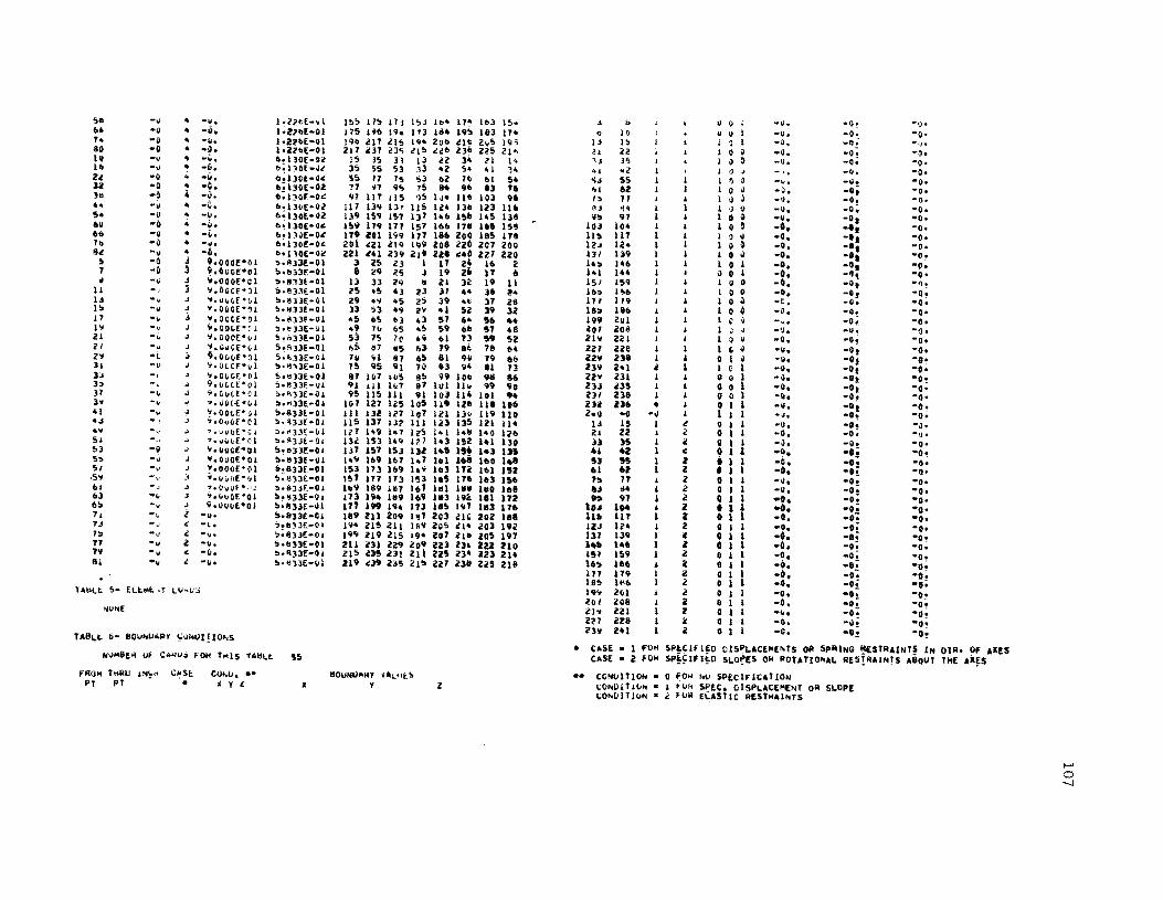
5_ -~ .. -~. 1·l?l~E-.I 1~' 1I!t 171 I !:d lb- 11- Ib3 I~* ~ b I) V , -v. -0 ·0' 104 -~ .. -0. 1.2;ob[-01 175 HII 19. 173 a4 19~ 163 IH " 10 11 U I -u. -0 -g. h -U • -II. I'UI>E-QI ! 9b oi!17 lIS I". ZOb cl~ 2\iS 19i I'; I" I 0 I -~. -Q -I) • 80 -0 • . ~. 1'2<'1>[-01 217 eJ7 23<; lIS e21> l3b US 21~ ~1 U I 0 g .~. -0 ·0-IV -" .. -ii, 1>!130E-Oc IS J!. JI 13 II 34 itl 14 " J"l I 0 ~ -II. -0 ·0· III -" .. -~ . bol30E-U 3, 55 53 1) -2 5. 01 H 41 ~2 I 0 .; . " -II. -0· 2<l -0 -II. 0!13QI.-O« 55 17 IS 53 I>Z 71> 1>1 54 'io$ 5S I ~ ~ -iJ. -~. -0. U -0 • -0. 6! 130[-02 71 H 9<; 75 u 96 8l f6 ~I 62 I 0 II -J. -0; -0. lit . ~ 4 -~ . fI.l~g[-O': 97 117 115 ?!t 1 ~ .. 111> 103 96 I, 11 I U l -u. -4. -~. h -u • -G. b!13vE-OZ 117 13Cl 137 115 I c4 llb IZ3 116 ~J i4 I :l Q -u. -0; -0. 5- -II - -Ii. I>~ 130[-OZ 139 1~9 157 137 hlo Hob 145 138 IIl1 97 1 0 il -ij • -0; -0. 6U -0 .. -il. b~ 130[-0" 159 179 177 157 II>" 171 161 15~ 10l 10. I 0 ~ -6. .'. -0. 60 -~ • -~. "~IH[-oe IT9 ifOl 199 177 186 200 185 lU 1111 117 I ~ 01 -0. -'1 -0. 7b -0 .. -.. b·130[-0' 20i ~ZI ljCl 199 201 c20 207 cOO 1t'~ 12. I 0 ~ -0. -as -0. Bo! -II .. -6. "!110[-4c 221 241 Z39 ZI' UI ".0 ZZ7 220 131 139 I 0 II -0. -0, -0. ir. -0 j •• 000l'OI ",.llllE-Oi 3 Z5 Z3 I 17 Z4 16 2 lu 1410 1 0 i -0, -Ot -0. 7 -~ 3 9.h~E·01 ~;bl3[-01 i 29 '1'> J 19 26 IT 6 hi 144 iI 9 I -0_ -9! -0' ~ -Ii 0$ .... Ooopel "1113£-01 II 33 2Q II ZI 3i! 19 II 151 159 I " 0 -0. -Ot -~.
II --.' '3 ".bOGf-ll '.1!33(-01 <'5 45 43 23 J1 4" 36 "'. 11o~ I'!>b I 0 0 -0_ -~f -0; I, -v ~ o;.uCJ(,[·iJl ~·~JlE-61 Z9 ." 45 z; 39 .t; 31 .26 171 1'9 I 0 Il -t. -Q. -0. III -" ~ ".O~Of·H !t!H)3E-OI 13 ,3 4'11 2" -I 5Z 39 3l Ih lItb I 1 0 b -0. -4. -0' 17 -. , ".OOH·DI ;.d)3E-QI .. 5 oS U 43 57 6" !l6 .4 199 2ul I I 0 Il -.. -0; -0. 1" -0 ~.COH- [I ~·n3[-UI .. 9 71> 65 .!> 59 611 !ll 48 lOI 2011 I 1 1 • -~. -0; -~. ZI -. ~ ~.OOOE·ill !'.o33E-OI 5) 7S 70 4" 01 13 S9 52 21'1 221 I I I ~ \I -0. -0- -0. cl ·v ~.u"'OE·\ii S;R33f-01 toS 117 liS 63 T9 It 78 64 <Ill ue I 1 1 0 0 -Q. -oi -0. Z" -~ ~ 9. ~O~E":l1 5 •• 33£-01 711 YI 87 65 81 9ij 79 68 iz ... 23. I I 0 \ " -ij, -9a -.~ 11 -0 .; ".~~CE·\i1 5'~'\3f-01 75 95 9\ 70 8l 94 It 13 Z3'i iI·l l 1 I C 1 -II. -Ot -e· 3~ ".CIiC(·~1 5.~)3E-OI 8f 1\)7 I~S e!t 99 lOti 'Iii .6 2Z" 231 I I 0 4 1 -0, -oJ ·o! 3" 9.v~lt'cl ~.833f.-ul 91 HI IH 87 11/1 lilt 99 9D 23J i/35 I 1 0 0 1 -0, -Ot -0' l1 -. .; ".Cvlf·01 ~'~llE-OI 95 US 111 91 IOJ 114 101 9. Z)I Zl8 I I 0 0 I -g- -0. -0' 3" -, -! --.velc·E·Cd ","13£-01 107 \27 Us 105 119 Ilfl HI ID6 2)0/ in6 • I 0 I 1 -v. -oi -o! 41 -. .; !.QOt"E·lj! '.833E-01 III IlZ 127 107 IZI Ill> 119 110 l.1I -0 ·01 I 1 I I -J. -0. -0. "J -': .> ".ovllE'CI lr. ~)3f-O' 115 137 13;> 111 123 13~ 121 114 I' U 1 l 0 I I -0. -.; -J. ." ·v "'.vv(.o(·c;: ~"'3J~-OI 117 149 1_1 Iz!> 1"1 I .. e 1"0 I~b Z. 22 C II 1 I -0. -0; -Ue 51 -" '16 ""fI ... [*Ql ::"A))~_Q, 13,a IS3 14" 1?1 1.3 ISZ 1.1 13. II :IS l II I I -h -O~ -0-53 -" ~ ~.ijQ~f·OI !hd33l-01 137 157 15J 132 1,,11 IS' 141 I» .1 .2 C 0 I 1 .~. -.! -O~ 5::. -u .; ".OUOE·OI 1o·~13£-QI I .... 169 167 1_7 le.I 168 IflO 1._ !U 55 if • 1 1 -c, -0_ -0-S/ -v J :;.OOOE·OI 1O!831E-0I 153 173 1119 .... Ib3 In 161 152 61 ., l • I 1 -0. .,; -0' .5" -, 3 .... ,l'IoIO[·Ql ~.>!)3E-OI 1st 117 173 I~l 165 176 163 IS6 "lo 17 i l 0 I I -~. -0; -0' 101 -, J ~.()\,jUf *,iJ ~.633F.-O. III'" 189 In 16' 1111 III 1.-. 168 -" 1:14 1 Z 0 I 1 -U. -0; -0. u ~" :J ",v"OE'OI !I~1I33E-01 173 194 1119 169 11t3 I lie: III 17' '" 91 1 Z 0 I 1 100. -0; ·0-6!o -", .; 9.QUIlf.·01 !o'1l3J£-~1 IT? 1" 194 III 185 197 1113 176 'U '" • i • I 1 "0. -oi -o-n -" l -y. !o.II33£-Gl 189 211 209 1~7 l03 c" 202 18. llll liT I Z • I 1 -0. -0. ·0. 70$ -J C -l.'. ,,!b,Jt:-O' I"''' 215211 Ifi9 ZgS CI· 20) 19i IZo$ Iii." I Z Q I ·0. -0; -0. 7!:> -- " -II' ,.833£:-01 19 .... ll9 215 19- Z07 II" lOS 1117 131 139 1 2 • I -.- -0; -O~ 77 -II Z -II. !j·~33£-0I 211 e31 .2Z9 209 ill U~ ZZ2 '10 1'- 166 I 2 • I .11. -0; -0. 711 -", " -il. ";"33E-0I ZIS <l3!1 211 Zit Zl'5 Z34 i!2:3 214 lS1 1~9 I l 0 I -0_ -0; ·0. BI -II i -~. !o'''J3E-ul 219 .:.)9 Z~5 21!> ZZ1 zn ZZ' 218 16!> 166 i 0 1 -0. -0; ·O!
111 179 Z 0 1 -0. -0-= eO! 185 11'11 2 0 I -0- -0; .,.
TAi;l.t S- fl.l:.141:. .r lU ... V;;i 19'0 llli Z 0 1 -0. -oi ·O!' 201 i/08 2: 0 I -0. -0. ·O,! /juNE cl" ZZI 2 0 1 -h -0; ·O! iI'21 Zl8 I: 0 I -0. eO! ·O! l311 Z41 2 0 I -0. -O.! ·O! TABLI:. 6- 80UhUAP' ~",.1.11 ! 10"1$
• CASE • I FO" ~P~Clfl~O 01$PLAC£M[~TS OR 5PAING ~ESTRAINT! IN 0111 • 0, AXU NUHSEil Of C"~IJ" FOf< Trlls TAIII.I:. '55 CASE • 2 fO" SP~~I'I~O 5LO~ES ON POTATIO~AL RE$!AAINTS A80UT THE AX~S fRO,", T"AU i"'~'~ c~se COt.iU. •• 1I0UNI.1"M' ~"~tJl!> •• CONlilTIOh • 0 FO" ~v iPECIFIC"TI0N
PT PT ~ Y t. • Y Z 1:0 .. 1>1 T lli~ • I ~uk SPEC. OISPLAC[HE"IT 01'1 SLOPE \,;OhOIT luN a 2 fOM ELASTIC RESTHAlhTS

APPLIED LDAOlk~S
CDkC[N!RAIEu tuwCE~ 0. ~~~(~T~ • r,LD~AL COORU!NAttS
LOAD Clost;
hU~9[R Uf tAR~S r~ THIS TABLE 6
FFIOM T~U 1l'lC:R P! PT
111 -0 -u 183 -0 -(. 185 -0 -0 18, -0 -~ I'. -" -II 199 -Q -u
I 1 • ylS
FURCES IN DIHECTIONS ,: , -U. -0. -~. -0. -0. -0. -0. -0. -!I. -0. -II. -0.
o MO~[N!S A80UT 10.[5
1I Y
2.560[003 -0. -0. 5.520[003 -0; -0. 3.350['0:' -0; -Ot 8.!lOO~002 -o! ·0. 1.840£003 -I). -g. 1.120t·03 -9; ·o!
-0. -0. -0. -0. -0. -0.

I 171 179 4 3.125E·00 1>,0]7£'01 0, 1.71>2['01 6.037£'01 O. PAOSII", SH!LL 6 • MAST[II OECK • ABO!lRAOU', .. ATlOCK R[VIStO~ OAT[ I> ~AY 1971 189 199 5 3,125E.00 6,837£.01 3,030E.00 1.11>2£.01 I>.~n£.ol '.O'Or·O~
SM[LL 6 REPOII' COO[D av AaO[lRAOU' WOV[""[II 'I, 1911 I'll 201 5 '.I2SEoOO 6,837[001 00 1.71>2E.OI 1>.817!001 0, 3 • SPAN CONTIWUOUS HIGM~AV "AIOI[, .. 520 TIIUCK lOADINGS ILI.,.T U'lITS, 211 219 4 3,125EoOO 7.'87 t,01 "O'~t!:,OO 1.762[001 1,387[.01 3.030[.00
2iJ 221 4 ',IZ5hOO 7.'87[,01 n. 1.762E,01 7.'~7['0l O. 231 239 4 3,12UoOO 7,938[.01 ',030[00n 1.11>2[,01 T.9~8!'01 '.030[00n 23J 241 4 3,I25EoOO 7. 9J1[.0 I O. 1.11>2['01 7.9'U,01 O.
PROII 6 II 5 flo 7S0E.00 O. 3.0]0['00 1.400[.01 O. 3.no[·0~ 303·A SV .... ETRV ABOUT TH[ h .. NSV[IIS[ AXIS .. NO .. NTISv .... ETRV LONGITUOIW'llY 7 12 5 6.750E'00 O. 1.51~[.0~ 1.400E.01 O. 1.515['0"
'" 14 5 3.125[,00 00 1.51 '!i[.on 1.71>2['01 O. 1.515,,·on TABL[ 1- GEN[RAl PQOIl[M l~fOR"ATION 68 73 5 6,750E'00 2,438£'01 3.01n[.00 1.400['01 2.4]8[.01 3,030f"On
1>9 74 5 1>,750£.00 2,4'8[ ,0 I 1.51'5[,0" 1,400[,01 2,438£.01 1.515[,0~ HUM Of' !LEM[HTS I! 66 76 5 3,115['00 2.4]8[.01 1.51'1£' 0" 1.762E.01 Z .4]8[.0 I I.U5['00 HUM 0' poINTS 241 130 1315 !I 1>.150[.00 4.1>17£.01 3.03n£.0~ 1.400[.01 4,637[.01 3,030,..00 HUM Of' LOAO CASES I III 131> 5 6,7'50[,00 4,6"£001 1.515£'00 1,400['01 4.637[.01 1.5l'S['00 ELEMENT ,OIlCES R[QUIIIED I I • Y[I I 1 III 138 '5 30125E'00 4.637r· 01 1,515£'00 1,762[.01 4.637[,01 1,515[.on
n2 19" 5 1>.750E'00 1>.811£.01 '.03n".0" 1.400E.01 6.117£,01 3,030['00 193 19~ 5 1>,750E.00 6 0837£.01 1.51-;(. n~ 1. 400[001 I>,~ H[,OI 1,5Ur oO O
TABL[ Z. MA1[RI"L [LASTIC PROPERTI[I 198 2041 I 30125E oOO 6,137[001 10515[00~ 1.71>2E oOI 6.837E oOI 1.515[·0~
HUMBER 0' C .. ROS fall T .. IS Hal[ 4 fAIL[
4 _ EL["["T PHOP[R11[S
MAT II Of RECTI ON V l'Ill!ECTlOW 5HUI! NOOULUS TVP[ [I[ VllY [V v'tX 6 WUN"[II o~ C.RDS fOR 1,,[S HAL£ ~1
1 4,llO[0'9 3.000[-01 i 0900E'09 l,n.I_OI· l,I1!l[oOt. ""001 'M"U I~C" .. u "",GlE r~[C"N[~S ELf~£~r NnO['l It 4.3Z0E oOI 1,500[-0 I 4,3;00(001· 1.500[-oi· 1.81I1~'ol. EL .. T EL .. T HO£ 3 4,3ZoE ooe I.SOO[-Ol 1.640£0'" 3,OOOE_Ole 6.1'57f',Oh • 4.320Eo09 3.000[-01 2.6'i0(.~1 1"40[_~'O 1,-U"'Olo I -0 -0. 4.2'lOE-ft2 • 7 6
2 ·0 -0. 4.Z'IOE-Ol 1 • I 6 o I A5SU .. ED VALUES 3 -0 -0. 4,Z'i0£_~2 • II 11 8
• • 0 _0 • 4.250[_0;> 11 \4 13 II U • 0 .0 • 5,210[_Ol 66 69 loS 65
TAIL[ ,_ NOOAL POINT COOROI"&T[S 24 .0 -0. 5.210[-01 1>9 71 10 6!l Z!I .0 .0, 5,210E_01 11 14 13 70
NUMIj[1I 0' C .. ROS FOR T"I$ TABL£ 4i 26 -0 -0, 50110[_ft2 h 76 1'5 73 45 .0 -0, 50lUE_or I2S UI nO I2T
'11001 THIIU IMCI! STARTING POINT COOIIOtMAT!!,S ENO PorN' CMROllIIUlS 41> _0 -0. 5.210E·02 III IJ] 132 13ft PT PT II Z J. y Z 4" .0 -0. 5.210[-02 133 U6 135 132
4' _0 -0. 5.210[_01 136 UI U., 1J5 1 ·0 -0 o. 0, '1,030£'00 -0, -0, -0, 67 _0 _0. 5.210£.02 190 193 192 189 n 6J 20 0, 1,125[,00 3,030[,00 O. 2.431[,01 3.030('00 .. • 0 -0 • 5.210[-02 Iq3 195 19- 19;0
IS 18 10 0, 3.111[.01 3.030[,00 0, 4,U7[.01 3.030[000 69 -0 -0. !>.21O[_02 I 'I!> 1911 lilT 194 14'1 111 20 0, 5. 231£001 3.030[,00 0, 6.811'1[001 3.030['00 70 _0 -0 0 !>.210[_~2 1118 200 199 19'1 109 U9 20 0, 1.31'1[.01 ',030[000 0, 1,911[,01 3.030[000 6 _0 4 .00 1.2"6[_~1 5 i!7 l.'!I :I II 26 IT 4
3 1, 5 3.125£.00 O. 3.030[000 1.162[,01 0, 3,OJOr'00 II .0 4 .o~ 1,IZ6£_ft l Zl 41 4!1 Z!I 31 41> ,., ll> 5 15 5 3.125[000 O. ~, 1.76l £,01 00 0, 11 .0 4 _0. I.Z:!6[_01 47 61 65 45 58 .. 51 46
25 3' 4 3,125[,00 1.125[,00 '.030[>00 10 762£,01 1 0125£,00 3.030r'00 ZI _0 4 .0, 1,2'-6[_01 1>7 89 17 I>!I 10 III 19 66 11 35 4 301l5[.00 1,115[,00 0, 1,762[,01 l,a!l[Ooo 0, J4 .0 4 ~Oo 1.21.'6[.01 n 109 lOT If 100 loe 99 III 4! 51 4 3.125£.00 1,6ZS[oU 3.030[.O~ I, "1>2E,01 1,I>;o!l[.01 3.030[000 40 ~O 4 _0. 1.2!6[.01 10. 129 127 101 120 lie 119 101 47 55 4 3,125£,00 1,"2n,01 ~, 1,1"2[,01 1.6!i!1£001 0, 50 .0 4 -0. 1,2;>6E_ol 12'1 151 149 121 14, 150 hi 1!.'1 $!I 75 !'. 3,U5E'00 2,43"[,01 3.030f oOO 1.162[001 2,43!1[001 3,030['00 56 -0 4 -0. l.l?6[-"1 151 111 169 14' 162 170 hi 150 67 n 5 3,IlSE'00 2,4"[001 0, 1.762['01 2.4,,[001 0, 1>2 _0 4 -0. 1.2;>1>[_01 171 191 189 169 181 190 181 hO IT 95 4 3,IZS[oOO 3,171[001 3.030£000 1.1,,2[,01 3.lTU:oU 3,030[000 12 .0 4 ·0, 1,l!6[.oi 191 2)) !II 119 204 1I2 2ft] 190 19 9., 4 3,U5E.00 3,I71E,01 O. 1,762(001 3.171[,01 0, 71 -0 4 -0, 1.2:!6[_nl 213 2n 231 ll1 1'l4 231 lU 212
101 115 4 3,125£000 l,904[,01 3.OJ~['0!) 1.762E.01 3.II~41':001 3,03 0t'00 8 _0 4 -0, I;U6[_OI 10 1I 1'9 8 20 30 19 9 109 11" 4 3,125£ .00 3,'04[.01 o. 1.762['01 3 •• 04[.01 0, 14 -0 4 -0, hZ!6[-Ol 31 'I .. 19 40 50 ,._ 3D 121 13'1 5 :tt 125E,00 4.637[001 1,010[000 1. 762['01 4,6]7['01 3,OlO~ooa 20 _0 • _0, I!ZZU_OI 51 12 10 4, 60 n 59 SO 129 U9 5 :t.I2U·OO 401>37[.01 0, 1.71>2['01 4.617[001 0, 30 .0 • _0. I !ZI!'6[.0I 12 9J 91 TO If 92 III 11 In 15., 4 3,125£000 5.231£'01 3,0]0('00 I. 762[ '01 5.2]1[001 3,030['00 ,. -0 4 -0. 1,2!6[-01 9J 113 111 'II 102 liZ 1ft I 92 151 159 4 3,125E'00 5,237[001 0, 1.762£'01 'S.l"'oOI O. >2 -0 4 -0, 1!2U[-ftl 113 13. 132 III 122 In III liZ 169 111 4 3,I2SE' 00 1>,037['01 3.030,,00" 1,762[001 6,037£001 3. 030,-00 52 -0 > -0. hUU-OI \l4 155 In 1!2 144 154 141 In

...... 51 ·0 4 ·0. 1.1'16[-01 155 175 In 15, 164 11. I'" 154 J 5 1 1 -0. -0. -0. ...... 6. .0 Co .0. 1!2Z6[-U I1S Ut. 194 In 1&4 195 I III 174 & 10 1 1 0 0 -0. -0. -0. 0 1. .0 4 .0. I,U6[-~1 196 217 215 IV. '106 Z16 20S 195 lU 144 1 I 0 0 -0. -0 • -0. 80 .0 4 . 0. I.Z26[-~1 t17 237 US t15 U6 236 l25 21 6 13 "13 20 I 0 0 -0. -0. -0. U .0 4 .0, 6.1'0[.01 15 35 U u n ,4 21 14 15 115 20 I 0 0 -0. -0. -0. 16 _0 • .. 0; 6,130[·111 3!1 loS 53 33 U 54 41 34 )]1 17' 20 1 0 0 -0. -0. -0. U .0 • .0. 6.130[.02 !I!I 17 75 53 61 T6 61 54 199 l" ZO I 0 0 -0. -0. -0. 312 .0 4 .0. 6;110[.0' T1 91 'IS '!I 114 96 e3 76 15 '55 lO I 0 0 -0. -0. -0. U .0 4 .0. 6.!!0[.01 'I' II? 11!1 9!1 104 116 1~3 96 11 117 10 I 0 0 .0. -0. -0. •• .0 4 .0. 6.110[.01 117 139 In II!I 124 138 In 116 139 179 20 1 0 0 -0. -0. -0. !l4 .0 4 .0. 6; 110[.01 13. 159 157 131 146 1511 145 138 201 2,.1 20 I 0 0 -0. -0. -0. ",0 .0 • .0. •• !!,[.Ol 11. 179 1T1 151 166 118 I"'!I 1 !III 21 61 lO 1 0 0 -0. -0. -0. .. .0 • _0. 6!1l0[.02 119 101 199 I" 1116 200 liS 1111 U IU lO I 0 0 -0. ·0. -0. 16 -0 • _0. 6.!!,[_02 201 211 II' 1'9 lOll 220 lOT 200 145 lOIS 20 I 0 0 -0· -0. ·0. "I .0 4 .0; •• 130[.02 1'1 141 139 219 l211 240 lZ1 21/0 l07 2Z1 20 I 0 0 -0' -0. ·0,
!I .0 J 9.000['01 5.1113[.01 ) 15 l!3 I n 24 16 I Z2 foZ 20 I 0 0 -0. -0. -0. 7 .0 J 9.000E·nl !I.133[_01 II Z9 n , 19 21 IT 6 84 \24 20 I 0 0 -0· ·0. -0. 9 .0 3 '.000['01 !I.II'U[-OI 13 33 n II 21 32 19 11 146 \86 20 1 0 0 -D. -D. -0. n • 0 3 9,OOOE'01 5.II:U[.01 25 45 U U 31 44 36 ,4 '01 l .. - ZO 1 0 a -0. -0 • -0.
13 .0 .1 9,000['01 1,IIU[.OI 19 49 4!1 25 ,. 411 " ZI 14 !l4 10 I 1 0 -0. -0. -0. U .0 3 9.000('01 5.8ll[_01 n I) .. 19 41 51 39 32 '6 116 20 I I 0 -0, -0, -0. 11 .0 ] 'I, OOOE'O I l!n3[_OI 4!1 6!1 63 43 51 64 !l6 44 Ile 178 lO I "I 0 -0. -0. -0. 19 .0 ) 9,000[401 5.1133[-01 49 70 6!1 45 ,. 6- 57 4_ lOO , ... O lO I I 0 -D. -0, -0. II -0 3 9.000['01 5~I'3[_0I !l3 15 ,0 4'1 61 73 59 52 239 Ul 2 I 0 I -0. -0, -0. n .0 J 9.000E·01 !I.U3[-01 6!1 117 85 63 " .. 71 6' U9 U- I I 0 I ·0. -0. -0. n -0 ) 9.000[001 5.133[.01 10 'It .17 65 III .0 7' • 1 240 -0 ·0 I I I -0 • -0. -0, ." .0 3 •• OOOEoOI 5.IHr_OI 75 'I' 'II 70 II 94 ~I 13 229 241 I iI I 0 _0. -0, -0. n .0 3 9.000E·Oj 5.813[_0' 87 107 105 I!I '19 lOb ~8 lib )!I _0 J 9,OOOE'O' !I.IH[.OI 'II III 101 IT 101 110 99 .0 CASE • I 1'0" SPECifiED DISPLAe(wENT~ o~ SP"YNO "ESTRAINTS IN OIR, 01' AI[S 11 -0 3 9,000('01 5.IIU[_ft\ 9!1 115 III 91 103 114 I~I 94 eASl • Z "OR SP£CI'IED SlOPES 0" ROT.Tl~N.l R[STRAINTS .~ouT hiE AI[S !9 .0 3 9.000['01 5;1113[.01 10' 121 Il!l 105 119 126 1111 106 41 .0 3 9,000['01 5.813E_OI III 132 117 107 121 130 119 110 •• co"onlo" • 0 "OR NO SP[CI"ICATION ., _0 .1 •• OOOE·01 !I.IH[_OI II' 137 13l 111 113 135 UI 114 CO"OlT[ON • 1 ~OR SPEC. oISPLACE"["T ~R SL"P[ 4' .0 3 9,OOO[ .01 5,133[_01 127 149 I.' 125 141 \48 140 11'6 CONDI TID ... 2 "OR ELASTIC REsr"AINTS 51 .0 J 9.000['01 !I.I"!.OI III 1'J3 1.9 127 143 ISZ 141 130 !l3 .0 3 9,000[,01 S,lnr.OI 137 15' 153 III 145 156 141 IlS !II .0 3 9.000[001 5!UU_OI 149 169 16' 147 161 168 160 h_ 51 _0 3 9, 000['0 I 5.lu[_nl 153 1'3 169 149 163 I7Z I~I l'5 l APPLIEO LOAOIN.5 59 .0 3 9.000!'01 !I.83J[-0I 157 177 173 IS] 165 176 1.3 1!l6 &1 .0 3 9.000!·01 5,n3!_~1 169 119 181 167 III In 1~0 161 eONC[N7IU T(O "DReES OR "O~ENTS - ~lO~Al cnORDINAT[S 63 ·0 3 9,000['01 5,ln[_01 173 194 189 169 113 192 1~1 172 6!1 -0 J 9,OOOE'01 5,I:U[_01 11, 199 194 173 I~~ 19' 1"3 176 ,I -0 Z .. 0. 5,1I1U_0\ 119 211 l09 181 ?O3 210 Z·2 1111 LOAD CASE 1) .0 2 -0. ,.U3[-OI 194 liS 211 189 l05 214 2e3 192 15 .0 l -0. 5.lu!.nl 199 219 215 194 20' 211 lOS 191 NUMII[II 0' CARDS fOil 11415 TAelF I 71 .0 2 -0. !I,IUt-Ol Z11 l31 Z~, 109 III 230 In ItO 79 -0 I -0, 50n'[_~1 215 235 231 ~II ~25 234 223 214 EL[M[NT lOADS TO I[ AOD[O I 1 • YES I 111 .0 2 _0. !loI13[_01 119 Z3. I'S 21S 22' 231 iZS 2111
FRON ?"Ru INCR 'ORCn IN OIAtCTJOIII!I MOIolENT! 'lOUT U[S
lOT 107 x v 7 X v l TABLE !I- [1.!"t",T If')AOS
181 -~ -0 -0, -0. ·4.2':'1[·0' ·0. .0, -0. NON! In -0 -0 -0. -0. -'§.9t"E·Ol -0. -0. ·0.
189 -0 -0 -0. _0. "1.4tO[>" -0, .0. .0. 194 -0 -0 -0. _0. -l,98"E'03 -0. _0, -0.
TABl[ 6- BOUNDARV CONDITIONS 131 -0 -C -0. _0. -1.6'10[003 .0_ _0_ -0, n. -~ _0 _0. _0. .1.140!.03 • 0. .0 • -0, NUM,,[R 0' CARDS '011 THIs tABL[ '" US -~ -0 _0. -0. "4.14~t·O' .0_ _0. -0.
nl -0 -0 _0. _0. -1.400[.0' .0, .0. -0, 'ROM THIIU I NCR CU[ CO .. O. •• IIlIu .. nAIIV VALU~S
101 101 • I v Z 7

'PR06"A" SHELL 0 ~ MASTER DEC~ - AHOELRAOUF_ M'!LOC~ REVISiON DATE 6 "'r 1971 SHELL 6 HEPORt COO[O 8' .BOELPAOoF NOVE~aER 9_ 1971 l - SPAll-CONTINUOUS HIGH"AY RRIOGE+ "520 TR~C~ Lo'~l~ijS tLH-FT ~NITSI
TA&Lt 1- GENEwAL P~OHLEM lNFO~MATJON
NUM OF ELE"""lS NU" OF POI"H;-NUM OF LO.O'CASES ELE!4t.NT FORCES R~'JUIR;O I 1 • fES
T.~t 2~ "AI~HIAL ~LASIIC PMOPERTl~S
NU"B!R Of ~~R~S fO~ T"IS TA~E 4
MAT A ""~~CHON TYPE tA V"
62 241
1 1
V OIRE"1I0N EY . - ~yx
I II. j 4
4.J~:)£.JIi
<t • .jcOE.vtl 4:JcOE--jlj ... Jt'\lf. ... --
..$ ... 00[-01 1.'wOE-OI 1'''QO!~OI 3.U"CE-OI
1.9011£0"9 40320E-O ... !h6'hIEo07 Z+6S11E-OI\
1,319£-111-l;~OO[-'t-3.000r .. oz-1.1140(-0",-
10 11IE-0" 10811£_0. 6.157£-01. 2.-13£+08-
TAilLt. 3- NO"AL .. (jl"~ Co\H!Uj>,'!ES
NIIMBERJf C~"<.IS FOil. I"'IS TAil.... 41
FHO" TMRu I"fC'< PT PT
~!'MTING POINT CVO~UTNAT~S
I -0 23 t>l II! lZS
141 187 209 229
J 13 5 IS
25 :U iI1 35 "5 53 47 5!> 65 15 67 77 1:17 II!> 89 91
107 115 109 117 127 117 129 139 149 157 151 159 169 ITT
A Z
-Q fl. iU "'_ 2i! ... i!(; u. 2u .(1.
!J J •• tI.=E+OO !> J •• 2SEoh • 3.lllE-·OO • ..$.1':;[',)1/ .. j • .l'::~L·",O
J.l~;EoOO !> J.I~~E·~O ~ J".:"lo~o - .;.I':~£·~O .. J ... ,t!)L·Iijt)
• 3"~~E·OO • 3.1i!;£·OO 5. J.u::~E.vO !> J.I<'S£+UO • JoIc!>E-()O .. ':'.l~:t ... ·~O 4 J.l~5Eoilo
\I. t>. 'Z5E '1101 3,17IE'vl 5.2) 'Eo~l 7 .JA 1['411 O. U. 8.1l,E+JO 1I.12,E·\l0 1+025E'\I1 1.';>5E·01 2. 4 36£'111 2.-3I1t oOl 3.I71E-"1 3.171[',,1. 3.II04!·"1 3.'10~E-u1 _.o3/EoJI _.6)1E·~1 S.~J IE'Ol 5.i3 1E·"1 6+ n7E'~1
3.030E.OO 3.03u"·00 ).O,"E·O~ J.C3DE+~~ ",O'O~·\lu 3. ti3~£'''~ ~.
J+Ol~E'OQ O. 3.030£+"u O. a.030E'UII ~.
3.03,E-.,u Q. 1.030£·uJ ') . 3.iJ]uf:.U;w O. 3.no[,ou O. 3.03I1E·00
~NU -ol~' COOR~I~.T£5
-0. O! o. ~! 1/. 1;1Uf.·1I1 1:762Eo OI 1.7611:'01 li16lEoOI 10 1;'21:.*01 I!" 1621*'1 1.761t·01 1;762E+01 1:16lE'01 1!76lt'01 1.162E·01 1:.76lE·01 10 16l!l'ul 1;,62E·,,1 I: 16U-OI .~7l1Zt·UI 1!7!JU'H
, Z
-0. 2+438E-.l 4,637£'01 ~.!l37to.1 10931E- III c. O' A.lisE·oo '''125EooO 1·6~5E-Ol l,lIZ5£'01 2.4lt>f-Ol ", •• 3t>t-1I1 3.171E·ul '.lllt·ul 3·1I04E oul }.9.4E'UI 4.,,37E.ul _.637E+~1 ~.zj7£·Ul !h237t-"1 6'oJ7E~.1
-0. ).030£ .0. ].030f-OO 1.030[·n. 3.030[-"].03I1E-vu O. ]_OJOr·till ~+
1.030[·Ou O. 3.03OE·'1 o. l.o30r·ou J. 3.030£''', a. ).030E·0" O. '.O}O(.~J
O. 1.0]Or·vu
171 119 199 1~9 .91 ,iloll 211 ~19 213 UI l31 e39 233 241
II 11 7 1Z 4 14
69 73 69 74 66 76
lJO 135 131 U6 128 138 192 197 193 !98 1'10 ~"O
~ J,125E+JO ~ 3.1<,t+.O ~ J.lc~L+':'O
.j •• "!)£·~O 4 J.I~S~.OQ ,. 3,1~5E·"O 4 l.I'!oE.~O 5 6.1!>UE'OO 5 6.1'iiEoOO 5 3 •• <5t.;,0 S fh f;'""f. .vo !:) ch1i;)vt.+vQ !> 3 • .lca,,+OQ b fI).I;)JE.~O 51 b.tZ>It,..c,O !> ,J..,h .. oi!o 5 1I~75~E.OO !o ., h.E+~O 5 3.1l~E'~0
b.~37E'J1 ~.tiHE+"l b.8J7~·Jl 7.3A7~·ul 7.Js1f.·ul 7.~38f.o"1 7.~3t>E-~1 O. o. O. 2. 4 38E+"l 2 .... ]oE·,,1 2._36E'ill 4.'3n.,,1 4.1131[+.1 4.4I)1E+JI 6.83 lE •• 1 f).031E·ul 6.tt31E·":1
O. 1.~30f..O~ o • 3.0)OE.uu ~.
]. 030[ .. " n. 3.030E+f/ij 1.51SE.OI! 1.515E+UU 1.~30E+-.IU 1.SlSt,.,HI } .'ilSE+vu J.G3Qf?+Qu: 1.S1:;t. .. ,,, 1.5H.E+I/U ~.030Eoh
1.51 !tE·,," 1 • .,15E·C.
TABLE 4 - ELE .... '.T ':'~UI'E"TlE5
NUMijEK ~f CAw~j fO~ T~IS TA~LE ~l
F80" T"RU lN~H ~Al fL"1 ELMT lY':'E
-. -v -"
-"
-. -u
-" ·u -v
, 4
-.. -". -.. -6.
-u. -~.
-~.
-(.. -~. -~. -v. -Ii. -~. -6. -".
-.. -to
... l..;.,rf .. vl 4·2<;at-OZ "·2SH-OZ 4.2561';-02 !>'<!\OE-ul 5.c\vE-Ol 5·210E-Ol '.210E-OZ ~.2!uE-Ol !o.ZI~F-Oi 5.210E-0)2 S.cl~E-uc ,.210£-02 S,cl OE-O~ ~;~'IIE·Ol !>.~ICE-Cc !.2?,,£-Cl l.c2C>E-ul I.Z?(,£-Ol I.Z1'6E-O. lol1'6£-~1 1.2",41[-01 1.C26£-O. 1.""IIE-OI 1.Z?"f-H 1.zzOE-n 1;226£-01 1'2""£-111 l·iZ,,[-ul l'~2"E-0l l·ncE-Ol I 2211£·01 ! ncE-Ol I 2~"E-OI
1.762[+01 I; 702E+ 0 1 1:762~·UI 1.7t>2E+UI 1;:762E+Ol 10762E+OI 1:162E'01 I ;"~0f.'01 1;400E+OI 1:762£'01 1;"OO£-QI 1.,,<';Qt.+Ol 1:102"'01 1;4UOt.·~1 1: .. OOt.·Ol 1 ;76Zt·.1l 1;400l'Ol l:"UOE'Ul 1~7oZ~'Ol
.. 1 1 9 9 12
Ii! 14 ~II ,,9 .,w 71 71 74 74 76
1211 131 III 113 133 136 13;' 131 1 ~O 193 193 195 IllS !91 19& lGU
S 21 21 ~7 41 67 67 89 ,,9 109
109 129 129 151 lSI HI 111 I'll 1111 e13 ell i33
IU 31 31 !>I 51 72 12 9l 93 113
11:> 134 134 15!i
(I,.037E.\ll ".837E.l/l ~+8l7E·ul 7.387£·01 7.3117E·1/1 7.9l&£·l/l 7.938E·ul O. O. O. 7.ItJdt::+vl ?4JaE-H C'.4JtlE·ul ~.,,37E·l/l 4.,,31E·ul hbJ7E'1I1 6+837£'\11 b.bJ1t:·Ol "'.831E·,,1
O. 3.030E·OU O. 3.0JOE·." II. 1.OlOE-00 O. '.030E+OI/ 1.!iI!iEo), 1.515E·eo J.030£'o-1.!>15E+Uv 1.515E·)u 3.030E-0II 1.515E+0 .. I.SI5E·0~ 3.030E·O~ 1.515[+0(' 1,515E+U\I
18 26 11 38 46 37 511 66 57 10 88 79
1110 1.00 99
4 26 46 66 88
120 iiI II' 142 1511 h1 Uti! 17~ 11>1 ll1i! l'IiI 181 2u- lie 203 U4 i!3~ 2lJ
ZO 30 19 40 !ill 19 60 71 !>9 81 'ii 81
10i! 11';' 101 122 13~ 121 144 l!i- h3
1011 128 1!t0 170 1110 212
9 30 50 71 9Z
112 IJl

,...... 5. -u • -~. 1o(7o£-GI I~~ J7!> ,7) IO;J I.· 170 I~J I !>4 ) U - J. -~! -0'
,...... N 6. -" • -tJ. I !2zcE-OI 1/5 19b I~. 17J I •• I\I~ 103 17" 0 I', ij V -.. -0. -n.
10 -" • -9' I !2;>I>E-0I 1"11 ~17 <I~ i c." c",b llo ~,,~ 1~5 141 I" v 0 • 'J. -u! -0 • 80 -" 0 -u. 1.22·E-01 ll7 (J7 l3!> c I' leO ~JO U5 ll/\ I ~ 53 c·, -0. -u. -no 10 -0 0 -Ll. 6;130(-Ol 15 J5 J3 )J l2 J' II I. 1~ I\~ .t, -J. eO! -0. I" -II • -u. f>'IJoE-~l ~5 ~5 "J JJ . ~ !> • -\ )0 131 177 C, 0 c' -, . -u. en. le -0 • -w. l"l1lcE-O~ 5!1 77 7~ 53 Ol 70 01 ~. 19~ l\1I "'" 0 -u. -0; -Q. J~ -0 ~ -c.. 6;1)~E-02 77 WT ~~ 75 80 90 8J 76 I~ ,5 C, 0 -~. -0; -0' ,. -II .. -u. 6·11lE-0" 97 117 115 '15 10· III> 10J Q~ 71 11"1 C, 0 -J. -0; -0. 0" -to 0; IlOf-Oi: 117 U" lJ7 1\ S Il' IJb III II~ IN 179 ;to v 0 • 'J. -0 • -~) . 50 -v 0 -0. o.IJOE-Ol IJ9 15<; 151 1)7 1.6 Hi_ h5 138 201 ".1 Zo II 0 -0. -O~ -0· 6U -u .. -Lf. II. 13uE-Ol 159 179 117 157 166 ITa lb!> 15~ II 61 2u 0 0 -0. -0; -0. 6t> -v • -il. 601 )vE-Ol 119 lOI 199 lJ7 166 Zoo 1115 I7A 8" 113 ZII 0 0 -0. -0; -0' 7. -II 0 -~. 6.I)OE-0~ (01 221 ~19 199 iOIl 210 l07 zoo I." 1115 III 0 0 -Q. -0; -0 • 8t -II .. -0. O!130E-Ol ~iil 2.1 ZJ9 l19 ll8 2.~ 221 no u 6l (. 0 0 -u. -0. -0' ,. -ll j 9.0COE·Ol 5!8JlE-01 3 l5 Zl i 11 l4 16 l U 62 ~O 0 0 -J. -0; -0 •
I -il .; 9.u~OE·Ol 5!83JE-.l e 19 l5 i 19 Zli IT 6 80 Il. Z. u 0 -a. -0; -0' ... -" j 1I.\iOOr·OI 5.8J3[-1I1 13 33 19 • II 3l 19 II I •• IH6 2. 0 0 -l • -0; -0'
II -u " ~.~OOf·(ll 5.833E-CI 25 ." 03 Z3 31 •• i6 2 • 200 US ~'" 0 0 -Q. -0; -0' I .. -0 ~ 9.uUO£·01 !>.d~3f.-OI 19 .9 .0; l!S 39 ob II ,8 I' 5. ;tv 1 0 -0. -0; -0· I!> -. ~ ~.O"UE.-OI S!!lJJt-ul II 53 .9 2'9 .1 5l i9 II 71> lito 2u , 0 -0. eO! "0:-11 -0 j ;;.UOOf-OI !>.831f.-OI .5 b5 bl 03 51 "0 56 OA 130 I1b 2u I 0 -;1. -0. -0' III -v • ~.OOOE-Ol ".<!)3E-~1 09 70 65 oS 59 68 57 o~ lO. l20 ~'" I 0 -0. -0; -~.
21 -v J 9.aoOE-tl 5.8)3E-81 53 75 H 0'" 61 13 59 5i 23\/ ilol 2 ° 0 -0. -0; -0. II -0 • ".uOOf·OI S;~J3E-01 b!l 11 85 U 79 86 78 60 ll" l31 0 0 -0. -0. -no l" -v .l ~.~UOE·OI 5!1I3JE-UI 10 91 eT 65 ", 90 19 68 23J l3!i ° 0 -II. -0· -0' 3l -II ~ "-'.OuI,)E·o1 5!tl33E-01 15 98 91 70 83 94 III 1'3 lJl l38 ~ ~ .~. -0; -0' 3J -u ~ ';.OuuE-UI !>'''3JE-01 81 Ul 105 AS 99 lOt> 911 86 l.u -0 -" 1 1 -Q. -u. -0' 3!> -0 ~ 9.\.I\.'oE·OI 5.A3JE-0l 91 111 Iu' 111 101 11& 99 90 l3t ll6 4 • 1 -0. -o! -0' 37 -" J 9.ouOE·III 5.IIJ3~-01 95 115 111 91 103 11. 101 9. 3" -II ~ ~.1l00t:-OI ~·~31 -01 107 III Il' loS 119 Il6 118 106 • CASE. • I FilII SPtClfl~D 0ISPLAC£MENTS OR SpRINb KtSTRAI~TS IN ui A • Of AilES O. -01 ~ ~ • .JuOE·Ol ~.1I33E-OI 111 13l lil 107 III 130 li9 110 caSE· l FIlK 5P~~lfI~O SLOPES 0" "OTATIONAL ~ES!"AINTS AI!'lUT To;( A~ES
0" -u J ".';00(·01 5.8J3E-OI II!> 117 132 III III 135 III 11· oil -v ~ "".~l.Iur·(d ~·~3JE-1l1 121 1.9 101 1~5 Id 108 1.0 126 •• I;Oo.OlT 10ft • 0 full ..0 IP[CIFICAllu" 5, -v ~ ~.~~tl(·ol ~·1I33E-OI Ilil ISl 109 127 !oj IS~ 1.1 130 LO"'uIT 11,,,, • I fuN SPEC. oISPLAC~"'E"'T ow SLUPE 5J -0 • 9.0"oE·01 5.83lE-01 IJl lIT 153 13l 145 156 ld 135 LONlUTIW. • it fUA [LASTIC REST"AINT5 5!> -II j 9'UOOE-01 5.II]]E-OI 1.9 169 167 10 7 1111 16i1 160 UII 51 -0 .. II.OOOE·OI 5.83J£-01 153 I1l 169 109 163 Hil 161 15l
·5" -", ~ ~.vuuE·OI !'o'<!33E-0i l!il 111 11) 15l 165 116 163 156 61 -~ J ".OuOE-~1 !>.833E-~1 1c.9 189 181 161 181 I lib 180 168 APPLI£O LOA~INbS 6J -c. ~ 9_oo0E·~1 ~.~]J(-Ol 113 19. 189 16~ III 192 III 11'l 6!> -II ;; II.OOOE·OI S.833E-01 111 1" 10. 113 115 191 lU11'6 CONCENTRATEO t°l(~£~ OR NO~ • ILOIIA&. ~OORuINATU 11 -0 (1 -0. !>.8]3E-ol 11\9 211 lo, 1A7 l03 llg 202 188 1~ -v " -U· ~'~J3E-vl 19' ll5 III 189 ~05 21. Z03 I'" 1~ -'J " -~. !>·~J3E·31 1'19 l19 (I~ 190 207 liB lO!l 191 LOAO CASE 11 -v " -c,. ".833£-01 211 lJl ll9 lo~ lli l30 l2l 210 1\/ -J ( ·Ue 5;1I3JE-01 ll5 l15 Zll lil lZ!l 134 III llO OiUNBEII at: CAA~5 'O~ TMIS TABLE • 81 -v 2 -0. !O'~J3E-01 219 239 l35 21 5 211 ll8 22!1 218
ELEMtN1 LOAUS !O ,,~ A"~O , 1 • T[S 0
TABLe !>- [L..t.I'4~'''T L.,u,,"vS ,,,o~ 1r1"u 11"'CR FO~CES IN OIIiECTIO~5 ""MENTS AIIOUT UES P1 PT ... ~ Z X l
"u"E 181 -0 -oJ -~. -0. 2.560E.0;t -0 -0. -0. 183 -0 -~ -0. -0. 3.550[.03 -0 -0' -0.
JA8Lt 6- tlOU,jU"RY ,"0"OI!ION5 189 -0 -y -0. -0. 8.500E·0i! -0 -0' -0. 10. -0 -Ii -U. -0. 1.190t.O~ -0 -0' -0.
NUMBER Of CA",!~ fll':l 1HIS UtiLE 19
fRO" THRU I~r! CA:>E CO"II. •• 8uUNUAAt VALUES PT P1 • • T l T l

I-PROGRAM SHELL 6 - MASTER DECK - ABDELRAOUF, MATLOCK REVISION DATE 6 MAY 1971
SHELL 6 REPORT COOED BV A80ELRAOUF APRIL 4, 1971 EXAMPLE PROBLEMS
PROB 201 BOX GIRDER BRIDGE. C LB - fT UNITS )
TABLE 1- GENERAL PROBLEM INfORMATION
NUM Of ELEMENTS NUM Of POINTS NUM Of LOAD CASES ELEM~NT fORCtS REQUIRED ( I = YES
TABLE 2- MATERIAL ELASTIC PROPERTIES
NUMBER Of CARDS fOR THIS TABLE
60 174
I 1
MAT TYPE
X DIRECTION V DIRECTION St1EAR MODULUS G EX VXV EV VVX
4.320E·08 1.500E-Ol
« • , ASSUMED VALUES
TABLE 3- NODAL POINT COORDINATES
NUMBER Of CARDS fOR THiS TABLE 8
fROM THRU INCR PT PT
STARTING POINT COORDINATES X V Z
1 151 26 O. O. O. 3 159 26 O. O. 3.000E-00 6 162 26 9.333E.00 O. O. 8 164 26 9.333E-OO O. 3.000E·00
11 161 26 1.867£'01 O. O· 13 169 26 1.867EoOI O. 3.000£-00 16 172 26 2.800E-01 O. O. IB 174 26 2.800E·01 O. 3.000E·00
TABLE 4 - ELEMENT PROPERTIES
NUMBER O~ CARDS fOR THIS TABL£ 20
fROM THRU I.NCR MAT ANGLE THICKNESS ELMT ELMT TYPE
10 -0. 4.583E-Ol 51
2 10 -0. ... 583E-Ol 52
3 10 -0. 4.583E-01 53
4 10 -0. 6.661E-Ol 54
END POINT COORDINATES X V Z
O. 6.000E·01 O. o. 6.000E-OI 3.000E-00 9.333E·00 6·000E·01 O. 9.333E·00 6·000E oOI 3.000£-00 1.867E'01 6.000E-01 O. 1.867E·01 6·000E·01 3.000E·00 2.800E.0I 6.000EoOI O. 2.800E·01 6·000EoOI 3.000£-00
ELEMENT NODES
1 6 32 27 4 21 30 19 131 136 162 157 134 151 16C 1 .. 9
6 11 37 32 9 23 35 21 136 1 .. 1 167 162 139 153 165 151
11 16 42 37 14 25 "0 23 141 146 172 167 144 155 170 153
1 27 29 3 19 28 20 2 131 157 159 133 149 158 150 132
5 10 -0. 6.667E-Ol 6 32 34 8 21 33 22 1 55 136 162 16 .. 138 151 163 152 131
6 10 -0. 6.667E-Ol 11 37 39 13 23 38 24 12 56 141 161 169 1 .. 3 153 168 15" 142
1 10 -0. 6.667E-Ol 16 42 .... 18 25 .. 3 26 17 57 146 172 17 .. 148 155 173 156 1 .. 7
8 10 -0. 5.417E-01 3 8 3 .. 29 5 22 31 20 58 133 138 16 .. 159 135 152 161 150
9 10 -0. 5.417E-01 8 13 39 3" 10 2" 36 22 59 138 143 169 164 140 154 166 152
10 10 -0. 5.4)7E-Ol 13 18 44 39 15 26 4) 24 60 143 148 174 169 145 156 171 154
TABLE 5- ELEMENT LOAOS
NONE
TABLE 6- BOUNDARY CDNDlTIOIIIS
NUMBER Of CARDS fOR ThiS TABLE 4
FROM THRU INCR CASE CO"lD. •• BOUNDARV VALUES PT PT • X Y Z X Y Z
1 18 I 1 1 1 -0. -0. -0. 1 18 2 I I 1 -0. -0. -0.
157 174 I 1 0 I -0. -0. -0. 157 )7" 2 o 1 0 -0. -0. -0.
CASE E 1 fOR SPECifiED DISPLACEMEHTS OR SPRING RESTRAINTS IN DI~. Of AXES CASE = 2 fOR SPECIfiED SLOPES OR ROTATIONAL RESTRAINTS ABOUT THE AXES
•• CONOITION t 0 fOR NO SPECifiCATION CONDITION. 1 fOR SPEC. DISPLACEMENT OR SLOPE CONDITION a 2 fOR ELASTIC RESTRAIHTS
APPLIED LOADINGS
CONCENTRATED FORCE~ OR MOMENTS - GLOBAL COORDINATES
LOAD CASE
NUMBER Of CAMDS FOR THIS TABLE
ELEMENT LOADS TO BE ADDED ( 1 = YES I o fROM THRU INCR fORCES IN DIRECTIONS MOMENTS ABOUT AxES
PT PT X Y z X Y z 96 -0 -0 -0. -0. -0. -0.

1-- 45 -9.838E-07 -1.833E-06 -1·384E-05 -1.255£-06 5.662E-07 - ..... 08E-08
PROGRAM SHELL 6 - MASTER DECK - ABOELRAOUF. MATLOCK REVISION DATE 6 MAY 1971 46 6.724E-07 1.562E-06 -1.38 .. E-05 -1.253E-06 5'''97E-07 5.901E-08 ...... ......
SHELL 6 R£PORT CODEIl BY ABDELRAOUF APRIL ... 1971 .. 1 -1.I03E-06 -2.613E-06 -1.918E-05 -1.87"E-06 7.378[-07 -4.718E-08 .p-£XAMPLE PROBLEMS .. 8 7.708E-07 2.300E-06 -1.978E-05 -1.87"E-06 8 ,"S5E-07 6.80,2E-08
.. 9 -1.500E-06 -5."64E-06 - ... I",2E-05 -3.929E-06 1.211E-06 -5.701E-08 50 1.107E-06 ... 838E·06 -".142E-05 -3.93"E-06 1.787E-06 9.345E·08 51 ·1.7"3E-06 ·1.,220E-05 -8.9"1E-05 -8.738E-06 1.253E-06 2.365E·08
PROS CONTO 52 1.313E-06 1.082E-05 -8.939E-05 -8.799E-06 1.761£-06 1.880E·0@ 201 BOX GIRDER BRIDGE. ( LB - n UNITS ) 53 -6.233E-07 -1.656E-06 -1.971E-05 -1.121E-06 3."77E-07 -1.002E-07
5 .. -1.860E-07 -1.I97E-07 -1.971E-05 ... 2.6IOE-07 1.686E-0~
55 2.870E-07 1 ... 12£-06 -1.971E-05 -1.118E-06 3.950E-07 9.398E-08 LOAD CASE 56 -6.370£-07 -1.712£-06 -2 ... 00E-05 -1.392E-06 1.268E-06 •••
COMPUTED OR SPECIFIED NODAL POINT DISPLACEMENTS 57 2.973E-07 1 ... 92E-06 -2.376E-05 -1.369E-06 10 176E-06 ... ( GLOBAL COORDINATES ) 58 -7.253E-07 -2'''6IE-06 -2.88 .. E-05 -1.720E-06 6.085E-07 -1.096E-07
59 -2.783E-07 -1.429E-07 -2.885E-05 ... 1.230E-07 4.990E-09 DISPLACEMENTS IN I)IRECTIONS ROTATIONS AS OUT AXES 60 3.680E-07 2.169E-06 -2.885E·05 -1.716E-06 B.7 .. 3E-07 9.78IE-08
NOO£ X Y Z X Y Z 61 -7'''09E-07 -3.025E-06 - ... 395E-05 -2.627E-06 4.852E-06 ••• 62 3.759E-07 2.675E-06 • ... 308E-05 -2.5"5E-06 ..... nf.-06 ...
1 O. O. O. O. o. O. 63 -1.0"6E-06 -5.098E-06 -6.0"3E-05 -3.585E·06 1.209E-06 -10619E-07 2 O. O. O. O. O. O. 6 .. -5.903E-07 -2.835E-07 -6.0 .... E-05 ... -1.742E-07 1.75 .. E-Oe 3 O. O. O. O. O. O. 65 6.306E-07 ".517E-06 -6.0 .... E-05 -3.582E-06 2.227E-06 1.333E-07 .. O. O. O. O. O. O. 66 -1.073E-06 -6.888E-06 -9.708E-05 -6.251E-06 10I82E-05 ... 5 O. O. O. O. O. O. 67 6.5 .. 2E-07 6.110E-06 -9.726£-05 -6.227E-06 1.126E-05 • •• 6 O. O. o. O. O. O. 68 -1.617E-06 -1.2"6E-05 -1.337E~0" -8.758E-06 1.356E-06 -1.606E-07 7 O. O. o. O. o. O. 69 -5.93 .. E-07 -6.568E-07 -1.339£-0" . .. 3.7" .. E-07 1.378E-08 8 O. O. O. O. O. O. 70 1.126E-06 1.106E-05 -1.339E-0" -8.6"6E-06 2.289E-06 1.351E-07 9 O. O. O. O. O. O. 71 -1.7"IE-07 -1.22 .. E-06 -2 ... 69£-05 -8. 57"E-07 7."73E-08 -7.318E-oe
10 O. O. O. O. O. O. 72 -10567E-07 1.052E-06 -2'''70E-05 -8.569E-07 1.897E-07 7.623E-08 11 O. O. O. O. O. D. 73 -1.954E-07 -1.821E-06 -3.6"2E-05 -1.30"E-06 3.72 .. E-07 -8.103E·08 12 O. O. O. O. O. O. 7 .. -1'''76E-07 1.608E-06 -).6 .. 3E-05 -1.302E-06 7.897E-07 8.7"5£-08 13 O. O. O. O. O. O. 75 -1.065E-07 -3.565E-06 -7.590E-05 -2.650E-06 8.878E-07 -1.3"0E-07 1 .. O. O. O. O. O. O. 76 -2 ... 7 .. E-07 30160E-06 -7.591E-05 -2.659E-06 2.383E-06 1'''76E-07 15 O. O. O. O. O. O. 77 -".10IE-07 -9.2 .. 1E·06 -10 750E-0" -7.216E-06 7.297E-07 -1.9"8E-07 16 O. O. O. O. O. O. 78 ... 908E-09 8.200E-06 -1.7"8E-04 -7'''92E-06 2.0 .... E-06 2.061E-07 17 O. O. O. O. O. O. 79 1.086E-07 -6.658E-07 -2.805E-05 -4.831E-07 -8.669E-08 - ... 727E-08 18 O. O. O. O. O. O. 80 -2.1&5E·01 -3.558E-08 -2.806E-05 . .. -2.905E-07 -10"76E-09 19 -7.3 .. 2E-07 -1.20IE-06 -2,"36E-06 -8.642E-07 ... 309E-07 1.673E-07 81 -".307E-07 5.923£-07 -2.806E-05 - ... 815E-07 6.7 .. oE-oa ... 0 .... E-08 20 5.913E-07 1.039E-06 -2'''29E-06 -8.656E-07 3.806E·01 -1.308E-07 82 1.09"E-07 -6.280E-07 -3'''33E-05 -5.676E-07 2.215E-06 ••• 21 -8.791£-07 -1'''57E-06 -30538E-06 -1.22 .. E-06 ".917E-07 1.913E-07 B3 -".337E-07 5.625E-07 -).39"E-05 -5.603E-07 2.0,25E-06 ••• 22 7.173E-07 1.28 .. E-06 -3.529E-06 -1.22"E-06 ... 216E·07 -1."98E-07 a .. 5.293E-08 -9.290E-07 -".1"6E-05 -6.837E-07 2.773E-07 -3.978E-08 23 -1.271E-06 -3.009E-06 -7.399E-06 -2.553E-06 7 ... 23E·07 2.685E-07 85 -3.56"E-07 - ... 861E-08 -".147E-05 ... -5.860E-07 -1.73IE-ll 2 .. 1.060E-06 2.663E-06 -7.382E-06 -2.552E-06 7.015E-07 -2.095E-07 86 -3.927E-07 8.289E-07 -4.147E-05 -6.835E-07 7.767E-07 3.218E-08 25 -1.075E-06 -6 ... 23E-06 -1.577E-05 -5.3"6E-06 6.629E-07 2."72E-07 87 2.396E-07 -9.713E-07 -6.269E-05 -8.8aOE-07 7.116E·06 ... 26 8.839E-07 5.718E-06 -1.57 .. E-05 -5.3"8E-06 6.772E-07 -1.895E-07 88 -5.631E-07 8.687E-07 -6.133E-05 -8.874E-07 6 ... 72E-06 ... 27 -1.115E-06 -1.807E-06 -7.688E-06 -1.193E-06 6.575E-07 -2.063E-08 89 1.527E-07 -h51IE-06 -8.53IE-05 -10I15E-06 8.622E-07 -2.875E-08 28 -1.066E-07 -1.231E-07 -7.675E-06 ••• 6.812E-07 2.972E-09 90 -6.279E-07 -8.01"E·08 -8.53 .. E-05 -1'''9IE-06 ... 725E·IO 29 8.586E-07 1.553E-06 -7.686E-06 -1.193E-06 5.975E-07 2.253E-08 91 -5.076E·07 1.3 .. 6[-06 -8.53"E-05 -1.115E-06 2.617[-06 2.171[-08 30 -1.lI8E-06 -1.596E-06 -9.100E-06 -1.423E-06 1 ... 90[-07 ... ~2 6 ... 20[-07 -1.518E-06 -1 ... 2 .. E-0 .. -1.303E-06 1.88 .. E-05 ... n 8.603E-07 1.390E-06 -9.050[-06 -1 ... 05E-06 1.67 .. E·07 ... 93 -9.39IE·07 1.363E-06 -10 .. 32[-0 .. -1.31IE-06 1.808E-05 ... 32 -1.257E-06 -2.365E-06 -1.081E-05 -1.680E-06 7.6 .... E-07 -3'''20E-08 9 .. 1.303E-08 -2.18IE-06 -1.999E-0 .. -1.506E-06 5.632E-07 -9.903E-09 33 -1.311E-07 -1.370E-07 -1.079E-05 ••• 7.388E-07 5.500E-09 95 -8.953E-07 -1.102E·07 -2.005E-0" ... -1.2"0E-06 7 ... 56E-I0 3 .. 9.787E-07 2.083E-06 -1.081E-~5 -10677E-06 7.395[-07 3.085E-08 96 -".026E-07 1.955[-06 -2.018E-0" -1.509E-06 2.50 .. E-06 7.156E·09
"'!> -1.4blf-ub -2.is22E-Ub -j.bZuE .... v5 -2.5'i .. c:-uo i ... S5E-Oo .. - 7' 2 .. 61S£-\i1 o.;'5o[-vo -2.;28[-05 -9.SS"E-u9 -1.182;:-G7 -5.283[-,,9
36 1.161E-06 2'''93E-06 -1.593E-05 -2.517E-06 1 ... 23E-06 ... 98 -5.572E-07 -2.05"E-08 -2.929E-05 -9.953E-09 -8.798E-09 8.1"8E-I0 37 -1.7 .. 4£-06 - ... 921E-06 -2.257E-05 -3.523E-06 1.190E-06 -6.357E-08 99 1.861E-07 1.9"8E-07 -".301E-05 6.37"E-08 2.000E-07 1.162E-08 )8 -2 ... 19E-07 -2.741E-07 -2.25"E-05 ••• 8.838E-07 1.355E-08 100 - ... 99"E-01 -1.555E-07 - ... 302E-05 6.177E-08 7.267E-07 -1.516E-oe 39 1.398E-06 ... 357E-06 -2.257E-05 -3.522E-06 1.38 .. [-06 ".638E-08 101 1.680E-07 8.866E-07 -8.670E-05 6.102E-07 7.888E-07 8 ..... 2E-08 .. 0 -10819E-06 -6.170E-06 -3.536E-05 -5.5"3E-06 3.768E-06 ••• 102 -5.001E-07 -7.707E-07 -8.672E-05 6.183E-07 2 ... 00E-06 -9.296E-08 .. 1 1."60£-06 5 ... 7 .. E-06 -3.53 .. E-05 -5.555E-06 3.633E-06 ... 103 -3.378E-07 5.301E-06 -1.898E-0" .. ... 0IE-06 7.127E-07 1.861E-07 .. 2 -10682E-06 -1.060E-05 - ... 809E-05 -7 ... 69[-06 1.lllE-06 -10076E-08 10 .. -6.829E-08 -".661E-06 -1.896E-0 .. ... 676E-06 2.088E-06 -t.920E-07 .. 3 -2.555E-07 -5. 7 .... E-0 7 - ... 802E-05 ••• 8.665E-07 1.3"3E-08 105 1.833E-07 8.7 .. 6E-07 -2.807E-05 5.15IE-07 -1.186E-01 2.151E-08 .... 1.332E-06 9 ... 12E-06 -".1ll0E-05 -7'''60E-06 1.323E-06 2.32 .. E-09 106 -10908E-07 8.574E-08 -2.808E-05 ••• -3.178E-01 -5.080E-09

101 -4.545E-07 -1.024E-01 -2.807E-05 5.136E-07 2.867E-08 -2.803E-08 169 O. -6.794E-06 O. 4.995E-06 O. 9.349[-OP 108 1.429E-07 1.080E-06 -3·395E-05 6.141E-07 2.114E-06 ... 170 O. 'l.857E:-06 O. 6.768E-06 O. .. .. 109 -4.206E-07 -9.109E-07 -3.359E-05 6.612E-07 1.933E-06 ...... 171 O. -8.666E-06 O • 6.787E-06 O. ...... 110 -1.867E-08 1.387E-06 -4.019E-05 8.512E-07 2.902E-07 3.534E-Oe 172 O. 1.285E-05 O. 8.543E-06 O. -1.3241':-07 III -3.270E-07 9.189E-08 -4.080E-05 .... -4.792E-01 -6.434[-0'1 173 O. 7.810E-07 O. .... O. -1.800E-08 112 -2.843E-07 -1.202E-06 -4.079E-05 8.473E-07 7.594E-07 -3.802E-08 114 O. -1.128E-05 O. 1!.55lf:-06 O· 1.236E-07 113 -6.218£-08 2.055E-06 -5.966E-05 1.458E-06 6.321E-06 ...... 114 -2.472E-07 -1.796E-06 -5.877E-05 1.380E-06 5.822[-06 .... 115 -5.170E-07 3·258E-06 -8.019E-05 2.097E-06 1.018E-06 9.042E-08 116 -6.532E-07 1.926E-07 -8.023E-05 ...... -6.738E-07 -1.806E-08 117 1.428E-07 -2.867E-06 -80021E-05 2.092E-06 2.259E-06 -1.682E-08 118 -6.942£-07 5.205E-06 -1.205E-04 4.434E-06 1.319E-05 ..... 119 3.036E-07 -4.575E-06 -1.208E-04 4.398E-06 1.253E-05 .... 120 -1.485E-06 9.458E-06 -1.611E-04 6.583E-06 1.332E-06 1·301E-07 121 -6.391E-07 5.230E-07 -1.614E-04 ..... 2.119E-07 -1.303E-0!! 122 9.922E-07 -8.343[-06 -1.614E-04 6.466E-06 2.385E-06 -1.117E-01 123 1.034E-07 1.697E-06 -2.416E-05 1.048E-06 -7.017E-08 2.049E-08 124 -3.258E-07 -1.407E-06 -2.417E-05 1.041E-06 4.609E-08 -3.340E-08 125 -1.143[-07 2.498E-06 -3.465E-05 1.588E-06 2.838E-07 2.519E-08 126 -1.383E-07 -2.1791:-06 -3.466E-05 1.589E-06 6.612E-01 -4.290E-08 127 -6.734E-07 5.152E-06 -6.644E-05 3.354E-06 8.962E-07 2.914E-08 128 3.512E-07 -4.538E-06 -6.645E-05 3.359£-06 1.780E-06 -6.285E-08 129 -1.489E-06 1.114E-05 -1.25ZE-04 7.684E-06 1.178E-06 -2.928E-08 130 1.069E-06 -9.802E-06 -1.252E-04 7.144E-06 1.862E-06 -1.110E-08 131 -10 148E-08 2.437E-06 -10 718E-05 1.513E-06 6.166E-09 1.431E-08 132 -hl00E-07 1.921E-07 -1.179E-05 .... -1.009E-07 -8.240E-09 133 -1.534E-07 -2.049E-06 -1.778E-05 1.510E-06 7.928E-08 -2.534E-Oe 134 -6.597E-08 2.614E-06 -2 01 17E-05 1.8llE-06 1.187E-06 .... ll5 -1.062E-07 -2.298E-06 -2.097E-05 1.188E-06 1.091E-06 .... 136 -2.281E-07 3.437E-06 -2.521£-05 .2.190E-06 2.847E-07 -3.278E-09 131 -1.911E-07 2.131E-07 -2.522£-05 ..... -1.144E-07 -1.237E-08 138 3.429E-08 -3.006E-06 -2.521E-05 2.186E-06 5.35lE-07 -4.497E-09 139 -3.766E-07 4.606E-06 -3.S70E-05 3.169E-06 3.468E-06 .... 140 1.662E-07 -4.0lo6E-06 -3·535E-05 3.120E-06 3.228E-06 ..... 141 -7.604E-07 6.603[-06 -4.732£-05 4.286E-06 7.845E-07 -3.985E-0@ 142 -3.369E-07 3.889E-07 -4.735[-05 ••• 2.018E-08 -1.938E-08 143 5.015E-07 -5.817E-06 .4.733E-05 4.282E-06 1.335E-06 4.247E-08 144 -1.002E-06 8.839E-06 -6.594[-05 6.240E-06 5.957E-06 ••• 145 1.177E-01 -7.114E-06 -6.610E-05 6.252E-06 5.663E-06 ...... 146 -1.340E-06 1.222E-05 -8.501E-05 8.191E-06 9.992E-07 -7.3",2E-08 147 -3.230E-01 7.346E-07 -8.505E-05 .... 5.284E-01 -1.687E-oe 148 1.012E-06 -1·074E-05 -8.SOlE-05 8.181E-06 1.423E-06 7.258E-08 149 -1.916E-08 2.894E-06 -9.422£-06 10 816E-06 9.891E-09 -2.961E-09 150 -6.641E-08 -2.445[-06 -9.424E-06 1.817E-06 4.654E-08 -1.678E-08 151 -1.347E-07 3·999E-06 -1.325E-05 2.568E-06 1.521E-01 -2.156E-08 152 3.426E-08 -3.500E-06 -1.325E-05 2.510E-06 2.795E-07 -1.163E-0<; 153 -4.121E-07 7.396E-06 -2.454E-05 4.788E-06 3.984E-07 -7.486E-01! 154 2.785E-07 -6.514E-06 -2.455E-05 4.791E-06 6.645E-07 2.661E-0@ 155 -6.931E-07 1.265[-05 -10.296E-05 8.543E-06 4.987E-07 -1.450E-01 156 5.252E-07 -1.111E-05 -4.296E-05 8.551E-06 6.957E-07 9.092E-08 157 O. 3.110E-06 O· 1.940[-06 O. -4.828E-09 158 O. 2.34lE-07 O. ..... O • -9.518E-09 159 O. -2.636E-06 O. 1.936E-06 O. -9.193E-09 160 O. 3.325E-06 O. 2.273E-06 O. . .. 161 O. -2.867E-06 O. 2.248E-06 O. ••• 162 O. 4.238E-06 O. 2.711E-06 O. -3.632£-08 163 O. 2.602E-07 O. ... O. -1.4Z5E-OP 164 O. -3.111E-06 O. 2.707[-06 O. 2.493E-08 165 O. 5.549E-06 O. 3.71U:-06 O. .... 166 O. -4.817E-06 O. 3.734E-06 O. .. ... 167 ·0. 7.714E-06 O. 4.997E-06 O. -9.715E-08 168 O. 4.559E-07 O. ••• O. -1.982E-01!

l .".4blE-01 -So noE-OO -1.b31>[·01 ~,."b7E·OI 1.49M .00 l.n8f·01 r···· ...
PROGRAM SHfLL to - MA5TER DEC" - ABOEL"AOUf. MA1LiJCII "EVbION our I> MAY 1971 3 2.147£'01 h.lt91·00 -I. 771>E '01 -,>.09St·ul -I.S"I>E·OO 1.1blf -01 .-0'
SHELL I> REPO~T COO£O Oy ~BO£LRAOUf APRIL 4' 1911 4 ".B1'5£·01 -1.1.,0£'00 -1.'511£'01 ".101f-01 H.BOO£-Ol .,.122f-OI EXAMPLE P~OBLEM5 5 -5.eIOE·01 - 1."H3£-01 -7.BOll·00 3.554£-01 -1.058E-01 1.40b[ -0 I
" -1.510£'00 -4.014£-03 -1,">15£'01 1 ... )9£-03 -I. 913f -0 I -"_h8l1-0t , ~.478E·OI J.I.'O£-Ol -1I.9"IE·00 -3.1R3E-01 -2 .8)1f-O I ... 9~ If -0 I 11 -,>.31;>['00 -8.058£-0 I -2.?'1£·01 .... 4.1 .. 7f -OL' -1.901[-0;> -).070t -02
PR09 CONTO 9 -4.18IE·01 1.094[-01 -1.135E·00 -3.IIIE-Ol -,'.S6J£-01 1.lblf·OO ZOI BOX GIROH~ BRIDGE. , Lli - fT UNITS ) 10 -1.'019['01 -?121f·00 -1.150['00 ).111>£-01 ... 319£-01 S.lb?f-OI
II 8.\I70E·00 3.l1bl·00 -1:1.451£'00 -3.145[-01 -8.IB3£-01 4.999£-ul 12 3.2bIE·01 -4.8HE-OI -1.319£'00 I.B45[-01 1.409[-Ol I.IIOE·OO
LOAD CASE 13 -3.6"3E '00 l .... 5b£-01 1>.91b£-01 -1.b8b£-0" -1.'>01£ -0 I I.OZSE·OO COMPuTED fORCES OR MOMENTS PER UNIT L£NGTH 5
I ELEMENT COORDINATl, I I -9.390£'0 I -1.61>2E·00 -3.1 .. 9[ '01 -1.)5"£'00 -1. 054£ '00 1>.900E-OI 2 .4.281E·01 -~.1I~8E·OO -3.382£·01 5.1b4£-01 1,"15£'00 9.b44f-OZ
fORC£S IN OIR£CTIONS 5HEhI'UNG HOHENTS IN OIH£CTlONS TWISTING 3 3.859r·01 5.1162E·00 -J.527£·01 -4.I .. Sl-01 -1.bIOr·OO 1.920E-0 I £LMT NODE X Y rORcE x y MOH£~T .. 8.23 ... E·01 5. 3 .. 5E-0 I -3.171£'01 1.125['00 a.8SH-01 5.950£-01
'> -b.eI9C·01 -4.98IE·01 -2.55 ... E·OI 5.3 .. 7E-OI b'''~bE-02 e .... S7£-01 I> -2.103E·00 -2.580E-01 - ... l72E·0 I ... 3b8E-02 -9 .... l4[-02 -1.513£-01
1 -4,"37£. 00 -5.I3Z£.01 - hOJ2E. 0 1 -Z.223[-02 -9.999£-01 -1.5b2£-01 7 b.001E·01 4.1"7£-01 -2.b5I1E·01 -<;.618E-OI -5.299E-OI 8.308£-01 2 -8.715£'00 -b.Z50E-01 -Z.314E·01 -2.822E-01 -1.015£.00 -1.983£-01 e -5.61"E·00 -8,"22E-OI -3.A .. 8E·01 -3.l60E-02 -2.133£-02 -4.32 3f -02 3 -1.188E·01 ·Z.6bO£·01 -2."89E·01 -90130E·01 • ... 308E-01 -1.537[-0 I \I - .... 905E·01 -6.151£-01 -2,"7bE'01 -3.457£-0 I -1.161£-01 1 .... 22E·00 4 1>.518E-OZ -1030"E'01 1.010E·01 7.805E-OI -b .... 88l-0~ -1.07"f-0 I 10 -;.35 .. E·01 -?toQ .. E·OO -2.5UE·01 ... 08n-01 S.2 .... E-OI ".S8<,£-01 5 -7.352E·00 -4_90IE'01 -1.6')IE·OI -1.4401E-01 -9.261>[-01 ... 77ZE-OZ II 1.73"'£'01 3.103['00 -2.""4['01 -3.148[-01 -tl.912£-01 ... 1~0£-01 I> -1.009E·01 - .... 835£·01 -Z.S70E-OI -7.217E-OI -5.371(-01 -Z.716E-01 12 3.92IE·01 4.20IE-01 -2."qOE'01 I. 7b9[-0 I -".2nE-01 1.351£ ·00 1 -6.0lIE·00 -2.009E·01 -7.322E-OO -8.756£-0" -2 • 132E-0 I -1.I33E-OI 13 -~.058E·00 3.B80[-01 -1.1en·01 -2.78H-02 -1.113f.-01 1.113£ '00 8 -1.508E+00 -3.601£'01 I.Z90E·00 6.213£-01 -2 .2)8[ -0 I -1.92IE-OI b
9 -8.357£ '00 • .... 126[·01 -1.158E·01 7.22lf:-02 -1>.272£-01 -9.511£-03 I -I. 9DE' O? -3.6<l9t '00 -1>.109E·OI -2.00"£+00 1.1>55E·00 1.024£·00 10 -1.05IE·01 -".1>80E·OI -1.778E·01 -3.003E-OI -8.200£-01 -4.935£-02 2 _9.128E·01 - hZ2bE' 0 I -1.16IE·01 2.691E-OI -9.b08E-01 R .... 71E_02
II -1.118['01 -2.908('01 -1.8b ... E·0. -'> .... b2E-01 -3.1>79E-01 -1.131E-OI 3 8.Z6 ... E·01 1.200£' 0 I -1,"52E'01 1.1 .. 6[-0 I 2.073£'00 .... 627£-0 I 12 -5.19b£·00 -l.?35E·01 -1.357E·00 3.557E-01 -1.734[-01 -1.231£ -0 I .. 1.703£'02 hS15E'00 -1>.71>3£'01 1.1<'2£'00 1.!:>51f·OO 9.b26£-0 I
13 -1.138E·01 -J.138£ .01 -1.Z62E .01 -1.06"'E-01 -4.51 ... E·OI - ... 03lE-0;> 5 -1,"19E·0, -11.9;'Of-OI -,>.513£'01 1>.7"1£-01 -"'.821f-01 IoZ33£·00 2 b -4.n8E-00 -1>.814E-01 -1\.1"b[·01 2.30bE-01 b.01>8£-01 - .... llb£-O I
I -9.956E·00 -6.Z56[·01 -1.620[·01 -2.1I2£-OZ -1.402£'00 -1.4l8£-01 1 10256£'02 9.251£-01 -,>.1?1£·01 -1>.57"'E~01 'I. 10lE-0 I 1.38'1£'00 2 -1.358E·01 -1.283E·02 -3.785E·01 -5.9 ... 1[-01 -2.425[.00 -2.1>05£-01 8 -1.119£'01 -1.b1'1£·00 -tl.IOI>£·OI -7.620£-0(' -2.185£-02 -1.318f-01'
J -2.032E·01 -5.195E-01 -5.49Z£+01 9.925E-02 - .... 529£-01 • .... IIIE-Ol 9 -1.OO'lE·o<' -1.380£ ·00 -S.3bIE·01 -5.505E-OI - .... 0 ... 0£-01 2.009£.00 .. -1.15"'E·01 -Z.2l8E-01 2.699E-00 -6.102£-01 -6.939E-OI -3.0111£ -0 I 10 - ... 985E·01 -S.1>28E.'00 -'>.541E.·01 4.71>6£-01 -3.040[-0 I 4.339E-OI S -1.Z68E·01 -8 .... 54E +01 -2.66"'E·OI -2.539E-OI -1.637E·00 3.535E-02 II 3.1 ... IE·01 6.31> ... £·00 -'>.687E·01 -Z.91>5[-01 7.252E-OI 5.8ZlE-01 6 -I .... ))E·OI -9.9S8E_Ol - .... 91 ... E·OI -5,~"'8E-OI -9 ...... 5[-01 - .... lb6£-01 IZ 8.122['01 1.081[-00 -5.3~~[·OI 3.395E-OI 1.1>11>[-01 1.992f .00 7 -1.610E·01 -3.839['01 -2 ....... 3E·Ol -Z.115E-01 -4.6"'8E-OI -1.069£-01 13 -8.12bE·00 R,J08£-01 -j.9"n·01 -1.1>19[-Ol 3.147f-Oc 106 .. b£ ·00 8 -1·Z28E·01 -4.867E·01 -6.06n+00 3.2·1>[-01 -3.132E·01 -2.036£-01 9 ~1.696E·01 -5.888E·01 -2.089E·01 -1.807£-OZ -9.58ZE-OI -2.070E-OI I -4.109E·02 -7.1>64E·00 -1.444(-02 -1.1>50['00 -1.oI>5f·00 8.5'lllf-01
10 -1.8b6£·01 -9.Z17E·01 -3.1 .. 7E'01 - ... )81£-01 -1.630£'00 -3.2 ... 5£-01 i' -2.0 17E '02 -".608E·01 -1 .... 35£·OZ 2.597[-01 -1.215['00 2.MI3! -01 11 -2.loIE·01 -5.725E·01 - ... 01,,['01 -1.63IE~01 -b.188£-01 -5.525£-01 3 1.813E·02 2.361£'01 -1.494E·02 1.91>9£-01 2.503f·00 ')."Olf-Ol Il -1.61 ... E+01 -3.905['01 -1015I>E'01 -3.)1"[-01 -4.051£-01 -5.693£ -0 I .. 3.6 .. 7E·02 3.385('00 -1.453f· 02 1 .... 04[·00 1.1>14[·00 8. 140ot. -(11
13 -01.28 ... E·01 -5.588E-OI -2.5 ... 6E·01 ·,,'.108[-01 -1.912£-01 -5.2l3£-01 '> -3.05)E·02 -9.301£-01 -1.l41f·02 3.1<;8£-01 -1.426£'00 1.13,,1.00 J " -"'.~'8£ '00 -l .... 09£ .00 -1.7,,)['02 i'.:l1I>E-01 /).11;;11£-01 I.o,>n-UI
I -2.05"'E+OI -1.266E·02 -Z.llU·OI -3.I>Z3£-02 -2.170E·00 -1.39M -01 1 2.11IE·Ol 3051"'[-0<' -1.l8~[·Oc -7.110E-0 I I.lon·oo loJOllf .00 2 -1.9 ... 0E·01 -2.669E-02 - ... 715E·01 -1.08If·00 -5.6"U+00 -2.089£-01 8 -2.25bE·01 -3.38,,['00 -1.13IE-02 -1.225[-01 -2."78E-OZ -5.!>9'1£-O? ) -2.50IE·00 -1.25ZE-02 -1.168E-02 2.671£'00 -2.b95[-01 -1.IU£-01 9 -2.l",4f·02 -2.998£'00 -1.139['02 -5.21>1£-0 I -1>.50"'E-OI 1.613£ '00 .. ·1.216E·01 - ... 799E+OI .... 213£-01 -2.R62[·OO -1.1105£+00 -6 ... 12£-01 10 -I.oqn·o? -1.lln·OI -1.1" .. £-02 .1.)1:11[-01 -~.293E-OI b.312£-01 .. -2.57 ... E·01 -1.7I6E+OZ -3 ... f>5E·01 -S.918[-01 -3.7bO[·00 -1.~,1"'F-03 II 1I.2 .. 6E·01 1.2"0['01 -1.1',"[ '02 -1.<,39[-01 l.l ... 8£·00 1.b<'7[-01 6 3.077[-01 -2'.097E·OZ -8.812£'01 2.567£-01 -1.7 .. Z£·00 -".1I1M -01 12 I. 1 .. IE '01 2.211['00 -1.1"4[·Ol 3.808E-OI 1>.5eO£-01 1''''''1£'00 7 -! .}.It6E'AI -8.526[+111 -5."I>OE+OI -1.167E-OI -9.283£-0 I -I. hi'''f • 00 13 -1'/o~r'OI 1.~OOf·OO -tl.l .. 6£·OI 5.156£-OJ 1.102E-01 1,"92['00 8 -1.83IE·01 -1.002E+001 -7,55Z[·00 -1.820£-01 -1.9091-rol -1.9011! -01 8 9 -2.39ZE·01 -1.235[+02 -3.216E·01 -2.Z39[-01 -2.0 ..... £.00 "'(l.?,-,\oI1 "01 I iIrt."'~S£·OO 5,l53E'01 9.1 .. lf·00 -".b9"E-02 -1.'599E·00 -l.UI£-OI
10 -2.Z97£·01 -1.950E-OZ - ........... E·OI -5.9 .. 5E-OI -).433[-00 -1.55tlf-OI 2 ~.Ol\"E·OO I>.S09'·01 l.30Bt·01 -" .... b2E -0 I -1.81 .. t·OO -2.782E-OI II -1.186['01 -I .Z .. 8E -02 -1.96'1E·01 1.018E+00 -1.108['00 -1021 OE. 00 ) 10216E'01 ".770E·OI 2,"b9['01 -1.3 ... 9E·00 -I>. "'5"'E-0I -2.992£-01 IZ -1.737E·01 -8 .... 85[.01 -2,168['01 -1 ..... 9E·00 -9.256[-01 -1.3U£ -00 ... -I. 703E-0 I l.l69£·01 -1.150£'01 Id16E'00 -1.150£-01 -1.687£-01
IJ -2."26E-01 -1.22 ... E-02 - ... 216E·01 -3.4;>1£-01 -1.6l4£ '00 -1.339£·00 S 1.586E-00 5.057£·01 1.618E·01 -2.)93E-01 -1.53bE·00 b.769[-001 ... 6 1.0"5£'01 5.03IE·01 l.565£·01 -9.879[-01 -8 .... b2[-01 -".336E-OI
-7.9.6E.0I -5.018E-02 -1."80£+01 -1.117E-00 -1.009E·00 5.198[-0 I 7 6.095E·00 2.05H·01 6.535['00 ~1.106[-01 -3."S2E-0 I -1.e97£-01

8 1.444E·00 3.656E·01 -2.358E·00 8.635E-OI -4.112E-OI -2.853E-OI 13 9 8.583E·00 4.230E·01 1.102E·01 7.742E-02 -1.040E·00 -3.407E-02 I -1.696E·01 -5.012E.OI 4.13IE.00 -3.415E·00 9.82IE-02 -3.053E-OI
10 1.089E·01 4.853E·OI 1.747E·01 -4·396E-OI -1.338E·00 -9.967E-02 2 -4.005E·00 -9.534E·01 -1.115E·02 3.271E·00 -2.03IE·00 -3.428E-0 I II 1.148E·01 3.008E·OI 1.826E·01 -8.040E-OI -5.728E-OI -1.906E-OI 3 -1.854E·01 2.54IE·OI -1.237E·02 1.284E·01 3.146E·00 -8.889E-OI 12 5.293E·00 2.262E·01 3.879E-OI 4.836E-0 I -2.970E-OI -1.922E-OI 4 1.124E·01 4.545E·01 8.437E·00 -1.313E·01 -2.45IE·00 -8.799E-OI 13 1.173E·01 3.226E·01 1.207E·01 -1.786E-OI -7.350E-OI -8.107E-02 5 -1.052E·01 -7.900E·OI -5.32IE·OI -1.427E-OI -7.922E-OI -1.35IE·00
9 6 -5.845E·00 -3.774E·01 -1.162E·02 7.552E·00 8.427E-OI 3.099E-03 I 1.03IE·01 6.511E·01 1.58IE·01 -5.805E-02 -2.260E·00 -1.915E-OI 7 -5.114E·00 4.665E·01 -5.422E·01 1.34IE-OI 2.556E-OI -2 .892E .00 2 1.429E·01 1.342E·02 3.840E·01 -9. 806E-0 I -4.023E·00 -3.919E-OI 8 -6.79IE·00 -4.530E·00 1.040E·00 -7.634E·00 -1.218E·00 1.429E-01 3 2.095E·01 6.069E·01 5.584E·01 -1.684E-OI -8.998E-OI -8.624E-OI 9 -1.232E·01 -3.223E·01 -2.603E·01 -2.863E·00 -4.655E-OI -1.899E·00 4 1.177E+0 I 2.317E·OI -4.263E·00 -8.890E-OI -1.036E·00 -5.050E-OI 10 -5.573E·00 -5.579E·01 -8.43IE·01 2.727E·00 -6.739E-OI -1.924E·00 5 1.324E·01 8.826[+01 2.667E·01 -4.12IE-OI -2.66IE·00 5.252E-02 11 -1.479E·01 5.069E·00 -9.068E·OI 6.697E·00 7.659E-OI -1.937E·00 6 1.500E·01 1.042E+02 5.000E·01 -8.449E-OI -1.510E·00 -8.036E-OI 12 -1 0 7"4E-01 1.604E·01 -2.417E·01 -6.763E·00 -6.016E-OI -1.960E·00 7 1.652E+OI 4.009E·OI 2.407E·01 -4.837E-OI -7.76IE-OI -1.1I8E·00 13 -9.362E·00 -1.48IE·01 -5.695E·01 -3.646E-02 -2.190E-OI -2.7I3E·00 8 1.257E·01 5.063E·01 5.045E·00 3. 778E-0 I -5.769E-OI -3.266E-OI 14 9 1.763E·01 6.136E·01 2.060E·01 -9.030E-02 -1.589E·00 -3.43IE-OI I -4.960E·00 4.217E·00 -1.342E·01 1.592E-02 3.288E-OI -1.597E-OI
10 1.950E+OI 9.633E·01 3.164E·01 -6.690E-OI -2.642E·00 -5.723E-OI 2 1.383E·01 -2.004E·00 -1.405E·01 -2.279E-02 -7.103E-OI -5.240E-OI 11 2.177E·01 5.985E.OI 4.050E·01 -4.003E-OI -9.968E-OI -9.093E-OI 3 -1.097E·01 1.956E·00 -1.485E·01 1.279E-0 I 9.712E-OI -4 .280E-0 I 12 1.730E·01 4.066E·01 1.069E·01 -5.719E-OI -6.736E-OI -8.733E-OI 4 2.548E·00 -4.138E·00 -1.453E·01 -1.468E-0 I -7.266E-OI -1.054E-0 I 13 2.377E+OI 5.83IE·01 2.527E·01 -4.234E-OI -1.299E·00 -8.278E-OI 5 4.353E·00 -3.677E-02 -1.120E·01 1.004E-OI -5.768E-02 -3.110E-OI
10 6 1.444E·00 -3.759E-02 -1.699E·01 6.06IE-02 1.420E-OI -6.435E-OI I 2.148E·01 1.324E·02 2.115E·OI -6.737£-02 -4.523E.00 -2.020E-0 I 7 -4.066£'00 6.668E-02 -1.20IE·01 -9.937E-02 -5.830E-02 -2.253E-OI 2 2.047E·01 2.810£'02 4.844E·01 -1.791[+00 -9.265E·00 -3.478E-OI 8 -1.284E·00 3.89IE-02 -1.664E·01 -7.18IE-02 -1.835E-OI -I .558E-0 I 3 2.385E·00 1.307E·02 1.2I1E+02 3.817E·00 -5.818E-OI -1.29IE·00 9 -2.390E·00 2.136E·00 -1.08IE·01 8.374E-03 5.915E-03 -2.371E-OI 4 1.313E·01 5.016E·01 -2.030E+00 -4.136E·00 -2.704E·00 -1.250E·00 10 7.004E·00 -9.880E-OI -1.12IE·01 5.099E-02 -2.91IE-0 I -4.900E-OI 5 2.70IE+OI 1.80IE·02 3.513£'01 -9.663E-OI -6.149E+00 -7.76IE-03 II -5.452E·00 1.016E·00 -1.16IE·01 7.099£-04 3.714E-OI -4.414E-OI 6 -2.529E-OI 2.202£+02 9.13IE+OI 3.580E-OI -2.909E·00 -8.062£-01 12 1.309E+00 -2.017E+00 -1.137E+OI -7.267E-02 -2.683E-OI -2.008E-OI 7 1.173E+OI 8.92IE+OI 5.573E·01 -3.04IE-OI -1.52IE+00 -2.682E+00 13 1.234E-OI 6.559E-02 -8.288E+00 -1.794E-03 -4.467E-02 -3.140E-OI 8 1.897E+OI 1.048E·02 6.493E·00 -3.708E-OI -1.39IE+00 -5.842E-OI 15 9 2.505E+OI 1.293E+02 3.24IE+Ol -4.158E-OI -3.417E·00 -1.043E+00 I -2.093E+OI 6.346E+00 -3.138E+OI -1.76IE-OI -6.963E-OI -1.628E-OI
10 2.416E+OI 2.050E+02 4.539E+OI -9.627E-OI -5.646E+00 -1.257E+00 2 1.573E+OI -3.269E+00 -2.764E+OI -7.04IE-OI -5.384E+00 -5.178E-0 I 11 1.228E+OI 1.305E+02 8+214E+OI 1.425E·00 -1.844E+00 -1.957E+00 3 -1.304E+OI 2.904£+00 -2.869E+OI 1.067E+00 7.083E+00 -2.889E-0 I 12 1.805E+OI 8.887E·01 2.12"E+OI -2.180E+00 -1.548E·00 -2.146E+00 4 1.754E·01 -6.656£+00 -3.253E+OI 6.49IE-02 6.848E-OI I .450E -02 13 2.54IE+OI 1.282E+02 4.343[+01 -5.763E-OI -2.72IE+00 -2 .I34E· 00 5 -2.698E+00 4.780E-OI -2.432E+OI -2.750E-OI -2.578E+00 -2.535E-OI
II 6 1.388E·00 -2.500E-OI -3.337E+OI 2.091£-01 8.879E-OI -8.68IE-OI I -1.179E+00 -9.28IE+00 1.028E+OI 7.526£-01 I. 743E-0 I -2.595E-02 7 2.374E+00 -6.960E-OI -2.526E+OI 4.108£-01 3.373E+00 -2.228E-02 2 -1.08IE+0. -2.037£'01 -2.244E+OI -8.300E-OI -4.443E-OI -6.368E-02 8 -1.765£ +00 -2.073E-OI -3.729£'01 -8.264£-02 -4.226E-03 -2.047E-OI 3 -3.740E+00 1.234E+OI -1+237E+OI 8.555E-OI 4.803£-01 -3.975E-02 q -1.053E+OI 3.180£+00 -2.477E·01 -1.674E-OI -9.710E-OI -3.643£-01 4 2.873E+00 1.278E+OI 1.297E+OI -1.030E+00 -2.802E-OI 1.894E-02 10 7.801£+00 -1.643E+00 -'.298£'01 -1.778E-OI -2.302E+00 -6.114£-01 5 -5.602E+00 -1.730E+OI -6.112E+00 -8.789E-02 -1.52IE-OI -2.422E-OI 11 -6.638E+00 1.467E+00 -2.351£+01 4.233E-OI 3.578E+00 -4.867E-OI 6 -6.725E+00 -2.913E+00 -1.713E·01 -8.424E-02 -3.198E-02 4.993E-02 12 8.652E+00 -3.297E+00 -2.535E+OI 1.812E-OI 1.335E+00 -2.540E-OI 7 -2.53IE-OI 1.273£+01 7.929E-OI -6.645£-02 1.342E-OI -3.230E-OI 13 -1.822£-0 I 2.155E-02 -1.825E+OI 6.533£-02 4.107E-OI -3.459E-OI 8 -2.800E-OI 2.955E+00 1.090E+OI -2.833E-02 5.389E-02 1.238E-OI 16 9 -1.47IE+00 -6.100E+00 4.092E+00 2.466£-01 1.516E-02 -2.429E-OI I -4.647E+OI 1.348£001 -6.747E+OI -8.68IE-OI -5.199E+00 -2.647E-OI
10 -6.239E·00 -1.182E·01 -1.234£+01 -3.605E-OI -1.935E-OI -2.458E-OI 2 3.690£'01 -8.102E+00 -6.077E+OI -2.202E+00 -1.675E+OI -6.75IE-OI 11 -2.997E 00 4.615E+00 -7.352E+00 2.957E-OI 1.489E-OI -2.837E-OI 3 -3.117£+01 6.499E+00 -6.316E+OI 3.435£+00 2.342E+OI -2.675E-02 12 2.608E-OI 5.003£'00 5.385E+00 -4.502E-OI 3.092E-02 -2.804E-OI 4 3.956E·01 -1.420E+OI -6.974E+OI 9.681£-01 7.163E+00 2.548E-0 I 13 -2.008E+00 -3.016E·00 -2.217E·00 -6.960£-02 5.16IE-03 -3.989£-01 5 -5.003E+00 7.014E-01 -5.226E+OI -1.34IE+00 -9.273E+00 -2.443E-OI
12 6 2.988E+00 -1.067E+00 -7.388E+OI 6.956E-OI 3.495E +00 -1.599E+00 I -1.313E+OI -2."25E+OI 4.512E+00 -8.49IE-OI 1.309E-OI -1.408E-OI 7 4.419E·00 -1.365E+00 -5.423E+OI 1.974E+00 1.350E·01 4.106E-OI 2 -1.823E+Ol -4.IIIE+OI -5.243E+OI 4.36IE-OI -8.442E-OI -1.963E-OI 8 -3.584E·00 -5.892E-OI -8.077E+OI -2.950E-02 9.19IE-OI -2.070E-OI 3 -1.277E+Ol 2.907E+Ol -4.245E+OI 4.758E+00 1.458E+00 -3.176E-OI q -2.335E+OI 6.812E+00 -5.283E+Ol -6.594E-OI -3.965E+00 -7.212E-OI 4 6.394E·00 1.766E+OI 1.137E+OI -5.169E+00 -9.799E-OI -2.393E-OI 10 1.833E +0 I -4.017E+00 -4.964E+OI -6.939E-OI -7.064E+00 -8.978E-OI 5 -1.550E+Ol -3.437E+OI -2.325E+OI -2.150E-OI -3.680E-OI -6.812E-OI II -1.58IE+OI 3.330E+00 -5.083E+OI 1.612E+00 1.260E·01 -5.452E-OI 6 -1.393E·01 -5.60IE+00 -4.823E+OI 2.452£+00 3.6I1E-0 I 1.215E-02 12 1.955E+OI -6.983E+00 -5.396E+OI 1.014E+00 6.933E+00 -4.052E-OI 7 -3.198E·00 2.402E+OI -1.379E+OI -1.620E-OI 2.513E-OI -1.067E.00 13 -3.445E-OI 1.509E-OI -3.834E+OI 3.1I6E-OI 2.123E+00 -4.346E-OI 8 -5+108E·00 -2.67IE+00 6.272E+00 -2.806E·00 -4.363E-OI 1.095E-OI 17 9 -1.088E+OI -1.477E·OI -7.282E+00 -9.677E-OI -1.700E-OI -8.253E-OI I -1.145E+02 2.270E+OI -1.389E+02 -7.682E-OI -4.483E+00 1.216E-03
10 -1.333E·01 -2.354E·01 -3.582E+OI 5.885E-OI -2.997E-OI -8.340E-OI 2 6.963E·00 -4.810E+OI -1.437E+02 -1.IIlE+OO -1.236E+OI -4.846E-OI II -1.086E+OI 1.162E+OI -3.093E+OI 2.295E+00 4.864E-OI -8.002E-OI 3 -1.239E+00 1.780E+OI -1.57IE+02 2.32IE+00 1.854E+OI 1.074E-OI 12 -1.378E·00 6.249E·00 -3.954E+00 -2+68IE+00 -1.950E-OI -7+942E-OI 4 9.873E+OI -1.829E+OI -1.416E·02 9.024E-OI 6.464E+00 4.14IE-0 I 13 -8.792E+00 -5.567E·00 -1.924E+OI -1.917E-OI -3.793E-02 -1.165E+00 5 -5.414E+OI -3.478E+00 -1.249E+02 -1.058E+00 -6.52IE+00 8.572E-02

6 5.058E·00 -1.994['01 -1.69IE·02 6.967E-01 3.150E·00 -1.433['00 12 4.150[,00 2. 3Jb['0 I 4.4)1(·00 -1.'>73['00 9.9J4[-02 -1.""9[-01 ....... 7 ... 7,,7['01 -2.709E-OI -1.290[,02 l.bI4[·00 1.039[,01 b.590f-01 IJ 4.150['00 2.116['01 1.3771·OO -1.483[-0<' 2.154E-01 -3.376[-01 ....... 8 -6.4b7E·00 -2.198['00 -1.5R4E·Ol 8.2,,7[-03 11,292[-0 I 1.013[-01 22 CO 9 -5.92bE·01 1.463[, 0 I -1.2I1E·02 -5.53IE-01 -2,979['00 -2.615[-01 I 3.875[,00 1.403['01 1.059£'01 -5.519['00 1.195[-01 4.179E-02
10 1.464['00 -2.118['01 -1.232E·02 -3.254[-01 -4.838E·00 -3.352[-01 2 -8.410['00 4.128E·01 - J. 0 74E'0 I 5.243['00 8.217[-01 4.458f-02 11 -2.417['00 1.lb7E·OI -1.299E·02 1.155E·00 9.646E·00 -4.744E-03 3 5.913['00 a.844E·01 -1.699['01 8.505[-uo 2.2~H·00 -2.26bf-OI 12 4.759E·01 -5.9b9E-00 -1.224['02 6.611E-0 I 5.735['00 -3.908E-03 4 1.799E·01 4.0971::.01 1.357£.'00 -B.70IE·00 -7.b?4[-01 -1.844E-01 13 -3.794E·00 6.047['00 -1.030E·02 2.094E-0 I 1.93IE·00 8./'51£-02 5 -2.784[-00 2.67<1['01 -1.052['01 -1.640l-0 1 3.543(-0 I -~.312E-OI
16 b 2.127['00 70135['01 -l.4I1E·01 7.021['00 1.95tl[·00 1.010E-01 1 1.222E·00 8.185E·00 -1.148['01 1.086['00 2.125E-OI -0.329[-02 7 1.135£'01 00l55E'01 -30510('00 -1.052E-OI 7.7 .. 7[-01 "7.2~lf-0! 2 1,0"'5E'01 2.106E·01 2.213[-01 -1.256E·00 -6.526£-01 -1.93IE-01 8 8.670['00 3.164['01 8.350[·00 -10197£'00 -tl.159£.-01 1.450E-0 I 3 3.535E·00 -1.26"E·01 1.I77E·OI 7.824E-OI 6.375£-01 -1./,57E-01 .. 7.931['00 2.739['01 l.026[·00 -3.611['00 5.574£.-02 -1.786£-01 4 -2.975E-00 -1.275E·Ol -1.390E-OI -1.328E-00 -3.357E-0 1 6.328E-03 10 1_953E'00 ".314['01 -1.867E-OI 3.374['00 8.546[-01 -~.94bE-01 5 5.656E·00 1.763E-01 5.311E·00 -1.841E-OI -2.423£-01 -3.733£-01 11 9.001['00 6.315[-01 -10197['01 ... ~47E·OO 1."48['00 -3.135E-OI 6 6.716[-00 3.021E·00 1.666E-01 -3.616E-OI -8.146E-02 -7.091£-02 12 1.467[-01 4.(\59[-01 2.37)E-OI -4.88IE-00 ~.11I£-G3 -3.260E-01 7 9.012[-02 -1.293E·01 -1.592['00 -2_357E-OI 1.911E-OI -4.756E-01 13 1.20"['01 3.9/'0['01 -6.7 .. 3[-00 -1.287£-01 ,>,917[-01 -8.0IUE-01 8 2.68IE-01 -3.272['00 -1.1116['01 2.556E-02 9."34£-02 1.43If-01 23 9 1.41bE·OO 5.915E·00 -5.ll .. E·00 3.358£-01 3.195£-03 -3.605E-Ol 1 5.976['00 3."80['01 1.253[001 -1.406E·01 4.'>29£-01 -3.134[-02
10 6.230E-00 1.222E-01 1.117['01 -6.237E-0I -3.088£-01 -3.987£-01 2 -1.702E·01 7.018[-01 -1.228E·02 1.383['01 2.029E-OI ... 408E_02 11 2.852£'00 - ... 711E-00 6.640E·00 1.526E-Ol 2.0)1£-01 -4.615[-01 -1.457E·01 3.072[-02 -4.345['01 2.603E·01 1.004[-01 -4.929£-01 12 -3.540E-Ol -4.933['00 -6.214[,00 -6.201E-OI 6.480£-02 -4.182[-01 .. 5.125[-01 8.8~6[·01 1.218['01 -2.374['01 -2.166['00 -4.328[-01 13 1.890E-00 3.132[-00 1.371['00 -1.943E-Ol -3. 172E-03 -5.863E-Ol 5 -3.822['00 5.526E·01 -4.942['01 1.976£-0 I 5.161[-01 -1.223E·00
19 6 -1.58IE·01 2.011£'02 -9.551['01 1.964E-OI 5.011['00 2.21"£-01' I 1.354E-OI 2.518E·01 -6.072E-OO -1.210['00 8.306£-02 -3.134£-01 7 2.253['01 1.700E·02 -6.1I8E·00 1.168[-01 3.225£'00 -1.697£'00 2 1.866E-01 4.295E·01 5.342E-OI 2.532[-01 -1.224E·00 -5.997[-01 8 2.273E·01 7.444['01 1.155E·01 -1.916E·01 -2.266['00 1.89"[-01 3 1.255E·01 -3.031E·01 4.310[-01 5.321['00 ).842E· 00 -8.045[-01 9 1.118['01 7.033E·01 -6.688E·00 -9.074['00 5.925£-02 -2.353E·00 4 -6.874['00 -1.832E·01 -1.299E-01 -0.878['00 -I.un·oo -4.210[-01 10 -1'''53[-01 8.742£'01 -1.553[-01 9.430E·00 1.602£'00 -2.373E·00 5 1.589E·01 3.588E·01 2.291E·01 -5.311E-OI -6.026[-01 -1.091E·00 II 4.501['00 2.051['02 -3.606E·01 1.384[-01 5.074E·00 -1.516['00 6 1."08E·0 I 5,868E-00 ... 907E·01 2.657E·00 3. 796E-0 I -4.157E-0I 12 3.124E·01 9.b35[·01 -9.041E·00 -1.293['01 1.47IE-OI -1.252[.00 1 2.832['00 -2.502E·01 1.327Eo.OI -7.200E-01 3."58[-01 -1.558E·00 13 1.998['01 1.044['02 -2.929E-01 2.605E-OI 1.582£'00 -2.1"2E-00 8 5.080[-00 2.776E·00 -7.775E-00 -3.817E·00 -5.982£-01 1.529E-02 24 9 1.109E-OI 1.531E-OI /,.28IE·00 -1.466E·00 -3.113E-OI -1.243E-00 I 2.210['01 2."64['00 -1.284[-01 -2.156(-01 -1.452[·00 -5.737£-01
10 1.356E·01 2.459E·01 3.610('01 4,190[-01 -5.U5E-OI -1.350['00 2 3,"'51['01 -5.564[-01 -9.650£-00 -4.103[-01 -2. 738E.1)1) -3.075£-01 11 1.078['01 -1.212E·01 3.104[-01 2.358E*00 /'.411£-01 -1.313[.00 3 -2.809£'01 2.838[-01 -1.009E·Ol 6.033[-01 3.804[-00 -2.552£-01 12 1.165E·00 -6_ ... 54E·00 2.927£-00 -3.756E·00 -2.479£-01 -1.19)[ ·00 4 -1.943['01 -2.488[·00 -1.35IE·01 2.429[-01 1.694['00 -4.761[-01 13 8.826E·00 5.818[,00 1.880E-OI -6.16IE-OI -1.007[-01 -1.719[,00 5 2.858E·01 4.375E-OI -9.671E·00 -3.765[-01 -1.919[-00 -".372£-01
20 6 3.211[-00 -1.472E-01 -1.145['01 1.062[-01 5.390[-01 -3.732[-01 I 1.76IE-Ol 5.253E·01 -5.692E-00 -4.895[,00 3.099E-03 -7.760[-01 7 -2.368['01 -5.705E-01 -1.016['01 5.026[-01 2.123['00 -3.522[-01 2 3.86"['00 9.893E·01 1.155E·02 4.662E·00 -3.067['00 -1.753E-OI 8 1.589['00 -1.581[-02 -1.481[-01 3.173[-03 2.096£-01 -5.669[-01 3 1.880£'01 -2.518E-OI 1.282E-02 1.837E·01 5.200E '00 -1.629[ '00 9 1.2!>8E·01 1.218['00 -1.037[,01 -1.614[-01 -8.688E-OI -6.120[-01 4 -1.169E·01 -4.755E-OI -1.013E·01 -1.849['01 -3_295£'00 -1.662[,00 10 10848E'01 -2.997[-01 -8.809E-00 -1.801[-01 -1.234E '00 -3.877[-01 5 1.014E.0I 8.260E·01 5.439E·01 -2.326£-01 -1.313£'00 -2.201E-00 11 -1.284['01 1.314[-01 -9.03IE-00 3.46IE-Ol 2.197['00 -3.519E-OI 6 5.806E·00 3.9"8['01 1.202E·02 1.068E-OI 8."33E-OI -4.025E-OI 12 -8.511['00 -1.2" 7[ .00 -1.070[-01 2.460[-01 1."97E·00 -5.613[-01 7 5.097E·00 -4.87'1oE·01 5.560E·01 2.389E-Ol 5.850E-Ol -4.406['00 13 2 ... 3IE-00 -2,"91[-02 -1.93IE·00 6.544[-02 4.002[-01 -4. M8[ -0 I 8 6.931£-00 4.797E·00 -2.363E·00 -1.082['01 -1.756E*00 -2.088[-01 2S 9 I. 268[. 0 I 3.378E·01 2.594['01 -4.071['00 -7.7 .. 9[-01 -3.044['00 I 3.287E-OI 5,"78['00 -2'''20£'01 -9.496E-OI -7.093[.00 -5.963f-01
10 5.528E·00 5.796E·01 8.70IE·01 3.892E·00 -1.21"E·00 -3.042['00 2 5.59"['01 -4.657E-OI -1.6 .. 3E·OI -1.620E·00 -1.115£·01 -<,.5JIE-OI 11 1.511['01 - ... 933E·00 9.369E-OI .... 552E·00 1.242['00 -3.198[·00 3 -4.859['01 5.296E-02 -1.698E·01 20196£ '00 1."66['01 -1'''~6E-OI 12 1.379E-OI -1.678[ '01 2.402E-OI -9.5"3E·00 -7.934£-01 -3.186E .00 4 -2.938['01 -5.829E-00 -2.501E·01 1.208['00 9.257£'00 -3.762£-01 13 9.581E·00 1.5"8['01 5.837E-OI -3.116E-02 -4.046E-OI -4.240[·00 5 ..... 29[·01 1.0bO[·00 -1.106E·01 -1'''63E'00 -6.429[000 -"0I35E-01
21 b 3.680E'00 -2.468E-OI -1.9~3[·01 3.107E-OI 1.770E·00 -6.275£-01 1 8.439E-OI 1.162E-OI 1.233E·01 -1.ll8E·00 3.039E-OI 8.611£-02 7 -3.88IE·01 -1.367['00 -1.766['01 1.910['00 1.139['01 -2.280[-01 2 -1.086E-00 1.923E·OI -8.765['00 1.067E·00 1.547E-OI ".8"3[-0" 8 1.612['00 -2.015E-OI -2.802['01 1.0 .. 1[-01 1.0 .. 7E·00 -4.322£-01 3 3.128E-00 3.966E·01 -7.015E·00 Z.b95E·00 9.171£-01 -5.026[-02 9 1.783E·01 ".707['00 -1.81>8E·01 -6 ... 86[-01 -4.33IE·00 -8.541[-01 :, 4.38JE~O~ Z.5~1E~C! 1.532E~O~ -2 .. 86Ze:-OQ -?l2H:-O! -1·!A4F-(t? 10 2.1136['01 -2.755£-01 -1 ... 90[-01 -7.519E-OI -5.517E·00 -3.733£-01 5 -1.549E-Ol 1.338E·01 1.601E·00 -7.510E-02 1.832E-OI -1.995[-01 11 -2.297['01 1.505[-02 -1.517['01 1.278E·00 8.817E-00 -2.965£-01 6 2.283E·00 3.06BE·01 -7.795E-00 1.967['00 6.678E-OI 1.099[-01 12 -1.337E·01 -2.915E·00 -1.911['01 1.019['00 6.904['00 -7.407£-01 7 3.603E·00 3.189E·01 8.0281-01 -7 ..... 2E-02 3.610E-OI -2.136[-01 13 2. 7l6E' 00 -4.316E-02 -1.326[-01 2.294[-01 1.473£'00 -5.293E-OI 8 1.531E·00 1.983[-01 9 ... 1I>E·00 -2.100E-00 -1.335£-01 1.571[-01 26 9 2.5 .... E·00 1.649E·Ol 6.9101:.'00 -8.985E-Ol 1.318E-Ol -2.6b6£-01 I 8.00"E-01 1.217[-01 -5.338E-OI -2.585E·00 -2.06"E·01 -9.363[-01
10 1.6" lE.OO 2.006E-Ol -3.671E·00 7.700[-01 3.152[-01 -2.659E-OI 2 1.26IE·02 9.087[-01 -3.093E·01 - ... 519E·00 -3,124£'0 I -2.190E-OI 11 3.591[-00 3.031E-Ol -2.815E·00 1.415E·00 5.632E-Ol -1.494E-OI 3 -1.127['02 -".328E·00 -3.209E-01 6.481E·00 ... 372['01 1.664E-02

4 -7.22IE-OI -1.349E-OI -5.515E-OI 3.075E·00 2.877E-Ol -2.539E-OI 10 -4.354E-Ol -9.187(+01 7.826E·Ol I. 344E -0 I ~.040E-00 -3.612E+00 5 1.037E+02 2+600E+00 -3.547E+Ol -4.138E+00 -2.385E+Ol -6.1I9E-01 11 -5.563E-00 -2.143E+02 3.724E-OI 1.988E·01 6.208E·00 -2.959E+00 6 7.674E+OO -2.028E+00 -3.810E+OI 1.092E-00 6.153E-00 -1.341E·00 12 -3.898E·01 -1.006E+02 9.133E·00 -1.831[-01 <;.910E-Ol -2.2(05£.00 7 -9.197E+Ol -4.366[+00 -3.665E+Ol 5.728E+OO 3.452E+01 -2.915E-02 13 -2.138E-OI -1.09IE-02 3.005E-OI 4.600E-01 2.310E-00 -4.456E-00 8 3.734E+00 -9.549E-Ol -6.132E+Ol 4.476[-01 3.977E+00 -2 .69(oE-0 1 31 9 4.300[+01 5.951E+00 -4.040E+Ol -1+720E+00 -1.209E-Ol -1.783E-00 1 3.928E -00 2.627£-01 7.054E+00 -2_918E-00 4.307E-02 8.858E-02
10 (o.700E+Ol 2_944[-01 -2.947E'01 -2.064E+00 -1.522E+OI -4.925E-OI 2 3.314E-00 4.195E_Ol -2.946E-00 2.178E-00 7.7(04E-01 (o.963E-02 11 -5.359[+01 -2.235E -00 -3,005E+01 3.855E-00 2.691E-OI -2.413E-OI 3 -7.194E-OI 4.739[+01 3.325E-OI 2 .636E +00 8.059E-OI -5.9(OIE-02 12 -3.333E+OI -6.790E-00 -4.128E-Ol 3.121E+00 2.152E+Ol -1.421E+00 4 3.524E-00 30190E_Ol 1.299E.00 -2.788E+00 1.532E-OI -5.474E-02 13 5.756E-00 -2.023E-OI -2.77IE-OI 8.137E-OI 5.294E-00 -9.073E-OI 5 3.667E-00 3.232E-01 1.7I9E-00 -7.910E-02 3.902E-OI 8.733E-02
27 6 2.650E-00 4.626E-OI -1.358E-00 2.800E·00 9.726E-OI -5.592E-03 I 1.243E-02 4.890E+OI -1.797E-02 -1.443E+00 -1.522E-01 -1.218E'00 7 1.430E+00 3.810E+OI 1+344E+00 -8.350E-02 4.42IE-OI -3.058E-02 2 4.760E+02 -6.498E+OI -1.840E+02 -3.792E+00 -2.4'4E-OI -3.190E-OI 8 2.300E+00 3.084E+OI 4+035E'00 -2."50E+00 -1.55(OE-01 9.551E-03 3 -4.334E-02 -2.154E+02 -2.230E+02 6.032E+00 3.860E+01 3.640E-01 9 4.50IE-00 3.006E+01 ".182E-00 -1.751E+00 1.733E-OI -5.325E-0~ 4 -1.027E+02 -7.335E-00 -1.743E-02 2.554E-00 2.276E+OI -6.723E-Ol 10 4.276E+00 3.7(oIE-01 -6.245E-OI 1.597E+00 (o.398E-01 -5.552E-02 5 2.926E+02 -2+209E-Ol -1.408E+02 -3.239E·00 -1.740E-OI -1.05IE-00 11 2.232E-00 4.034E-Ol 7.278E-OI 1.549E+00 (o.575E-01 1.04IE-Ol 6 2.729E+OI -1.815E+02 -2.472E+02 1.431E-OO 6.309E-00 -1.113E+00 12 4.273E-00 3.288E+Ol 1.217E·00 -1.710E·00 2.192E-OI 1.148E-Ol 7 -2.647E'02 -1.595E-ol -1.463E+02 4.65IE+00 2.727E+OI -2.565E-Ol 13 5.130E-00 3.357E-01 1.216E-00 -8.2S5E-02 4.188E-OI 3.645E-02 8 8.94IE+00 -1.93I>E+Ol -2.267E-02 4.833E-OI 3.547E-00 -4.43"E-OI 32 9 6.692E*01 5.300E+OI -1.346E+02 -1.142E+00 -8.219E-00 -2.081E-00 I 1.759E+OI 4.147E·Ol 6. OSOE -00 -8.791E+00 -4.698E-Ol 1.792E-OI
10 2.427E+02 -5.090E-00 -1.405E+02 -1.681E+00 -1.120E-OI -9.789E-OI 2 5.854E-00 9.156E-OI -6.672E-00 8.618E-00 2.04IE-00 1.688E-Ol 11 -2.146£ -02 -7.917E+OI -1.600E+02 3.286E+00 2_261£+01 -4+55SE-Ol 3 -1.005E-OI 9.053E-OI 1.047E-OI 7.46IE+00 1.783E·00 -1.263E-Ol 12 -4.918E-Ol 2_603E+Ol -1.319E-02 2.318E-00 1.658E+OI -1.743£-00 4 9.3C1E+00 4.549E_OI 4.807E+00 -7.730[-00 -4.681E-02 -8_833E-02 13 6.976E-00 5.710E-Ol -9_327E+OI 6.814E-Ol 4.920E-00 -1.336E+00 5 1.140E+Ol 6.192E-Ol -1.226E+00 -1.067E-Ol 8.140E-Ol 3.692E-Ol
28 6 1.44IE-00 9.463E+Ol 2.143E-00 8.186E+00 2.397E-00 -3.13IE-02 I -7.S24E-Ol -1.135E+Ol -1+322E+Ol -1.532E-00 4.651E-OI 8.863E-02 7 -8.162E-01 6.504E+OI 8.686E-00 -1.420E-OI 7.4I1E-Ol 2.723E-02 2 6.48IE-OI -2_005E+Ol 8_153E+00 1.051E-00 2.382E-Ol -4_537[-02 6 1.069E_OI 4.747E+OI 5.056E-00 -8.355E-00 -8.329E-01 -1.503E-02 3 -3.756E+00 -4.104£+01 7.017E+OO 3.129£-00 1_304E-00 -1_095E-Ol 9 1.514E+01 5.056E-Ol 4.639E-00 -5.123E+00 1.078E-Ol -3.57(OE-02 4 -4_396E+00 -2.469E+Ol -7_881£-00 -3.840E+00 -2.018E-OI -1.725E-02 10 9.450E-00 7 _496E ,01 -1.764E+00 4.905E·00 1.560E+00 -5.885E-02 5 -7.8IOE-03 -1.358E+Ol -2.379E-QO -2.655E-Ol 2.813E-0I -3.387E-Ol 11 1.317E-00 7.449E+OI 6.611E-00 4.483E-00 1.353E-00 3.857E-Ol 6 -2.819E+00 -3.179E+OI 7.485E-00 2.199E-00 9.279E-OI 5.889E-02 12 1.082E-01 5.26IE-01 3.820E-00 -4.712E-00 1.93 7E-0 I ".291E-Ol 7 -3.90IE+00 -3.236E+OI -9.955£-01 -3.286E-Ol 5.546E-OI -J, 705E-0 1 13 1_268E+OI 5.905E-01 2.989E-00 -1.219E-01 6.035E-Ol 2.920E-Ol 8 -1.528E+00 -1_940E+Ol -1.004£-01 -2.807E-00 -1.084E-Ol 1.993E-Ol 33 9 -2.649E+00 -1.65IE+Ol -7.609E+00 -1.260£-00 2.182E-OI -3.904E-OI I 5.112E+01 8.992E-01 3.254E-00 -2+381£-01 -1.920[+00 4.053E-Ol
10 -2.017E+00 -2_062£+01 3+119E-00 7. 174E-Ol 4.550E-Ol -4.198E-Ol 2 -1.457E+Ol 3.112[+02 9.646E-00 2.6I1E-Ol 9.824E-00 4.126E-OI 11 -4.039E+00 -3.116E-Ol 2_624E+00 1.527E+00 8.203E-Ol -2.506E-01 3 -1.986E-OI 1.213E_02 8.844E+OI 1.570E+Ol 1.203E-00 -1.648[-01 12 -4.292E+00 -2.322£+01 -4+867[-00 -2.196E-00 1.992£-01 -2.177E-Ol " 8.587E-00 8.177E+01 6.563E+00 -1.59IE+OI 5.136E-Ol -3.508E-02 13 -4.434E+00 -2.147E+OI -1_884E-00 -3.051E-Ol 4.188E-Ol -4.939E-0I 5 2.257E+Ol 1.702£-02 -1.007E+00 1.180E-Ol 3.272E+00 1.379E-00
29 6 -1.662E+Ol 2.279E+02 6.240E+01 2.060E-Ol 5.458E-00 -2.062E-Ol I -4.126E+00 -1.506E+Ol -1_207E-OI -7.331E+00 2.077E-Ol -6.536E-02 7 -4.329E+00 1.080E+02 4.215E-01 2.249E-OI 1.02IE-00 8.225E-Ol 2 7+904E+00 -4_96JE+OI 3.IIOE+Ol 5.916E+00 1.301E-00 -3+372E-OI 8 2.366E-Ol 9.797E-01 4.358E+00 -2.010E-01 -2.162E-00 -9.806E-02 3 -7.429E+00 -9.236E+Ol 1_ 738E+Ol 9.360E+00 2. 961E -00 -4.269E-OI 9 3.709E-Ol 1.105E+02 1.254E+Ol -1.312E+OI 2.884E-OI 9.252E-OI 4 -1.976E+OI -4.237E+Ol -7_819E-00 -1.140E-01 -8.358E-Ol -2.755E-OI 10 ... 449E-00 2.204E+02 1.471E+Ol 1.405E-01 5.202E+00 1.169E+00 5 2.396E-00 -2.793E+OI 9.956E+00 -70843E-Ol 5.279E-Ol -7.815E-OI 11 -2.297E+00 1.265E-02 5.395E+Ol 1.037E+Ol 2.152E-00 2.064E+00 6 -3.13IE-00 -7.467E+Ol 2.446E-0) 7.826E-00 2.595E-00 -2.284E-01 12 1.173E-OI 1.074E-02 1.398E+Ol -9.995E+00 3.392E-Ol 2.061E+00 7 -1.249E +01 -6.409E+Ol 3.469E+00 -8.595E-Ol 1.084E-00 -9.305E-01 13 ).916E+OI 1.314E+02 2.064E-Ol 2.726E-Ol 1.857E-00 2.276E .00 8 -9.186E+00 -3.274E+Ol -9.293E-00 -9.504E-00 -9.508E-OI 1.084E-OI 34 9 -8.590E-00 -2.843E+OI -2.943E+00 -5.044E+00 1.205E-0) -1.048E-00 I 4.1I4E-OI 2.230[-00 -7.856E-00 -4.576E-OI -2.970E-00 -2.206E-Ol
10 -2_739E+00 -4.514E+OI 1.867E-Ol 3.502E+00 1.171E-00 -1.086E-00 2 ".787£-01 6.634£-01 -3.289E-00 -3.851E-OI -2.901E+00 1.355£-01 11 -1.028E+OI -6.654E-Ol 1.199E+Ol 4.828E-00 1.995E-00 -5.295E-OI 3 -4.061£'01 -8.958E-Ol -3.260E-00 5.595E-OI 4.005E·00 1.015E-01 12 -1.578E+OI -4.212E+OI -6+1026E-01 -6.697E+00 9.606£-02 -4.932E-01 4 -3.444£-01 -2.468E-00 -8.1 HIE.OO 6.191E-Ol 4.1I4E -00 -1.934E-OI 13 -1_309E+OI -4.126E-Ol 6.388E+00 -8_579E-Ol 8.440E-OI -1.149E-00 5 4.446E·01 6.174E-OI -4.587E·00 -5+324E-Ol -2.660E+00 -2.368E-02
30 6 3.612E-00 -1.319E-01 -4.227E-00 8.354E-02 5.497E-Ol 5.968E-02 1 -6.106E-00 -3.63IE-OI -1.412[+01 -1.975E-Ol 8.141E-0 I -4.550E-Ol 7 -3.741E+OI -8.240E-Ol -4.678E+00 7. 135E-OI 3.856E+00 -2.892E-02 2 1.714E+OI -7.1032E-01 1.275E+02 1.966E+OI 9.442E-OI -2.25IE-Ol 8 3.310£ '00 -1.323E-Ol -9.031E+00 8.246E-02 5.662£-0 I -1.705E-Ol 3 1.395E+OI -3.210E+02 4.508E-Ol 3.782E+Ol 1.781E-Ol -1.036E-00 9 2.234E-OI 1.087E+00 -5.603E-OO -2.482E-Ol -1.480E-00 -1.792E-Ol 4 -5.323E·01 -9_238E+OI -1.279E+Ol -3.382E-Ol -2.173E+00 -7.165E-Ol 10 2.571£'01 3.015E-Ol -3.378E-00 -2.208E-Ol -1.438E +00 1.39IE-OI 5 3.719E-00 -5_793E+OI 5.072E+Ol 3.583E-Ol 8.914E-Ol -2.087E-00 11 -1.857E·01 -4.603E-Ol -3.364E-00 4.077£-01 2.609E+00 1.257E-OI 6 1_577E+OI -2.107E-02 9.913E+OI 2.761E+Ol 6.035E+00 -2.175E-OI 12 -1.549E-Ol -1.244E·00 -5.734E-00 4.269E-OI 2.669E+00 -1.724E-Ol 7 .,.2_401E+OI -1.776E-02 8.403E+00 1_528E-Ol 5.722E-00 -2.367E+00 13 3.501E+00 -4.000£-02 -3.408E·00 9.390E-02 5.921E-Ol -1.337£-02 8 -2.372E+OI -7.775E-Ol -1+259E-OI -2.696E·01 -2.973[+00 -8.873E-02 35 9 -1.189E+Ol -7.34SE;-01 8_287E+00 -1.265E-OI 2.381E-Ol -3.687E-00 6.388E-OI 3. 709E -00 -1.193E·0 I -1_664E+OO -1.159E+Ol -1.798£-01

2 7.013E·OI 1.949E·00 -3.633E·00 -1.403E·00 -1.06IE·OI 2 01 56E-0 I 8 -1.117[·01 -4.920E·OI -4.838E·00 -1.106E·OI -9.189l-01 -3.748l-0J t-' 3 -6 .168E·0 I -2.354E·00 -3.57IE·00 1.93IE·00 1.41IE·OI 1.259E-OI 9 -1.600E·OI -5.252E·OI -4.6I1E·00 -7.019E.00 2.6J8E-OI -70177f-02 N 4 -5.618E·OI -4.104E·00 -1.225E·OI 2.202E·00 1.526E·OI -1.294E-OI 10 -1.070E·OI -7.824E·OI 2.15IE·00 5.174E·00 <.182E·00 -5.656E-02 0 5 6.688E·OI 1.135E·00 -6.863E·00 -1.786E·00 -1.020E·OI 4.377E-OZ II -1.95ZE·00 -7.78ZE·OI -6.Z50E.00 4.975E·00 1.948[.00 5.955E-OI 6 4.192E·00 -Z.363E-OI -4.4J2E·00 Z.570E-OI 1.737E·00 -1.Z56E-OI IZ -1.14ZE·OI -5.470E·OI -J.J07E·00 -6.518E·00 3.945E-OI 5.716E-OI 7 -5.871E·OI -1.468E·00 -6.979E·00 Z0348E·00 I.J95E·OI Z.005E-OZ IJ -1.J65E·01 -6.153E·OI -Z.643E·00 -8.5ZIE-OI 1.194E·00 J.884E-OI 8 3.806E·00 -Z.299E-OI -1.3I1E·OI Z. 726E-0 I 1.8Z5E·00 1.794E-OI 40 9 3.40IE·OI 1.810E·00 -8.788E·00 -8.76ZE-OI -6.IZ5[·00 -Z.044E-OI I -5.309E·OI -9.380E·OI -3.068E·00 -J.J9IE·OI -Z.434l·00 5.866E-OI
10 3.713E·OI 9.282E-OI -4.76IE·00 -8.055E-OI -5.787E·00 J.915E-OI 2 I.J94E·OI -J.253E-02 -9.808E+00 3.H4E+OI 1.754E-OI 8.6J8E-OI II -2.885E-OI -1.187E-00 -4.7JIE-00 I 0369E -00 9.45JE+00 J.56IE-OI J 2.003E-OI -1.270E+02 -9.144E+OI Z.225E+OI Z.466E+00 1.813E-OJ 12 -2+610E+OI -2.060E+00 -8.950E·00 1.443E-00 9.880E+00 -1.948E-OI 4 -8.508E+00 -8.526E·OI -~.40ZE·00 -2.218E+Ol 1.058E+00 2.845E-OI 13 4.050E+00 -5.460E-02 -5.769E+00 2.884E-OI 1.86OE·00 9.302E-02 5 -Z.405E+OI -1.779E·02 1.27JE·00 1.595E-OI 5.800E+00 1.860E+00
36 6 1.658E+OI -20385(·02 -6.452E·OI Z.894E·OI 6.7J3E-00 1.765E-OI I 1.394E+02 7.232E-00 -1.575E-OI -4.569[-00 -3.I7IE+OI -8.464E-02 7 4.387E+00 -10I27E+02 -4.278E-OI 4.606E-OI 1.7J8E+00 1.479E+00 2 1.367E+02 5.783E-00 6.271E-00 -3.024E·00 -2.443E·OI 6.148E-0 I 8 -2.454E+OI -1.023E+02 -3.689E+00 -2.819E+OI -2.749E+00 I.ZI3E-OI 3 -1.213E+02 -7.03IE-00 6.763E-00 4.410E+00 J.40IE·OI 8.296E-02 9 -J.88IE·OI -1.153E+02 -1.253E+OI -1.854[·01 8.265E-OI 1.740[+00 4 -1.236E·02 -1.064E-OI -1.590E-OI 6.490E+00 4.4J7E+OI -2.130E-OI 10 -5.487E·00 -2+303E+02 -1.49IE+OI 2.019[+01 8.429E·00 2.423E-00 5 1+377E-02 2.552E+00 -4.934E+00 -4.467E+00 -2.569E+OI 3+585E-OI II 1.818E·00 -1+323E·02 -5.552E+01 1.476E+01 2.920E·00 3.129E·00 6 7.562E+00 -9+ 145E-01 6.992E-00 6.15IE-OI 4.734E·00 -2.819E-OI 12 -1.226E+01 -1.12IE+02 -1.349E·01 -1.)84E+01 7 .443E-0 I 3.214E·00 7 -1.220E·02 -4.29IE-00 -4.850E+00 6.181E-00 3.719E-01 -4.667E-02 13 -c.046E+01 -1.371E+OZ -2.079E·01 5.129E-OI 2.77IE·00 3+753E-00 8 7.843E-00 -Z.002E-00 -1.582E-01 1.05IE+00 6.2I1E-00 1.029E-00 41 9 7.369E+01 3.464E-00 -1.023E-OI -2+196E+00 -1.587E+OI 3.292£-02 I 4+429[+00 J.367[+01 6.10IE-01 -2.720[+00 -7.330E-02 7.1 97E -OZ
10 7.233E-OI 2.749E-00 4.810E-01 -1.865E+00 -1.364E+01 1.4I1E-00 2 -2.597E+00 4.519E-01 5.949E+00 2.546E+00 9.39IE-01 9.80IE-02 II -5.689E-OI -3+569E·00 7.239E-OI 3.476E-00 2.425E·OI 1.137E+00 3 -4.208E·00 3.173E·01 1.62IE+01 1.375E·00 4.183E-01 5.Z68E-02 12 -5.803E+Ol -5.382E+00 -1.031E+Ol 4.029E·00 2.805E·Ol -1+256E-Ol 4 1.822E+00 2.512E+Ol -6.5z8E-01 -1.456E·00 3.343E-Ol -6.768E-03 13 7.759E·00 -2+049E-Ol -5.017E-00 8.768E-Ol 5.710E+00 5.924E-Ol 5 1.417E+00 3.801E+Ol 2.8Z6[+00 -7.981E-02 4. 363E-0 1 3.042E-Ol
37 6 -3.027E+00 4.014E·Ol 1.11JE+Ol 1.939E+00 7.586E-Ol -5.700E-03 1 4.913E-02 -5.815E-Ol 1.419E-02 -3.839E-00 -2.500E+Ol 2.223E-Ol 7 -6.407E-Ol 2.637E+OI 7.S88E+00 -6.362E-OZ 3.245E-Ol 1.83GE-Ol 2 1.873E-02 4.035E-Ol 1.362E·02 -1.588E+00 -1.695E+ 0 1 1.112E-00 8 1.697E·00 30119E+Ol 2.717E-01 -2.080E+00 7.212E-0) -5.652E-02 3 -1.563E-02 1.490E-00 1.290E-Q2 2.861E·00 2.527[+01 6.497[-01 9 2.884E·00 J.255E+Ol 3.004E·00 -1.514E·00 2.215E-Ol 1+686E-Ol 4 -4.481E+02 -2.223E-02 1.793E-02 6.055E-00 3.895E-Ol -3.720E-Ol 10 -5.758E-Ol 3.813E+Ol 5.690E·00 1.347E·00 6.226E-Ol 1.763E-Ol 5 3.318E·02 -2.228E+Ol 1.048[-02 -3.395E+00 -1.820£+01 9.997E-Ol II -1+310[+00 3.138E·Ol 1.071E+01 8.820E-01 4.529E-Ol 2.68IE-OI 6 1.371E+OI -1+922E+Ol 1.753E-02 5.745E-Ol 3.956E+00 2.019£-01 12 1.652E·00 2.826E+Ol 2.JI6E+00 -1.003E+00 Z.563E-Ol 2.625E-OI 7 -2.989E+02 -1.566E·OI 1.089E+02 4.873E·00 2.852E-Ol 3.010E-Ol 13 1.463E+00 J.124E·Ol 5.358E+00 -7.510E-02 3.865E-Ol JoI73E-OI 8 2.748E-OI -1.814E-02 1.974E+02 1.408E+00 6.3J9E+00 1.010E+00 42 9 2.516E+02 -1.661E-00 1.055E·02 -1.75ZE·00 -1.150E-Ol 8.292E-OI 1 1.071[+01 4.860E·Ol 4.299[+00 -7.515E·00 -6. 953E -0 1 2.916E-OI
10 9.964E+Ol 4.871E+Ol 9.887E+01 -1+184[-00 -8.879E·00 1.985E-00 2 -1.42ZE+Ol 7.979E+Ol Z.395E·Ol 7 0I58E ·00 2.118E+00 J.476E-Ol II -7.471E+Ol 3.042E-Ol 9.528E+Ol 2+475E-00 1.787E-Ol 1.694E-00 3 -1.352E+Ol 4.668E+Ol 4.387E+01 3.872E+00 6.5Z3E-Ol 1.988£-01 lZ -2.207E-02 -8.259E-Ol 1.242E-02 3.378E-00 2.316E+Ol 3.552E-Ol 4 6.637E-Ol 3.060E+Ol 1.442E+Ol -4.094E+00 3.747E-Ol 1.010E-Ol 13 9.364E·00 5.709E-Ol 6+533E-Ol 7+149E-Ol 5.142E+00 1.276E-00 5 -1.095E·00 6.318E+Ol 1.271E+0 I -1.378E-OI 7.070E-OI 9.5J5E-OI
38 6 -1.240E·Ol 6.439E·OI 3.456E-Ol 5.417E-00 1.577E+00 4.512E-02 1 -3.905E·00 -2.577E-Ol -7+418E+00 -3.917[+00 1.542E-Ol 1.096[-01 7 -5.729E·00 3.709E·OI 2.906E·Ol -1.193E-Ol 4.382E-OI 5+.71 5E -0 1 2 -3.957E-00 -4.347E-Ol 3.024E+00 3.239E+00 1.IJ3E·00 6.162E-OZ 8 Z.863E+00 4.102E+OI 1.02IE·01 -5.699E·00 -4.518E-Ol -4.442E-OZ 3 3.742E-Ol -4.930E-Ol 2.369E-Ol 3.074E+00 1.186£+00 -Z.624E-02 9 3.481E+00 4.946£+01 1.298E+Ol -4.136E·00 1.168E-OI 5.658£-01 4 -3.505E+00 -3.195E-Ol -1.076E-00 -3.750E+00 3.204E-Ol -5.255E-02 10 -8.857E+00 6.462E-Ol Z.283E-OI 3.823E '00 1.202E-00 5.816E-Ol 5 -3.970E+00 -J+282E+Ol -1.866E+00 -3.412E-Ol 6.0)9E-Ol 7.950E-02 II -8.450E·00 4.805E+OI 3.265E+Ol 2.505E·00 7.620E-Ol 80113E -0 I 6 -3.145E+00 -4.800E-Ol 1.691E·00 3.2 76E-00 1.382E·00 5.716E-03 12 -1.484E·00 4.045E+Ol 1.791E·01 -2.753E-00 Z.378E-Ol 7.984E-Ol 7 -1.587E+00 -3.903E+Ol -9.498E-Ol -3.362E-Ol 6.938E-OI 4.961E-03 IJ -3.565E·00 4.987E·01 2.155E+Ol -1.420E-Ol 5.754E-Ol 9.649E-Ol 8 -2.290E-00 -3.064E+Ol -4.107E+00 -3.983[+00 -1.055E-OI 2.010E-02 43 9 -4.633E-00 -3.015E-Ol -4.287E+00 -2.451£+00 J.146[-01 -7.245E-OZ 1 1.314[+01 9.394E-Ol 1.257[+01 -1.511[+01 -1.924£+00 9.207[-01
10 -4.740E+00 -3+872[-01 9.391[-01 1.754E+00 9.433E-Ol -7.582E-02 2 -2.161E·01 8.681E-OI 8.8Z0E+Ol 1.487£+01 3.789E-00 8.71J[-01 II -2.551[+00 -4+164E-OI -3.679E-Ol 1.701E-00 9.782E-0·l 1.584E-Ol 3 -8.476E+00 3.010E+Ol 7.851E·01 6.607E+00 -9.269E-02 2.94JE-Ol 12 -4.409[+00 -3.324[-01 -1+0JO[-00 -2.397[+00 3.871E-Ol 1.648E-Ol 4 -3.646E-00 4.694E+OI J+139E-Ol -6.722E·00 7.051E-Ol 2.550E-OI 13 -5.418E-00 -3+426E+Ol -1.065E-00 -3.513E-Ol 6.493[-01 5.365E-OZ 5 -5.54ZE·00 9.995E-Ol 4.739E+Ol 1+642E-Ol 8.623E-Ol 2.735E+00
39 6 -8.114E-00 5.346E+Ol 8.261E·01 1.025E·01 Z.245E·00 1.408E-02 1 -l.itJ'tE·uj - .... 2-iuE·ui -6.J.jiE"'uu .. . ........ . " ~ -4.J4C[:oCl 1.9!7E-Cl ? -~;S'S7E·(I{I ~-:820£.Ol ~.<;~9E-01 -?~83E-04 3.995E-Ol 1 0I25E +00 -l.l:J'~"\ll
2 -7.374E-00 -9.563E-Ol 7+098E-00 9+516£+00 2.696E+00 2.508E-Ol 8 -3.651E-01 6.61C;E.Ol 2.498E-Ol -1.029E+Ol -9.052E-0 1 -4.91lE-02 3 9.748[-00 -9.470E-Ol -1.010[-01 8.864E-00 2.7Z3[+00 1.454E-Ol 9 5.733E-Ol 8.390E·01 3.332E-Ol -8.023E-00 -4.677E-02 1+681E-00 4 -9.552[+00 -4+ 7I7E-Ol -4.127E-00 -1.029[-01 9+112E-02 -5.488E-02 10 -1.645E+Ol 7.911E·01 7.139E·01 8.0J5E-00 1.616E-00 1.650E-00
5 ... 1.255E+Ol -6.447E-Ol 1.281E·00 -8_627E-01 1.150E+00 3.654E-OI 11 -8.780E·00 5.048E·01 6.617E+Ol 4.582E+00 6.916E-Ol 1.798E+00 6 -2.343E+00 -9.894E-Ol -1+733E-00 9+383E-00 3.261E·00 2 +240E-0 1 12 -6.7I8E·00 6.013E+Ol 4.235E+Ol -4.608E+00 2.977E-Ol 1+715E-00 7 5.402E-Ol -6.779[-01 -8.173E-00 -7.618E-Ol 1.166E+00 1.806E-Ol 13 -1.054E-Ol 7.236E-Ol 5.39"E-Ol 1.918E-02 6.555E-Ol 2.409E-00
.... 6 ".9Y3£·00 -'.llhr·OI -1.OAOf·OI l.n9t ·00 1.0Y .. l·00 1.05Y[-01 I ... 897E.Ol 1>.080E-OI -~.9b7£-01 -3."09E-OI -2.63Y[·00 1.315£-0 I 7 6.179E-01 -2.125£·01 -1.,,"7[·00 -2.Nll-01 '>.193f-01 3.178£-01 i ... 130E·Ol 2 ... 30E·00 2.3571·00 -1.629E-OI -1.616£.00 1.5"0[-01 A -1.701£·00 -3.116E·OI 1.360E-OI -2.H05E·00 1.163£-01 -<'.08IE-0<' 3 -3.1>30E·OI -2.508E·00 2.91IE·00 2 ..... "[-01 2.21IE·00 9.293£-02 9 -2.976l·00 -3dI5l·01 -<'.65"[·00 -2.117E·00 3.98"£-01 1.~73E-Ol .. - ... 170E·OI -8."73E-OI -3.750E-Ol 5.I"'E-OI 3.658E·00 8.913£-02 10 ".3"5E-OI -3.9"3E.0 I -'>.2 .. IE·00 1 ... 75E·00 9. JhO[-O I <'. Y69£ -0 I 5 ... 50I>E·Ol ".172E-OI -1.189E-OI -3.281£-01 -1.81"E·00 1."32E-OI 11 1.263l·00 -3.25IE.OI -1.0 .. 6l·01 ".371£-01 h.H89f-01 ".108F-OI 6 2 ... 53E·00 -".b82E-02 3.71 .. E·00 3.169£-02 2.919£-01 7.2 .... £-02 12 -1.71IE·OO -2.90"E·OI -1.795E·00 -1."15E·00 ".272E-OI 3.898f-01 7 -3.886E·Ol -5.552E-Ol 2.288E-Ol ".568E-OI 2.1>52E·00 8."39£-02 13 -1.577E·00 -3 d13E· 0 I -4.9]IE·00 -2.H32E-OI 6.090E-OI ".702f-01 8 3.612E·00 -1.318E-OI ".721E-OI 9 ... 27E-02 5.212E-OI 2.55IE-OI .. 9 9 2.605E·OI 2.856E-OI -8.60'iE-01 -1.'>lJE-OI -1.218£·00 I ... I"E-O I I -10I08E·OI -5.05IE·OI -J.4AOE·OO -1.001£·01 -7.25IE-OI ..... 26£-01
10 2.221E·Ol 1.20 IE .00 5.379E-Ol -1.23"E-Ol -9.236£-01 2 ..... 8E-OI 2 1."18E .01 -8.326E·OI -2.392E·OI 8.522E·00 2.899E·00 7. 715E-0 I II -1.I>I> .. E·Ol -1.2 .. 5E·00 8.1 .. 9E-OI 2d20£-01 1.1>39E·00 20110E-01 3 1.390E·0 I - ... 86"E·OI - ..... ,1£·01 ... 780E·00 1.07IE·00 6.010E-OI 12 -1.93 .. E·01 - ... ) 87[-0 I -7.50IE-01 3.0 .. 5E-01 2.162E·00 I.I"I>E -01 .. -5.290E-01 -3 0I85E· 0 I -1.363E·OI -5.533E·00 6.1 .. 0£-01 2.767E-OI 13 3.079E·00 -9.i7I>E-03 -1.i03E·00 6.569E-02 ... 155E-01 1.1>96E-01 5 8.3"5E-0 I -6.583E·OI -1.226E·OI -~.97IE-OI 1.100E·00 103"3£ .00
.. 5 6 1.263l·0 I -6.715E·OI -3.483[ -0 1 6.593E·00 2.230E·00 ".393£-01 I 6.717E·OI ... 0 38E-0 I 8.567E-OI -I.]"IE ·00 -Ii. 7ab!:. -00 1.51"E-OI 7 5.920E·00 -3.862E·OI -<,.892E·OI -".16IE-OI 7.133E-OI 9.780E-OI 2 5.135E·OI 3.91IE·00 6.2 .. 3E.00 -6.'570E-OI -5.767E·00 6.721£-02 A -2.916E·00 -".265E·OI -9 ... 37E·00 -7.1>83E·00 -".657£-01 5.237£-02 3 - ... 51>9E·OI -".129E·00 6.88I>E·00 9.2"6E-0 I 7.785E·00 -1.1"5E-0 I 9 -3.619E·00 -5.1"9E·OI -I .2 .. 2E· 0 I -5.700E·00 3.13"E-OI 8."88£-01 .. -5.888E·Ol -8.385E-OI 1.167E·00 1.882£ .00 1.305£·01 2.71"£-Oi 10 8.886E·00 -6.7 .. 2E·OI -2.266E·OI ... 38JE·00 1.17IE·OO 9.7]9£-0 I 5 5.915E·OI 7.183E-01 1.3 .. 5E·00 -1.136£·00 -6.873E·00 9.977E-02 II 8.679E·00 -5.010E·OI -3.271E·0 I 2.937E·00 1.156E·00 1.308E·00 6 c.77IE·OO -1.303E-01 8.883E·00 I. 090E-0 I 9.81"E-01 -1.793£-01 I;> 1.593E·00 - ... 21"E·OI -1.736E·OI -3.8,,8E·00 ".270£-0 I 1.;>03£·00 7 -5.iIOE·OI -9.95"E-01 1.75 .. E·00 1.5 .. 8E·00 9.590E·00 -7.366E-Oi IJ 3.652E·00 -5.20IE·OI -2012 .. E·OI -5.635E-OI 9.113£-01 1 ... 2bE .00 8 ... 133E·00 -i."53E-01 3.171E.·00 2.93"E-OI 1.659E·00 5.979£-01 50 9 3.537E·01 1.58IE-OI -1.153£-01 -5.82I>E-0I - ... 703E·00 2.009E-01 I -1.33 .. E·OI -9.815E·OI -1.139E·OI -2.108E·OI -2.399E·00 1.6 .. 7E·00
10 2.7 .. 6E·OI 1.919E·00 2 ... 75E.·00 -".671E-01 -3.535E·00 3.9"7E-OI 2 2.19IE·OI -8.9 .. 7E·OI -9.095E·OI 20118E·OI 6.260£·00 1.5 .. 9E·00 II -2.1I3E·01 -2.070E·00 2.797E·00 8.162E-OI 5.89 .. E·00 2.957£ -0 I 3 8.589E·00 -3.08IE·OI -7.9A2E·OI 9.29IE·00 -1.059£-03 6.96IE-OI 12 -i. 773E·0 I -".322E-01 3.992E-02 1.065E·00 7.7 .. 0E.00 1.211£-01 .. ... 088E·00 - ... 889E·OI -3.082E·OI -9.286E·00 1.15IE·00 6.929£-01 13 3 ... 96E·00 - ... 983E-02 -1.190E.00 2.092E-OI 1.35IE·00 2.189£-01 5 5.685E·00 -1.0"IE·02 - ... 81IE·OI 3.528E-OI 1.599£·00 ".12 .. F.00
.. 6 6 8.072E·00 -5."80E·OI -8 ... 52E·OI 1 ..... 5E·0 I 3.0 .. 3E·00 3. 80 .. E -0 I I 1.170E·02 -i.0"3[+00 1.358[·01 -2.880[+00 -2. IbbE·O I 3.02"E-0 I 7 6.880E·00 -3.950E·OI -5.61IE·OI 8.6"2E-02 6.106E-OI 1.89 .. £ .00 2 7.b25E·OI 6.867E..00 1.99'iE·0 I -1.271E·00 -1.127E·OI -7.035E-02 8 6.03"E-0 I -6.895E·OI -2."25E·OI -1 ... 32E·OI -1.089E·00 2.9IYf-01 3 -6.797E·OI -7.18 .. E·00 2.112E·01 1.83I>E·00 1.579E·OI -5.38I>E-OI Y -3.551£-01 -8.75IE·OI -3.30 .. £·01 -10I16E·OI 1.152E-OI 2.7"5£ .00 .. -1.028E·Oi ".623E-OI 1."1>7E·Ol ".318E·00 3.007£·01 -2.099E-OI 10 1.69IE·OI -8.19IE·OI -7.310E·OI 101 .. 5£·01 2.627E·00 2.755E·00 5 9.6 .. 6E·01 6.952E-01 1.107E·OI -2.287[·00 -I."OOE·OI ".331£-02 II 9.066E·00 -5.228E·OI -6.715E·OI 6.512E·00 9.959E-0 I 2.8 .. 2F·00 6 ... 063E·00 -3.2 .... E-01 2.1> .. 7E·01 2.12"E-01 2.18 .. E·00 -6.220E-OI 12 7 0I79E· 00 -6.258E·OI -4.237E·OI -6.339E·00 5.6"0£-01 2.8"0£·00 7 -8.5I7E·OI -1.295E·00 1.200E·01 3.2 .. 8E·00 2.0 .. 8E·OI -5.0"8£-01 13 1.109E·OI -7.53IE·OI -5 ... <,8E·OI I. ]53E -0 I 1.058E·00 3.778£ .00 8 7.165E·00 -9.7 .. IE-01 1.983E·01 7.865E-OI ... 35IE·00 1.371E·00 51 9 60135E·OI -1.023E·00 9.089E·00 -1.1 .. 2E·00 -9.177E·00 4.32IE-0 I I 2.369E·00 2.329[+01 -1.255E ·00 -10365[+00 -8. 371E -02 8.38IF-02
10 ".097E·01 3 ... 50E·00 1.2IbE·01 -9.287E-0 I -6.920E·00 6.609E-OI 2 - ... 307E·00 2.775E·OI 2.000E·OI 1.229E·00 5.855E-0 I 1.65"E-0 I II -3 0I23E·0 I -3.53I>E·00 1.272E·01 1.1>8 .. E ·00 1.231£·01 3.85"E-OI 3 -3.6 .. 8E-OI I. 908E· 00 2.515E·OI 7.212E-02 -6.5'7E-02 1.585E-OI 12 - ... 81>4E·OI 2.1>92E-OI 9.633E·00 2.333E·00 1.732E·OI 1."6IE-OI 4 -".538E-02 2.05 .. E·00 -9.550E-OI -".026E-02 2.152£-01 6 ... 83E-02 13 5.I>OOE·00 5."1>7E-02 ..... 6IE·00 ".803E-01 3.23IE·00 2.919E-OI 5 -7.769E-OI 2.5 .. 6E·OI 8.9 .... E·00 -".92"E-02 2.72"£-01 3 .... 62E-OI
.. 7 6 -2.210E·00 1.552E·OI 2.26 .. E·01 6.220E-OI 2.712E-OI 8.085E -02 I 1.059E·02 -".OIOE·OI 9.707E·OI -1 ... 38E·00 -1."77E·OI 3.1"3E-0 I 7 9.2 .. 9E-02 6.166E-OI 1.190E·01 -9.028E-03 3.600£-02 2.93lF-01 2 5.205E·OI 6.167E·00 8.8I7E.0 I -7.878E-OI -7."7IE·00 -2."20£-01 8 5."7 .. E-01 1.3 .. IE·OI -5 ....... £-01 -6. 779E-0 I ... 179E-02 -201"Y[-02 3 - ..... 7 .. E·01 -8.208E-OI 8.812[·01 10I97E·00 1.096E·OI -60125E-0 I 9 1.103E·00 1.805E·OI 4.81IE·00 -6.99bE-01 1.3"8E-OI 2 .;'52£ -0 I .. -8.9 .. 9E·OI 9.958E·00 1.08 .. E·02 2.71>0E·00 2.190E·OI -1.950£-0 I 10 -2.21 .. E·00 2.020E·OI 1.547E·OI 5.Y88E-OI 3.228£-0 I 2.876t-01 5 7.893E·01 - ... 033E·00 8.598E·OI -1.52IE·00 -8.1>08E·00 -1.565£-01 II -9.73IE-02 7.2 .. 5E·00 1.802E·OI 1.;>92E-0 I 8dO"f-02 3010 .. E-01 6 3.313E·00 -1.1> .. 7E·00 9.61 OE ·01 1.552E-OI 1.670E·00 -7.167£-01 12 ".07"E-02 7.393E·00 ... 938E·00 -1 ..... 8E-OI 9.0 .. 7E-02 c.885[-OI 7 -6.88 .. E·01 6.2 .. 0E-OI 8.809E·01 2.21>5E·00 1.375E·01 -6.570E-OI 13 3011 .. E-03 I. 269E·0 I 1.089£·01 -3.027£-02 1.57"E-OI 3.928£-01 8 1.033E.0 I -1.97"E·OI 1.116E·02 7 ..... 8E-OI 3.616E·00 I 0353f· 00 52 9 5.507E·01 -1.7I8E·OI 8.615E·01 -5.45IE-OI -6.095f·00 1.2'>"[-01 1.257E·00 3.005E·OI 1."98£·01 -3.795E·00 -5.721£-01 3.35M -01
10 2.816E·OI 6.31I>E·00 8.230E·01 -60117E-01 - ... 3I1E·00 <' .f> .. 1F -0 I ? -1.308E·OI 3.'i79E·OI ".8571·0 I 3 ... 90E·00 1.209£·00 ... 795f-01 11 -1.98 .. E·OI 2.6 .. 5E·00 8.227£·01 10I51E·00 H ... ME. 00 J.II"Of-02 3 -4.215E-OI 2.2 .. 7E·00 '> ... 7 .. E·OI 1.806£-01 -2."13£-01 ".222f-01 12 - ... 223E·01 7.673E·00 9.183E·OI 1.529E·00 1.221£·01 -1.6CJE-OI .. 8.629E-02 1.183£·00 1.991£·01 -1 ... 71£-01 ... 80M-OI 2.69YF-OI 13 ... 6 .. 8E·00 5.927E·00 7.583E·OI 3.655E-OI 2.557E·00 -Y.252f-02 5 -'>.889E·00 3.602E·OI 3.086E·0 I -9.530E-02 3."90E-OI 1.0 36E. 00
.. 8 6 -6.00 .. E·00 2.110£·01 5.18 .. E·OI 1.782E·00 5.22IE-OI 2.0"5£-01 I - ... 507E·00 -3.397E·OI -3."0IE-01 -3.657E·00 1.829l-02 10108£-01 7 5.329E-02 3.553E-OI 3.695E·OI -1."97E-02 ... 89"E-02 8.657£-01 2 2."18E·00 -".1>90E·01 -5."75[·00 2.91>9E·00 1.357£·00 1.975£-0 I 8 -3.17"E-OI 1.580E·OI 1.855E·OI -1.90 .. E·00 -1.233E-01 3.16bE-02 3 ".237E·OO -3.309E·OI -1.1>02E·01 1.57I>E·00 6.619E-OI 1.9 .... £-01 9 -1.086E·00 2 ... 27E·OI 2 ... Y6E·OI -1.928E·00 ".288E-02 7 .950E -0 I .. -1.81I>E·00 -i.578E·01 1.26I>E·00 -1.953E·00 5.38"E-OI 2.1>35E-02 10 -8.203E·00 2.896E·OI ... 182l·01 1.726E·00 5.38IE-OI 80370E-OI 5 -1.578E·00 -3.897E.01 -2."39E·00 -3.22lE-01 6.830E-OI ".22 .. E-OI II -1.60IE·00 1.012E·OI ..... 85E·01 3.6'i9E-01 1.099E-OI 8.998E-OI

12 ·1.398E-00 9.765E-00 2.737E+Ol -40147E-01 1.157E-Ol 8.562E-Ol 4 -2.372E'01 5.863E·00 8.166E'01 1.185E·00 8.607E'00 -9.386E-Ol ~
13 -3.105E'00 1.824E+Ol 3.494E+Ol -6.088E-02 2.020E-Ol 1.136E'00 5 1.801E·01 -7.127E-Ol 7.502E,01 -4.364E-01 -2.489E'00 -8.126E-OI tv 53 6 1.026E-OI 1.539E-02 7.97IE-OI -8.959E-02 9.385E-02 -7.967E-OI tv
1 -3.306E'00 4.254E+OI 3.658E+OI -6.164E+00 -1.085E·00 7.155E-OI 7 -1.557E'01 5.600E-OI 7.582E,01 6.500E-OI 3.973E'00 -1.150E.00 2 -8.413E+00 2.672E+OI 7.914E+OI 6.105E+00 1.868E·00 7.614E-Ol 8 2.756E·00 -1.730E·00 8.396E'01 3.439E-Ol 1.436E,00 -2.013E-Ol 3 4.817E-02 1,034E-Ol 7.394E+Ol 1.922E-Ol -8.103E-OI 5.553E-Ol 9 1.488E'01 -3.980E·00 7.53&E+OI -1.372E-OI -2.166E,00 -5.787E-Ol 4 2.251E-Ol 2,948E,00 3.957E'01 -2.252E-Ol 7.238E-Ol 5.110E-Ol 10 4.218E·00 1.976E·00 7.376E'01 -1.968E-OI -8.541E-OI -5.44IE-OI 5 -6+486E-00 3.874E+Ol 5.766E'01 -7.744E-03 3.328E-Ol 1.902E_00 11 -2.824E'00 -9.868E-Ol 7.412E·Ol 2.299E-Ol 1.662E+00 -7.060E-OI 6 -2,367E,00 1.210E+Ol 7,521E+Ol 2.959E+00 6,029E-Ol 2.336E-Ol 12 -1.122E-OI 3.165E-00 7.637E+OI 5.418E-OI 4.314E-00 -7.55IE-OI 7 -2.104E-02 -1.403E-Ol 5.744E-Ol 2,035E-03 2.595E-02 1.353E-00 13 1.201E-00 5.541E-OI 7.119E+OI 1.054E-OI 7.357E-Ol -7.501E-Ol B -2,572E-00 2_161E+OI 3.892E+Ol -2.977E+00 -2.256E-OI 1.487E-Ol 58 9 -3.986E+00 3.1461::+01 4.736E+Ol -3. 110E+00 -4.471E-02 1.431E -00 1 -2.449E-00 -2.387E-Ol 1.936E-00 -1.827E-00 -2.787E-02 1.441E-Ol
10 -6.456E'00 2.326E-Ol 6_8 79E +01 3.072E+00 6 .199E-0 1 1.460E'00 2 4.385E'00 -2.883E-Ol -1.994E+OI 1. 399E' 00 8.315E-OI 3.491E-OI 11 -1.582E-00 9.793E-00 6.610E+Ol 6.046E-Ol -1.219E-03 1.463E-00 3 3.713E-Ol -2.026E+00 -2_531E-OI 8.656E-02 -5.320E-02 3.549E-Ol 12 -1.577E-00 1.150E·Ol 4.877E-Ol -6.105E-Ol 1.564E-0 I 1.427E -00 4 7.22IE-02 -2.211E-00 1.738E'00 -5.467E-02 2.928E-Ol 1.263E-OI 13 -3.938E·00 1.993E-Ol 5.820E·01 -8.639E-03 1.86IE-OI 1.94IE-00 5 7.616E-Ol -2.629E -01 -8.548E-00 -1.839E-Ol 4.308E-OI 5.187E-0 I
54 6 2.266E-00 -1.616E-01 -2.269E-Ol 7.058E-OI 3.960E-Ol 2.655E-OI 1 3.057E'01 -2.025E+00 4.483E-00 -1.254E-Ol -1.292(+00 7. 748E-02 7 -9.863E-02 -6.575E-Ol -1.151E·01 -2.29IE-02 6.089E-02 4.667E-OI 2 8.304E'00 3.327E-00 5.363E+00 -1. 171E-02 -1.371E-Ol 1.711E-02 8 -5.502E-Ol -1.382E'01 1.236E-00 -9.1I9E-OI 1.025E-OI 6.82IE-03 3 -7.945E-00 -3_293E+00 6.185E-00 -2.513E-03 1.938E-Ol -3.561E-02 9 -1.148E+00 -1.855E-OI -4.290E-00 -9 .144E-0 I 2.456E-OI 4.030E-0 I 4 -2.605E-Ol 1.895E+00 5.157E-00 2.274E-Ol 1.762E'00 2.416E-02 10 2.247E-00 -2.095E'01 -1.526E -0 I 6.408E-01 4.92IE-OI 4.764E-01 5 1.940E+OI 1.307E-01 1.832E -00 -9.32IE-02 -5.728E-01 1.904E-02 11 8.338E-02 -7.512E'00 -1_792E-Ol 1.285E-01 1.300E-0 I 5.091E-Ol 6 1.288E-Ol 1.931E-02 8.945E-00 -1.332E-02 1.801E-02 1.201E-02 12 -4,421E-02 -7.680E-00 -4.366E-00 -2.118E-OI 1.380E-Ol 4.361E-Ol 1 -1,693E-Ol -1.721E-Ol 2.477E+00 1,352E-OI 8,414E-Ol -3.926E-02 13 -2.584E-02 -1.311E-OI -1.053E·01 -1.060E-Ol 2.507E-OI 5.E80E-Ol 8 2.279E+00 -1.284E-02 7_933E'00 5.634E-02 2.516E-Ol 1.752E-Ol 59 9 1.591E-Ol -1.022E+00 1_400E+00 -3. 453E-02 -5.122E-Ol 7.609E-02 I -1.206E'00 -3.128E'01 -1.417E-Ol -5.128E·00 -6.656E-Ol 5.879E-OI
10 4_177[-00 1.664E+00 1.804E'00 -3,828E-02 -2.121E-Ol 1.432E-02 2 1.343E-Ol -4.138E-Ol -4.918E·Ol 4.299E'00 1.657E-00 9.102E-OI 11 -3.372E*00 -1_634E+00 2.214[-00 5.112E-02 3 .640E-0 1 4.472E-02 3 4.374E-OI -2.338E-00 -5.549E-Ol 2.324E-Ol -3.319E-OI 8.902E-Ol 12 -1.243E'01 9.492E-Ol 1.737E+00 1,012E-0I 8.946E-Ol 4.693E-02 .. -1.595E-02 -1.250£-00 -1.923E+Ol -2.015E-Ol 6.617E-OI 5.222£-01 13 1.225E+00 2_322E-03 -1.719E'O,o 2,119E-02 1.335E-Ol 3.798E-02 5 6.088E-00 -3.150E-OI -3.074E-Ol -3.416E-Ol 5.550E-Ol 1.519E -00
55 6 6.185E+00 -2.193E·01 -5.25IE-Ol 2.219E'00 1.483E-OI 6.286E-Ol 1 3.196E'01 -2.805E+00 6.823E+00 -6.431E-Ol -4.814E-00 -6.225E-02 1 -5.509E-02 -3.673E-Ol -3.697E-Ol -3.808E-02 6.533E-02 1.385E-00 2 8.294E+00 4.320E+00 1.061E'01 4.423E-03 -4.302E-OI -1.709E-Ol 8 3.102[-01 -1.645E-OI -1.185E+Ol -2.59IE'00 -1.163E-OI 1.924£-01 3 -7.911E-00 -4.211E+00 1.151E+Ol -3.717E-02 6.313E-Ol -3.524E-Ol 9 1.187E'00 -2.527E-Ol -2.453E*01 -2.669E-00 1.391[-01 1.238E-00 4 -3.294E-Ol 2.510E'00 9.614E+00 9.618E-OI 6.433E*00 -2.395[-01 10 8.454E-00 -3.014E-Ol -4.211E+Ol 2.063E'00 8.02IE-Ol 1.372E'00 5 2.309E-Ol 2.345E-Ol 5.531E+00 -3.568E-Ol -2.247(-00 -1.562E-Ol II 1.668E*00 -1. 055E -0 1 -4.52IE*01 4.343[-01 1.193[-01 1.462E-00 6 1.364E-Ol 2.047E-02 1,534E+Ol -3.995E-02 6.303E-02 -1.864E-Ol 12 1.463E'00 -1.016E+Ol -2.101E-Ol -5.940E-Ol 1,141E-Ol 1.333E-00 1 -2.036E+Ol -3_359E-Ol 6.253E+00 4.910E-Ol 3*110E*00 -3.555[-01 13 3.239E'00 -1.900[*01 -3.491E-Ol -1.924E-OI 3.236E-0 1 1.125E-00 6 2.545E-00 -1.642E-Ol 1.344E-Ol 1,815E-Ol 8.546E-Ol 1.988E-Ol 60 9 1.967E-Ol -1.423E*00 4.763E·00 -2.037E-OI -1.98IE-00 5.009E-02 1 3,123E-00 -4.421E+Ol -3.616E+Ol -8.527E'00 -1.312E'00 1.340E·00
10 4.838£+00 2.153E+00 5.619E+00 -1.221E-0I -7 .644E-0 1 6.509E-02 2 8.519E+00 -2.129E+Ol -8.031E'01 8.600E'00 2.181[-00 1.363E·00 11 -3.290E-00 -2.131E-00 6.070E+00 1.155E-Ol 1.292E·00 -3.735E-02 3 -6.462E-02 -1.936E-Ol -7.469E-Ol 2.102E-OI -1.135['00 1 •. 050E -00 12 -1.580E-Ol 1.246E+00 5.158E+00 4.340E-Ol 3,292E*00 -5.035E-02 4 -2.361E-OI -3.075E*00 -3.915E-Ol -3.049E-Ol 1.0 HE '00 1.032E*00 13 1.355E-00 -1.628E-02 6.648E-OI 1,06IE-02 4.598E-Ol -4.377E-02 5 6.790E+00 -4.010E+Ol -5.810E-Ol 6.161E-02 5.843E-Ol 2.912E-00
56 6 2.358E-00 -1.237E-Ol -7.609E-OI 4.168E+00 8.536E-Ol 60118E-01 1 5.383E-Ol -5.416E·00 2.115(+01 -1.248['00 -9.349E*00 -3.521E-Ol 7 2.123E-02 1,415E-Ol -5.166E-Ol 9.011E-03 3.943E-02 2.186E-00 2 1.021E-Ol 6.173E-00 2.310E+Ol -'·866E-03 -7.895E-Ol -5.333E-OI 8 2.772E-00 -2.244E-Ol -3.853E'01 -4.120E'00 -2.546E-Ol 5.387E-Ol 3 -9.823E+00 -6.038E'00 2.433E·01 -9.143E-02 1.206E*00 -9 .146E-0 1 9 4.296E'00 -3.265E'01 -4.730E-Ol -4.288E'00 3.332E-02 2.322E-00 4 -4_658E'01 4.788E+00 2.306E+Ol 1.970E-00 1.288E*0 1 -7.659E-Ol 10 6.609E-00 -2.390E-OI -6.957E-Ol 4.351E'00 9.553E-Ol 2.352E·00 5 3.20IE'01 1.325E-Ol 1.624E'01 -6,757E-01 -4.228E·00 -5. 156E-Ol 11 1.635E+00 -1.018E-Ol -6.664E'01 8.617E-Ol 7.610E-03 2.335E-00 6 1.539E-01 2,308E-02 3.002E+OI -9.496E-02 1.299E-OI -5.830E-Ol 12 1,634E-00 -1.192E-Ol -4.871E'01 -8.313E-OI 2.462E-Ol 2.307E-00 7 -2_818E+Ol -2.705E-Ol 1.731E+Ol 9.665E-Ol 6.196E·00 -9.541E-Ol 13 4,102E'00 -2.064E·Ol -5.852E-Ol 2.666E-02 3.091E-Ol 3.023E-00 8 3.702E·00 -3.786E-Ol 2.861E+Ol 4 ,056E-0 I 1.878E·00 1.321E-Ol 9 2.788E+Ol -2.706E+00 1.538E+Ol -3_740E-Ol -3.711E-00 -1.122E-Ol
10 6,097[+00 3_109£+00 1.603E+OI -2.318E-Ol -1.384E-00 -9.239E-02 !l -3,963[+00 .... 2::99~E·!~ ! ::6~SE+O! J:?65E-O! £=485[*00 -J~OQ9E .... {l1 TIME rOR THIS PROBLEM 8 MINUTES 1.993 SECOl\OS 12 -2.234[+01 2.402E+00 1.603E+Ol 8.185E-Ol 6.546E-00 -3.380E-Ol 13 '·1.911[+00 3.1I2E-02 8.988E+00 1.447E-Ol 9.808E-Ol -3.108E-Ol
51 1 2.863E+Ol -8.488E+00 1.961[-01 -5,608E-OI -5.875E-00 -6.112E-Ol EI.APSED TM TIME = 8 MINUTES 18,733 SECONDS 2 1.304E+00 3.310E+00 1.623E+Ol -1.012E-OI .-6.31IE-Ol -7.645E-Ol 3 -6.923[+00 -2,553[+00 1.695E+Ol -1.996E-02 9.214E-01 -1,049E+00

1----PROGRAM SHELL 6 - MASTER DECK - ABDELRAOUF. MATLOCK REVISION oATf 6 MAY 1971
SHELL 6 REPORT CODED BY ASDELRAOUF APRIL 16. 1971 TABLE 5- ELEMENT LOADS EXAMPLE PROBLEMS
NONE
PROB TAIlL£ 6- BOUNDARY CONDIT IONS 202 STUDY OF THE STRESSES IN THE V ICINITY OF THE LOAD. PROBLEM 201.
NUM8ER OF CARDS FOR THIS TABLE 72 TABLE 1- GENERAL PROBLEM INFORMATION
FROM THRU I"CR CASE CONDo BOUNDARY VALUES NUM Of ELEMENTS 20 PT PT - X Y Z X Y NUM Of POINTS 79 NUM OF LOAD CASES I I -0 -0 I I I -1.046£-06 -5.098E-06 -6.043E-05 ELEMENT FORC£S REQUIRED ( I = YES I I I -0 -0 2 I I -3.586£-06 1.209E-06 -1.619E-07
2 -0 -0 I I I -4.912£-07 -4.397E-06 -6.892E-05 2 -0 -0 2 I I -3.194£-06 1.062E-06 -1·583E-07
TABLE 2- MATERIAL ELASTIC PROPERT IES 3 -0 -0 I I I -1.064E-07 -3.565£-06 -7.590£-05 3 -0 -0 2 I I -2.65IE-06 8.878£-07 -1.340£-07
NUMBER OF CARDS FOR THIS TABLE 4 -0 -0 I I I 1.083E-07 -2.603E-06 -8.136£-05 4 -0 -0 2 I I -1.958E-06 8.880E-07 -9.190E-08
MAT X DIRECTION Y DIRECTION SHEAR MODULUS 5 -0 -0 I I I 1.529E-07 -1.5I1E-06 -8.53IE-05 TYPE EX VXY EY VH G 5 -0 -0 2 I I -1.1I5E-06 8.622E-07 -2.876E-08
6 -0 -0 I I I 3.390E-07 -3.084E-07 -8.699£-05
4.320£008 1.500E-OI 4.320f·08- 1.500E-OI- 1.878E·08- 6 -0 -0 2 I I -2.225E-07 7.876E-07 4.223E-08 7 -0 -0 I I I 1.68IE-07 8.866E-07 -8.670£-05
( - ASSUMED VALUES 7 -0 -0 2 I I 6.103E-07 7.887E-07 8.442E-08 8 -0 -0 I I I -4.150E-09 2.076E-06 -8.443E-05 8 -0 -0 2 I I 1.384E-06 8.655E-07 9.148E-08
TABLE 3- NODAL POINT COORDINATES 9 -0 -0 I I I -5.168E-07 3.258£-06 -8.019£-05 9 -0 -0 2 I I 2.097E-06 1.018E-06 9.043E-08
NUMBER OF CARDS FOR TI1IS TABLE 6 10 -0 -0 I I I -9.950E-07 -5.519E-06 -7.876E-05 10 -0 -0 2 I 0 -4.919E-06 9.146E-06 -0.
fROM THRU INCR STARTlP<G POINT COORDINATES END POINT COORDINATES 14 -0 -0 I I 1 -5.288E-07 3.943E-06 -1·004E-04 PT PT X Y Z X Y Z 14 -0 -0 2 I I 0 3.289£-06 1.021£-05 -0.
15 -0 -0 I I I I -1.073E-06 -6.888E-06 -9.708£-05
I 9 2 O. O. O. O. 2.000E·01 O. 15 -0 -0 2 I I 0 -6.25IE-06 1.182£-05 -0.
15 23 i 4.667E·00 O. O. 4.667E·00 2.000E·01 O. 23 -0 -0 I I I I -6.941£-07 5.205£-06 -1.205£-04 29 37 2 9.333E·00 O. O. 9.333E·00 2.000E·01 O. 23 -0 -0 2 I I 0 4.434E-06 1.319£-05 -0.
43 51 2 9.333E·00 O. 3.000E·00 9.333f.00 2.000E·01 3.000F.·00 24 -0 -0 I I I I -1.280E-06 -9.200E-06 -1.154E-04
57 65 2 4.667£'00 O. 3.000E·00 4.667E·00 2.000E·01 3.000E·00 24 -0 -0 2 I I 0 -7.505E-06 9.220£-06 -0. 71 79 i O. O. 3.000E·00 O. 2.000£'01 l.OOOE·OO 28 -0 -0 I I I I -1.013E-06 7.043E-06 -1·408E-04
28 -0 -0 2 I I 0 5.532£-06 1.036£-05 -0. 29 -0 -0 I I I I -1.617£-06 -1.246£-05 -1·337£-04
TABLE 4 - ELEM£NT PROPERTIES 29 -0 -0 2 1 I I -8.758£-06 1.356£-06 -1.606£-07 37 -0 -0 I I I I -1.485£-06 9.458£-06 -1.611£-04
NUMBER OF CARDS FOR THIS TA8LE 10 37 -0 -0 2 I I I 6.583£-06 1.332£-06 1.301£-07 38 -0 -0 I I I I -5.934E-07 -6.568£-07 -1.339E-04
fROM THRU INCR MAT ANGLE THICKNESS ELEMENT NODES 311 -0 -0 2 0 I I -0. 3.744E-07 1.378£-08
ELMT ELMT TYpE 42 -0 -0 I I I 1 -6.391E-07 5.230E-07 -1.614E-04 42 -0 -0 2 0 1 I -0. 2.119E-07 -1.303E-08
-0. 4.583E-OI I 15 P 3 10 16 II 2 43 -0 -0 I 1 I I 1.126E-06 I.I06E-05 -1.339E-04
4 7 21 i3 9 13 22 14 8 43 -0 -0 2 I I I -8.646E-06 2.289£-06 1.357£-07 5 -0. 4.583E-OI 15 29 31 17 24 30 25 16 51 -0 -0 I I I I 9.921E-07 -8.343£-06 -1.614E-04
8 21 35 37 23 27 36 28 2l 51 -0 -0 2 I I 1 6.466£-06 2.385E-06 -1.117£-07
9 -0. 6.667E-OI 29 31 loS 43 30 39 44 38 52 -0 -0 I I I I 8.341E-07 8.164E-06 -1.156£-04 Ii 35 37 51 49 36 42 50 41 52 -0 -0 2 I I 0 -7.465E-06 9.024E-06 -0.
13 -0. 5.4P£-01 57 43 45 59 52 44 53 58 56 -0 -0 I I I I 5.818E-07 -6.202E-06 -1.41IE-04
16 63 49 51 65 55 50 56 64 56 -0 -0 2 I 0 5.462E-06 1.007E-05 -0. 17 -0. 5.411£-01 71 57 59 73 66 58 67 72 57 -0 -0 I I I 6.542E-07 6.110£-06 -9.726E-05
20 17 63 65 79 '9 104 70 71 57 -0 -0 2 I 0 -6.227E-06 1.126E-05 -0.

65 -0. -0. 1 I 1 3.035E-07 -4.575E-06 -1.2G6E-04 l-' 65 -0. -0. .2 1 1 0 4.396E-06 1.253E-05 -0. N 66 -0. -0. 1 1 I I 5.864E-07 4.893E-06 -7./:I85E-05 +:'-66 -0. -0. 2 1 1 0. -4.933E-G6 8.992E-06 -0· 70 -0. -0 I I 1 1 1.570E-07 -3.463E-06 -1.005E-04 70 -0 -0 2 I 1 0. 3.275E-06 I.GOIE-05 -0. 7l -0 -0 I I 1 1 6.306E-07 4.517E-06 -6·045E-05 7l -0 -0 2 I 1 I -3.582E-06 2.227E-06 1·333E-07 72 -0 -0 I 1 1 1 1.143E-07 3.896E-06 -6.894E-05 72 -0 -0 2 I 1 I -3.196E-06 2.295E-06 1·580E-07 73 -0 -0 1 I 1 1 -2.475£-0.7 3.160E-06 -70591E-05 73 -0 -0. 2 1 1 1 -2.6S9E-06 2.383E-06 1.476E-07 74 -0 -0. 1 I 1 1 -4.549E-07 2.310E-06 -8.1l6E-05 74 -0 -0 2 1 1 1 -10 965E-o.6 2.490E-06 1.022E-07 75 -0. -0. 1 1 1 1 -5.G78E-G7 1.346E-06 -8.534E-05 75 -0. -0 2 1 I 1 -1.1I5E-o.6 2.616E-G6 2. [72E-o.8 76 -0. -0 1 I 1 I -5.839E-o.7 2.851E-1)7 -8.7G2E-G5 76 -0. -0. 2 1 I 1 -2. 159E-07 2.499E-Ob -5.200E-08 77 -0. -0 1 1 1 1 -5.0G9E-07 -1.701E-07 -6.612E-05 77 -0 -0 2 1 1 1 6.183E-07 2.400E-06 -9.296E-08 78 -0 -0 1 1 1 I -2.587E-01 -1.821E-06 -8·445E-05 78 -0 -0 2 1 1 1 10388E-06 2.320E-06 -1.012E-07 19 -0 -0 1 1 1 1 10427E-G7 -2.867E-06 -8.02IE-05 79 -0 -0 2 1 1 1 2.G92E-G6 2.259E-06 -7.682E-08
.. CASE • 1 FOR SPECIFIED DISPLACEMENTS OR SPRING RE~TRAINT~ Ih DIR. OF AXES CASE " 2 fOR SPECIFIED SLOPES OR ROTATIONAL RESTRAlhTS ABOUT THE AXES
•• CONDITIO'" • o FOR NO SPECIFICATION CONDITION • 1 FOR SPEC. DISPLACEMENT OR SLOPE CONDIllOf< " 2 FOR ELASTIC RESTRAINTS'
APPLIED LOADINGS
CONCENTRlltED FORCES OR KOKENTS - GLOBAL COORDINATES
LOIID CASE
NUNIER OF CARDS FOR THiS TABLE
ELEMENT LOIIOS TO BE ADDEO I 1 • YES 0.
FROM THRU INCR FORCES Ih DIRECTIONS MONEhTS ABOUT AXES PT PT X Y 1 X Y Z
47 -0. -0 -0. -0. -1.OGGEo03 -G. -0. -0.

THE AUTHORS
Mohammad R. Abdelraouf was a Re8ea~ch Assistant with the Center for
Highway Research at The University of Texas at Austin. His experience in
cludes several years of teaching at Alexandria University, where he is once
more on the Faculty of Engineering, in the Structural Engineering Department.
Hudson Matlock is a Professor and Chairman of the
Civil Engineering Department at The University of Texas
at Austin. He has a broad base of experience, including
research at the Center for Highway Research and as a
consultant for other organizations such as the Alaska
Department of Highways, Shell Development Company, Humble
Oil and Refining Company, Penrod Drilling Company, and Esso Production Re
search Company. He is the author of over 50 technical papers and 25 research
reports and received the 1967 ASCE J. James R. Croes Medal. His primary
areas of interest in research include (1) soil-structure in,teraction,
(2) experimental mechanics, and (3) development of computer methods for
simulation of civil engineering problems.
125