finite element analysis of casting tool design of oil pan for self-weight reduction
TRANSCRIPT

1
International Journal of Research and Innovation (IJRI)
Finite Element Analysis of Casting Tool Design of Oil Pan for Self-Weight Reduction
Maloth.Mohankumar, D.Gopichand Mother Theresa Institute of Technology(mist) Sanketika Nagar Sathupally Khammam,India
*Corresponding Author: Maloth.Mohankumar, Mother Theresa Institute of Technology(mist) Sanketika Nagar Sathupally Khammam,India Published: Sep 30, 2014
Volume No: IIssue No. : III
Citation: Maloth.Mohankumar, D.Gopichand (2014) Finite Element Analysis of Casting Tool Design of Oil Pan for Self-Weight Reduction
Introduction
Today’s dynamic production environment is char-acterized by a large volume of uncertainty such as rapid market changes, increased product variety, competitive prices and short product life cycles. Therefore, it is of prime importance to introduce flexible manufacturing systems (FMS) so that these uncertainties can be handled in an effective man-ner. FMS is characterized as an integrated, computer controlled complex arrangement of automated ma-terial handling devices and computer numerically controlled (CNC) machine tools that can simultane-
ously process medium sized volumes of a variety of part types. The aim of FMS is to achieve the efficiency of auto-mated high volume mass production while retaining the flexibility of low volume of job shop production. In modern FMS, most of the real time activities such as actual machining operations, computer controls part movements and tool interchange. While an FMS possess the attractive combination of auto-mation and flexibility; the production management problems are rather more as compared to mass pro-duction or batch production.FMS operations can be broadly divided into pre-re-lease and post-release decisions. Pre-release deci-sions include the FMS operational planning prob-lem that deals with the pre-arrangement of jobs and tools before the processing begins whereas post-re-lease decisions deal with the scheduling problems. Pre-release decisions viz., machine grouping, part type selection, production ratio determination, re-source allocation and loading problems must be solved while setting up of a FMS. Amongst pre-re-lease decisions, machine loading is considered as one of the most vital production planning problem because performance of FMS largely depends on it. Loading problem in particular deals with alloca-tion of jobs to various machines under technologi-
Abstract
In an internal combustion engine of the reciprocating type, the oil pan is the housing of the crankshaft. The enclosure forms the largest cavity in the engine and is located below the cylinder(s), which in a multi cylinder engine are usually integrated in to one or several cylinder blocks.
Oil pan is located at the bottom of engine. It is used to store the engine oil. Oil will be pumped to the engine from the oil pan when required.
In this project modeling of oil pan used in submarine engine will be done.
The aim of the project is to model oil pan, designing a casting tool and generate cnc program for the same and reduction of weight will be done at unnecessary areas.
Initially data will be collected to design mold tool and for the conditions of analysis.
In next stage a model will be generated using pro-engineer for further study.
Mold design calculations will be done to model the mold assembly.
After mold preparation structural analysis will be conducted to optimize the die structure for weight reduction.
Modeling, tool design and manufacturing (CNC) will be done using CREO 2.0 (PRO/ENGINEER) software.
Peer Review- 1401-1402
International Journal of Research and Innovation (IJRI)

2
International Journal of Research and Innovation (IJRI)
cal constraints with the objective of meeting certain performance measures. The machine loading problem addressed in this is that although machine capacity might be suffi-cient, it may not be possible to process all job or-ders required in particular planning period due to limited number of tool slots and available machine time. Thus subset of job orders is to be processed. It is very difficult to evaluate all possible combina-tions of operation-machine allocation in order to achieve minimum system unbalance and maximum throughput. This is because it takes a large search space as well as significant computational time. As a new approach to enhance the solution quality for machine loading problem, this thesis proposes an iterative method using particle swarm optimiza-tion (PSO). The objective function is to minimize the system unbalance and maximize the throughput.PSO is a population-based evolutionary computa-tion technique based on the movement and intel-ligence of swarms. The technique is developed by Russel Eberhart (Electrical Engineer) and James Kennedy (Social Psychologist) in 1995 (both U. In-diana, Purdue), inspired by the social behavior of birds studied by Craig Reynolds (a Biologist) in late 80’s and early 90’s. He derived a formula for repre-sentation of the flocking behavior of birds. Eberhart and Kennedy recognized the suitability of this tech-nique for optimization.It uses a number of agents, i.e. particles, that con-stitute a swarm moving around in the search space looking for the best solution. Each particle is treat-ed as a point in N-dimensional space which adjusts its “flying” according to its own flying experience as well as the flying experience of other particles.In PSO, each member is called particle, and each par-ticle moves around in the multidimensional search space with a velocity which is constantly updated by the particle’s own experience and the experience of the particle’s neighbors or the experience of the whole swarm. The members of the entire population are maintained throughout the search procedure so that information is socially shared among individu-als to direct the search towards the best position in the search space. Two variants of the PSO algo-rithm have been developed, namely PSO with a local neighborhood, and PSO with a global neighborhood. According to the global neighborhood, each particle moves towards its best previous position and to-wards the best particle in the whole swarm, called the gbest model in the literature. On the other hand, based on the local variant so called the pbest model, each particle moves towards its best previous posi-tion and towards the best particle in its restricted neighborhood. Generally, PSO is characterized as a simple heuristic of well balanced mechanism with flexibility to enhance and adapt to both global and local exploration abilities. Compared with GA, PSO has some attractive characteristics. It has memory that enables to retain knowledge of good solutions by all particles whereas previous knowledge of the problem is destroyed once the population changes in GAs. Due to the simple concept and easy implemen-tation, PSO has gained much attention and been
successfully applied to a wide range of applications such as system identification, neural network train-ing, mass-spring system, task assignment, supplier selection and ordering problem, power and voltage control etc.
Introduction to Oil-Pan
An oil pan is a component that typically seals the bottom side of four-stroke, internal combustion engines in automotive and other similar applica-tions. While it is known as an oil pan in the U.S., other parts of the world may call it an oil sump. Its main purpose is to form the bottommost part of the crankcase and to contain the engine oil be-fore and after it has been circulated through the engine. When an oil pan is removed, some compo-nents revealed usually include the crankshaft, oil pickup, and the bottom end of the dipstick. Some oil pans will also contain one or more magnets that are designed to capture small pieces of metal before they can plug the oil filter or damage the engine.
During normal engine operation, an oil pump will draw oil from the pan and circulate it through the engine, where it is used to lubricate all the various components. After the oil has passed through the engine, it is allowed to return to the oil pan. In a wet sump system like this, the amount of oil that an engine can hold is directly related to the size of the oil pan. An engine can hold no more oil than can fit in the pan without reaching the crankshaft, since a submerged crankshaft will tend to aerate the oil, making it difficult or impossible for the oil pump to circulate it through the engine.
The drain plug used to change the engine oil is typi-cally located somewhere on the oil pan. An easy way to locate an oil drain plug is to find the pan and then look for its lowest point. The pan may be slanted, have a bulge on one end, or be at a slight angle due to the position of the engine. This low point is usu-ally where the drain plug is located so that nearly all of the oil in the pan can be drained through it.Certain engines, such as those in race or high per-formance cars, may make use of what is known as a dry sump system. Instead of storing all the oil in the crank case, these engines have a divorced reservoir that it is pumped to and from. Oil pans on engines like these will typically be much smaller than those in wet sump systems, since the oil is returned to the reservoir after being used for lubrication.
Manufacturing Methods of Oil Pan
General Capabilities:• Deep & Shallow Draw Stamping• Plastic Injection Molding• Rubber Injection Molding• Die-cast, Sand cast and Gravity Casting• Chrome and Vacuum Metallization• Extrusion and CNC machining• Wiring and electronic components

3
International Journal of Research and Innovation (IJRI)
Oil pan specific capabilities:
• OEM replacement oil pans• Fabrication ready oil pan cores• Custom oil pump pick-ups and dipsticks.• Wet sump fabricated to specifications• Dry sump fabricated to specifications• Fabrication components• Custom finishes• Highly customized work for volume custom-ersManufacturing method is completely depends on importance of the usage of component and engine capacity and conditions In this project we are de-signing OIL PAN for submarine engine As per the company requirement casting process is preferred Not advisable to have such sentence.
Methods of Accumulating Costs in Records of Account
The balance sheet lists the components of inven-tory as raw materials, work in process, and finished goods. These accounts reflect the cost of unsold production at various stages of completion. The costs in work in process and finished goods are ac-cumulated or tabulated in the record of accounts according to one of two methods:
Elements of Costs
The main items of costs shown on the income state-ment are factory costs which include direct materi-als, direct labor and factory overhead and selling and administrative expenses.
Materials:
The cost of materials purchased is recorded from purchase invoices. When the materials are used in the factory, an assumption must be made as to cost flow, that is, whether to charge them to operations at average prices, at costs based on the first-in, first-out method of costing, or at costs based on the last-in, first-out method of costing. Each method will lead to a different cost figure, depending on how
prices change. Each situation must be studied indi-vidually to determine which practice will give a max-imum of accuracy in cost figures with a minimum of accounting and clerical effort. Once the choice has been made, records must be set up to charge materials to operations based on requisitions. Indi-rect material is necessary to the completion of the product, but its consumption with regard to the fi-nal product is either so small or so complex that it would be futile to treat it as a direct material item.
Design for Assembly
After management decisions have been made regard-ing policy, practices, and long-range objectives, de-cisions must be made about the best combination of a multitude of characteristics of the product. These include the goals to be achieved by it: its salability, functionality, safety, targeted life, reparability, recy-clability, ease of use, size, shape, color, and many other considerations, some reinforcing others and some in conflict with others. Designing the prod-uct for ease and economy of fabrication, assembly, test, handling, shipping, and installation are some important considerations. Then, the basis of all of the above determinations, decisions can be made regarding the best levels and mix of auto- facturing. That includes deciding which portions of the prod-uct should be made by people, hard automation, or programmable devices, since the size, shape, and features of its several parts may be different and better suited for one mode over the others.
Investment casting:
Tooling costs are moderate depending on the com-plexityEquipment costs are lowDirect labor costs are highMaterial costs are low
Die casting:
Tooling and equipment costs are highDirect labor costs are low to moderateMaterial utilization is high
PROCESS DIE EQUIPMENT LABOUR PRODUCTION-RATE
SAND L L L-M <20SHELL MOLD L-M M-H L-M <50PLASTER L-M M M-H <10INVESTMENT M-H L-M H <1000PARIMENT MOLD M M L-M <60DIE-CASTING H H L-M <200CENTRIFUGAL M H L-M <50
Casting Process ComparisonTable adjustment

4
International Journal of Research and Innovation (IJRI)
Introduction to Cad
Computer-aided design (CAD), also known as computer-aided design and drafting (CADD), is the use of computer technology for the process of design and design-documentation. Computer Aided Draft-ing describes the process of drafting with a comput-er. CADD software, or environments, provides the user with input-tools for the purpose of streamlin-
ing design processes; drafting, documentation, and manufacturing processes. CADD output is often in the form of electronic files for print or machining op-erations. The development of CADD-based software is in direct correlation with the processes it seeks to economize; industry-based software (construction, manufacturing, etc.) typically uses vector-based (linear) environments whereas graphic-based soft-ware utilizes raster-based (pixilated) environments.
Model of Oil Pan
The above image shows extruded model
The above image shows extruded model with ribs
5
International Journal of Research and Innovation (IJRI)
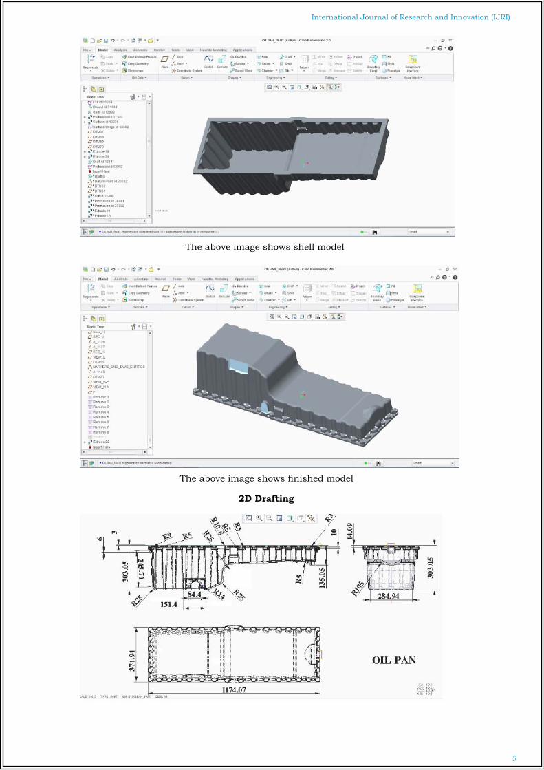
The above image shows shell model
The above image shows finished model
2D Drafting

6
International Journal of Research and Innovation (IJRI)
Die Casting
Introduction
Die casting is a versatile process for producing en-gineered metal parts by forcing molten metal un-der high pressure into reusable steel molds. These molds, called dies, can be designed to produce com-plex shapes with a high degree of accuracy and repeatability. Parts can be sharply defined, with smooth or textured surfaces, and are suitable for a wide variety of attractive and serviceable finishes.Die castings are among the highest volume, mass-produced items manufactured by the metalworking industry, and they can be found in thousands of consumer, commercial and industrial products. Die cast parts are important components of products ranging from automobiles to toys. Parts can be as simple as a sink faucet or as complex as a connec-tor housing.
The Future
Refinements continue in both the alloys used in die casting and the process itself, expanding die cast-ing applications into almost every known market. Once limited to simple lead type, today’s die casters can produce castings in a variety of sizes, shapes and wall thicknesses that are strong, durable and dimensionally precise.
Methods
Die casting is a method of producing alloy castings by injecting molten metal into metallic mold under pressure. Die casting process can be classified intoa) Hot Chamber Processb) Cold Chamber ProcessThe basic die-casting process consists of injecting molten metal under high pressure into a steel mold called a die. Die casting is an efficient, economical process offering a broader range of shapes and com-ponents than any other manufacturing technique. Parts have a longer service life when compared to plastics. Die casting provides complex shapes within closer tolerances than many other mass production processes. Little or no machining is required, and thousands of identical castings can be produced before additional tooling is required. Die casting produces parts that are durable and dimensionally stable, while maintaining close tolerances. Die cast parts are stronger than plastic injection moldings having the same dimensions. Thin-wall castings are stronger and lighter than those possible with other casting methods. Die castings provide integral fas-tening elements, such as bosses and studs.
In this technique, the mould is generally not de-stroyed at each cast but is permanent, being made of a metal such as cast iron or steel. There are a number of die casting processes, as summarized in Figure 2. No Fig No. to the figures
High Pressure Die Casting:
High Pressure Die Casting (HPDC) is a large volume, high productivity process for the production of com-plex, thin walled near net shape castings, with part weights ranging from a few grams to more than 15 kg. It has traditionally been utilized in the produc-tion of housings etc, but this has changed. Pres-ently, feasible products are automotive front end structures and instrument panels in magnesium al-loys and B-pillars in aluminum alloys. Doehler was the first to patent die casting-related technology in 1910. The initial machines produced aluminum castings in reusable metal molds, where a human powered pull bar transmitted the force required to fill the mold. In 1927 the horizontal cold chamber die casting machine was developed, which repre-sents the basics of today’s technology. Gravity Die casting:
A schematic view in below shows the main parts constituting a classical mould for gravity die-cast-ing. Cores (inner parts of the mould) are generally made of bonded sand. Gravity die-casting is suit-able for mass production and for fully mechanized casting.
Low Pressure Die casting: The die is filled from a pressurized crucible below, and pressures of up to 0.7 bars are usual. Low-pressure die-casting is especially suited to the pro-duction of components that are symmetric about an axis of rotation. Light automotive wheels are nor-mally manufactured.
Vacuum die casting The principle is the same as low-pressure die-cast-ing. The pressure inside the die is decreased by a vacuum pump and the difference of pressure forces the liquid metal to enter the die. Thistransfer is less turbulent than by other casting techniques so that gas inclusions can be very limited.
Squeeze Casting
Liquid metal is introduced into an open die, just as in a closed die forging process. The dies are then closed. During the final stages of closure, the liq-uid is displaced into the further parts of the die. No great fluidity requirements are demanded of the liq-uid, since the displacements are small. This process can cast thus forging alloys, which generally have poor fluidities.
High Pressure Die Casting
With different alloy compositions that are common-ly hot- or cold chamber die cast are aluminum, zinc, magnesium and copper-base alloys. The injection system in the hot chamber machines is immersed into the melt and the pressure is therefore limited. The system also degrades quickly if exposed to alu-minum.

7
International Journal of Research and Innovation (IJRI)
In the cold chamber process, the metal reservoir is separated from the injection system. The metal Design Consideration for Die Casting
Some of the important points to be considered while designing are discussed.
Parting Surface Selection
• Manufacturing Consideration• Functional Dimensions• Position of gate• Ejection• Die maintenance• Type of machine• Side cores
Over flows
• Provide area for gases and cold metal to be gathered• Air Vents are provided from overflows• Act as ejector pads• Allow more metal to flow through the system adding heat to the die
Factors Affecting Ejection
• Surface area of the core• Draft on the core• Strength of alloy at election time• Type of ejection• Surface finish of the core• Lubrication on core• Temp of core
Die Design Calculations for Oil Pan
(Mould setup calculations for tonnage with that only we can choose the plate size)a= cavity area (top) =6, 39,037mm2a1= cavity area (left)=263346x2=5,26,692mm2a2= cavity area (right) =87785x2=1, 75,570.4mm2v= volume of component=90, 56,532mm3Density of material (cast iron) =7.81 g/ccW= weight of the component=9.050e-3x70.73kgi =70730gm’sFlow length/wall thick ratio (L/t ratio)
L/t =0 to 100(for mealy thick wall) 100 to 200 (most part’s) 200 to 300(thin walls) 300 and above (difficult to mould special equip-ment)
Shot weight calculations
15% of component air flow = 10,609.5gm’s20% of component air flow = 14,146 gm’sTotal shot weight:Wt. of composite + wt.of over flow+wt. of runner70730+10609.5+14146 = 95,485.5 = 95.5kg’s
Clamping tonnage Required = [Projected area of casting (a) Projected area of over flow (ao) (15% of core) +Projected area of run-ner (ar) (20 % of cavity) +a1+a2] x 1.2 x Specific in-jection pressure= [a+ao+ar+a1+a2]1.2x Specific injection pressure
= [639037+95855+127807+526692+175570.4] x

8
International Journal of Research and Innovation (IJRI) 1.2 x Specific pressure= [15, 64,961.8] x 1.2 x 88 kgf for Cast iron 8 kgf for Aluminum alloy’s (per the standards took from pie book)7 for Bronze= 15649.618x1.2x8 = 150236.33 kg’s/cm2 = 150 ton’sConsidering factor of safety (machine efficiency)150x1.2=180 Ton’s Required clamping tonnage 180 Ton’s
Fill Time and gate calculations
Tacking 0.007 sec or filling time for 0.5 thick wall componentAverage thick of componentFill time tf = 0.007 x 11/0.5 = 0.0385For 1 m2 1.564(m2) x 0.0385 = 0.0602 minQg = (Vol. of comp+ Over flow)/Fill time = 649646.5/0.0602 = 40,278Vg = 50 m/sec flow velocityAg = Qg/Vg = 40,278/50 = 8055.6Ag = Tg x lgGate thick = Tg = 8 mmLength of the gate Lg = Ag/Tg = 8= = 100.695
Fill Ratio
Shot wt of comp/Shot wt capacity of machine= 95.5/1.61 = 59.613 = 59.6%If the fill ratio is < 0.4, which is notDesirable for a sand casting without porosity.So better venting has to be provided for & cope of airProduction Rate / hr0.0602 min for material filling0.5 min for cooling (coolant passage)0.5 min for mould opening & closing
1.0602 min 60/1.0602 = 56.59 56 comp/hrH-180Alxv =180 ton
Horizontal cold chamber-die casting-ra chainLocking unit:
Clamping force/locking force = 180 tonsDie plate=780 x 780Tie bar distance=480 x 480De height = 200 to 550Die stroke = 340Tie bar diameter = 90Ejection unit:Ejection force= 10.5ton’sEjection stroke = 90mmShot weight= 091(less)/1.12(med.)/1.61(max.)No. of shot’s /hr=56no’sHeat input/hr=shot wt. × heat factor × no. of shot’s/hr =95.5x55k cal/kg x 565 shot’s / hr =294140k cal/hrheat lost by equipment 25% =73535 k cal/hr heat to be removed = 2206085 k cal/hrLength n of cooling coil (water inlet pipe for cooling)= (amount of heat to be removed)/(heat removed by an Dia8 hole of 1cm)=220605/45 = 4092cm =40.92m Length of cavity=1150mm = Go for 36 cooling channels
Mould Extraction
A die is usually made in two halves and when closed it forms a cavity similar to the casting de-sired. One half of the die that remains stationary is known as cover die and the other movable half is called “ejector die”.
The die casting method is used for castings of non-ferrous metals of comparatively Low fusion temperature. This process is cheaper and quicker than permanent or sand mould casting. Most of the automobile parts like fuel pump, carburetor bod-ies, Horn heater, wipers, brackets, steering wheels, hubs and crank cases are made with this process.
Core: The core which is the male portion of the mold forms the internal shape of the molding.
Cavity: The cavity which is the female portion of the mold, gives the molding its external form.
The above image is showing oil pan with feed system for the preparation of mould.
9
International Journal of Research and Innovation (IJRI)
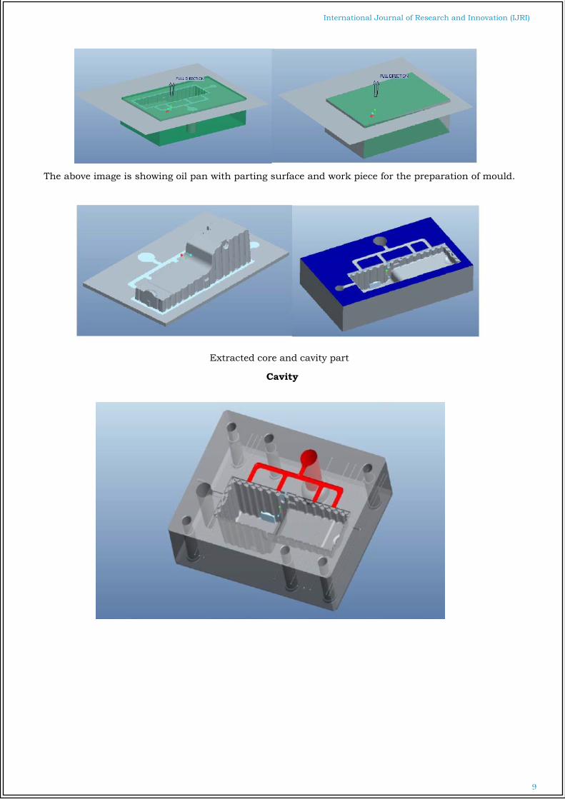
The above image is showing oil pan with parting surface and work piece for the preparation of mould.
Extracted core and cavity part
Cavity

10
International Journal of Research and Innovation (IJRI)
Cavity
The above image is showing 2d drafting of cavity part.
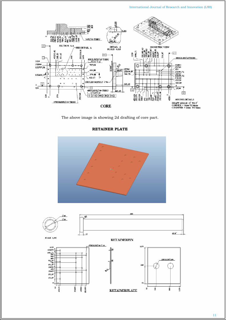
CORE
11
International Journal of Research and Innovation (IJRI)
The above image is showing 2d drafting of core part.
RETAINER PLATE

12
International Journal of Research and Innovation (IJRI)
EJECTOR PLATE
Back Plate

13
International Journal of Research and Innovation (IJRI)
EJECTOR PINS
HOUSING

14
International Journal of Research and Innovation (IJRI)
The above image shows complete mould.

15
International Journal of Research and Innovation (IJRI)
Introduction to Fea
Finite Element Analysis (FEA) was first de-veloped in 1943 by R. Courant, who uti-lized the Ritz method of numerical analysis and minimization of variational calculus to obtain approximate solutions to vibra-
tion systems. Shortly thereafter, a paper published in 1956 by M. J. Turner, R. W. Clough, H. C. Martin, and L. J. Topp es-tablished a broader definition of numerical analysis. The paper centered on the "stiff-ness and deflection of complex structures".
The above image is the imported model of casting tool. Modeling was done in Creo 2.0and imported with the help of IGES (Initial Graphical Exchanging Specification).
16
International Journal of Research and Innovation (IJRI)
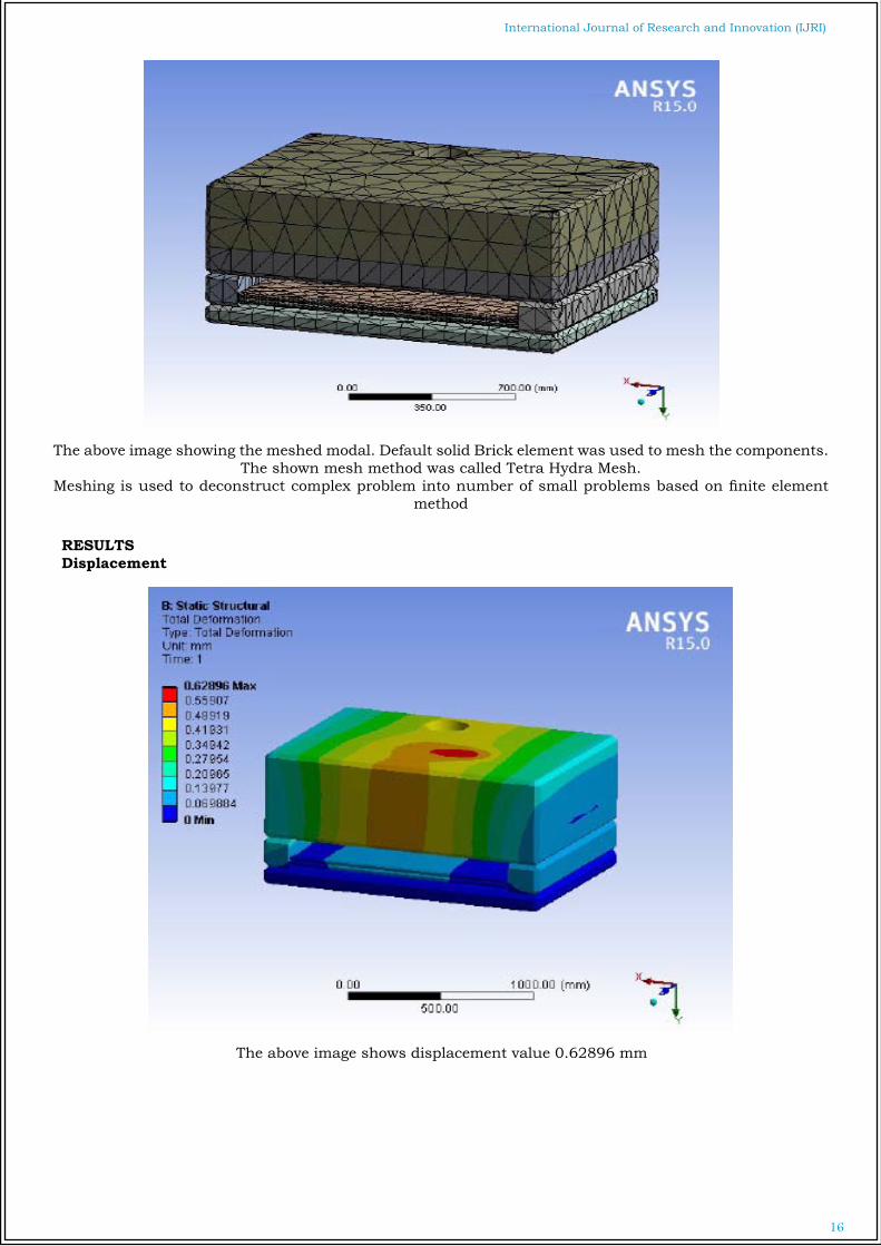
The above image showing the meshed modal. Default solid Brick element was used to mesh the components. The shown mesh method was called Tetra Hydra Mesh.
Meshing is used to deconstruct complex problem into number of small problems based on finite element method
RESULTSDisplacement
The above image shows displacement value 0.62896 mm

17
International Journal of Research and Innovation (IJRI)
The above image shows von-misses stress value 942.99 N/mm2
The above image shows strain value 0.0047982
18
International Journal of Research and Innovation (IJRI)
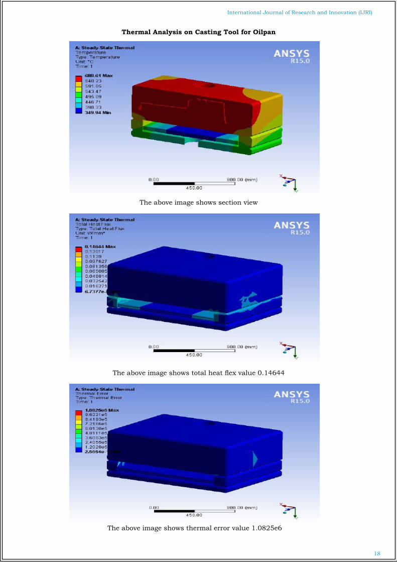
Thermal Analysis on Casting Tool for Oilpan
The above image shows section view
The above image shows total heat flex value 0.14644
The above image shows thermal error value 1.0825e6
19
International Journal of Research and Innovation (IJRI)
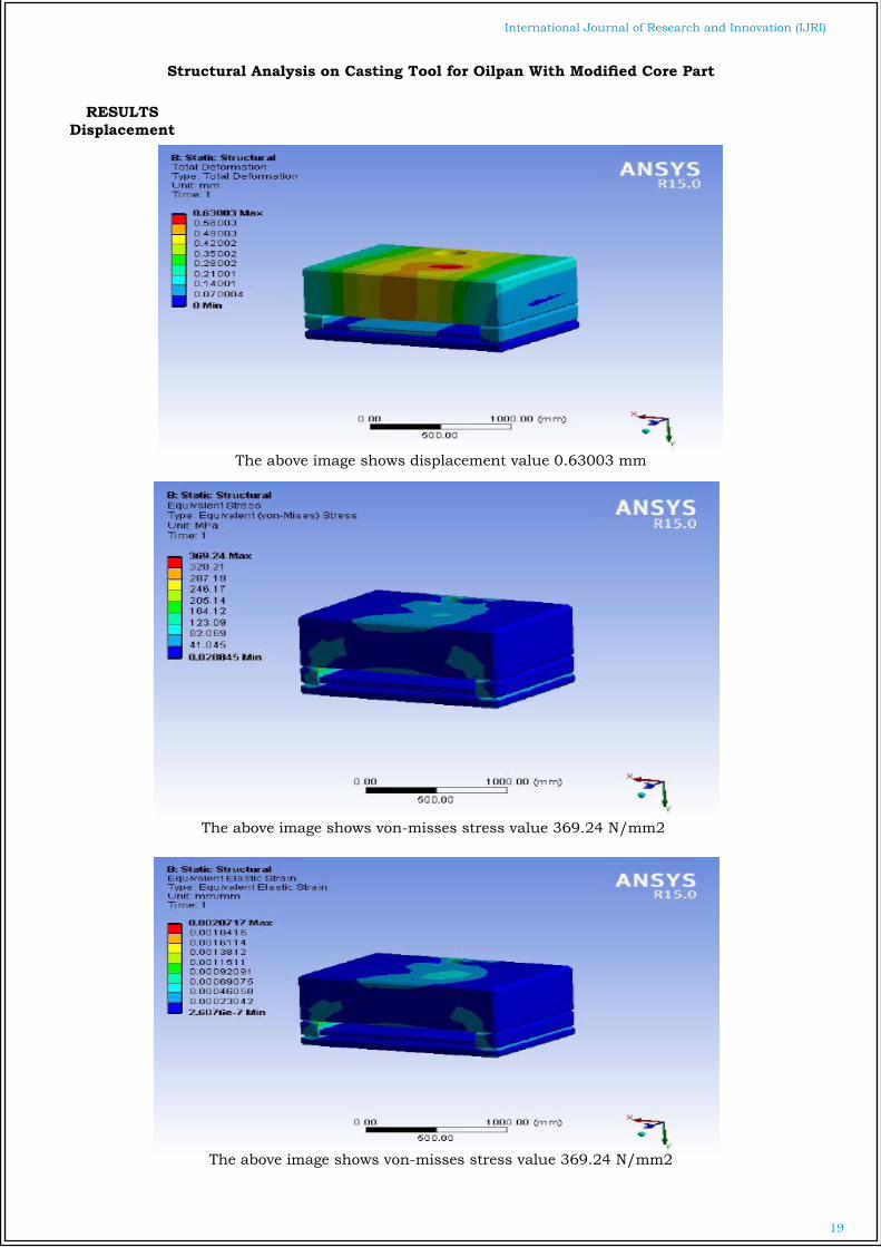
Structural Analysis on Casting Tool for Oilpan With Modified Core Part
RESULTSDisplacement
The above image shows displacement value 0.63003 mm
The above image shows von-misses stress value 369.24 N/mm2
The above image shows von-misses stress value 369.24 N/mm2

20
International Journal of Research and Innovation (IJRI)
Thermal Analysis on Casting Tool for Oilpan With Modified Core Part
The above image shows temperature value 693.46oc
The above image shows total heat flex value 0.17937
The above image shows thermal error value 9.5415e5

21
International Journal of Research and Innovation (IJRI) Manufacturing
This process gives over view of manufacturing process in pro/engineer with step by step images

22
International Journal of Research and Innovation (IJRI)
NC Program for roughing
%G71 O0001N0010T1M06S5500M03G00X-66.809Y-8.G43Z5.H01Z2.G01Z-2.F2500.
Finishing
NC Program for Finishing%G71 O0002N0010T1M06S2347M03G00X-133.853Y-116.832G43Z5.H01Z-50.849G01Z-51.349F1500.

23
International Journal of Research and Innovation (IJRI)
Core Roughing
NC Program for roughing%G71O0001N0010T1M06S10000M03G00X-89.549Y-3.G43Z1.H01G01Z-1.F7620.

24
International Journal of Research and Innovation (IJRI)
Finishing
NC Program for Finishing%G71 O0021N0010T1M06S3500M03G00X-131.91Y-180.674G43Z1.H01Z.409G01Z.209F1200.
Modified CoreRoughing

25
International Journal of Research and Innovation (IJRI)
NC Program for roughing%G71 O0001N0010T1M06S3456M03G00X-2.Y-2.G43Z2.H01Z1.G01Z-2.F2200
FINIFHING

26
International Journal of Research and Innovation (IJRI)
NC Program for Finishing%G71O0004N0010T1M06S10000M03G00X-49.959Y-89.773G43Z2.H01Z-48.904G01Z-49.204F2100.
Casting Tool Design Assembly Results Table
STRUCTURAL ANALYSISEXISTING MODIFIED
Displacement 0.62896 0.63003stress 942.99 369.24strain 0.0047982 0.0020717
THERMAL ANALYSISTemperature 688.61 693.46
Total heat flux 0.14644 0.17937Thermal error 1.0825e6 9.5415e5
ConclusionIn this project the optimization of oil pan using trial and error method is done. This project helps to re-duce the amount and time. In the first step the survey is conducted on oil pan, its manufacturing and cost estimation methods.In the next step oil pan model is prepared using pro/e software for manufacturing and cost estima-tion purposeAnalysis is done on mould structure and plate thick-ness is reduced and re analyzed for the evaluation as per the analysis results plate thickness can be reduced up to 25mm.In the next step the mould calculations are done and prepared mould tool with existing and opti-mized models.As per the thermal analysis modified cooling chan-nel system is right choice for better cooling.In the next step CNC codes are generated for the prepared moulds and mould cost and cost for the
machining process are estimated.It can be concluded that using optimized mould de-signing is more advantages in cost wise and time ef-fective. By using optimized mould industry’s/man-ufacturing body’s can save approximately 68hours of time.
References
1. Kennedy J, Eberhart RC (1995) “Particle swarm optimization”. In: Proceedings of the 1995 IEEE International Conference on Neural Networks (ICNN’95), Perth, Australia, November/December 1995, vol 4, pp 1942–19482. Jerald J, Asokan P, Prabaharan G, Saravanan R (2005) “Scheduling optimisation of flexible manu-facturing systems using particle swarm optimisa-tion algorithm”. Int J AdvManufTechnol 25:964–9713. K.Vidyarthi and M.K.Tiwari. “Machine loading problem of FMS: a fuzzy-based heuristic approach”,

27
International Journal of Research and Innovation (IJRI)
International Journal of Production Research, 2001, 39(5), 953-979.4. M.K.Tiwari, B.Hazarika “Heuristic solution ap-proach to the machine loading problem of an FMS and its Petrinet model”, International Journal of Production Research,1997, 35(8), 2269-2284.5. Swarnkar R, Tiwari MK (2004) Modeling machine loading problem of FMSs and its solution methodol-ogy using a hybrid tabu search and simulated an-nealing-based heuristic approach. Robot Comput-IntManuf 20(3):199–2096. Nagarjuna N, Mahesh O, Rajagopal K (2006) A heuristic based on multi-stage programming ap-proach for machine-loading problem in a flexible manufacturing system. Robot Comput-IntManuf 22:342–352
7. S. G. Ponnambalam, and Low SengKiat (2008) “Solving Machine Loading Problem in Flexible Man-ufacturing Systems Using Particle Swarm Optimiza-tion” World Academy of Science, Engineering and Technology 39 8. SandhyaraniBiswas, S SMahapatra, “Machine loading in Flexible manufacturing System: A swarm optimization approach” Eighth Int. Conference on Opers. & Quant. Management, 2007, NITR, 621-628 9. Kathryn E. Stecke, (1986), “A hierarchical ap-proach to solving machine grouping and loading problems of FMS’S”, European journal of operation-al research, 24, 369-37810. M. K. Tiwari& N.K. Vidyarthi (2000): Solving ma-chine loading problems in a flexible manufacturing system using a genetic algorithm based heuristic approach, International Journal of Production Re-search, 38:14, 3357-338411.Paul S. Andrews, An Investigation into Mutation Operators for Particle SwarmOptimization
12. Akhileshkumar, prakash, MK Tiwari(2006), “Solving machine loading problem of a FMS with constraint based GA”, European Jour-nal of Operational Research 175 (2006) 1043–1069 13. SandhyaraniBiswas, S SMahapatra, “Modified particle swarm optimization for solving machine-loading problems in flexiblemanufacturing sys-tems”. Int J Adv ManufTechnol (2008) 39:931–942
Authors
Maloth.Mohankumar
D.GopichandQualification: m.techDesignation: assistant profressorExperience :4 yr in teaching & 2 yr experience inInfoTech as design engineer