finite element analysis of polyether ether ketone …...finite element analysis solver abaqus v6.10...
TRANSCRIPT
www.vpjournal.net
Original Article Open Access
Kumar et al. Vessel Plus 2019;3:35DOI: 10.20517/2574-1209.2019.006
Vessel Plus
© The Author(s) 2019. Open Access This article is licensed under a Creative Commons Attribution 4.0 International License (https://creativecommons.org/licenses/by/4.0/), which permits unrestricted use,
sharing, adaptation, distribution and reproduction in any medium or format, for any purpose, even commercially, as long as you give appropriate credit to the original author(s) and the source, provide a link to the Creative Commons license, and indicate if changes were made.
Finite element analysis of polyether ether ketone 450G biomaterial used as cardiovascular stent implantVasantha Kumar1, C. M. Ramesha2, V. Sharanraj3
1Department of Mechanical Engineering, Bearys Institute of Technology, Visvesvaraya Technological University, Mangalore 574153, Karnataka, India. 2Department of Mechanical Engineering, Ramaiah Institute of Technology, Bengaluru 560054, Karnataka, India. 3Department of Mechanical Engineering, Sri Jayachamarajendra (Govt.) Polytechnic, Bengaluru 560001, Karnataka, India.
Correspondence to: Prof. Vasantha Kumar, Department of Mechanical Engineering, Bearys Institute of Technology, Visvesvaraya Technological University, Mangalore 574153, Karnataka, India. E-mail: [email protected]
How to cite this article: Kumar V, Ramesha CM, Sharanraj V. Finite element analysis of PEEK 450G biomaterial used as cardiovascular stent implant. Vessel Plus 2019;3:35. http://dx.doi.org/10.20517/2574-1209.2019.006
Received: 9 Apr 2019 First Decision: 18 Jul 2019 Revised: 22 Jul 2019 Accepted: 5 Sep 2019 Published: 19 Sep 2019
Science Editor: Yonghui Ding Copy Editor: Jia-Jia Meng Production Editor: Jing Yu
Abstract
Aim: This research paper aims to modeling and finite element analysis of PEEK 450G biomaterial used as cardiovascular stent implant.
Methods: Commercially available CATIA V5 and ABAQUS 6.0 software were used for modeling and finite element analysis of cardiovascular stent implant to evaluate the radial displacement, stress distribution, and plastic strain in the proximal area of PEEK 450G biomaterial under pressure load conditions of 0.8, 1.0, and 1.2 MPa.
Results: The results show that, both in non-linear bending analysis and non-linear pressure analysis, that PEEK 450G stent exhibits very good radial expansion and lowest stress concentration in plaque and also which is well below the yield level (100 MPa), however plastic strain is quite high.
Conclusion: The blood circulation will be appropriate and also chances of vessel damage may be reduced more. Hence the study reveals that PEEK 450G can be best alternate biomaterial appropriate for cardiovascular stent implant.
Keywords: Biomaterial, polyether ether ketone 450G, biocompatibility, finite element analysis, stent implant
Received: First Decision: Revised: Accepted: Published: x
Science Editor: Copy Editor: Production Editor: Jing Yu

INTRODUCTIONThe innovation of technology in the field of medical and cardiovascular implantation has increased the demand for metal-free restoration and has led to the growth of innovative alternative materials. Biomaterials are frequently used for clinical applications in cardiovascular implantation, dental implants, heart valves, coated hip implants, surgery and for drug delivery “A biomaterial is a non-viable material used in a medical device proposed to interact with biological systems”[1]. Cardiovascular artery disease is the most universal cause of death in the globe[2]. Around 2300 Americans die of coronary disease daily, the average of one death for every 38 s. Every year there are more than 17.9 million of deaths, is projected to rise to 23.6 million deaths by 2030. The total direct and indirect clinical costs of cardiovascular disease are likely to increase to 749 billion $ by 2035[3]. Cardiovascular disease occurs when excess of cholesterol attach to the blood vessels wall, causing coronary artery disease (CAD)[4]. There are different measures are available to revascularise a jammed vessel, including bypass surgery, atherectomy, angioplasty and coronary stenting[3].
Forty years ago, coronary artery bypass surgery was the trendy revascularization action used to cure blocked CAD. Regular coronary closures occur and thus urgent surgery was essential[5,6]. Compared to other possible treatments stenting shows some advantages, has less complications, less pain and also has faster recovery. Therefore, the use of stents in cardiovascular activities has quickly improved from 10% to over 80% in current practice[7]. The present problem in cardiovascular field is that, Co-Cr L605 alloy stent implant has higher modulus of elasticity; owing to higher level of stresses developing in stent expansion which affects the coronary artery, hence chances of vessel damage is very high. In addition, the alloy has very poor plasticity and machinability. Further the presence of Nickel in Co-Cr L605 alloy is a risky aspect from the point of view of allergic problems[8].
Polyether ether ketone (PEEK) boasts of outstanding fatigue resistance and toughness. The Young’s modulus is extremely close to that of the bone. It is available for implantable devices viz cardiovascular, dental, orthopedics and spine applications. In addition, PEEK offers several advantages over metals, were excellent biocompatibility, chemical resistance, and superior in machinability, low co-efficient of friction, lessening of stress shielding.
Ortega-Martínez et al.[9] have studied and recommended PEEK is an alternative material for medical implants because of several advantages over metals. The drawbacks of metals include high elastic modulus which causes high stress, allergies, and radiopacity. Guo et al.[10] have investigated and suggested application of PEEK used as medical implants because of high modulus of elasticity (approximately equal to human bone), and high strength. The excellent biocompatibility and chemical resistance makes PEEK an attractive alternative compared to other biomaterials. Pargaonkar et al.[11] have made comparison between different biomaterials and suggested that PEEK is the excellent biomaterial for medical devices. It has superior biocompatibility, chemically and physically stable, radiolucent and Young’s modulus is similar to bone. Sagomonyants et al.[12] have conducted cytocompatibility and mineralization in vitro studies on pure Titanium alloys and PEEK polymer, and recommended unfilled grade PEEK can propose a versatile base material for medical implants. Since the conventional material such Titanium alloy can release metal and ion debris resulting in blocking the implant area and stress shielding.
By comparison with costly experiments performed in laboratories and hospitals, numerical simulation performed by computers offer benefits of both cost and flexibility. This research article aims to modeling
Page 2 of 13 Kumar et al. Vessel Plus 2019;3:35 I http://dx.doi.org/10.20517/2574-1209.2019.006

and finite element analysis of cardiovascular stent implant to evaluate the radial displacement, stress distribution, and plastic strain in the proximal area of PEEK 450G biomaterial under pressure load conditions of 0.8, 1.0, and 1.2 MPa.
METHODSFinite element analysisAt present there are different coronary stent designs available in the market. In modern days the use of stents in vascular procedures has speedily increased. In order to improve outcome of the coronary stent implantation, it is essential to study the biomechanical performance of the stent before manufacturing and utilized. One of the effective methods used is finite element analysis to study the performance of the cardiovascular stent to alter the design of the coronary stent and its presentation.
Finite element modelsThis section covers modeling of different parts used in the study of biomechanical performance of cardiovascular stents. The modeling of coronary stent, vessel, plaque and balloon are illustrated in Figure 1. Commercially accessible CATIA V5 software was used for modeling and the IGES file was imported in HYPERMESH V11.0 for meshing the model. Figure 2 represents the finite element meshed model of stent, vessel, plaque and balloon.
Cardiovascular stentIn this research article a balloon expandable coronary stent was modeled. To create prime model of cardiovascular stent, commercially accessible software was used. The modeling of cardiovascular stent produced on source of imagery[13]. The stent length = 15 mm, stent outer diameter = 1.915 mm, and stent thickness = 0.05 mm. The element type used for modeling of stent in ABAQUS as C3D8R (linear 8-noded solid element). The FE model of the coronary stent contains of 40,852 elements 108,080 nodes.
Kumar et al. Vessel Plus 2019;3:35 I http://dx.doi.org/10.20517/2574-1209.2019.006 Page 3 of 13
Figure 1. Assemble model of stent, balloon, vessel with plaque
Figure 2. Finite element meshed model of stent, vessel, balloon and plaque

BalloonGeometrical illustration of balloon model was formed based on standard reference[14]. The length of the balloon was 25 mm and as a medium to inflate the coronary stent. The balloon thickness and outer diameter were 0.05 mm and 1.79 mm. To signify the balloon a polyurethane rubber form material was used. The balloon was modeled by using Mooney-Rivlin hyper elastic strain energy potential “W” and polyurethane is incompressible. Like coronary stent, the element type used for modeling of balloon in ABAQUS as M3D8R (linear 8-noded membrane element). The FE model of the balloon consisted of 13,750 elements 13,805 nodes.
VesselThe model of vessel was created by assuming of isotropic and homogeneous material. The vessel was modeled by using hyper elastic Ogden material behavior and as a one- layer blood vessel. The vessel length was 23 mm, vessel outer diameter was 5 mm, and vessel thickness was 0.5 mm. The element type used for modeling of vessel in ABAQUS was C3D8R (linear 8-noded solid element). The FE model of the vessel consisted of 2352 elements, and 111,692 nodes.
PlaqueThere are two types of plaque generated in coronary artery, viz., hypo-cellular and calcified plaque. The hypo-cellular type was used for the modeling of plaque. Geometrical parameters used for the plaque are as follows. Length of plaque = 10 mm, outer diameter of plaque = 4 mm, and thickness of plaque = 1 mm. Element type used for modeling of plaque in ABAQUS was C3D8R (linear 8-noded solid element). The FE model of the plaque consisted of 21,030 elements and 125,390 nodes Non-linear bending analysisThe bending of coronary stent implant has both limitations and advantages. On one side, bending of coronary stent produces elevated stresses on coronary artery; due to these high stresses vessel damage might occur. On other side, the coronary stent bending can facilitate to keep coronary stent steady against the force of pulsate movement of blood. Hence the bending analysis in coronary stent implant can be extremely helpful to alter design of coronary stents. In this article only cardiovascular stent is considered for bending analysis.
Materials properties In this study, the assumption was made that the PEEK 450G biomaterial was homogenous and isotropic characterized by four material properties, i.e., Modulus of elasticity, Density, Poisson’s ratio and Yield stress. The mechanical properties of PEEK 450G biomaterial are represented in the Table 1[15].
Loading and constraintsBased on numerical data for biomedical stent using PEEK 450G biomaterial the deformation of the stent in terms of bending which is dealt as four different loading cases as shown in Table 2[16] and also the one end of the stent is fixed in all DOF.
AnalysisFinite element analysis solver ABAQUS V6.10 was used to find out von-mises stresses of PEEK 450G stent at various loading cases, i.e., 1 mm displacement in Y direction, 2 mm displacement in Y direction with 0.1
MaterialMaterial Properties
Modulus of Elasticity E in (MPa) Density ρ in (kg/mm3) Poisson’s Ratio υ Yield Stress σy in (MPa)PEEK 450G 3700 1.30 × 10⁻⁶ 0.36 100
Table 1. Mechanical properties of PEEK 450G biomaterial[15]
PEEK: polyether ether ketone
Page 4 of 13 Kumar et al. Vessel Plus 2019;3:35 I http://dx.doi.org/10.20517/2574-1209.2019.006

radian rotation in Z direction, 0.15 radian rotation in Z direction and 0.25 radian rotation in Z direction. Figure 3 illustrates the analysis of PEEK 450G biomaterial for the above represented loading cases.
Non-linear pressure analysisHere, coronary stent, balloon and vessel with plaque was considered to carry out non-linear pressure analysis by using commercially available ABAQUS 6.10 software, and to determine radial displacement, von mises stresses and plastic strain of coronary stent when it is subjected to different loading conditions i.e., 0.8 MPa, 1 MPa, and 1.2 MPa. Figure 2 illustrates the FE meshed model of stent, vessel, balloon and plaque was selected for simulation.
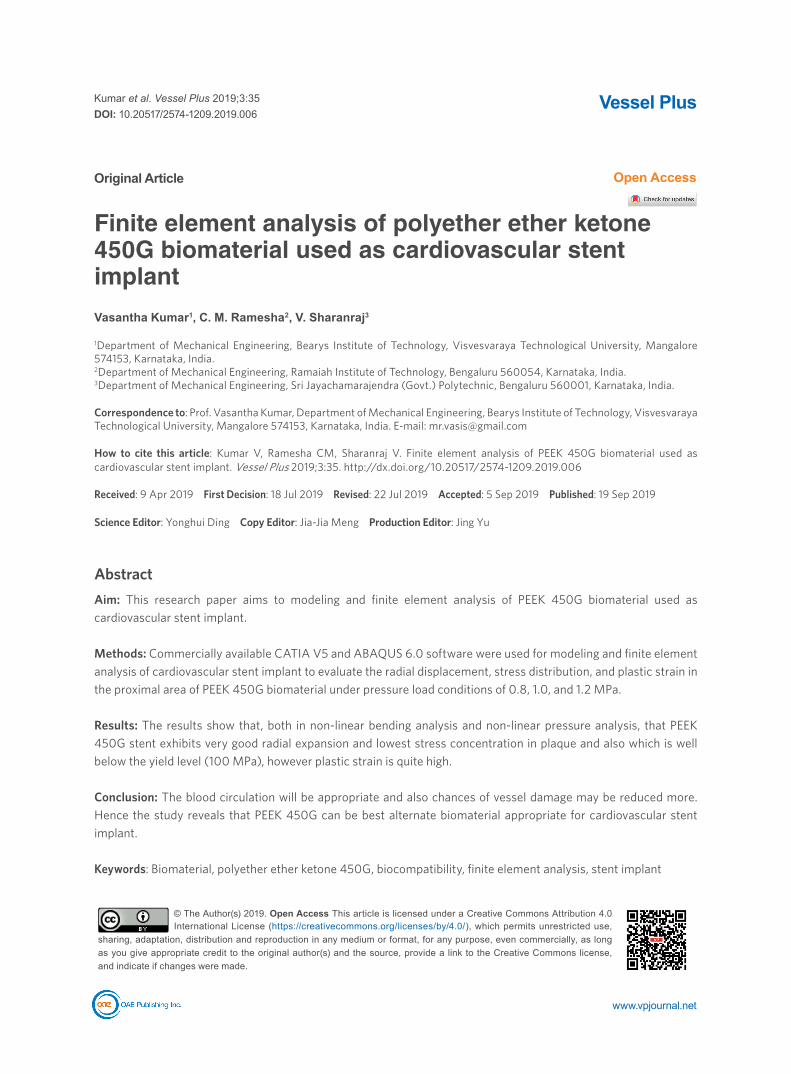
Constitutive stent material behaviorThe stress strain performance determine from the Ogden model is shown in Figure 4[17] with parameters specified in Table 3.
Intima vessel wall was modeled as a single homogeneous hyper elastic layer. Intima vessel layer is stiffer than other layers like media and adventitia, and have only intima vessel is considered for the analysis. Isotropic material properties were used and described by third-order Mooney-Revlin hyperelastic model[18]. The third-order strain energy potential for Ogden model is given by the equation:
Loading cases Displacement-Y in mm Displacement-Z in mmCase-1 1 0Case-2 2 0.1 radianCase-3 2 0.15 radianCase-4 2 0.25 radian
Table 2. Loading cases[16]
A B
C D
Figure 3. Von-mises stress distribution of PEEK 450G stent when subjected to (A) 1 mm displacement (B) 2 mm displacement with 0.1 radian rotation (C) 0.15 radian rotations, (D) 0.25 radian rotations. PEEK: polyether ether ketone
Kumar et al. Vessel Plus 2019;3:35 I http://dx.doi.org/10.20517/2574-1209.2019.006 Page 5 of 13
W = C10 (I1-3) + C01 (I2-3) + C20 (I1-3)2 + C11 (I1-3) (I2-3) + C30 (I1-3)3 (1)
Where, W = Strain energy density function; I1, I2 and I3 = the strain energy invariants; Cij = hyperelastic constants.
The stress-strain behaviour of hypo-cellular and calcified plaque show that, hypo-cellular plaque is less resistance to stretch or deformation than calcified plaque as shown in Figure 5[17]. Hence, in this work hypo-cellular plaque was considered for simulation.
Like blood vessel, here also the similar Ogden hyper elastic model was used, but with first order (i.e., i = 1) and the values are specified in Table 4[17].
Polyurethane rubber material was used for modelling of balloon, by using Mooney-Revlin hyperelastic strain-energy potential, W and is given by the equations:
Figure 4. Stress-stretch curve for intima vessel[13]
Table 3. Ogden model parameters of vessel
Material ρ (kg/mm3) µ1 µ2 µ3 α1 α2 α3 D1
Intima 1.07 × 10⁻⁶ -7.04 4.23 2.85 24.48 25.00 23.54 8.95 × 10⁻⁷
Figure 5. Stress-stretch curve for hypo-cellular and calcified plaque[13]
Page 6 of 13 Kumar et al. Vessel Plus 2019;3:35 I http://dx.doi.org/10.20517/2574-1209.2019.006

W = C10 (I1-3) + C01 (I2-3) + 1/D1 (J-3) (2)I1 = λ1
2 + λ22 + λ2
2 (3)I2 = λ1
2 λ22 + λ1
2 λ32 + λ2
2 λ32 (4)
I3 = λ12 λ2
2 λ32 (5)
Where, C10, C01 and D1 = model co-efficient; J = volumetric stretch; λ1 λ2 λ3 = stretches in 3 principal directions.
The polyurethane material is incompressible and was defined by a non-linear first order hyper-elastic Mooney Revlin model[17]. The stress strain curve for polyurethane rubber balloon is shown in Figure 6, and values of corresponding parameters illustrated in Table 5.
Loading and constraintsTo simulate the inflation process of stent, a pressure was applied to the inner surface of the balloon. The pressure applied was 0.8 MPa, 1.0 Mpa, and 1.2 MPa. In simulation, the balloon has fixed in all degrees of freedom at left end, the balloon were fixed in all degrees of freedom at right end, preventing axial movement of balloon to slide in the artery. Contacts between the balloon and stent, plaque and stent, artery and plaque, were modeled as face-to-face solid contacts, with a frictionless movement under common interaction.
There was no direct contact among any surfaces of the stent model at the beginning of the simulation. When pressure was applied at internal surface of the rubber balloon, first contact between stent and balloon was recognized, then between stent and plaque, and finally between plaque and vessel. In stent expansion, contact between stent and vessel was also noticed.
Table 4. Values of the Ogden model parameters for hypo-cellular plaque
Material ρ (kg/mm3) µ1 α1 D1
Hypo-cellular Plaque 1.45 × 10⁻⁶ 0.093 8.17 4.30 × 10⁻⁷
Table 5. Values of the Ogden model parameters for hypo-cellular plaque
Material ρ (kg/mm3) C10 C01 D1
Polyurethane 1.07 × 10⁻⁶ 1.03176 3.69266 0
Figure 6. Stress-strain curve for polyurethane rubber balloon[13]
Kumar et al. Vessel Plus 2019;3:35 I http://dx.doi.org/10.20517/2574-1209.2019.006 Page 7 of 13

Finite element simulationExplicit solver (ABAQUS 6.10) was used to carry out simulations, which was used to produce to the expansion of the balloon. Considering artery and plaque for the non linear pressure analysis of stent expansion, for the stent inflation balloon was used as a medium for which various pressure load cases was performed to know the mechanical behaviour of artery and stent, such as radial displacement of artery and stent, von-mises stresses sharing of artery and stent and plastic strains at plaque and non-plaque regions.
RESULTSMany researchers elaborated in their work, Co-Cr L605 alloy stent implant has higher modulus of elasticity; owing to higher level of stresses developing in stent expansion which affects the coronary artery during stent expansion, hence chances of vessel damage is very high. To overcome these problems, the alternate material is essential for the cardiovascular stent implants. The results of PEEK450G stent implant has discussed in following two methods.
Non-linear bending analysisVon-mises stressesThe results of non-linear bending analysis of coronary stent by using PEEK 450G as shown in Figure 3. It is observed that the stresses developed in case of PEEK 450G stent when subjected to different loading cases, i.e., 1 mm displacement, 2 mm displacement with 0.1 radian rotation, 0.15 radian rotation and 0.25 radian rotation are 7 MPa, 16 MPa, 11 MPa and 19 MPa as shown in Figure 7. The stresses generated in PEEK 450G is very lesser and well below the yield function of the material, i.e., 100 MPa[15]. The bending of coronary stent causes high stresses on artery may injure the coronary artery[14]. Hence, PEEK 450G has an ideal material in terms of flexibility and stability, also recommended for future coronary stent implants.
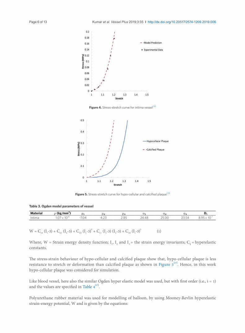
Non-linear pressure analysisRadial displacementThe results obtained for PEEK 450G stent in terms of radial displacement, when subjected to 0.8 MPa pressure load case as shown in Figure 8. Radial displacement of PEEK 450G stent against the expanding pressure at non-plaque region as shown in Figure 9. As can be seen in Figure 9, maximum radial displacement is observed for the maximum pressure of 1.2 MPa. It is observing that the radial displacement of PEEK 450G is 1.4 mm for the pressure load of 1.2 MPa at non-plaque. Figure 10 represents the relation between radial displacement and pressure at plaque region. The radial displacement of PEEK 450G is
Figure 7. Relation among von-mises stresses and different load cases
Page 8 of 13 Kumar et al. Vessel Plus 2019;3:35 I http://dx.doi.org/10.20517/2574-1209.2019.006
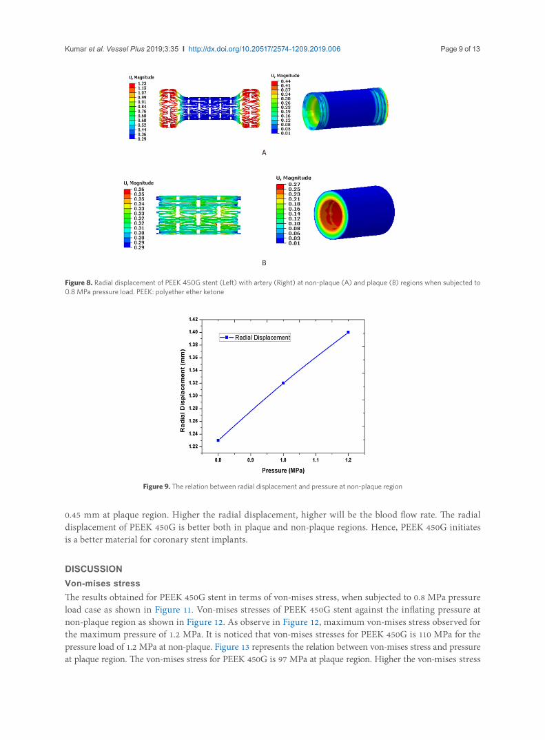
0.45 mm at plaque region. Higher the radial displacement, higher will be the blood flow rate. The radial displacement of PEEK 450G is better both in plaque and non-plaque regions. Hence, PEEK 450G initiates is a better material for coronary stent implants.
DISCUSSIONVon-mises stressThe results obtained for PEEK 450G stent in terms of von-mises stress, when subjected to 0.8 MPa pressure load case as shown in Figure 11. Von-mises stresses of PEEK 450G stent against the inflating pressure at non-plaque region as shown in Figure 12. As observe in Figure 12, maximum von-mises stress observed for the maximum pressure of 1.2 MPa. It is noticed that von-mises stresses for PEEK 450G is 110 MPa for the pressure load of 1.2 MPa at non-plaque. Figure 13 represents the relation between von-mises stress and pressure at plaque region. The von-mises stress for PEEK 450G is 97 MPa at plaque region. Higher the von-mises stress
A
B
Figure 8. Radial displacement of PEEK 450G stent (Left) with artery (Right) at non-plaque (A) and plaque (B) regions when subjected to 0.8 MPa pressure load. PEEK: polyether ether ketone
Figure 9. The relation between radial displacement and pressure at non-plaque region
Kumar et al. Vessel Plus 2019;3:35 I http://dx.doi.org/10.20517/2574-1209.2019.006 Page 9 of 13

in stent, the stiffness of the stent being high, but which may damage the coronary artery[14]. The von-mises stress of PEEK 450G is superior in both plaque and non-plaque regions and also flexible to expand. Thus, PEEK 450G is a better material for coronary stent implants.
Plastic strainThe results obtained for PEEK 450G stent in terms of plastic-strain, when subjected to 0.8 MPa pressure load case as shown in Figure 14. Plastic-strain of the PEEK 450G stent against the inflating pressure at non-plaque region as shown in Figure 15. As observe in Figure 15, maximum plastic-strain observed for the maximum pressure of 1.2 MPa. It is noticed that plastic-strain for PEEK 450G is 61% for the pressure load of 1.2 MPa at non-plaque. Figure 16 represents the relation between plastic-strain and pressure at plaque
Figure 10. The relation between radial displacement and pressure at plaque region
Figure 11. Von-mises stress of PEEK 450G stent at (A) non-plaque region (Left) and (B) plaque region (Right) with (C) artery subjected to 0.8 MPa pressure. PEEK: polyether ether ketone
A B
C
Page 10 of 13 Kumar et al. Vessel Plus 2019;3:35 I http://dx.doi.org/10.20517/2574-1209.2019.006

Figure 12. The relation among von-mises stress and pressure at non-plaque region
Figure 13. The relation among von-mises stress and pressure at plaque region
Figure 14. Plastic strain of PEEK 450G stent at (A) non-plaque region (Left) and (B) plaque region (Right) subjected to 0.8 MPa pressure. PEEK: polyether ether ketone
A B
Kumar et al. Vessel Plus 2019;3:35 I http://dx.doi.org/10.20517/2574-1209.2019.006 Page 11 of 13

region. The plastic-strain for PEEK 450G is 6% at plaque region. The plastic strain of PEEK 450G is higher both in plaque and non-plaque regions, because of softness, material failure begins at yield point so that material may soften and get distorted, finally material fracture may occur. The material starts yielding as the strain rate increases. Hence, the strain rate needs to be minimized by suitably varying its chemical composition.
In this work, 3D modeling of PEEK 450G stent was done by using CATIA V5 and finite element analysis of cardiovascular stent implant were carried out by using commercially available ABAQUS 6.0 software to evaluate the radial displacement, stress distribution, and plastic strain in the proximal area of PEEK 450G biomaterial under pressure load conditions of 0.8, 1.0, and 1.2 MPa. It was clear from FE simulation, both in non-linear bending analysis and non-linear pressure analysis, that PEEK 450G stent exhibits very good radial expansion and lowest stress concentration and also which is well below the yield level (100 MPa), however plastic strain is high because of softness, the strain rate needs to be minimized by suitably varying its chemical composition. Hence, blood circulation will be appropriate and also chances of vessel damage may be reduced more by using PEEK 450G. The FE analysis results showed that PEEK 450G is a best alternate candidate biomaterial suitable for cardiovascular stent implants.
Figure 15. The relation between plastic strain and pressure at non-plaque region
Figure 16. The relation between plastic strain and pressure at plaque region
Page 12 of 13 Kumar et al. Vessel Plus 2019;3:35 I http://dx.doi.org/10.20517/2574-1209.2019.006

DECLARATIONS Authors’ contributions Formulated the problem, designed model and performed FEM analysis: Kumar VWrote the first draft of the manuscript: Kumar V, Ramesha CM, Sharanraj V Discussed the results and implications as well as commented on the manuscript at all stages: Kumar V, Ramesha CM, Sharanraj VRead and approved the final manuscript: Kumar V, Ramesha CM, Sharanraj V
Availability of data and materials Not applicable.
Financial support and sponsorshipNone.
Conflicts of interestAll authors declared that there are no conflicts of interest.
Ethical approval and consent to participateNot applicable.
Consent for publicationNot applicable.
Copyright© The Author(s) 2019.
REFERENCES1. Williams DF. Definitions in biomaterials. Amsterdam - Oxford - New York Tokyo, Elsevier; 1987, pp 24.2. Boston Scientific Corporation or its Affiliates, All rights reserved, USA; 2012.3. Benjamin EJ, Virani SS, Callaway CW, Chamberlain AM, Chang AR, et al. Heart disease and stroke statistics 2018 update: a report
from the American Heart Association. Circulation 2018;137:e67-492.4. David Chua SN, Mac Donald BJ, Hashmi MSJ. Finite element simulation of stent and balloon interaction. J Mater Process Tech
2003;143:591-7.5. Pericevic I, Lally C, Tonner D, Kelly DJ. The influence of plaque composition on underlying arterial wall stress during stent
expansion:The case for lesion-specific stents. Med Eng Phys 2009;31:428-33.6. Garg S, Serruys PW. Coronary stents: Current status. J Am Coll Cardiol 2010;56:S1-S42.7. Yusuf S, Zucker D, Peduzzi P, Fisher LD, Takaro T, et al. Effect of coronary artery bypass graft surgery on survival: overview of 10-
year results from randomised trials by the Coronary Artery Bypass Graft Surgery Trialists Collaboration. Lancet 1994;344:563-70.8. Hanawa T. Materials for Metallic Stents. J Artif Organs 2009;12:73-9.9. Ortega-Martínez J, Farré-Lladós M, Cano-Batalla J, Cabratosa-Termes J. Polyetheretherketone (PEEK) as a medical and dental
material. A literature review. Med Res Arch 2017;5:1-16.10. Guo YT, Chen SG, Wang J, Lu BH. Medical Application of Polyether ether ketone. Transl Surg 2018;3:12-6.11. Pargaonkar SS, Prabhune MS, Patil VV, Deshpande PA, Kolhe VN. A Polyaryletherketone Biomaterial for use in Medical Implant
Applications. Inter J Sci Res Pub 2015;5:1-3.12. Sagomonyants KB, Jarman-Smith ML, Devine JN, Aronow MS, Gronowicz GA. The in vitro response of human osteoblasts to
polyetheretherketone (PEEK) substrates compared to commercially pure titanium. Biomaterials 2008;29:1563-72. 13. Craig B. Open stent design. Westinghouse Drive Fremont. 2012; DOI: 10.6084/M9.FIGSHARE.95614.14. Eshghi N, Hojjati MH, Imani M, Goudarzi AM. Finite Element Analysis of Mechanical Behaviour of Coronary Stent. Proced Eng
2011;10:3056-61.15. VICTREX®, The mechanical properties of PEEK 450G medical document data is considered as per room temperature. 2014;1-4.16. Kumar V, Ramesha CM. Non-linear bending analysis on stent materials used as cardiovascular implants. 2017;4:48-51.17. Schiavone A. Computational modeling of stent deployment and mechanical performance inside human atherosclerotic arteries. Thesis
2015.18. Schiavone A, Qiu TY, Zhao LG. Crimping and deployment of metallic and ploymeric stents-finite element modelling. Vessel Plus
2017;1:1-10.
Kumar et al. Vessel Plus 2019;3:35 I http://dx.doi.org/10.20517/2574-1209.2019.006 Page 13 of 13