finite element based analysis tool for re-entry vehicle tps … · 2005-02-25 · 18th european...
TRANSCRIPT

18th European Thermal & ECLS Software
Workshop, ESA-Estec, 5/10/04, Page 1
Finite Element Based Analysis Tool For ReFinite Element Based Analysis Tool For Re--entry entry
Vehicle TPS AblatorsVehicle TPS Ablators
1818thth European Thermal & ECLS Software WorkshopEuropean Thermal & ECLS Software WorkshopESAESA--Estec, Noordwijk, The Netherlands.Estec, Noordwijk, The Netherlands.
55--1010--20042004
Tom van Eekelen, Tom van Eekelen, SAMTECH s.a.SAMTECH s.a.
18th European Thermal & ECLS Software
Workshop, ESA-Estec, 5/10/04, Page 2
• Hypersonic re-entry into the atmosphere.
• Convection (v3), Radiation
• TPS is needed to maintain low enough temperature• Speed of re-entry (slow/fast)
• Heating rate
• Heating load
Hea
ting
rate
[W/m
2 ]
Heat load [J/m2]
Ballistic entry
AURORA ERC
Apollo
Space shuttle

18th European Thermal & ECLS Software
Workshop, ESA-Estec, 5/10/04, Page 3
• Active systems• Cooling fluid (externally supplied)
• Transpiration/film cooling
• Semi passive systems• Cooling fluid (internally supplied)
• Heat pipes
• Ablators/pyrolysis
• Passive systems• Heat sink
• Insulation
• Re-radiation (hot structure)
• Trade off between:• high heat removal capacity• complexity (possible failure)
18th European Thermal & ECLS Software
Workshop, ESA-Estec, 5/10/04, Page 4
• Insulation of the structure • Maximum allowable structural temperature
• Low density (maximum TPS mass)
• Re-radiation into the environment• High allowable wall temperature
• High emissivity
• Good insulation properties
• Pyrolysis• Endothermic chemical reactions (volume)
• Blocking of boundary conditions
• Ablation• Sublimation (surface recession)
• Blocking of boundary conditions
• Low versus high density ablators:• insulation
• recession rate

18th European Thermal & ECLS Software
Workshop, ESA-Estec, 5/10/04, Page 5
• Material subjected to degradation ( )
• Density ρ varies between ρv virgin and ρc carbonized state
• Degradation will cause Gas mass flow (mig ).
• Surface ablation (removal of material) will take place ( )
Virgin material
Pyrolysis zone
Carbonized material
4
1
2
3
δ
ρ�
ρv
ρc
1 2 3 δ
ρ
18th European Thermal & ECLS Software
Workshop, ESA-Estec, 5/10/04, Page 6
• Heat balance equations:
• Darcy equation:
• Arrhénius equations:
( ) QhmTdt
dhH g
igijijiP +∂−∂∂=+− λρρ
�
( ) ρ�
=∂∂ PK jpi
( ) RTEN
cN
v eA−− −−= ρρρρ 1�

18th European Thermal & ECLS Software
Workshop, ESA-Estec, 5/10/04, Page 7
• User defines properties in « virgin » and « charred » state (dependent on temperature and pressure).
• Program calculates material properties during the analysis (as a function of ρ):
• The constitutive equations define the heat and gas mass flux respectively:
PKm jpgi ∂−=Tq jiji ∂−= λ
RT
PMK
g
g
p µβ=
( )ρ,, cv ccfc =( )ρλλλ ,, cvg=
( )ρββ ,vh=
18th European Thermal & ECLS Software
Workshop, ESA-Estec, 5/10/04, Page 8
• Three types of ablation can de defined:• Mechanical: (explicit definition of ablation speed)
• Chemical: (explicit definition of ablation speed)
• Phase change: (implicit definition of ablation speed)
• Ablation speed is found to satisfy the thermal equilibrium on the surface. qreaction
is due to maximum phase change temperature (contact)
( ) TT
m
E
ebPas−+= τ
�
( )igicc nmPTss ,,
��
=
( )[ ] reactionphwaph qsHHL =−+�
1ηρ

18th European Thermal & ECLS Software
Workshop, ESA-Estec, 5/10/04, Page 9
• Due to ablation, the external surface moves.• Ablation speed perpendicular to external surface
• Mesh moves along « master » lines
• Internal mesh distribution can depend on penetration depth of the temperature
• Two solution strategies:• Convective term added:
• Nodal values re-calculated per time step
y
Tv
x
Tu
dt
dT
Dt
DT
∂∂+
∂∂+=
s�
s�
s�
18th European Thermal & ECLS Software
Workshop, ESA-Estec, 5/10/04, Page 10
• Classical boundary conditions ( ); flux, convection,radiation, etc.• Blocking terms due to injection of material into the surrounding:
• Due to Gas flux ( )
• Due to Ablation ( )
• Gas mass flux blocking term:
• Ablation blocking term:
( ) igi nmPTgq ,−≅
( ) ρsPThq�
,−≅Virgin material
Pyrolysis zone
Carbonized material
s�

18th European Thermal & ECLS Software
Workshop, ESA-Estec, 5/10/04, Page 11
• Applied flux:• Added flux due to combustion of pyrolysis gas
• Blocking terms due to ablation material
• Convective flux (enthalpy formulation):
• Blocking terms due to ablation material and pyrolysis gas
• The enthalpy Hw(T,P) per unit of fluid mass, is automatically calculated using aMollier diagram
phphcccombigi LsHsHnmq ρρ
��
−−+
( )( )( )waphcigiii HHssnmnq −+−−=
��
ρηηα 12
Additional terms
18th European Thermal & ECLS Software
Workshop, ESA-Estec, 5/10/04, Page 12
• 2D/Axis-symmetric finite element mesh with three degrees of freedom per node:
• Temperature (T),
• Pressure (P) and
• Density (ρ)
• Triangular and quadrangular elements• Degree 1 and degree 2 elements
• Fully integrated into SAMCEF Thermal• Steady state & Transient analysis
• Coupling with other elements (3D/Controller)
SAMCEF Amaryllis

18th European Thermal & ECLS Software
Workshop, ESA-Estec, 5/10/04, Page 13
• Test specimen subjected to:• External pressure
• Convection (enthalpy form)• Radiation flux (outward)
• Undergoing:• Chemical ablation
1D thickness calculation
• Pyrolysis• N = 3• E = 99768• A = 107
( ) RTe99768327 14001650.10
−− −−= ρρ�
q
x
y 0=∂∂=
∂∂
x
P
x
T
25 N/m 10.3=P
L=10 mm
18th European Thermal & ECLS Software
Workshop, ESA-Estec, 5/10/04, Page 14
• Conductivity K and capacity C (“virgin” and “charred”)
• Pressure conductivity Kp
• βv = 7.3881 10-13
• µ = 1 10-4
• Mg = 2.8 10-2
1D thickness calculation
T
P
R
MK
g
p µβ=

18th European Thermal & ECLS Software
Workshop, ESA-Estec, 5/10/04, Page 15
• Element distribution:• 25 elements
• 20 elements in a zone of 2.δ(t)
• (δ=penetration depth)
• Blocking terms taken into account:• η1 : blocking due to ablation material
• η2 : blocking due to gas mass flow
• Transient calculation between 0 and 5 seconds.
• Temperature distribution
• at t = 1.0 s
1D thickness calculation
18th European Thermal & ECLS Software
Workshop, ESA-Estec, 5/10/04, Page 16
• Temperature/density evolution at ablation front
• Density distribution
1D thickness calculation
• Gas mass flow
Element 1 Comp. 2
mgtime
Node 2
ρ
time
Node 2
T
time
T= 1 s
T= 5 s
ρ
x

18th European Thermal & ECLS Software
Workshop, ESA-Estec, 5/10/04, Page 17
• Influence of gas mass flow• Temperature evolution
• Large influence on ablation depth (+12.8 %) via:• Gas flow through charred material.• Blocking of convection load.
1D thickness calculation
• Surface recession S
time
T
mg <> 0
mg <>0, η2 = 0
mg = 0
mg, mg <>0
mg <>0, η2 = 0
mg, mg = 0
ss�
,
s
s�
time
18th European Thermal & ECLS Software
Workshop, ESA-Estec, 5/10/04, Page 18
• Ablation of a Carbon sphere
• Material properties for Carbon:• Conductivity
• Capacity• No pyrolysis
2D thickness distribution

18th European Thermal & ECLS Software
Workshop, ESA-Estec, 5/10/04, Page 19
• Axis-symmetric mesh• Re-meshing lines
• Mechanical ablation:• Position and time dependent pressure
• A = 1 10-9
• B = 1.
• TE = 300.
2D thickness distribution
10
1
1189
76
54
2
3
18th European Thermal & ECLS Software
Workshop, ESA-Estec, 5/10/04, Page 20
• Radiation with the environment + radiation load• TR = 300, σε = 5.103 10-11
• Position dependent
• Time dependent
• Convection load (enthalpy formulation)• Position dependent• Time dependent
• Blocking term η2
2D thickness distribution
18th European Thermal & ECLS Software
Workshop, ESA-Estec, 5/10/04, Page 21
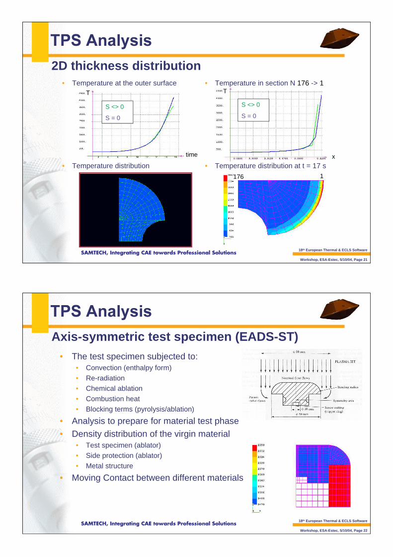
• Temperature in section N 176 -> 1
• Temperature distribution at t = 17 s
• Temperature at the outer surface
• Temperature distribution
2D thickness distribution
S <> 0
S = 0
T
time
T
x
S <> 0
S = 0
176 1
18th European Thermal & ECLS Software
Workshop, ESA-Estec, 5/10/04, Page 22
• The test specimen subjected to:• Convection (enthalpy form)
• Re-radiation• Chemical ablation
• Combustion heat
• Blocking terms (pyrolysis/ablation)
• Analysis to prepare for material test phase• Density distribution of the virgin material
• Test specimen (ablator)• Side protection (ablator)
• Metal structure
• Moving Contact between different materials
Axis-symmetric test specimen (EADS-ST)

18th European Thermal & ECLS Software
Workshop, ESA-Estec, 5/10/04, Page 23
• Pressure at t = 80 s
• Density evolution
• Temperature at t = 80 s
• Temperature evolution
Axis-symmetric test specimen (EADS-ST)
18th European Thermal & ECLS Software
Workshop, ESA-Estec, 5/10/04, Page 24
• Ablation and pyrolysis are:• needed for material characterization
• both necessary for Ablation distribution
• SAMCEF Amaryllis:• is capable of modelling 2D/Axis-symmetric structures of practical complexity
• will be used in the AURORA program: Delta Qualification testing of TPS ablators