finite element modeling of an aluminum tricycle frame · finite element modeling of an aluminum...
TRANSCRIPT

Finite Element Modeling of an Aluminum Tricycle Frame
A. Rodríguez, B. Chiné*, and J. A. RamírezCosta Rica Institute of Technology, School of Materials Science and Engineering, Cartago, Costa Rica
*Corresponding author: P.O. Box 159-7050, Cartago, Costa Rica, [email protected]
Abstract: As a sustainable urban transport
system, the tricycle can represent an adaptive
mobility vehicle used to transport people and bulk
load. This transport system must warranty the
security of its end users, then experimental and
modeling works are very useful tools in order to
evaluate the mechanical performance of its frame.
Finite-element analysis is usually used to fine-
tune the geometry of a design that is still on the
drawing board, before working models are built
and tested. In this work we develop a finite
element model of an aluminum tricycle frame by
using Comsol Multiphysics® 5.2. The static
analysis of the tricycle is carried out with the
Structural Mechanics module by applying
appropriate loading conditions. Stress and
deformation distributions have been evaluated for
different combinations of loads and the analysis
of the structural characteristics of the tricycle
frame has been carried out. The computational
simulations have provided useful insights in
defining the mechanical performance of the
tricycle.
Keywords: aluminum tricycle, solid mechanics,
FEM.
1. Introduction
The MUR-A tricycle was initially developed
in the Design School of the Costa Rica Institute in
Technology. As a sustainable urban transport
system, the tricycle can represent an adaptive
mobility vehicle used to transport people and bulk
load.
The design project was centered on coming up
with a concept for a vehicle that would meet basic
requirements. For this reason, a very simple
mechanical evaluation was made and there is no
warranty that the design will hold up to the efforts,
which it will be subjected to. As a transport
system, the tricycle must ensure the security of its
end users, and as a complex structure, it´s difficult
to evaluate the design in a simple manner.
Experimental and modeling works are very
useful tools in order to evaluate the mechanical
performance of this kind of structures. The main
objective of the study is to detect potential weak
areas in the design and use different analysis and
modelling tools to fine tune the geometry to come
up with the best design, before working models
are built and tested.
To define the loading of the structure we used
bicycle design standards and some published
works of literature. Covill et al. (2014), for
instance, define different load groups that can be
used to analyze the structural strength of a bicycle
frame. Gupta and Rao (2016) instead carried out
a comparative stress analysis for common
aluminum alloys used for mountain bike frames.
Dwyer et al. (2012) applied finite element
analysis to predict fatigue failure locations and
cycles to failure of mountain bike frames. In
addition, they validated the computational results
using the experimental fatigue testings obtained
from the prototype frames.
In the next section we describe the finite
element model of an aluminum tricycle frame
developed with Comsol Multiphysics® 5.2 .
2. Model
As seen on Figure 1, the tricycle consists of
basic standard bicycle parts with a passenger/load
zone on the backside. Only the frame is modeled,
with the rest of the parts (seat tube, bottom
bracket, fork, stem and handlebar) being used to
define the loading conditions.
Aluminum 6063-T83 is the material of the
frame while bottom bracket and handlebars are
made of steel 4130. The Solid Structure Module
is used to define two different 3D FEM models,
Figure 1. Components of the structure.
Excerpt from the Proceedings of the 2016 COMSOL Conference in Munich
COMSOL Multiphysics and COMSOL are either registered trademarks or trademarks of COMSOL AB.

one applying the Beam interface and the second
one the Solid Mechanics (SM) interface.
Further, in case the design needs adjustments,
the results for both models will be compared to
decide whether the Beam model may be used to
make design adjustments before re-modelling the
complete solid by the SM interface. The equations
of the two models are the following:
Solid Mechanics
The conservation equation is:
0 = ∇ ∙ 𝜎 + 𝐹𝑣 (1)
where σ is stress tensor and 𝐹𝑣 are the
volumetric forces.
Then, for linear elastic materials the relationship
between the stress tensor and the small strain
tensor is given by:
𝜎 = 𝐶: 𝜀 = 𝐶(𝐸, 𝑉) (2)
which corresponds to the Hooke’s Law, where C
is the elasticity or stiffness tensor, 𝜀 is the small
strain tensor, 𝐸 is Young’s modulus and 𝑉 is the
Poisson’s ratio.
Beam model
Timoshenko formulation:
𝜕𝑁
𝜕𝑥= 𝑓𝑥
𝜕𝑇𝑦
𝜕𝑥= 𝑓𝑦
𝜕𝑀𝑧
𝜕𝑥+ 𝑇𝑦 = 𝑚𝑧
𝜕𝑇𝑧
𝜕𝑥= 𝑓𝑧
𝜕𝑀𝑥
𝜕𝑥= 𝑚𝑥
𝜕𝑀𝑦
𝜕𝑥− 𝑇𝑧 = 𝑚𝑦 (3)
where N is the normal force, T is the shear, M are
the bending moments and m are the twisting
moments.
3. Methods
The geometry of the tridimensional frame is
imported in Comsol Multiphysics® by means of
the CAD Import Module capabilities. Then the
Solid Structure Module is used to define two
different 3D FEM models, one applying the Beam
interface and the second one the Solid Mechanics
(SM) interface.
Using different colors for each force, Figure 2
shows the loads applied in the different areas of
the tricycle, while Table 1 gives the combination
of loads for acceleration, steady pedalling and
horizontal impact cases.
Figure 2. Loading values.
Table 1. Loading cases.
Loading cases ■ ■ ■ ■ ■ ■
1. Acceleration √ √ √ √
2. Steady
Pedalling √ √
3. Horizontal
Impact √ √
The acceleration case will involve pedaling
forces at the bottom bracket, pulling and pushing
forces at the handlebar and the passenger weight.
The steady pedaling case takes into account only
the passenger and driver weight as the tricycle
rolls along the surface. Finally, the impact case
simulates a sudden impact of the tricycle against
a wall. In this case, we assume that the rider leaves
contact with the seat then only the passenger
weight is considered as well as the impact force.
The British Standard – Mountain-bicycles –
Safety requirements and test methods (2005)
describes the different test used to examine safety
of mountainbike frames. In particular, the Section
4.8.2 indicates how the frame is constrained from
movement during impact testing.
In the computational model, the frame is
constrained from movement in the rear axle, the
fork is allowed to slide only along the horizontal
X and Y axes and the vertical Z displacement is
set to zero on the front axle boundaries. MUMPS
(Beam) and SPOOLES (SM) are the solvers. For
the SM Model, the frame consists of around 6x10⁵
tetrahedral elements (3.3x10⁶ DOFs in the
computations). Figure 3 depicts the mesh of some
components close to the bottom bracket.
Excerpt from the Proceedings of the 2016 COMSOL Conference in Munich

Figure 3. A partial view of the mesh (SM Model).
4. Computational results and discussion
The computational results show that the Beam
model returns higher values both for stresses and
displacements compared to the SM model, while
the zones for the maximum stresses seem to be the
same.
Initially both the Euler-Bernoulli and
Timoshenko formulations were used, obtaining
with the second one results closer to the SM
model’s computations. For instance, in loading
case 1 the maximum von Mises stress for the
Euler-Bernoulli formulation is 1.13E9 N/m2,
while with the Timoshenko formulation we
obtained 9.57E8 N/m2. The second value
compares better to the value of 7.08E8 N/m2
calculated by the SM model. Displacement results
get even closer: 0.082 m (Euler-Bernoulli), 0.031
m (Timoshenko) and 0.018 m (SM).
In all the loading cases, the simulations show
that certain regions of the tricycle might suffer
stresses above the tensile yield strength of 214
MPa and the fatigue limit of 69 MPa. In the latter
case, the fatigue strength value is assumed as the
materials’ resistance after 500x106 fully reversing
load cycles, which is approximately 69 MPa for
Al 6063.
Table 2. Maximum values for von Mises stresses and
displacements.
Load
case
Von Mises stress
(N/m2)
Displacement (m)
Beam SM Beam SM
1 9.57E8 7.08E8 0.031 0.018
2 9.44E8 1.10E9 0.033 0.021
3 9.61E8 6.47E8 0.030 0.010
Figure 4. Elastic limit: steady pedalling case, SM
model.
Figure 5. Elastic limit: steady pedalling case, Beam
model.
Figures 4 and 5 show the results for the steady
pedaling case, where the red areas indicate von
Mises stresses greater than the materials elastic
limit of 214 MPa.
A critical area is observed at the seat tube-
horizontal tube union (the SM model revealing it
just behind the union), as it could be expected
from the compression that the rider’s weight
generate in that area. The Beam model extends
this condition to the area around the seat tube. For
both models, the computational results indicate
that another region to verify is the intersection
between the horizontal and down tubes with the
cage,
In the following plots we depict in red the
areas of the frame and fork which are stressed
above the fatigue limit resistance of the material,
for the steady state pedaling (Fig. 6 and 7) and
acceleration (Fig. 8 and 9) loading cases,
respectively.
Figure 6. Fatigue strength: steady pedaling case, SM
model.
Excerpt from the Proceedings of the 2016 COMSOL Conference in Munich
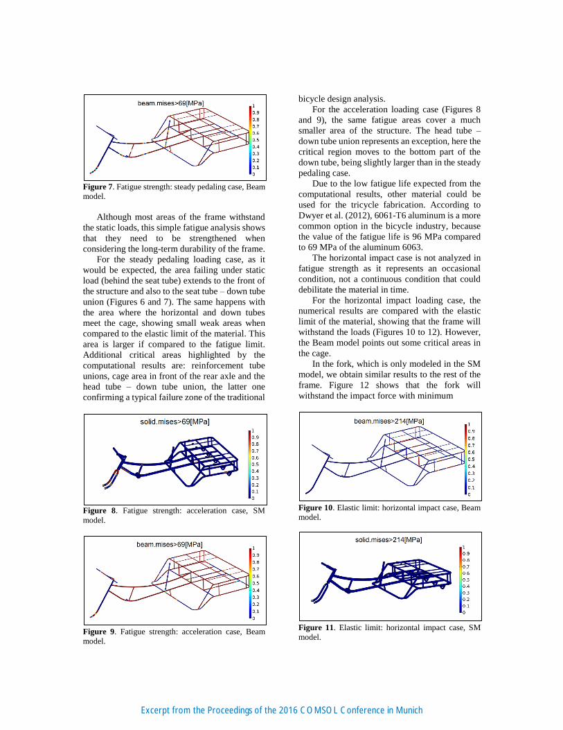
Figure 7. Fatigue strength: steady pedaling case, Beam
model.
Although most areas of the frame withstand
the static loads, this simple fatigue analysis shows
that they need to be strengthened when
considering the long-term durability of the frame.
For the steady pedaling loading case, as it
would be expected, the area failing under static
load (behind the seat tube) extends to the front of
the structure and also to the seat tube – down tube
union (Figures 6 and 7). The same happens with
the area where the horizontal and down tubes
meet the cage, showing small weak areas when
compared to the elastic limit of the material. This
area is larger if compared to the fatigue limit.
Additional critical areas highlighted by the
computational results are: reinforcement tube
unions, cage area in front of the rear axle and the
head tube – down tube union, the latter one
confirming a typical failure zone of the traditional
Figure 8. Fatigue strength: acceleration case, SM
model.
Figure 9. Fatigue strength: acceleration case, Beam
model.
bicycle design analysis.
For the acceleration loading case (Figures 8
and 9), the same fatigue areas cover a much
smaller area of the structure. The head tube –
down tube union represents an exception, here the
critical region moves to the bottom part of the
down tube, being slightly larger than in the steady
pedaling case.
Due to the low fatigue life expected from the
computational results, other material could be
used for the tricycle fabrication. According to
Dwyer et al. (2012), 6061-T6 aluminum is a more
common option in the bicycle industry, because
the value of the fatigue life is 96 MPa compared
to 69 MPa of the aluminum 6063.
The horizontal impact case is not analyzed in
fatigue strength as it represents an occasional
condition, not a continuous condition that could
debilitate the material in time.
For the horizontal impact loading case, the
numerical results are compared with the elastic
limit of the material, showing that the frame will
withstand the loads (Figures 10 to 12). However,
the Beam model points out some critical areas in
the cage.
In the fork, which is only modeled in the SM
model, we obtain similar results to the rest of the
frame. Figure 12 shows that the fork will
withstand the impact force with minimum
Figure 10. Elastic limit: horizontal impact case, Beam
model.
Figure 11. Elastic limit: horizontal impact case, SM
model.
Excerpt from the Proceedings of the 2016 COMSOL Conference in Munich

Figure 12. Elastic limit: horizontal impact case, SM
model, fork region.
deformation areas deformation (areas with lighter
colors), as required by design and test standards.
However, under fatigue analysis, the
computational results show that this component
should be redesigned.
5. Conclusions
A finite element analysis of an aluminum
tricycle frame has been carried out by using
Comsol Multiphysics® 5.2.
For different combinations of loads, the
stress and deformation distributions have
been evaluated using the Beam and the Solid
Mechanics interfaces.
The analysis of the structural characteristics
of the tricycle frame shows that certain
regions of the frame will not withstand the
loads, needing to fine-tune the frame
geometry.
A simple fatigue analysis reveals that the
long-term durability of the design is
compromised, and then additional fatigue
and impact simulations should be developed
in order to improve the design of the tricycle.
Due to the low fatigue life expected from
results, 6061-T6 aluminum could represent
a better choice for the tricycle fabrication.
The FEM simulations have provided useful
insights in defining the structural
performance of the tricycle, gathering
knowledge for future studies.
6. References
COMSOL Multiphysics®, Structural Mechanics
Module User’s Guide version 5.2, (2015).
Covill E., Begg S., Elton E., Milne M., Morris R.,
Katz T., Parametric Finite Element Analysis of
Bicycle Frame Geometries, Procedia
Engineering, Vol. 72, 441-446, (2014).
Gosz M.R., Finite Element Method: Applications
in Solids, Structures, and Heat Transfer, Taylor
and Francis -CRC Press, Boca Raton (FL), USA
(2005).
British Standard, Mountain-bicycles –Safety
requirements and test methods, BS EN
14766:2005 (2005).
Dwyer F., Shaw A., Tombarelli.R., Material and
Design Optimization for an Aluminum Bike
Frame, BSc project, Worcester Polytechnic
Institute (2012).
Gupta R. and S. Rao, Analysis of Mountain bike
frame by FEM, IOSR Journal of Mechanics and
Civil Engineers, 13, issue 2, 60-71, (2016).
Excerpt from the Proceedings of the 2016 COMSOL Conference in Munich