finite element modeling of residual stress profile ... · advances in x-ray analysis, volume 52....
TRANSCRIPT
Finite Element Modeling of Residual Stress Profile Patterns in Hard Turning
Y.B. Guo Dept. of Mechanical Engineering, the University of Alabama, Tuscaloosa, AL 35487, USA
ABSTRACT Hard turning, i.e., turning hardened steels, may produce the unique “hook” shaped residual stress (RS) profile characterized by surface compressive RS and subsurface maximum compressive RS. However, the formation mechanism of the unique RS profile is not yet known. In this study, a novel hybrid finite element modeling approach based on thermal-mechanical coupling and internal state variable plasticity model has been developed to predict the unique RS profile patterns by hard turning AISI 52100 steel (62 HRc). The most important controlling factor for the unique characteristics of residual stress profiles has been identified. The transition of maximum residual stress at the surface to the subsurface has been recovered by controlling the plowed depth. The predicted characteristics of residual stress profiles favorably agree with the measured ones. In addition, friction coefficient only affects the magnitude of surface residual stress but not the basic shape of residual stress profiles. Keywords: residual stress, hard turning, modeling, finite element analysis INTRODUCTION Hard turning and grinding are competitive finishing processes [1,2] for the production of bearings, gears, cams, etc. The selection of hard turning or grinding is made case by case to fit different production scenarios. Process induced residual stress is one key criterion for the process selection and optimization. The most significant differences in the characteristics of residual stress profiles [3-8] by “gentle” hard turning and grinding are manifested in two aspects: (i) hard turning with a sharp cutting edge geometry including honed or chamfered tools generates a “hook” shaped residual stress profile characterized by compressive residual stress at the surface and maximum compressive residual stress in the subsurface. While gentle grinding only generates maximum compressive residual stress at the surface. (ii) The depth of compressive residual stress in the subsurface by hard turning is much larger than that by grinding. However, the magnitude of compressive residual stress at a ground surface is usually higher than that at a turned surface. A worn cutting tool or grinding wheel induces tensile residual stresses at the surface [4,5]. Several studies [7,9] have shown that tool edge geometry is one important process parameter for the residual stress profile by hard turning. The distinct pattern of the residual stress profile by turning has been identified as a critical factor of surface integrity for component performance. A compressive residual stress induced by hard turning and grinding was found to improve rolling contact fatigue life [7,10,11]. Deep compressive residual stresses in the subsurface may be more beneficial to bearing fatigue life than shallower stresses of greater
E-mail address: [email protected] (Y.B. Guo).
344Copyright ©JCPDS-International Centre for Diffraction Data 2009 ISSN 1097-0002Advances in X-ray Analysis, Volume 52
This document was presented at the Denver X-ray Conference (DXC) on Applications of X-ray Analysis. Sponsored by the International Centre for Diffraction Data (ICDD). This document is provided by ICDD in cooperation with the authors and presenters of the DXC for the express purpose of educating the scientific community. All copyrights for the document are retained by ICDD. Usage is restricted for the purposes of education and scientific research. DXC Website – www.dxcicdd.com
ICDD Website - www.icdd.com
Advances in X-ray Analysis, Volume 52
magnitude. Furthermore, tensile residual stress associated with a white layer by hard turning or grinding may reduce rolling contact fatigue life as much as six times [10]. Due to the very importance of residual stress profiles on component performance, a fundamental understanding of residual stress formation and control is essential. However, the formation and control mechanism of the unique residual stress profile by hard turning is not yet known. A few researchers have used finite element methods (FEM) to simulate residual stress profiles in the machined subsurface. Guo [12] has simulated the “hook” shaped residual stress profile in orthogonal cutting annealed 304 stainless steel. Valiorgue, et al. [13] used a traditional heat partition based semi-simulation method to predict the stress in the subsurface in turning 316L steel. However, the method depends on experimentally measured cutting forces and roughly estimated heat flux based on many non-verified assumptions. Rech, et al. [14] simulated a residual stress trend by modeling the action of a single abrasive grain sliding on the workpiece with a certain penetration depth. Unlike the geometrically defined cutting edge geometry in turning, grinding with the undefined cutting edge of abrasives is a much more complex process. Despite these efforts, no simulation models have been established to explain or predict why hard turning generates the unique characteristics of residual stress profiles mentioned above. The most challenging technical hurdle to solve the problem may be due to two major reasons. First, the traditional FEM simulation approaches may not capture the deformation state around the cutting edge, which leads to pseudo residual stress or non-sufficient spatial resolution of residual stress distributions. Second, an effective model of dynamic mechanical properties at microscale around the cutting edge is lacking to capture the complex thermal-mechanical phenomena and their severe gradients which are essential for predicting residual stress. To solve these pressing issues, the objectives of this study are: (a) Develop a new finite element simulation approach for modeling cutting edge/surface interaction such as size effect followed by a coupled thermal-mechanical stress analysis to calculate residual stress profiles; and (b) Develop a physically-based constitutive model of work material to capture the dynamic mechanical behavior at small scale including the size effect induced plowing around the cutting edge. A HYBRID MODELING APPROACH WITHOUT EXPLICIT CHIP FORMATION Plowed depth under the cutting edge The schematic relationship between the cutting edge and material stagnation [15] is shown in Fig. 1. A certain amount of work material is either push upward by the rake face to form the chip or plowed under the cutting edge to become the machined surface. The stagnation point P is the location where the material flow separates to form the chip and the machined surface. Point O is the center of cutting edge, point A is the position where the chip leaves the tool rake face, and point B is the location where the machined surface separates from the tool flank face. PC is the actual material separation line, while BD is the ideal separation line. The plowed depth depends on the cutting edge geometry and can be expressed as
= r (1-cosα) (1) where r is the edge radius and α is the stagnation angle.
345Copyright ©JCPDS-International Centre for Diffraction Data 2009 ISSN 1097-0002Advances in X-ray Analysis, Volume 52
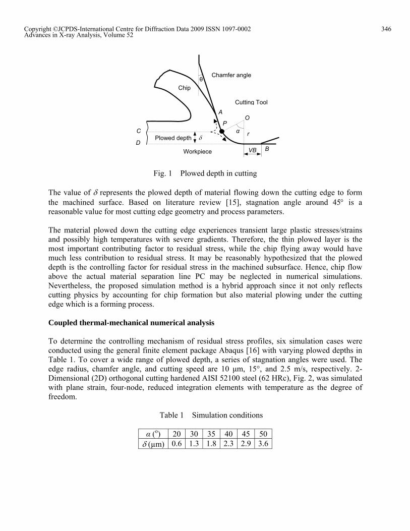
Fig. 1 Plowed depth in cutting The value of represents the plowed depth of material flowing down the cutting edge to form the machined surface. Based on literature review [15], stagnation angle around 45 is a reasonable value for most cutting edge geometry and process parameters. The material plowed down the cutting edge experiences transient large plastic stresses/strains and possibly high temperatures with severe gradients. Therefore, the thin plowed layer is the most important contributing factor to residual stress, while the chip flying away would have much less contribution to residual stress. It may be reasonably hypothesized that the plowed depth is the controlling factor for residual stress in the machined subsurface. Hence, chip flow above the actual material separation line PC may be neglected in numerical simulations. Nevertheless, the proposed simulation method is a hybrid approach since it not only reflects cutting physics by accounting for chip formation but also material plowing under the cutting edge which is a forming process. Coupled thermal-mechanical numerical analysis To determine the controlling mechanism of residual stress profiles, six simulation cases were conducted using the general finite element package Abaqus [16] with varying plowed depths in Table 1. To cover a wide range of plowed depth, a series of stagnation angles were used. The edge radius, chamfer angle, and cutting speed are 10 μm, 15°, and 2.5 m/s, respectively. 2-Dimensional (2D) orthogonal cutting hardened AISI 52100 steel (62 HRc), Fig. 2, was simulated with plane strain, four-node, reduced integration elements with temperature as the degree of freedom.
Table 1 Simulation conditions
α (o) 20 30 35 40 45 50 (µm) 0.6 1.3 1.8 2.3 2.9 3.6
Plowed depth α r
Cutting Tool
Chip
Workpiece VB
C P
B
A O
D
θ Chamfer angle
346Copyright ©JCPDS-International Centre for Diffraction Data 2009 ISSN 1097-0002Advances in X-ray Analysis, Volume 52
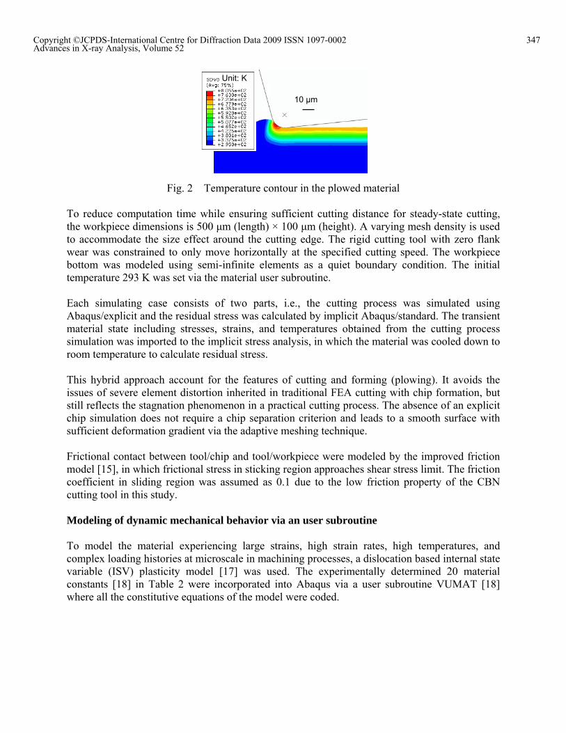
Fig. 2 Temperature contour in the plowed material To reduce computation time while ensuring sufficient cutting distance for steady-state cutting, the workpiece dimensions is 500 μm (length) × 100 μm (height). A varying mesh density is used to accommodate the size effect around the cutting edge. The rigid cutting tool with zero flank wear was constrained to only move horizontally at the specified cutting speed. The workpiece bottom was modeled using semi-infinite elements as a quiet boundary condition. The initial temperature 293 K was set via the material user subroutine. Each simulating case consists of two parts, i.e., the cutting process was simulated using Abaqus/explicit and the residual stress was calculated by implicit Abaqus/standard. The transient material state including stresses, strains, and temperatures obtained from the cutting process simulation was imported to the implicit stress analysis, in which the material was cooled down to room temperature to calculate residual stress. This hybrid approach account for the features of cutting and forming (plowing). It avoids the issues of severe element distortion inherited in traditional FEA cutting with chip formation, but still reflects the stagnation phenomenon in a practical cutting process. The absence of an explicit chip simulation does not require a chip separation criterion and leads to a smooth surface with sufficient deformation gradient via the adaptive meshing technique. Frictional contact between tool/chip and tool/workpiece were modeled by the improved friction model [15], in which frictional stress in sticking region approaches shear stress limit. The friction coefficient in sliding region was assumed as 0.1 due to the low friction property of the CBN cutting tool in this study. Modeling of dynamic mechanical behavior via an user subroutine To model the material experiencing large strains, high strain rates, high temperatures, and complex loading histories at microscale in machining processes, a dislocation based internal state variable (ISV) plasticity model [17] was used. The experimentally determined 20 material constants [18] in Table 2 were incorporated into Abaqus via a user subroutine VUMAT [18] where all the constitutive equations of the model were coded.
Unit: K
10 μm
347Copyright ©JCPDS-International Centre for Diffraction Data 2009 ISSN 1097-0002Advances in X-ray Analysis, Volume 52
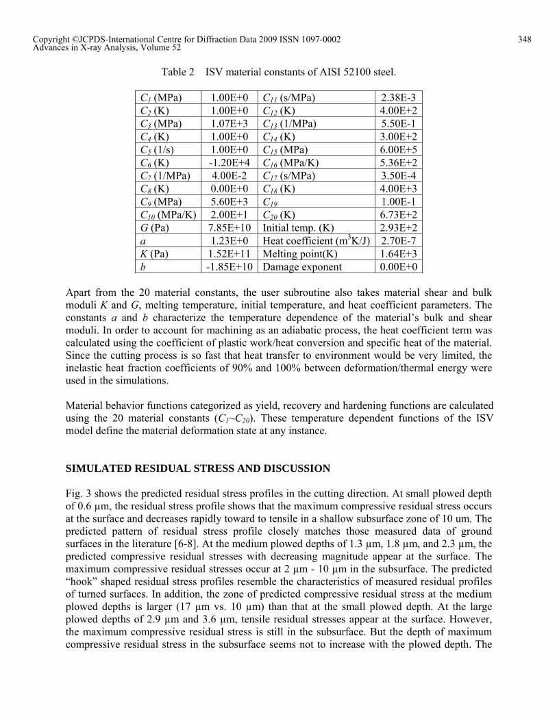
Table 2 ISV material constants of AISI 52100 steel.
C1 (MPa) 1.00E+0 C11 (s/MPa) 2.38E-3 C2 (K) 1.00E+0 C12 (K) 4.00E+2 C3 (MPa) 1.07E+3 C13 (1/MPa) 5.50E-1 C4 (K) 1.00E+0 C14 (K) 3.00E+2 C5 (1/s) 1.00E+0 C15 (MPa) 6.00E+5 C6 (K) -1.20E+4 C16 (MPa/K) 5.36E+2 C7 (1/MPa) 4.00E-2 C17 (s/MPa) 3.50E-4 C8 (K) 0.00E+0 C18 (K) 4.00E+3 C9 (MPa) 5.60E+3 C19 1.00E-1 C10 (MPa/K) 2.00E+1 C20 (K) 6.73E+2 G (Pa) 7.85E+10 Initial temp. (K) 2.93E+2 a 1.23E+0 Heat coefficient (m3K/J) 2.70E-7 K (Pa) 1.52E+11 Melting point(K) 1.64E+3 b -1.85E+10 Damage exponent 0.00E+0
Apart from the 20 material constants, the user subroutine also takes material shear and bulk moduli K and G, melting temperature, initial temperature, and heat coefficient parameters. The constants a and b characterize the temperature dependence of the material’s bulk and shear moduli. In order to account for machining as an adiabatic process, the heat coefficient term was calculated using the coefficient of plastic work/heat conversion and specific heat of the material. Since the cutting process is so fast that heat transfer to environment would be very limited, the inelastic heat fraction coefficients of 90% and 100% between deformation/thermal energy were used in the simulations. Material behavior functions categorized as yield, recovery and hardening functions are calculated using the 20 material constants (C1~C20). These temperature dependent functions of the ISV model define the material deformation state at any instance. SIMULATED RESIDUAL STRESS AND DISCUSSION Fig. 3 shows the predicted residual stress profiles in the cutting direction. At small plowed depth of 0.6 µm, the residual stress profile shows that the maximum compressive residual stress occurs at the surface and decreases rapidly toward to tensile in a shallow subsurface zone of 10 um. The predicted pattern of residual stress profile closely matches those measured data of ground surfaces in the literature [6-8]. At the medium plowed depths of 1.3 µm, 1.8 µm, and 2.3 µm, the predicted compressive residual stresses with decreasing magnitude appear at the surface. The maximum compressive residual stresses occur at 2 µm - 10 µm in the subsurface. The predicted “hook” shaped residual stress profiles resemble the characteristics of measured residual profiles of turned surfaces. In addition, the zone of predicted compressive residual stress at the medium plowed depths is larger (17 µm vs. 10 µm) than that at the small plowed depth. At the large plowed depths of 2.9 µm and 3.6 µm, tensile residual stresses appear at the surface. However, the maximum compressive residual stress is still in the subsurface. But the depth of maximum compressive residual stress in the subsurface seems not to increase with the plowed depth. The
348Copyright ©JCPDS-International Centre for Diffraction Data 2009 ISSN 1097-0002Advances in X-ray Analysis, Volume 52
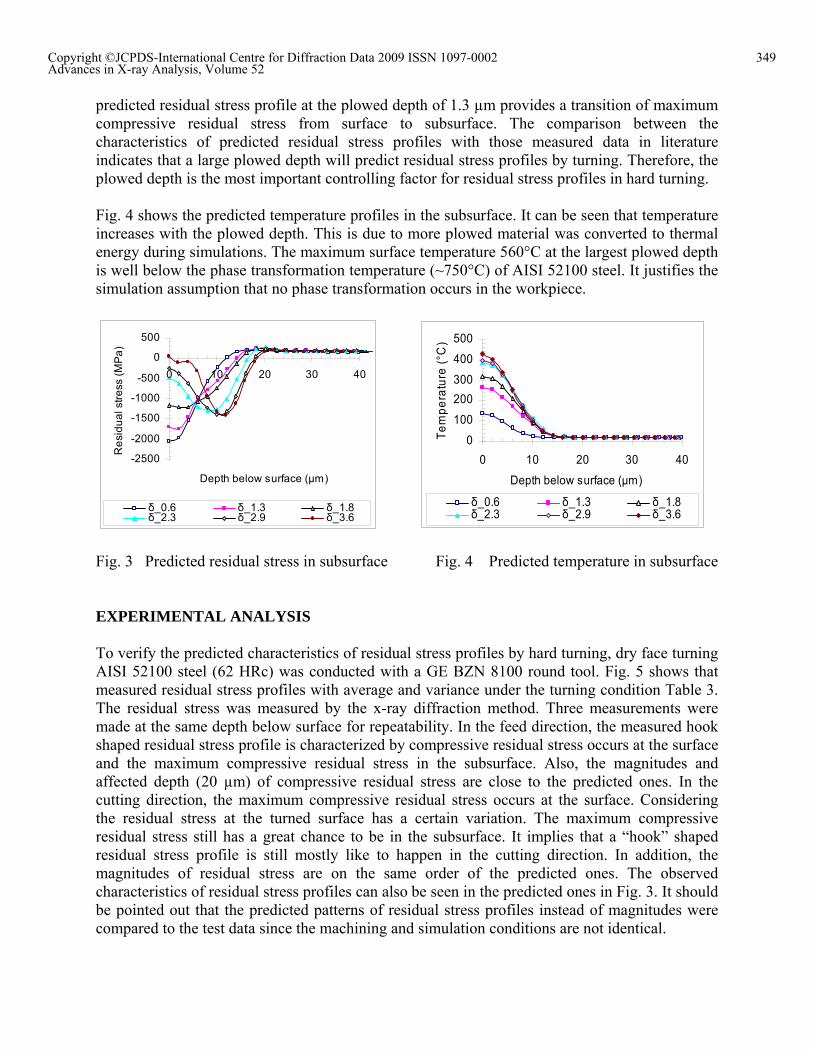
predicted residual stress profile at the plowed depth of 1.3 µm provides a transition of maximum compressive residual stress from surface to subsurface. The comparison between the characteristics of predicted residual stress profiles with those measured data in literature indicates that a large plowed depth will predict residual stress profiles by turning. Therefore, the plowed depth is the most important controlling factor for residual stress profiles in hard turning. Fig. 4 shows the predicted temperature profiles in the subsurface. It can be seen that temperature increases with the plowed depth. This is due to more plowed material was converted to thermal energy during simulations. The maximum surface temperature 560°C at the largest plowed depth is well below the phase transformation temperature (~750°C) of AISI 52100 steel. It justifies the simulation assumption that no phase transformation occurs in the workpiece.
-2500
-2000
-1500
-1000
-500
0
500
0 10 20 30 40
Depth below surface (µm)
Re
sid
ua
l str
ess
(M
Pa
)
δ_0.6 δ_1.3 δ_1.8δ_2.3 δ_2.9 δ_3.6
0
100
200
300
400
500
0 10 20 30 40
Depth below surface (µm)
Te
mp
era
ture
(°C
)
δ_0.6 δ_1.3 δ_1.8δ_2.3 δ_2.9 δ_3.6
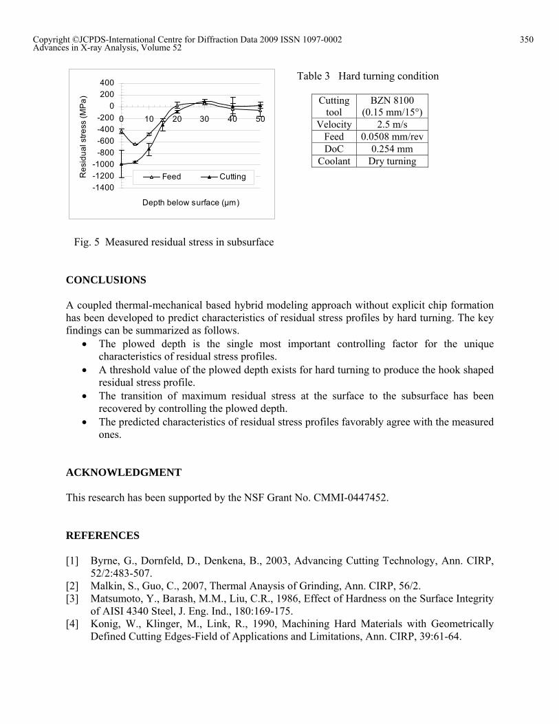
Fig. 3 Predicted residual stress in subsurface Fig. 4 Predicted temperature in subsurface EXPERIMENTAL ANALYSIS To verify the predicted characteristics of residual stress profiles by hard turning, dry face turning AISI 52100 steel (62 HRc) was conducted with a GE BZN 8100 round tool. Fig. 5 shows that measured residual stress profiles with average and variance under the turning condition Table 3. The residual stress was measured by the x-ray diffraction method. Three measurements were made at the same depth below surface for repeatability. In the feed direction, the measured hook shaped residual stress profile is characterized by compressive residual stress occurs at the surface and the maximum compressive residual stress in the subsurface. Also, the magnitudes and affected depth (20 µm) of compressive residual stress are close to the predicted ones. In the cutting direction, the maximum compressive residual stress occurs at the surface. Considering the residual stress at the turned surface has a certain variation. The maximum compressive residual stress still has a great chance to be in the subsurface. It implies that a “hook” shaped residual stress profile is still mostly like to happen in the cutting direction. In addition, the magnitudes of residual stress are on the same order of the predicted ones. The observed characteristics of residual stress profiles can also be seen in the predicted ones in Fig. 3. It should be pointed out that the predicted patterns of residual stress profiles instead of magnitudes were compared to the test data since the machining and simulation conditions are not identical.
349Copyright ©JCPDS-International Centre for Diffraction Data 2009 ISSN 1097-0002Advances in X-ray Analysis, Volume 52
-1400
-1200
-1000
-800
-600
-400
-200
0
200
400
0 10 20 30 40 50
Depth below surface (µm)
Re
sid
ua
l str
ess
(M
Pa
)
Feed Cutting
Fig. 5 Measured residual stress in subsurface CONCLUSIONS A coupled thermal-mechanical based hybrid modeling approach without explicit chip formation has been developed to predict characteristics of residual stress profiles by hard turning. The key findings can be summarized as follows.
The plowed depth is the single most important controlling factor for the unique characteristics of residual stress profiles.
A threshold value of the plowed depth exists for hard turning to produce the hook shaped residual stress profile.
The transition of maximum residual stress at the surface to the subsurface has been recovered by controlling the plowed depth.
The predicted characteristics of residual stress profiles favorably agree with the measured ones.
ACKNOWLEDGMENT This research has been supported by the NSF Grant No. CMMI-0447452. REFERENCES [1] Byrne, G., Dornfeld, D., Denkena, B., 2003, Advancing Cutting Technology, Ann. CIRP,
52/2:483-507. [2] Malkin, S., Guo, C., 2007, Thermal Anaysis of Grinding, Ann. CIRP, 56/2. [3] Matsumoto, Y., Barash, M.M., Liu, C.R., 1986, Effect of Hardness on the Surface Integrity
of AISI 4340 Steel, J. Eng. Ind., 180:169-175. [4] Konig, W., Klinger, M., Link, R., 1990, Machining Hard Materials with Geometrically
Defined Cutting Edges-Field of Applications and Limitations, Ann. CIRP, 39:61-64.
Cutting tool
BZN 8100 (0.15 mm/15°)
Velocity 2.5 m/s Feed 0.0508 mm/rev DoC 0.254 mm
Coolant Dry turning
Table 3 Hard turning condition
350Copyright ©JCPDS-International Centre for Diffraction Data 2009 ISSN 1097-0002Advances in X-ray Analysis, Volume 52
[5] Töenshoff, H.K., Wobker, H.G., Brandt, D., 1995, Hard Turning-Influences on the Workpiece Properties, Trans. NAMRI/SME, 23:215-220.
[6] Abrao, A.M., Aspinwall, D.K., 1996, The Surface Integrity of Turned and Ground Hardened Bearing Steel,” Wear, 196:279-284.
[7] Matsumoto, Y., Hashimoto, F., Lahoti, G., 1999, Surface Integrity Generated by Precision Hard Turning, Ann. CIRP, 48/1:59-62.
[8] Klocke, F., Brinksmeier, E., Weinert, K., 2005, Capability Profiles of Hard Cutting and Grinding Processes, Ann. CIRP, 54/2:557-580.
[9] Brinksmeier, E., Cammett, J. T., Koenig, W., Leskovar, P., Peters, J., Toenshoff, H.K., 1982, Residual Stresses Measurement and Causes in Machining Processes, Ann. CIRP, 31/2:491-510.
[10] Schwach, D,W., Guo, Y.B., 2005, A Fundamental Study on the Impact of Surface Integrity by Hard Turning on Rolling Contact Fatigue,” Int. J. Fatigue, 28:1838-1844.
[11] Hashimoto, F., Guo, Y.B., Warren, A.W., 2006, Surface Integrity Difference between Hard Turned and Ground Surfaces and Its Impact on Fatigue Life, Ann. CIRP, 55/1:81-84.
[12] Guo, Y.B., Liu, C.R., 2002, FEM Analysis of Residual Stress Distribution and Formation Mechanisms in Machining,” Int. J. of Mach. Sci. Tech., 6/1:21-41.
[13] Valiorgue, F., Rech, J., Hamdi, H., Gilles, P., Bergheau, J.M., 2007, A New Approach for the Modelling of Residual Stresses Induced by Turning of 316L, J. Mat. Proc. Tech., 191:270–273.
[14] Rech, J., Kermouche, G., Grzesik, W., Garcia-Rosales, C., Khellouki, A., Garcia-Navas, V., 2008, Characterization and Modelling of the Residual Stresses Induced by Belt Finishing on a AISI52100 Hardened Steel, J. Mat. Proc. Tech., 208:187-195.
[15] Guo, Y.B., Wen, Q., 2005, A Hybrid Modeling Approach to Investigate Chip Morphology Transition with the Stagnation Effect by Cutting Edge Geometry, Trans. NAMRI/SME, 33:469-476.
[16] HKS, Inc., 2007, ABAQUS/Explicit User’s Manual, ver 6.6, Providence, RI. [17] Bammann, D.J., Chiesa, M.L., Johnson, G.C., 1996, Modeling Large Deformation and
Failure in Manufacturing Processes, Theor. App. Mech., 359–376. [18] Guo, Y.B., Wen, Q., Woodbury, K.A., 2006, Dynamic Material Behavior Modeling Using
Internal State Variable Plasticity and Its Application in Hard Machining Simulations, ASME J. Manuf. Sci. Eng., 128:749-759.
351Copyright ©JCPDS-International Centre for Diffraction Data 2009 ISSN 1097-0002Advances in X-ray Analysis, Volume 52