finite element simulation of cooling of realistic 3-d human head and neck
TRANSCRIPT

1
Dennis, Eberhart, Dulikravich & Radons
FINITE ELEMENT SIMULATION OF COOLING
OF REALISTIC 3-D HUMAN HEAD AND NECK
Brian H. Dennis1
Frontier Simulation Software for Industrial Science Collaborative Research Center
Institute of Industrial Science
University of Tokyo
4-6-1 Komaba, Muguro-ku, Tokyo 153-8505, JAPAN
Robert C. Eberhart 2
Department of Surgery and Biomedical Engineering Program
The University of Texas Southwestern Medical Center at Dallas
5323 Harry Hines Blvd. Dallas, TX 75390-9130, USA
George S. Dulikravich 3
Department of Mechanical and Aerospace Engineering, MAIDO Institute
The University of Texas at Arlington, UTA Box 19018, Arlington, Texas 76019, U.S.A.
Steve W. Radons 4
Research & Development, Medtronic Physio-Control Corporation
11811 Willows Road NE, P. O. Box 97006, Redmond, Washington 98073-9706, U.S.A.
1Research Associate. Member ASME. 2Professor of Engineering in Surgery. Fellow ASME. 3Professor. Director of MAIDO Institute. Fellow ASME. 4Manager.

2
Dennis, Eberhart, Dulikravich & Radons
ABSTRACT
Rapid cooling of the brain in the first minutes following the onset of cerebral ischemia is a
potentially attractive preservation method. This computer modeling study was undertaken to
examine brain-cooling profiles in response to various external cooling methods and protocols, in
order to guide the development of cooling devices suitable for deployment on emergency
medical vehicles. The criterion of successful cooling is taken to be the attainment of a 33.0 oC
average brain temperature within 30 minutes of treatment. The transient cooling of an
anatomically correct realistic three-dimensional head and neck with realistically varying local
tissue properties was numerically simulated using the finite element method (FEM). The
simulations performed in this study consider ice packs applied to head and neck as well as using
a head-cooling helmet. However, it was found that neither of these cooling approaches satisfies
the 33.0 oC temperature within 30 minutes. This central conclusion of insubstantial cooling is
supported by the modest enhancements reported in experimental investigations of externally
applied cooling. The key problem is overcoming the protective effect of warm blood perfusion,
which reaches the brain via the uncooled carotid arterial supply and effectively blocks the
external cooling wave from advancing to the core of the brain. The results show that substantial
cooling could be achieved in conjunction with neck cooling if the blood speed in the carotid
artery is reduced from normal by a factor of ten. The results suggest that additional cooling
means should be explored, such as cooling of other pertinent parts of the human anatomy.

3
Dennis, Eberhart, Dulikravich & Radons
NOMENCLATURE
Cp Coefficient of specific heat
hsurf Surface thermal convection coefficient
K Thermal conduction coefficient
Mb Capillary perfusion rate
Q Surface heat flux
qm Metabolic heat source
T Time
V Peak blood speed
x,y,z Cartesian coordinates
ρ Density of the living tissue
θ Temperature
art Artery blood temperature
surf Surface temperature
INTRODUCTION
Rapid cooling of the brain in the first minutes following the onset of cerebral ischemia is a
potentially attractive preservation method. This computer modeling study was undertaken to
examine brain-cooling profiles in response to various external cooling methods and protocols, in
order to guide the development of emergency vehicle portable cooling devices. The devices
considered in this research are non-invasive and would be applied to the external surface of
patent’s head and neck. Specifically, this study considers ice packs applied to the head and neck

4
Dennis, Eberhart, Dulikravich & Radons
as well as a head-cooling helmet. The overall goal is to guide the development of these devices
to obtain a 33.0 oC average target temperature in the brain within 30 minutes of treatment [1] so
that the procedure could be applied by medical emergency vehicle teams. Cooling the brain to a
lower temperature would increase the risk of uncontrolled shivering and cardiac arrest.
Clinical devices and processes for brain cooling, and analytical methods for predicting
temperature distributions have been reviewed [2]. The reason for cooling the brain is justified by
a well-known “Q10 law” of thermal physiology. This law states that for every ten degrees Celsius
reduction in tissue temperature there is a corresponding reduction in brain cell metabolism equal
to the constant Q10. Values for Q10 range from 2.0 to 3.0 and are cited in the physiology
literature. The law is written as
[ ]10/)(10
0m
m o Qqq θθ −= (1)
where θ is temperature and mq is the cell metabolic rate. Assuming a mid range value, say Q10 =
2.5, it is seen that reducing tissue temperature from 37.0 oC to 34.0 oC reduces the metabolic rate
by about 25 percent. These values underscore the promise of cooling for cerebral protection.
During the past few years, several researchers have made attempts at numerically modeling
cooling of oversimplified geometries of a human head while using equally oversimplified
approaches to accounting for the actual diverse tissues in the head [2]. Our group has previously
applied a less sophisticated finite element method to simulate transient brain cooling in a
reasonably simplified two-dimensional cylindrical geometric model of a subhuman primate, the
macaque rhesus monkey [3,4,5]. Cooling was driven either by ice packs applied to the scalp, or

5
Dennis, Eberhart, Dulikravich & Radons
by direct exchange with arterial blood via the heat exchanger in a heart-lung machine, or by both
means. While the computational grid was less intricately prepared than in the current work, the
predictions of that cooling simulation agreed reasonably well with direct experimental
measurements at multiple sites within the brain.
The main benefit of the research effort presented here is that it uses a realistic fully three-
dimensional geometry of an actual human head and realistic values for thermo-physical
properties of a large number of local tissues constituting the head. The numerical algorithm is
also highly accurate and computationally efficient. The results will offer significantly more
definitive answers as to the feasibility of brain cooling via non-intrusive means.
II. FINITE ELEMENT MODEL
An approximate temperature distribution throughout a perfused tissue can be found by solving
bioheat transfer equation suggested by Pennes [6].
martpbp q)(CM)(kt
C +−+∇⋅∇=∂∂
(2)
Here, θart is the arterial perfusion temperature and qm is the heat source due to metabolism. The
perfusion term is MbCp( art - ), where Mb is the capillary perfusion rate, measured in ml. blood
flow per minute per ml. of tissue. This “rate” can be understood as blood flow through the
millions of capillaries in the tissue, proceeding in all directions at once, and thus not having a
vector form. Additionally, we assume temperature-independent material properties and heat

6
Dennis, Eberhart, Dulikravich & Radons
source terms. Under these conditions analytic solutions can be found only for very simple
geometries. For realistic configurations, we must resort to numerical approximations of the
bioheat transfer equation. A finite element method, which is described here, was used [7]. In the
finite element method, the domain where the solution is sought is divided into a finite number of
parts called elements. In this work, tetrahedral shaped elements were used exclusively since
almost any complex 3-D geometry, including a human head, can be decomposed into a finite
number of well-shaped tetrahedral elements.
Applying the method of weighted residuals to Eq. (2) over a single tetrahedral element
Ωe with weight function v results in
Ω
=Ω
−−−∂∂+
∂∂+
∂∂−
∂∂
e
emartpbp dqCM
zyxk
tCv 0)()( 2
2
2
2
2
2
θθθθθθρ (3)
Integrating Eq. (3) by parts once creates the weak statement for the element
( ) ( )
⋅−+
=+∂∂
∂∂+
∂∂
∂∂+
∂∂
∂∂+
∂∂
ee
ee
ee
martpb
epb
ep
dnqvdqCMv
dCMv)z
zv
y
yv
x
xv
k(dt
Cvρ
(4)
Here, e is the element of the surface. Variation of the temperature across the element can be
expressed by

7
Dennis, Eberhart, Dulikravich & Radons
=
=m
iii zyxNzyx
1
),,(),,( θθ (5)
Here, i is an element local node number, m is the total number of element nodes, and N is the
shape function associated with node i. Using Galerkin’s method, the weight function v and the
interpolation function forθ are chosen to be the same. By defining the matrix ][B as
∂∂
∂∂
∂∂
∂∂
∂∂
∂∂
∂∂
∂∂
∂∂
=
zN
zN
zN
yN
yN
yN
xN
xN
xN
B
m
m
m
...
...
...
][
21
21
21
(6)
the weak statement in Eq. (4) can be written in the matrix form as
R]K[t
]C[ eeec
ee =θ+
∂θ∂
(7)
The local stiffness matrix, ][ ecK , the local capacitance matrix, ][ eC , and the right hand side
vector, eR , are evaluated as
epbTe
c dNNCMBBkKe
Ω+= Ω
][][][ (8)

8
Dennis, Eberhart, Dulikravich & Radons
epe dNNCC
e
Ω= Ω
][ ρ (9)
( ) eseartpbm
e dNqdNCMqRee
Γ−Ω+= ΓΩ
θ (10)
for each element in the domain and then assembled into the global system of linear ordinary
differential equations.
][][ RKC c =+ θθ (11)
This global system of equations can be solved to obtain the approximate solution to the bioheat
transfer equation of the entire domain. Here, the time derivative of temperature, θ , is
discretized using a finite difference approximation in time. The Crank-Nicolson algorithm is
used and the final linear system of algebraic equations can be written as
( )nnncnc RRCt
KCt
K 21
][1
][21
][1
][21
11 ++
∆+−=
∆+ ++ θθ (12)
where the subscript n+1 denotes the current time step and n denotes previous time step.
The approximate solution approaches the exact solution as the number of elements is
increased and as the time step size, t∆ , is reduced. However, increasing the number of elements
and increasing the number of time steps also increases the computational cost. Therefore, the

9
Dennis, Eberhart, Dulikravich & Radons
analyst must choose a computational grid and time step size that will give acceptable results in a
reasonable amount of computational time.
The finite element method was implemented in a C++ code. The code was written to be
computationally efficient so that realistic simulations can be performed on a typical personal
computer. The linear algebraic system is solved at each time step using an iterative sparse matrix
solver based on conjugate gradient method with an incomplete factorization for preconditioning
[8]. The solution for the previous time step is used as the initial guess for the iterative solver on
the next time step, which provides enhanced convergence rates. A typical time-accurate
numerical simulation can be performed on a notebook PC (PIII 700 MHz) in less than 20 minutes
using less than 64 MB of in-core memory [9,10,11]. The finite element model and the computer
code used in the present work were verified with a geometrically simple problem for which a
closed form solution is available: excellent agreement was obtained [9,10]. Therefore we have
full confidence in the accuracy of the current FEM results.
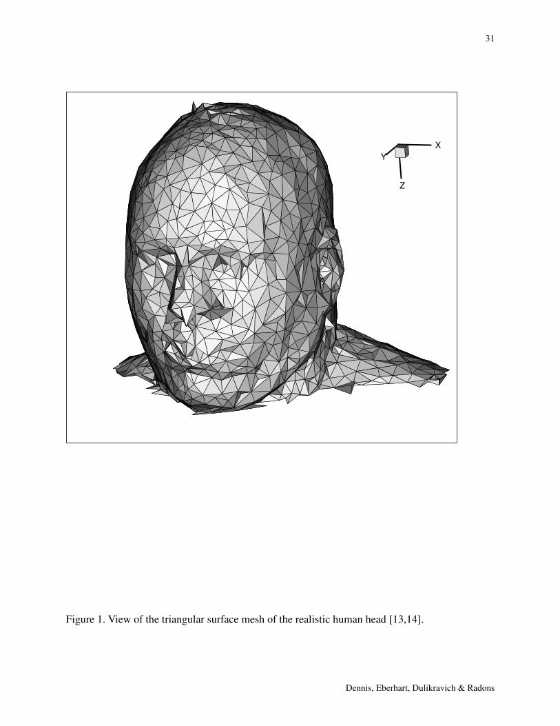
In order to perform a finite element simulation, a geometrical object must first be defined and
discretized into a computational grid made of tetrahedral elements. The head geometry used in
this research was constructed from the National Library of Medicine’s Standard Man data [12],
which was derived from 1 mm thick sections of an entire male cadaver. A three-dimensional
tetrahedral grid of the head was generated from these data by researchers at the University of
Karlsruhe [13,14]. It was composed of 43448 linear tetrahedrons with 14 material property
domains, including air cavities within the head. The triangular surface grid is shown in Figure 1.
The underlying voxel representation we used is the result of the tissue classification of the
Visible Man Dataset by the Karlsruhe University team [13,14]. Capillary “tissue” perfusion data

10
Dennis, Eberhart, Dulikravich & Radons
from an experimental study of rapid brain cooling in a subhuman primate model at the University
of Texas Southwestern Medical Center at Dallas [15,16] was adapted to human tissue types.
Consensus values of thermal parameters for various body tissues were used, as given in Table
1 [15,16,17,18]. The steady state and transient Pennes equations were discretized among all
computational nodes and solved for various initial, boundary and perfusion conditions.
In addition, an idealized neck problem was formulated in order to concentrate on the
convective heat transfer contributions of the carotid artery and internal jugular vein, the primary
conduits for transfer of heat to and from the brain from an ice bath surrounding the neck. This
“countercurrent heat exchanger” problem was formulated for a geometry based on an idealized
neck anatomy derived from the website www.vesalius.com rather than from the discrete NLM/
Karlsruhe data. This was done in part to simplify the problem and in part to adjust the anatomy
of the overdeveloped neck of the cadaver source of the NLM data. Thus, a separate three-
dimensional computational grid was generated for this idealized geometry of the neck in order to
emphasize temperature gradients in the vicinity of the carotid artery and internal jugular vein,
which are relatively close to the neck surface. The head and neck computational grid, thermal
and perfusion parameters and numerical results are available in animation, graphical, and tabular
form at http://maido.uta.edu/~brian/research/head/head.html.
III. NUMERICAL RESULTS FOR HEAD COOLING
Head Cooling With Ice Surface Temperature
In the FEM simulation of cooling of a realistic three-dimensional human head, only the face, eyes
and nose were assumed to be at the steady room temperature of 25.0 oC. The base of the head

11
Dennis, Eberhart, Dulikravich & Radons
was at a steady temperature of 37.0 oC. In all cases, the temperature was monitored at six points
within the brain. The locations of the monitor points are shown in Figure 2. The simulation was
terminated when all six points reached the target temperature of 33.0 oC.
The following four test cases were numerically analyzed:
Case 1. No tissue perfusion and surf = 0.0 oC at t = 0 for the regions covered by a garment
maintained at ice temperature.
Case 2. Tissue perfusion at internal elements, using reasonable values adapted from the UT
Southwestern rhesus monkey experimental hypothermia series [3,4]. The same surface element
boundary conditions as in Case 1 and art = 35.0 oC.
Case 3. A repeat of Case 2 with art = 33.0 oC.
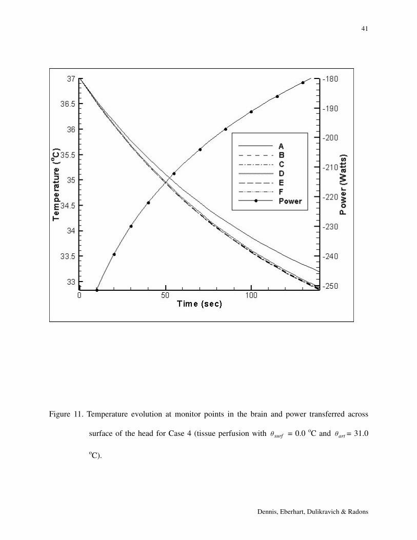
Case 4. A repeat of Case 2 with art = 31.0 oC.
CASE 1. Surface at ice temperature, no perfusion cooling
As shown in Figure 3, without perfusion cooling of the brain, all tissues within the skull cool
very slowly. Brain temperatures do not reach the 33.0 oC target within 30 minutes of the onset of
surface cooling (Figure 4), although the brain did reach this target in 70 minutes (Figure 5). This
result suggests that surface-only cooling at surf = 0.0 oC would not be a viable method for
protection of the brain following the onset of cerebral ischemia.
For possible applications in mobile emergency units, it is of interest to know the energy
requirements for performing the cooling of a brain. The total energy removed via the skin at 70
minutes in this test case was 386kJ requiring a total average power of 92 watts (Figure 6). The
predicted peak power (as estimated by backward extrapolation close to t = 0) was over 200 watts.

12
Dennis, Eberhart, Dulikravich & Radons
The absolute peak power value (at t = 0) was not calculated, since this modeling method requires
extremely small grid sizes and time increments near the surface and at t = 0, and unduly burdens
the model. Furthermore, the instantaneous power level at the sudden onset of surf = 0.0 oC is
unrealistic since in reality a surf = 0.0 oC boundary condition at the skin would be established
over a short period of time (seconds). Currently, it would not be possible to simulate that
temporal change in the surface boundary condition without also modeling the ice-water phase
change, that is, the latent heat effects at the surface of the head.
CASE 2. Surface at ice temperature, perfusion cooling with art = 35.0 oC
In this case the brain still does not reach the 33.0 oC target within 30 minutes of combined
cooling. In fact, a significant portion of the brain does not reach 34.0 oC within 30 minutes
(Figure 7). The reason for this is that the art = 35.0 oC counteracts the conduction-based
cooling from the surface. The predicted total energy removed from the skin surface was 1700 kJ
(Figure 7), which is irrelevant, since the 33 oC was not reached.
CASE 3. Surface at ice temperature, perfusion cooling with art = 33.0 oC
With entering arterial blood cooled at art = 33.0 oC the brain reaches the 33.0 oC target after
approximately 7.5 minutes (Figures 8, 9 and 10). It was predicted that a total of 94.7 kJ needs to
be removed at an average rate of 210 watts and a near-initial peak power of 250 watts (Figure 8).
This means that less total energy needs to be removed than in Case 1, but the average and peak
powers are higher, due to the additional cooling load of the incoming blood to the brain.

13
Dennis, Eberhart, Dulikravich & Radons
CASE 4. Surface at ice temperature, perfusion cooling with art = 31.0 oC
With blood pre-cooled at art = 31.0 oC the brain reaches the 33.0 oC target at approximately two
minutes (Figure 11). A total of 44.8 kJ had to be removed at an average power of 344 watts and a
near initial peak power of 250 watts (Figure 11).
It is important to remember in Cases 2, 3 and 4 that the energy load associated with cooling
the arterial blood to the specified temperatures was not included. Assuming the arterial blood
enters the head/neck region at the normal temperature of art = 37.0 oC, with an arterial blood
flow rate of 250.0 ml/min (which is less than normal), the additional average power load for 60
minutes of neck cooling would be 20 watts.
Cases 1-4 suggest that brain cooling to the target level of 33.0 oC within 30 minutes is
feasible if the arterial supply can be accessed and the arterial temperature reduced to these levels
(at least art = 33.0 oC). Thus, efforts should be made to cool the arterial blood, examining all
possible modalities. By inference, these results suggest that the brain may cool to the target level
in time, if the head surface temperature surf = –15.0 oC is applied.
The perfusion-assisted results of Cases 2-4 agree in general with the experimental results of
the UT Southwestern study of primates [3,4] and underscore the importance of the blood-based
convective mechanism in tissue cooling. The midline temperature profiles in the animations of
Cases 3 and 4 indicate more rapid cooling of the cortical and subcortical regions than deeper
structures. This is expected, since the conduction pathway is shorter to these regions than to the
deeper structures, and there is some lateral conduction owing to the curvature of the skull.
A principal assumption of this analysis is that the perfusion distribution is uniform for all brain
substructures, albeit significantly higher than for non-cerebral structures.

14
Dennis, Eberhart, Dulikravich & Radons
Of course, the patient with a cerebral ischemic event would not benefit from perfusion-
cooling of the region of ischemia. This would imply that convective cooling would not be
available, and that the region most in need of the protection of lower temperature would not
receive it. However, brain perfusion distribution is quite volatile in healthy subjects, with blood
flow rapidly shifting to regions experiencing high metabolism, as elegantly demonstrated by
functional SPECT and MRI studies. This raises the important question of the regulation of blood
supply to regions adjacent to the ischemic region: how, if at all, is the perfusion of these regions
affected? Speculating for the moment that perfusion is unaltered in the adjacent regions; one
may envision a potentially dangerous region of warm ischemia, surrounded by better-perfused,
cooler tissues. In contrast to the results of cerebral hypoxia modeling, thermal diffusion is much
higher than oxygen diffusion. Thus, a larger region might be afforded partial metabolic
protection, even if oxygen cannot be delivered.
It should also be noted that perfusion cooling in the vicinity of an ischemic area would
enhance ischemic region cooling, so long as the blood perfusate is at a lower temperature than
the ischemic tissue. Conversely, if the blood perfusate is at a higher temperature than the
conduction-cooled tissue, such as might occur in the vicinity of a near-surface ischemic region,
the surface cooling effect would be blunted by the warm blood perfusate.
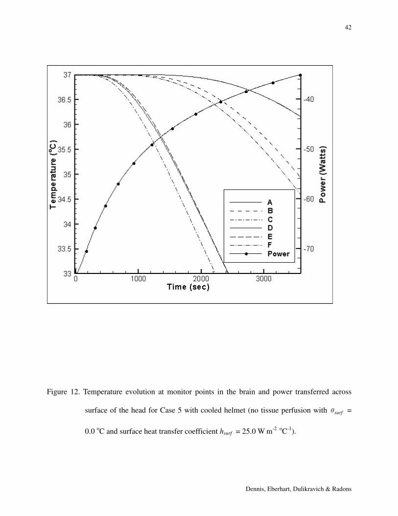
Head Cooling With a Convection Cooled Helmet
In this sequence of FEM simulations of brain cooling, a realistic three-dimensional human
head was assumed covered by a cooling helmet [1]. The helmet has been simulated with
convection boundary conditions on the regions where the helmet would contact the head. The
face, eyes and nose were assumed uncovered and maintained at room temperature of 25.0 oC.

15
Dennis, Eberhart, Dulikravich & Radons
The following three test cases were analyzed:
Case 5. No tissue perfusion and surface heat transfer coefficient hsurf = 25.0 W m-2 oC-1 (derived
from [1]).
Case 6. Tissue perfusion with art = 37.0 oC at all internal elements of the head. The perfusion
distribution was identical to this of Case 2.
Case 7. All other conditions were the same as in Case 6, but hsurf = 46.0 W m-2 oC-1 (the highest
value observed in [1]).
CASE 5. Surface convection cooling via helmet applied at t = 0, with a circulating cooling
fluid at 5.5oC. No tissue perfusion.
Temperature profiles predicted at six points within the brain (Figure 2) are given in Figure 12. At
30 minutes the outer cortical positions (C, D, E) have cooled below 35.0 oC. However, the inner
cortical regions are only beginning to cool. The heat extracted from the head (input power)
calculated for that portion covered by the cooled garment is shown in Figure 12. The total heat
extraction over 60 min is 150 kJ.
CASE 6. The surface convection conditions of Case 5, with art = 37.0 oC tissue perfusion.
The temperature evolution profiles predicted at the six sites in the brain are shown in Figure 13.
There is negligible cooling (less than 0.1oC) at all sites at 30 minutes. Brain cooling is less
efficient when a helmet is interposed between the scalp and the cold source. This is more evident
when the cooling fluid is at 5.5oC rather than the ice temperature of Case 2, and even more
evident when no pre-cooling of the cerebral arterial blood is assumed, also as in Case 2. These

16
Dennis, Eberhart, Dulikravich & Radons
results emphasize the conclusions of Cases 1-4, that cooling of cerebral arterial blood (performed
extracranially) is necessary.
Case 7. The surface convection coefficient is increased to 46 W m-2 oC-1, the highest value
extracted from the cited experimental study [1]. Other conditions as in Case 6.
Almost doubling the convective heat transfer coefficient of Case 6 provides negligible cooling of
the brain (Figure 14).
IV. NUMERICAL RESULTS FOR NECK COOLING
Due to the need to cool the blood perfusing the brain, it was decided to numerically simulate
independent means of cooling of the neck. The objective was to learn if neck-only cooling would
be sufficient to reduce the arterial blood temperature before it enters the brain. The neck-only
geometric model was created where cylindrical neck, cervical vertebral, tracheal and carotid
arterial and jugular venous dimensions were estimated from the www.vesalius.com website data.
Due to symmetry, only half the neck was modeled (Figure 15) with different tissue regions shown
in Figure 16.
In the neck model, the chest (bottom) portion of the neck was set to 37.0 oC except at the vein
outlet. The top of the neck model used an insulating thermal boundary condition except for the
vein inlet and artery outlet. With this boundary condition, the head and neck models can be
uncoupled, which significantly reduces the computational cost. Use of this boundary condition
implies the temperature in the bottom of the head and the top of the neck is the same, which is a
conservative assumption.

17
Dennis, Eberhart, Dulikravich & Radons
Carotid arterial entry temperature was art = 37.0 oC. Jugular vein entry temperature was
arbitrarily set at 33.0 oC, to simulate target temperature cooling of the brain achieved from other
sources (helmet, pharynx, axilla, etc.). For all cases that were analyzed, a steady, fully developed
blood flow was assumed in both the artery and the vein. A zero normal heat flux was set at both
the vein and artery outlet. The peak arterial blood velocity was varied from high-normal (Vmax =
0.5 m s-1) to very low (Vmax = 0.05 m s-1) as might be assumed in case of a severe stroke. The
time averaged high-normal peak velocity was estimated from plotted vector Doppler-ultrasound
measurements found on the www.nwra.com website.
The following case was simulated numerically.
Case 8. No tissue perfusion was assumed and surf = 0.0 oC was applied at the neck surface thus
simulating countercurrent heat exchange between jugular vein and carotid artery. Various values
of peak arterial blood velocity were used.
CASE 8. Steady state ice cooling of the neck with countercurrent heat exchange between
jugular vein and carotid artery.
In this case a steady state simulation of the neck cooling was performed. The perfusion in the
neck tissue was neglected since the perfusion constant is relatively small. This represents a best
possible case and was used to determine the lowest possible arterial blood outlet temperature
achievable with various carotid blood peak velocities. Figure 17 depicts the steady state
temperature distributions for Vmax = 0.5 m s-1 on a slice through the neck that goes through both
artery and vein. The cooling front does not reach the artery in these views. It is blocked by the
countercurrent heat exchange from the warmer 33oC down-coming venous blood. At the
elevation of the base of the skull (14 cm) the centerline carotid arterial blood has still not begun

18
Dennis, Eberhart, Dulikravich & Radons
to cool below 37.0 oC. However, the bulk average blood temperature shows a modest impact of
neck cooling, despite the blocking thermal effect of the countercurrent exchange. The average
computed temperature in the artery for various locations in the neck is shown in Table 2.
However, it is important to note that tissue perfusion at arterial temperature, which would
warm the blood, was not included in this simulation. Figure 18 depicts the steady state artery
outlet temperature profile for various values of peak blood velocity in the artery. The average
outlet temperatures for the profiles in Figure 18 are listed in Table 3.
For normal carotid blood flow rates, even in the steady state, the artery outlet temperature
cannot be significantly reduced from 37.0 oC. However, the simulations show that the blood in
the artery can be cooled significantly if the blood velocity is reduced by a order of magnitude
from its normal value.
It should be pointed out that the time averaged peak speed for the carotid blood is around V =
0.5 m/s. It is likely even higher than that considering the range of mass flow rates quoted in the
literature. For the case of peak blood speed V = 0.5 m/s, the computed results show only slight
cooling of the blood at the artery outlet. This agrees with theoretical and experimental data since
a peak blood speed V = 0.5 m/s is most often used. The purpose of using different peak average
blood speeds in the simulations was to show what could be achieved if the blood flow rate would
be reduced.
V. DISCUSSION
The perfusion term in the Pennes equation is MbCp( art - ) where Mb is the capillary perfusion
rate, measured in ml. blood flow per minute per ml. of tissue. This “rate” can be understood as

19
Dennis, Eberhart, Dulikravich & Radons
blood flow through the millions of capillaries in the tissue, proceeding in all directions at once,
and thus not having a vector form. Furthermore, the extremely small capillary diameters and the
relatively low blood velocity in the capillaries ensure that the blood temperature equilibrates with
that of the immediately surrounding tissue before the blood leaves the capillaries. The magnitude
of this perfusion heat flow term is, in general, much larger than the conduction heat flow term for
temperature gradients achievable in human thermal physiology. Comparison of conduction-only
versus perfusion plus conduction heat exchange in an experimental animal series amply
demonstrates this important point [3,4].
Therefore, only by artificially cooling the arterial blood was it possible to cool the brain in the
specified time (Cases 3, 4). Even pre-cooling arterial blood to art = 35.0 oC did not achieve
33.0 oC global cooling of the brain within 30 minutes! The helmet with 5.5oC coolant did no
better when the protective effect of warm perfusion was included; the core of the brain was not
cooled within 30 minutes for any condition (Cases 6 and 7). Ice bath cooling of the neck,
provided a small measure of carotid arterial precooling of the brain resulting in art = 35.5 oC
average arterial temperature at 30 minutes. However, the model did not include tissue perfusion
with warm blood, which would have substantially reduced the cooling effect.
All of this suggests that other cooling means should be explored, including: 1) combinations
of currently considered external cooling methods; 2) other external methods not yet addressed; 3)
internal cooling methods [20].
There are other appealing external cooling methods. Ice conditions can be applied to the
axillae, and groin, regions with good coupling to arterial and venous supplies. The turbinate
sinuses and pharynx, proximal to the undersurface of the frontal brain, can be convectively
cooled with sublimating oxygen crystals.

20
Dennis, Eberhart, Dulikravich & Radons
Finally, there are invasive methods, including swallowing of cold fluids, and blood access
technologies which might be considered. These are less desirable because of technical
considerations, the advanced degree of knowledge and training that would be required, and the
danger of embolization of the carotid arterial plaque burden frequently observed in stroke
patients. As shown in successful clinical trials, the cooling effect of 4.0 oC saline (1 to 2 liters)
injected in the main artery would be much larger and more immediate [20] than that of any test
case studied in this paper. However, this cooling effect would be transient, not continuous, and it
would require an invasive procedure.
VI. CONCLUSIONS
The simulations of cooling methods considered to date all indicate that no single means of
external cooling of the head or neck is sufficient to reach the 33.0 oC target temperature in a
reasonable period of time. Specifically, for the iced surface of the head, inclusion of the warm
blood perfusion term effectively blocks the cooling wave from advancing beyond a few
millimeters at 30 minutes.
The central conclusion of insufficient cooling is supported by the modest cooling
enhancements reported in other experimental investigations of externally applied cooling
[1,2,19]. While experiments might be conducted with optimized cooling conditions, such as
shaving the head, applying closer-fitting head and neck garments, convective enhancement of the
head or neck ice baths, none of these means are likely to change the conclusion in conservative
application of the method.

21
Dennis, Eberhart, Dulikravich & Radons
In simulations for head subjected to both constant surface temperature and convection, the
face, eyes, and nose were assumed to be at the steady room temperature which might not be
realistic considering the three-dimensional heat transfer. It should not be too difficult to
incorporate a natural convection boundary condition on these surfaces in the model. However,
since the results are dominated by the effect of the blood perfusion and not the surface boundary
conditions in these small areas, changing these boundary conditions would not change the overall
results significantly.
ACKNOWLEDGMENTS
The authors are grateful to Dr.-Ing. Frank B. Sachse, Institute of Biomedical Engineering,
University of Karlsruhe for providing a digitized geometry of a real human head.
REFERENCES
1. Ku, Y.-T., Montgomery, L. D. and Webbon, B. W., (1996) “Hemodynamic and Thermal
Responses to Head and Neck Cooling in Men and Women,” American J. Phys. Med
Rehabilitation, Vol. 75, No. 6, pp. 443-450.
2. Orr, C. S. and Eberhart, R. C., (1998) “Bioheat Transfer in Blood Perfused Tissues and
Clinical Application of Hypothermia,” Chapter 1 in Annual Review of Heat Transfer, (ed.: C. L.
Tien) Begell House, New York, pp. 1-78.
3. Olsen, R. W., (1985) “Temperature Profiles in the Head and Other Tissues of the
Macaque Rhesus Monkey Subjected to Surface and/or Core Cooling,” Ph.D. Dissertation,
University of Texas Southwestern Medical Center at Dallas, Dallas, Texas.

22
Dennis, Eberhart, Dulikravich & Radons
4. Olsen, R. W., Hayes, L. J., Wisler, E. H., Nikaidoh, H. and Eberhart, R. C., (1985)
“Influence of Hypothermia and Circulatory Arrest on Cerebral Temperature Distributions,”
ASME J. of Biomechanical Eng., Vol. 107, pp. 354-360.
5. Vietla, S., (1995) “The Influence of Hyothermia and Tissue Perfusion on Temperature
Distribution in Simulated Intracranial Surgery,” M.Sc. thesis, University of Texas Southwestern
Medical Center at Dallas, Dallas, Texas.
6. Pennes, H. H., (1948) “Analysis of Tissue and Arterial Blood Temperatures in the Resting
Forearm,” Journal of Applied Physiology, Vol. 1, pp. 93-122.
7. Huebner, K. H., Thorton, E. A. and Byrom, T. G., (1995) The Finite Element Method for
Engineers. John Wiley and Sons, New York, NY, third edition.
8. Balay, S., Gropp, W. D., McInnes, L. S. and Smith, B. F., (1999) “PETSc 2.0 Users
Manual,” Technical Report ANL-95/11 – Revision 2.0.24, Argonne National Laboratory.
9. Dennis, B. H. and Dulikravich, G. S., (1999) “Simultaneous Determination of
Temperatures, Heat Fluxes, Deformations, and Tractions on Inaccessible Boundaries,” ASME
Journal of Heat Transfer, Vol. 121, pp. 537-545.
10. Dennis, B. H. and Dulikravich, G. S., (2000) “Determination of Unsteady Container
Temperatures During Freezing of Three-dimensional Organs With Constrained Thermal
Stresses,” in Internat. Symposium on Inverse Problems in Engineering Mechanics – ISIP’2k,
(eds: M. Tanaka and G.. S. Dulikravich), Nagano, Japan, March 7-10, 2000, Elsevier Science Ltd,
Amsterdam, pp. 139-148.
11. Dennis, B. H., Dulikravich, G. S. and Rabin, Y., (2000) “Optimization of Organ Freezing
Protocols With Specified Allowable Thermal Stress Levels,” ASME IMECE 2000, Orlando, FL,
Nov. 5-10, 2000, HTD-Vol. 368/BED-Vol. 47, pp. 33-48.

23
Dennis, Eberhart, Dulikravich & Radons
12. Proceedings of First Users Conference of the National Library of Medicine's Visible
Human Project, October 7-8, 1996, National Institute of Health, Bethesda, MD.
13. Sachse, F., Werner, C., Müller, M. and Meyer-Waarden, K., (1996) "Preprocessing of the
Visible Man Dataset for the Generation of Macroscopic Anatomical Models," Proc. First Users
Conference of the National Library of Medicine's Visible Human Project, October 7-8, 1996,
National Institute of Health, Bethesda, MD.
14. Sachse, F., Werner, C., Müller, M. and Meyer-Waarden, K., (1996) "Segmentation and
Tissue-Classification of the Visible Man Dataset Using the Computertomographic Scans and the
Thin-Section Photos," Proc. First Users Conference of the National Library of Medicine's Visible
Human Project, October 7-8, 1996, National Institute of Health, Bethesda, MD.
15. Shitzer, A. and Eberhart, R. C. (eds.) (1985) Heat Transfer in Medicine and Biology:
Analysis and Applications, Volume II, Appendix II, Plenum Press, New York.
16. Shitzer, A. and Eberhart, R. C. (eds.) (1985) Heat Transfer in Medicine and Biology,
Analysis and Applications, Volume 1, Plenum Press, New York, Chap. 12, pp. 279-283.
17. Bowman, H. F., Cravalho, E. G. and Woods, M., (1975) "Theory, Measurement, and
Application of Thermal Properties of Biomaterials," Annual Review of Biophysics and Bioeng.,
Vol. 4, pp. 43-80.
18. Valvano, J. W., Cochran, J. R. and Diller, K. R., (1985) “Thermal Conductivity and
Diffusivity of Biomaterials Measured with Self-Heated Thermistors,” International Journal of
Thermophysics, Vol. 6, No. 3, pp. 301-310.
19. Corbett, R. J. T. and Laptook, A., (1988) “Failure of Localized Head Cooling to Reduce
Brain Temperature in Adult Humans,” Neuro Report, Vol. 9, pp. 2721-2725.

24
Dennis, Eberhart, Dulikravich & Radons
20. Bernard, S. A., Jones, B. M., and Horne, M. K., (1997) “A Clinical Trial of Induced
Hypothermia in Comatose Survivors of Prehospital Cardiac Arrest”, Ann. Emergency Medicine,
Vol. 30, pp. 146-153.

25
Dennis, Eberhart, Dulikravich & Radons
LIST OF TABLE CAPTIONS
Table 1. Physical properties of tissues used in thermal modeling of a human head and neck
Table 2. Average blood temperature in the neck artery at different locations
Table 3. Average outlet blood temperature in the neck artery for different peak blood velocity
LIST OF FIGURE CAPTIONS
Figure 1. View of the triangular surface mesh of the realistic human head [13,14].
Figure 2. Temperature monitor points on a vertical symmetry slice taken in the middle of head.
Figure 3. Temperature evolution at monitor points in the brain for Case 1 (no tissue perfusion and
surf = 0.0 oC).
Figure 4. Temperature contours on slice through middle of head for Case 1 (no tissue perfusion
and surf = 0.0 oC) after 30 minutes of cooling.
Figure 5. Temperature contours on slice through middle of head for Case 1 (no tissue perfusion
and surf = 0.0 oC) after 70 minutes of cooling.
Figure 6. Power transferred across surface of the head for Case 1 (no tissue perfusion and surf =
0.0 oC).
Figure 7. Temperature evolution at monitor points in the brain and power transferred across
surface of the head for Case 2 (tissue perfusion with surf = 0.0 oC and art = 35.0
oC).
Figure 8. Temperature evolution at monitor points in the brain and power transferred across
surface of the head for Case 3 (tissue perfusion with surf = 0.0 oC and art = 33.0
oC).

26
Dennis, Eberhart, Dulikravich & Radons
Figure 9. Temperature contours on a slice through middle of the head for Case 3 (tissue perfusion
with surf = 0.0 oC and art = 33.0 oC) after 4 minutes of cooling.
Figure 10. Temperature contours on a slice through middle of the head for Case 3 (tissue
perfusion with surf = 0.0 oC and art = 33.0 oC) after 8 minutes of cooling.
Figure 11. Temperature evolution at monitor points in the brain and power transferred across
surface of the head for Case 4 (tissue perfusion with surf = 0.0 oC and art = 31.0
oC).
Figure 12. Temperature evolution at monitor points in the brain and power transferred across
surface of the head for Case 5 with cooled helmet (no tissue perfusion with surf =
0.0 oC and surface heat transfer coefficient hsurf = 25.0 W m-2 oC-1).
Figure 13. Temperature evolution at monitor points in the brain for Case 6 with cooled helmet
(tissue perfusion with surf = 0.0 oC, hsurf = 25.0 W m-2 oC-1 and art = 37.0 oC at all
internal elements of the head).
Figure 14. Temperature evolution at monitor points in the brain for Case 7 with cooled helmet
(tissue perfusion with surf = 0.0 oC, hsurf = 46.0 W m-2 oC-1 and art = 37.0 oC at all
internal elements of the head).
Figure 15. Triangular surface mesh for neck model.
Figure 16. Material regions and geometry for the idealized neck model.
Figure 17. Steady state isotherms on neck slice that passes through both vein and artery (Vmax =
0.5 m/s) for Case 8 (no tissue perfusion and surf = 0.0 oC).

27
Dennis, Eberhart, Dulikravich & Radons
Figure 18. Artery outlet temperature profile along the artery diameter in the x-direction for
various values of peak blood velocity for Case 8 (no tissue perfusion and surf = 0.0
oC).

28
Dennis, Eberhart, Dulikravich & Radons
Table 1. Physical properties of tissues used in thermal modeling of a human head and neck.
Tissue Type Conductivity
(k)
(W m-1 oC-1)
Specific Heat
(Cp)
(J kg-1 oC-1)
ρ Cp
(J m-3 oC-1)*106
Perfusion
(Mb)
(kg m-1 s-1)
Metabolic
Rate (qm)
(W m-3)
Skin 0.34 2495.0 3.7 0.433 33.0
Fat 0.21 2495.0 3.7 0.3 33.0
Muscle 0.52 3543.0 3.7 0.433 33.0
Bone 1.16 1500.0 2.4 0.066 5.0
Brain matter 0.52 3680.0 3.7 8.6 525.0
Eye 0.52 - 3.7 0 0
Liquor 0.52 - 3.7 0 0
Lens 0.34 - 3.7 0 0
Neural tissue 0.52 - 3.7 0 0
Optic nerve 0.52 - 3.7 0 0
Cartilage 0.52 - 3.7 0 0
Mucous
membrane
0.0252 - 0.991 0 0
Glands 0.52 - 3.7 0 0
Air 0.0252 - 0.991 0 0
Blood 0.5 4.3 0 0

29
Dennis, Eberhart, Dulikravich & Radons
Table 2. Average blood temperature in the neck artery at different locations.
Distance From Neck Base (cm) Average Temperature (oC)
2.0 36.6
6.0 36.0
10.0 35.6
14.0 35.5

30
Dennis, Eberhart, Dulikravich & Radons
Table 3. Average outlet blood temperature in the neck artery for different peak blood velocity.
Peak Velocity (m/s) Average Outlet Temperature (oC)
0.50 35.3
0.25 34.3
0.10 31.7
0.05 28.0
31
Dennis, Eberhart, Dulikravich & Radons
XY
Z
Figure 1. View of the triangular surface mesh of the realistic human head [13,14].

32
Dennis, Eberhart, Dulikravich & Radons
Figure 2. Temperature monitor points on a vertical symmetry slice taken in the middle of head.

33
Dennis, Eberhart, Dulikravich & Radons
Figure 3. Temperature evolution at monitor points in the brain for Case 1 (no tissue perfusion and
surf = 0.0 oC).
.

34
Dennis, Eberhart, Dulikravich & Radons
0.1 0.2Y
0
0.05
0.1
0.15
0.2
Z
34.3
634.36
26.4331.71
23.79
13.212.64
18.5
0
29.07
34.36
29.07
23.79
34.3
6
29.07
13.2
1
23.7
9
10.57
34.3621.14
7.93
13.2131.71
36.1
236.12
Figure 4. Temperature contours on slice through middle of head for Case 1 (no tissue perfusion
and surf = 0.0 oC) after 30 minutes of cooling.

35
Dennis, Eberhart, Dulikravich & Radons
0.1 0.2Y
0
0.05
0.1
0.15
0.2
Z
31.7143
29.071426.4286
21.142915.8571
10.5714
5.285712.64286
23.785726.4286
29.0
714
31.7
14329
.071
4
21.1429
15.8
571
7.92
857
34.3571
7.92857
23.7857
Figure 5. Temperature contours on slice through middle of head for Case 1 (no tissue perfusion
and surf = 0.0 oC) after 70 minutes of cooling.

36
Dennis, Eberhart, Dulikravich & Radons
Figure 6. Power transferred across surface of the head for Case 1 (no tissue perfusion and surf =
0.0 oC).
.

37
Dennis, Eberhart, Dulikravich & Radons
Figure 7. Temperature evolution at monitor points in the brain and power transferred across
surface of the head for Case 2 (tissue perfusion with surf = 0.0 oC and art = 35.0 oC).

38
Dennis, Eberhart, Dulikravich & Radons
Figure 8. Temperature evolution at monitor points in the brain and power transferred across
surface of the head for Case 3 (tissue perfusion with surf = 0.0 oC and art = 33.0
oC).

39
Dennis, Eberhart, Dulikravich & Radons
0.1 0.2Y
0
0.05
0.1
0.15
0.2
Z 35.86
32.89
28.78
35.8
637
.00
37.00
32.89
28.7
828.78
12.3
3
24.6728.78
16.44
Figure 9. Temperature contours on a slice through middle of the head for Case 3 (tissue perfusion
with surf = 0.0 oC and art = 33.0 oC) after 4 minutes of cooling.

40
Dennis, Eberhart, Dulikravich & Radons
0.1 0.2Y
0
0.05
0.1
0.15
0.2
Z
33.68
31.71
33.6
833.6
8
26.43
21.1421.14
26.4326.43
5 .29
5.29
33.68
31.7126.43
Figure 10. Temperature contours on a slice through middle of the head for Case 3 (tissue
perfusion with surf = 0.0 oC and art = 33.0 oC) after 8 minutes of cooling.
41
Dennis, Eberhart, Dulikravich & Radons
Figure 11. Temperature evolution at monitor points in the brain and power transferred across
surface of the head for Case 4 (tissue perfusion with surf = 0.0 oC and art = 31.0
oC).
42
Dennis, Eberhart, Dulikravich & Radons
Figure 12. Temperature evolution at monitor points in the brain and power transferred across
surface of the head for Case 5 with cooled helmet (no tissue perfusion with surf =
0.0 oC and surface heat transfer coefficient hsurf = 25.0 W m-2 oC-1).

43
Dennis, Eberhart, Dulikravich & Radons
Figure 13. Temperature evolution at monitor points in the brain for Case 6 with cooled helmet
(tissue perfusion with surf = 0.0 oC, hsurf = 25.0 W m-2 oC-1 and art = 37.0 oC at all
internal elements of the head).

44
Dennis, Eberhart, Dulikravich & Radons
Figure 14. Temperature evolution at monitor points in the brain for Case 7 with cooled helmet
(tissue perfusion with surf = 0.0 oC, hsurf = 46.0 W m-2 oC-1 and art = 37.0 oC at all
internal elements of the head).

45
Dennis, Eberhart, Dulikravich & Radons
X(m)
Y(m
)
-0.05 -0.025 0 0.025
-0.05
-0.025
0
0.025
0.05
Muscle
Bone
Air
ArteryVein
Figure 15. Material regions and geometry for the idealized neck model.

46
Dennis, Eberhart, Dulikravich & Radons
X Y
Z
Figure 16. Triangular surface mesh for neck model.

47
Dennis, Eberhart, Dulikravich & Radons
Figure 17. Steady state isotherms on neck slice that passes through both vein and artery (Vmax =
0.5 m/s) for Case 8 (no tissue perfusion and surf = 0.0 oC).

48
Dennis, Eberhart, Dulikravich & Radons
Figure 18. Artery outlet temperature profile along the artery diameter in the x-direction for
various values of peak blood velocity for Case 8 (no tissue perfusion and surf = 0.0 oC).