finley subaru e-81 engine article - imageeventphotos.imageevent.com/qdf_files/enginefiles/finley...
TRANSCRIPT

From: http://ww2.finleyweb.net
Q2 - Subaru Q2 Log Subaru EJ-22 Q2 Information Subaru EA-81 DDT Q2-Q200 Video Quickie-Q2 Plans
Miscellaneous For Sale - Misc Tools Subaru Documentation
Aviation Links Quickie Builders Assoc. AOPA EAA Kitplanes Magazine
EA-81 DDT Info Here is a link to an article I wrote on converting my EA-81 back in 2001. I am no longer flying behind the EA-81 direct-drive turbocharged engine. However; when I was, it included:
• 1984 1.8 liter EA-81 engine • EA-82 water cooled turbo with carbon seal • Aautomatic wastegate actuator (7.5psi) • Aero-Carb 32mm carburetor • 5/8" 4130 tubing motor mount • Nippondenso 45 amp alternator • Dual electronic ignition (single plugs/MSD coil joiner/GM coils & control modules) • Valeo starter • Aluminum prop hub • Aluminum flywheel w/ring gear • Mild steel intake manifold • Mild steel exhaust system • Turbo boost gauge • Carb heat box • Air filter box • Coolant swirl pot w/pressure cap
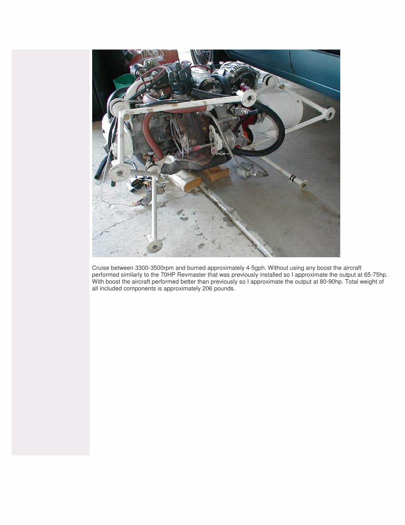
Cruise between 3300-3500rpm and burned approximately 4-5gph. Without using any boost the aircraft performed similarly to the 70HP Revmaster that was previously installed so I approximate the output at 65-75hp. With boost the aircraft performed better than previously so I approximate the output at 80-90hp. Total weight of all included components is approximately 206 pounds.
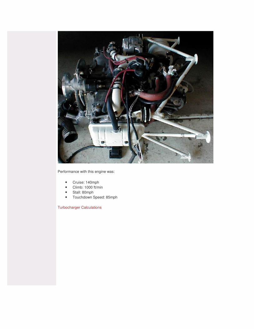
Performance with this engine was:
• Cruise: 140mph • Climb: 1000 ft/min • Stall: 80mph • Touchdown Speed: 85mph
Turbocharger Calculations

The following images were drawn by an engineer who used an EA-81DDT on his airplane. The prop hub & flywheel that I built were based on these drawings and were very similar. I believe the only change was to the flywheel diameter so it would match the ring gear that I selected. EA-81 DDT Flywheel

EA-81 DDT Prop Hub
© 2004 FinleyWeb.Net. All Rights Reserved.

Q2 - Subaru Q2 Log Subaru EJ-22 Q2 Information Subaru EA-81 DDT Q2-Q200 Video Quickie-Q2 Plans
Miscellaneous For Sale - Misc Tools Subaru Documentation
Aviation Links Quickie Builders Assoc. AOPA EAA Kitplanes Magazine
EA-81 Conversion This is an article that a I wrote for Q-Talk, the Quickie Builders Association newsletter back in 2001. This is simply a "here's what I did" article and is not intended to be instructions or a conversion manual. Jon Finley – N90MG “Subar-Sonic” Q-Baru Conversion March 10, 2001 When I began my conversion my Q2 had 380 hours, T-tail, reflexor, GU canard, an electric T&B, Wellan nav/strobe lights, transponder, single nav/com, Revmaster 2100DQ w/75HP heads, and weighed 640 lbs. In my opinion, it was underpowered. I did not care for the Revmaster and decided to replace it. My conversion objective was to find an affordable power plant than I trusted. My few design goals included the ability to fly high (15,000), good cruise/climb performance (165 mph (at altitude), 1500 ft/min), and low cost. Obviously these are pretty easy objectives to reach with a Q-200, however; the cost requirement ruled out an O-200. I had been following the Subaru movement for a number of years and really liked what I had observed. I lived in the same city as Bud Clark (Helena, MT) during the first half of the 90’s. This mad it easy for me to follow the work that the Clark brothers were undertaking with their direct drive Subaru powered Dragonfly’s. I found that the direct drive Subaru EA-81s had been serving the gyrocopter group very reliably for many years. I am told that an engine experiences much higher gyroscopic propeller loads on a gyrocopter than a typical aircraft will ever experience and there had not been any reports of crankshaft problems on the direct-drive gyrocopters. The final straw was meeting Roger Enns. Roger was flying an EA-81 direct drive turbo, similar to Reg Clarks setup. Roger was an engineer with Orenda, was very pleased with his Subaru conversion, and was willing to help me with the conversion. I do not think I could have ever got through the process without Roger and owe him a huge debt for all his assistance. The EA-81 is an 1800cc horizontally opposed four-cylinder engine. This engine is a single cam engine with pushrod actuated overhead valves and comes with either solid or hydraulic lifters. The American engines have a book output of 73hp, the Japanese engines (dual carb, different cam, larger valves) book output is near 100hp. The engine is typically used in aviation with a propeller speed reduction unit (PSRU) to allow the engine to operate in the 5000-6000 rpm range and produce in excess of 100 hp (I believe NSI markets theirs as 120hp). In the direct drive turbo configuration the engine typically operates in the 3200-4000 rpm range and can be expected to produce 80-90 hp (possibly more). My typical cruise rpm is 3400-3500. These engines were available in the 1983-1985 model vehicles with several variations (turbo, carb, solid/hydraulic lifters, etc…). In 1996 I purchased a 1984 Subaru GL wagon with 120,000 miles. The engine had been rebuilt 20,000 miles previous and was the EA-81 1800cc pushrod engine with solid lifters that I wanted to use in my Q2. Sadly, in 1997 the clutch in this car died. It was a difficult decision, but with my wife’s help I decided that I should remove the engine, junk the car, and begin converting the engine for use in my Q2. The engine is completely stock internally - I did not change a single item. Many people are using aftermarket cams and raising the compression ratio to increase horsepower. The following outlines the changes that I made to the engine.
1. Trim bellhousing. 2. Trim oil dipstick and guide. 3. Drill and tap 3/8” NPT hole in case for turbo oil return. Hole is located to left of the oil pump and just
above the oil pan. 4. Drill and tap coolant drain holes in both heads to .25 in. NPT. One port provides coolant to the turbo the

other port is plugged. 5. File lips around the two aft cylinder head attach bolts. This is done to avoid interference with the motor
mount. 6. Weld a piece of steel tubing to the oil pan and tap to 1/8 in. NPT for oil temperature sender. 7. Machine power steering pulley from water pump pulley. 8. Drill and tap end of crankshaft for prop hub safety bolt.
Motor Mount
The motor mount is comprised of five separate pieces. Two lower pieces bolt to the automotive motor mount location on the bottom of the engine. Two upper pieces bolt to two head bolts. These four pieces then bolt to the tube structure that attaches to the firewall. Rubber vibration dampers are installed between the tube structure and four mounting tabs. The mounting tabs were constructed of 1/8” stainless steel. The tube structure is constructed of 4130 tubing - 5/8” diameter with .065” wall. Several other builders are using these same materials without problems so I elected to follow their lead rather than design something new. I used flat rubber vibration dampers from McMaster-Carr. I do not think they do much for vibration isolation and would recommend using a more typical approach.
Intake Manifold
The intake manifold is comprised of three pieces. An aluminum runner connects the carburetor to the turbo. This runner is bolted to the carburetor and to the turbo via flanges. A steel, Y shaped runner connects the turbo to the heads. The connection from turbo to runner uses a rubber hose. The runner is bolted to the intake port on the head. The runner is cut into two pieces and connected with a rubber hose to allow expansion and contraction of the engine. The aluminum runner was constructed from 1.5” aluminum and is V shaped (due to twin barrels of the Weber Carburetor). The runner from turbo to engine is constructed of 1.5” mild steel tubing with .050” wall. The engine is designed for hot coolant to flow out the engine through the intake manifold (keeping it warm). I chose to build the intake flanges out of 1/8” 4130 steel. Each flange has the intake runner and a 5/8” O.D. tube (for the coolant to flow through) welded to it.
Exhaust System
1 5/8” mild steel tubing with .050” wall thickness from JC Whitney was used to fabricate the exhaust. It wraps around the back of the oil pan, joins into a larger, 1.75” tube and then enters the turbo. From the turbo, the exhaust flows through a 2” mild steel tube and is vented overboard on the bottom left side. A muffler is not used. The engine is relatively quite but installation of a muffler would serve to make for a very quite airplane. I intend to pursue this at a later date. The flanges for the head exhaust outlet and turbo inlet were fabricated using 1/8” 4130 plate.
Turbocharger
The turbocharger is from a 1988 EA-82 engine (model years 1985-1988). This turbo includes a water-cooled housing instead of an oil-cooled housing like the EA-81 turbocharged engines. The standard banjo fittings were utilized for all oil and coolant lines. A hole was drilled and tapped in the case just above the oil pan for oil return from the turbo. A braided steel hose is utilized to supply oil to the turbo. An aluminum manifold was fabricated to allow adapting an oil pressure sender to this oil supply line. This turbocharger includes an automatic wastegate limiting manifold pressure to approximately 7.5 psi. This means that this turbocharger/wastegate combination will provide seal level pressure at altitudes greater than 20,000 ft. The disadvantage of retaining the stock system is that the in part throttle conditions, the turbo may be

working only to restore pressure lost due to the pressure drop across the partially closed throttle. Ideally, the turbocharger should only be employed after wide-open throttle has been reached. I decided to operate the wastegate manually to avoid making the turbo work at partial throttle settings. This requires great caution on my part as I am the only pressure control and the wastegate is rather sensitive. A better, although more complex, system would be to incorporate the automatic wastegate into the manual control system. In this fashion, over boost protection and manual control would both exist. In the automotive application this turbo is used with a fuel injection system that does not see high manifold vacuum. Due to this a carbon oil seal is required to prevent the turbo from sucking oil through the seal at high manifold vacuum. To date, I have limited myself to 7 psi of boost.
Ignition
I required a redundant ignition system. There are many variations of redundant systems and each has its own positives and negatives. I feel that the system I settled on meets my requirements for redundancy without adding complexity or expense. The stock distributor is utilized. Within the distributor, there are two Subaru pickup modules. These modules are mounted 180 degrees apart to a new internal mounting plate. Each pickup is wired to a GM electronic control module (NAPA part #TP45) mounted on the firewall. Each control module is wired to a GM coil (NAPA part #IC107). The high-tension outputs from the coils are connected to an MSD “Dual Coil Selector”. The “Coil Selector” takes two high-tension inputs and supplies a single high-tension output. The vacuum advance system was removed and the rotating plate within the distributor removed. The standard mechanical advance system was retained. It provides a total of 20 crankshaft degrees of advance. I initially selected 25 degrees BTDC as my full advance position. I have since changed to 28 degrees BTDC. The primary ignition and fuel pump are powered from the main bus. The secondary ignition and fuel pump are powered directly off the alternator through a capacitor that is responsible for keeping the alternator excited should the battery/main bus fail.
Charging System
A Nippondenso 45 amp alternator was selected due to it's small size and weight (7 lbs). It has an internal voltage regulator. Mounting brackets were fabricated using 3/8” aluminum angle. I machined the second (power steering) pulley off to reduce weight. The alternator electrical connection plug is special so get the matching plug if you get one of these alternators from a wrecking yard. To add redundancy to the electrical system I installed a large capacitor connected across the field wire. Once the engine has been started and the alternator is generating power the battery can be removed and the alternator continues generating power. This system has been verified on the ground.
Motor Mount
The motor mount is comprised of five separate pieces. Two lower pieces bolt to the automotive motor mount location on the bottom of the engine. Two upper pieces bolt to two head bolts. These four pieces then bolt to the tube structure that attaches to the firewall. Rubber vibration dampers are installed between the tube structure and four mounting tabs. The mounting tabs were constructed of 1/8” stainless steel. The tube structure is constructed of 4130 tubing - 5/8” diameter with .065” wall. Several other builders are using these same materials without problems so I elected to follow their lead rather than design something new. I used flat rubber vibration dampers from McMaster-Carr. I do not think they do much for vibration isolation and would recommend using a more typical approach.
Intake Manifold
The intake manifold is comprised of three pieces. An aluminum runner connects the carburetor to the turbo. This runner is bolted to the carburetor and to the turbo via flanges. A steel, Y shaped runner connects the turbo to the heads. The connection from turbo to runner uses a rubber hose. The runner is bolted to the intake port on the head. The runner is cut into two pieces and connected with a rubber hose to allow expansion and contraction of the engine. The aluminum runner was constructed from 1.5” aluminum and is V shaped (due to twin barrels of the Weber Carburetor). The runner from turbo to engine is constructed of 1.5” mild steel tubing with .050” wall. The engine is designed for hot coolant to flow out the engine through the intake manifold (keeping it warm). I chose to build the intake flanges out of 1/8” 4130 steel. Each flange has the intake runner and a 5/8” O.D. tube (for the coolant to flow through) welded to it.
Exhaust System
1 5/8” mild steel tubing with .050” wall thickness from JC Whitney was used to fabricate the exhaust. It wraps around the back of the oil pan, joins into a larger, 1.75” tube and then enters the turbo. From the turbo, the exhaust flows through a 2” mild steel tube and is vented overboard on the bottom left side. A muffler is not used. The engine is relatively quite but installation of a muffler would serve to make for a very quite airplane. I intend to pursue this at a later date. The flanges for the head exhaust outlet and turbo inlet were fabricated using 1/8” 4130 plate.
Turbocharger
The turbocharger is from a 1988 EA-82 engine (model years 1985-1988). This turbo includes a water-cooled housing instead of an oil-cooled housing like the EA-81 turbocharged engines. The standard banjo fittings were utilized for all oil and coolant lines. A hole was drilled and tapped in the case just above the oil pan for oil return from the turbo. A braided steel hose is utilized to supply oil to the turbo. An aluminum manifold was fabricated to allow adapting an oil pressure sender to this oil supply line. This turbocharger includes an automatic wastegate limiting manifold pressure to approximately 7.5 psi. This means that this turbocharger/wastegate combination will provide seal level pressure at altitudes greater than 20,000 ft. The disadvantage of retaining the stock system is that the in part throttle conditions, the turbo may be working only to restore pressure lost due to the pressure drop across the partially closed throttle. Ideally, the turbocharger should only be employed after wide-open throttle has been reached. I decided to operate the wastegate manually to avoid making the turbo work at partial throttle settings. This requires great caution on my part as I am the only pressure control and the wastegate is rather sensitive. A better, although more complex, system would be to incorporate the automatic wastegate into the manual control system. In this fashion, over boost protection and manual control would both exist. In the automotive application this turbo is used with a fuel injection system that does not see high manifold vacuum. Due to this a carbon oil seal is required to prevent the turbo from sucking oil through the seal at high manifold vacuum. To date, I have limited myself to 7 psi of boost.
Ignition
I required a redundant ignition system. There are many variations of redundant systems and each has its own positives and negatives. I feel that the system I settled on meets my requirements for redundancy without adding complexity or expense. The stock distributor is utilized. Within the distributor, there are two Subaru pickup modules. These modules are mounted 180 degrees apart to a new internal mounting plate. Each pickup is wired to a GM electronic control

module (NAPA part #TP45) mounted on the firewall. Each control module is wired to a GM coil (NAPA part #IC107). The high-tension outputs from the coils are connected to an MSD “Dual Coil Selector”. The “Coil Selector” takes two high-tension inputs and supplies a single high-tension output. The vacuum advance system was removed and the rotating plate within the distributor removed. The standard mechanical advance system was retained. It provides a total of 20 crankshaft degrees of advance. I initially selected 25 degrees BTDC as my full advance position. I have since changed to 28 degrees BTDC. The primary ignition and fuel pump are powered from the main bus. The secondary ignition and fuel pump are powered directly off the alternator through a capacitor that is responsible for keeping the alternator excited should the battery/main bus fail.
Charging System
A Nippondenso 45 amp alternator was selected due to its small size and weight (7 lbs). It has an internal voltage regulator. Mounting brackets were fabricated using 3/8” aluminum angle. I machined the second (power steering) pulley off to reduce weight. The alternator electrical connection plug is special so get the matching plug if you get one of these alternators from a wrecking yard. To add redundancy to the electrical system I installed a large capacitor connected across the field wire. Once the engine has been started and the alternator is generating power the battery can be removed and the alternator continues generating power. This system has been verified on the ground.
Fuel System
Due to the location of the carburetor, it is not possible to use a gravity feed fuel system. This being the case, I decided that it did not make much sense to pump fuel to the header tank and then pump fuel from the header to the engine. In my opinion, this was wasted effort and a less than ideal situation. If the fuel pump to the header ever failed I would be left with only 3-4 gallons of fuel available while sitting on many unusable gallons. One possible solution would be to install dual fuel pumps to pump from the main to header and then dual pumps to pump from header to engine. This seemed silly to me. I finally decided to use the header as an auxiliary tank and pump fuel only from the main tank. Dual fuel pumps have been installed and fuel is gravity drained to the main tank when needed. The header tank is filled by changing the position of the fuel valve and turning on one of the fuel pumps. This can only be done on the ground with the engine stopped as the fuel flow is redirected from engine to header tank. The main fuel feed is from the largest source of fuel and the feed of fuel from the header is a very simple gravity feed system. Currently I am running to Facet 3.5psi pumps in series. At the time of installation I understood that the Facet pumps could not fail “closed” (shutting off fuel flow). I have since seen reports indicating that they can and plan to change to a parallel configuration with check valves. I plan to investigate installing a second pickup point in the main tank to have further redundancy.
Cooling System
A radiator from a 1979 VW Rabbit was used. It is mounted about five feet aft of the firewall on the bottom of the fuselage. The forward edge of the radiator is directly under the seatback bulkhead. It is mounted lengthwise using .050” aluminum. The forward edge is mounted 3.5” below the fuselage and the aft end is mounted flush with the fuselage forming a scoop. The coolant flows through 1” x .035 aluminum tubing along the bottom of the fuselage. A swirl pot was fabricated using a length of 4” aluminum tubing. The ends capped and welded, a radiator cap fitting welded to the top, and inlet and outlet fittings welded to the sides. The idea of a swirl pot is to direct the inlet ports at an angle to induce a swirling action inside the pot. The outlet is located at the bottom of the pot at an angle to encourage the coolant to flow out of the pot and into the port. The swirling action is supposed to cause air to separate and move to the top. This air is forced out of the system into a catch tank.
The stock intake manifold, that I did not use, incorporates the coolant thermostat. I elected to use an in-line coolant thermostat from a 1978-1980 Subaru Justy. A BMW unit was initially used. This unit was ideal as it positively shut off the by-pass line when the thermostat was open. However; I was only able to get this unit with a 210-degree thermostat, which is quite high for the Subaru. The current unit contains a 180-degree thermostat. Standard automotive radiator hoses were used. The clerks thought I was crazy when I asked if I could dig through their hoses until I found the shapes that I was looking for! I studied all of radiator/cooling theory documentation that I could find. The obvious problem with applying the principles from these articles is the lack of physical space. They all call for a substantial length to slow the airflow and recover pressure before the radiator and an equally long distance to accelerate the heated air. The Q2 cowling simply does not have enough space for an ideal arrangement. I initially installed a Saturn auto radiator in the cowling using a large NACA duct on the cowling bottom for air. This approach worked in the cool fall/winter temperatures but I was sure that it would not be acceptable during hot outside temps. I modified the cowling in an attempt to get more air to the radiator before admitting defeat and locating the VW radiator on the belly. There are much more ideal radiator installation practices that will be explored as time permits. The current location cools very well but is obviously quite draggy. As time permits, I plan to research installing the radiator in the fuselage, aft of the split line, pulling air in from the bottom of the fuselage and exiting on the top. This is the only arrangement that I can image that may come close to following the pressure recovery theories. For now, I am happy to fly. Two additional approaches that I plan to research include a custom radiator fit in the cowl and a custom radiator fit on the belly with a nice tunnel/scoop arrangement. I believe a very thick (four inches or so) radiator appropriately sized could work in the cowl. The limiting factor to trying either of these approaches is the cost of the radiator.
Instrumentation
The following engine instrumentation was installed:
• Oil Pressure • Oil Temperature • Low Oil Pressure Warning Light • Water Pressure • Water Temperature • Tachometer • Manifold Pressure/Boost • Exhaust Gas Temperature • Amperage • High/Low Voltage Warning Circuit
Starting System
A Valeo starter from a Saturn automobile was utilized due to its small size and weight (7 lbs). The starter was mounted to a ¼” aluminum plate which was bolted through the bellhousing into the block. Currently the starter is oriented such that a small bump is required on the top of the cowling. I have modified another Valeo starter to mount such that the bump will not be required. This was done by removing the mounting tabs from the starter and welding on new tabs at the “correct” location. I plan to install this modified starter sometime this winter.
Flywheel and Prop Hub
The flywheel was machined from a 10.5” x 1” square hunk of aluminum. The flywheel bolts to the crankshaft using the eight bolts that normally attach the stock flywheel. The crankshaft is drilled and tapped and a large bolt inserted through the flywheel and into the crankshaft. A starter ring was liberated from a 1988 Ford Taurus. The ring gear machined off and shrunk fit onto the flywheel. The flywheel is solid aluminum. I now wish now that I drilled lightening holes in the flywheel. It is a relatively heavy part, the next time it is off for maintenance I plan to
drill five or six very large holes (2” possibly) to reduce the total weight. The prop hub was machined from a 6” x 4” hunk of aluminum. The hub has a diameter of 6” at the flywheel end and 5.5” at the prop end. The hub bolts to the flywheel and prop using six 3/8” bolts. The standard Continental prop flange bolt pattern is used.
Weight
My Q2 weighed 640 lbs empty with the Revmaster. With the Subaru, it weighs 672 lbs including oil and coolant. This includes the addition of an auxiliary fuel pump, additional gauges, electrical system changes, 45 amp alternator, turbocharger, three-bladed Warp Drive carbon fiber propeller (replacing the kit two-bladed Cowley wood propeller), and extensive cowling modifications (which have resulted in a very heavy cowling).
Testing
I have performed several engine swaps and am adamant that the engine/airframe work properly on the ground before flight is considered. This includes cooling. I have head many builders state, “it won’t cool on the ground but maybe in-flight there will be enough airflow for it to cool.” I feel that this is a great way to die. Since I have no desire to die, I ran the engine many, many hours on the ground. All sorts of runs were performed, everything from long idle sessions to long high power runs (tied down). When I finally began flying I restricted my flights to orbiting the airport. We are a little jammed into the Class B Minneapolis airspace so I could only go up to 1500’ AGL for my orbits. I spent about six hours over the airport before venturing away from the airport.
Operation
I typically take off at full throttle with the wastegate open. Due to the configuration of the turbocharger and wastegate, this setting yields about 3” of boost. I normally see about 3200 rpm during initial climb. I maintain these settings for the first few thousand feet or until I am out of the airport area. As altitude increases, the amount of boost decreases, at 4000’-5000’ MSL the boost has dropped to about zero (normalized). When additional performance is desired the wastegate can be closed to achieve the desire level of boost. However, I found the additional workload that this introduces to be a safety issue. It is far too much work to manually control the boost level (there is a lag and then it changes VERY quickly) and do all the other things required. Typical cruise rpm is 3400-3500 rpm. The addition of boost during any phase of flight is quite noticeable. A high priority task is to create a mechanism to allow control of the boost level AND utilize overboost protection. This setup will allow the use of maximum boost during takeoff/climb without increasing pilot workload.
Performance
I am still working on propeller tuning. I initially flew with 11.5 degrees of propeller pitch. While climb performance was exceptional, cruise speed was very poor. I next tried 12.5 degrees, this was too much pitch as climb suffered considerably. I then tried 11.75 degrees and have since changed to 12.25 degrees. With each flight I become more familiar with the engine and turbo and am better able to use the power. Obviously there are a number of linked factors that affect this effort and I expect to make steady gains as I learn how to use the turbo and engine. I still don’t have accurate numbers but will report them in the future. On my most recent flights I have been cruising at approximately 140 MPH IAS and showing about 150 MPH TAS.
Impressions
I have noticed that the three-bladed prop seems to produce considerably more drag than the two-blade wood prop during landing. I previously used my speed brake to reduce float and ground roll. Now, I find that I do not experience much float and believe the difference is the drag generated by the prop.

I am pleased with the smoothness of the Subaru. When I relocated the radiator to the belly I noticed a new “rough” sensation. I think the air hitting the radiator is very turbulent. Hopefully, the proper ducting of the radiator will eliminate this sensation. I thought my research had uncovered the details of operating a turbocharged engine. Only now, after operating one, can I appreciate the complexity that the turbocharger adds. I am of the opinion that a turbocharged engine should use computer controlled fuel injection and ignition timing. The additional fuel requirements when operating under boost, the timing changes required when under boost, monitoring of detonation, and control of the wastegate are all extremely difficult to monitor and adjust while flying the airplane. Do to the workload, I find that I am not taking advantage of all the power that the engine is willing to produce for fear of overstressing it or operating it with unsafe parameters. In addition, the turbo runs HOT-HOT-HOT (hotter than I realized). You must plan ahead for this fact.
Modifications
The following list represents the major changes that I would like to make in the near future:
1. Reduce cowling size. The bottom extension was added to enclose the radiator. Now that the radiator has been moved it is empty space. In addition, the amount of cooling air being allowed into the cowl can be reduced significantly.
2. Intercooler. The engine would benefit greatly from a cooler intake air charge. I believe I can reduce the inlet air temp by at least 50 degrees (probably more) with an intercooler. This will yield a corresponding increase in performance while reducing the possibility of detonation. This will add an additional inlet/outlet to the cowl.
3. Turbocharger over-boost protection. I would like to install the OEM wastegate control on a manual control lever such that I can control the boost level and have overboost protection.
4. Radiator fairing/pressure recovery cowling. 5. Knock sensor. 6. Computer controlled fuel injection and ignition control. I am very excited about Tracy Crooks product
(www.rotaryaviation.com) and hope to install it at some point. 7. Aftermarket camshaft. Cams exist that make more power and torque in the rpm range that I am
operating. I am searching for a proven camshaft for the EA-81 direct drive, turbocharged application before committing to this change.
8. Prop tuning. I am told that the Warp Drive is not tailored to high-speed flight. Several people have optimized the WD prop. At some point it would be interesting to pursue this.
I have a long list of fuselage modification that I would like to make. I feel that I have a pretty dirty airplane and think a fair amount of speed can be gained by cleaning up my airframe.
Summary
Would I do it again? Depends what day you ask! Installing a non-standard engine is a tremendous amount of work! There are a lot of Subaru resources available now that did not exist when I started the process. I strongly recommend using these resources. The ability to purchase components will save hundreds of hours and possibly a great deal of frustration. If you really enjoy the building/fabrication process, experimenting, and are going to stick to it - the results are very rewarding. If you are not the mechanical sort and/or just want to fly, install an O-200. If I were to do it again I would use the Subaru EJ-22 Legacy engine. It is 2200cc engine with overhead cams and four-valves per cylinder which produces 140 HP in the car (160 HP turbo). It is a heavier than the EA-81 but produces quite a bit more power. I believe, with close attention to weight savings, a 120 HP direct drive turbo EJ-22 could be built weighing about the same as an O-200 and could cost significantly less. I believe the Subaru engines are very well engineered engines and can be very reliable aircraft engines.
Credits
Roger Enns has been of tremendous help to me throughout this project. He deserves the credit for many of the

ideas that I have implemented and has been a very valuable resource - always willing to help. I appreciate his assistance more than I can state. Reg and Bud Clark were the pioneers. Bud has always been willing to help in any way possible and I appreciate his assistance. If anybody out there is serious about using a Subaru I am happy to help and am available via phone or email. The Subaru Internet mail list is a good source of information. The folks at Air-Ryder (www.air-ryder.com), SubieLyc (www.subielyc.com), Stratus, and RFI ([email protected]) all have parts, plans, and info. .
© 2004 FinleyWeb.Net. All Rights Reserved.