fips non policy systems - csrc · 2.2 cryptographic module ... and generation 4) solutions. the...
TRANSCRIPT

FIPS 140‐2 Non‐Proprietary Security Policy: Persistent Systems Wave Relay Quad Radio Router and Man Portable Unit (Generation 2, Generation 3 Single/Dual, and Generation 4)
Document Version 5.12 © Persistent Systems Page 1 of 25
FIPS 140‐2 Non‐Proprietary Security Policy
Persistent Systems Wave Relay Quad Radio Router and Man Portable Unit (Generation 2, Generation 3 Single/Dual, and Generation 4)
Level 2 Validation
Document Version 5.2
January 8, 2015
Prepared By:
Persistent Systems, LLC 303 Fifth Avenue Suite 207 New York, NY 10016 www.persistentsystems.com

FIPS 140‐2 Non‐Proprietary Security Policy: Persistent Systems Wave Relay Quad Radio Router and Man Portable Unit (Generation 2, Generation 3 Single/Dual, and Generation 4)
Document Version 5.12 © Persistent Systems Page 2 of 25
Abstract This document provides a non‐proprietary FIPS 140‐2 Security Policy for the Wave Relay Quad Radio Router and Man Portable Unit (Generation 2, Generation 3 Single/Dual, and Generation 4).

FIPS 140‐2 Non‐Proprietary Security Policy: Persistent Systems Wave Relay Quad Radio Router and Man Portable Unit (Generation 2, Generation 3 Single/Dual, and Generation 4)
Document Version 5.12 © Persistent Systems Page 3 of 25
TableofContents1 Introduction .............................................................................................................................................. 5
1.1 About FIPS 140 ............................................................................................................................................. 5 1.2 About this Document .................................................................................................................................... 5 1.3 External Resources ....................................................................................................................................... 5 1.4 Notices .......................................................................................................................................................... 5 1.5 Acronyms ...................................................................................................................................................... 5
2 Persistent Systems Wave Relay Quad Radio Router and Man Portable Unit (Generation 2, Generation 3 Single/Dual, and Generation 4) .......................................................................................................................... 7
2.1 Wave Relay Product Overview ..................................................................................................................... 7 2.2 Cryptographic Module Specification ............................................................................................................ 7
2.2.1 Validation Level Detail ............................................................................................................................. 9 2.2.2 Algorithm Implementation Certificates ................................................................................................... 9
2.3 Module Interfaces ...................................................................................................................................... 11 2.4 Roles, Services, and Authentication ........................................................................................................... 12
2.4.1 Operator Services and Descriptions....................................................................................................... 12 2.4.2 Operator Authentication ....................................................................................................................... 13
2.5 Physical Security ......................................................................................................................................... 13 2.6 Operational Environment ........................................................................................................................... 13 2.7 Cryptographic Key Management ............................................................................................................... 13 2.8 Self‐Tests .................................................................................................................................................... 17
2.8.1 Power‐On Self‐Tests .............................................................................................................................. 18 2.8.2 Conditional Self‐Tests ............................................................................................................................ 18
2.9 EMI/EMC .................................................................................................................................................... 19 2.10 Mitigation of Other Attacks ....................................................................................................................... 19
3 Guidance and Secure Operation ................................................................................................................ 20 3.1 Crypto Officer and User Guidance .............................................................................................................. 20
3.1.1 Initialization for FIPS Mode of Operation .............................................................................................. 20 3.1.2 General Crypto Officer and User Guidance ........................................................................................... 20 3.1.3 Tamper Evidence ................................................................................................................................... 20

FIPS 140‐2 Non‐Proprietary Security Policy: Persistent Systems Wave Relay Quad Radio Router and Man Portable Unit (Generation 2, Generation 3 Single/Dual, and Generation 4)
Document Version 5.12 © Persistent Systems Page 4 of 25
ListofTables
Table 1 – Acronyms and Terms ...................................................................................................................................... 6
Table 2 – Validation Level by DTR Section ..................................................................................................................... 9
Table 3 – Algorithm Certificates for Wave Relay Hardware Implementation ............................................................... 9
Table 4 – Algorithm Certificates for Wave Relay Firmware Implementation .............................................................. 10
Table 5 – Cryptographic Functions Disallowed per NIST SP 800‐131A Algorithm Transitions ................................. 10
Table 5 – Logical Interface / Physical Interface Mapping ............................................................................................ 11
Table 6 – Operator Services and Descriptions ............................................................................................................. 12
Table 7 – Key/CSP Management Details (also includes public keys) ........................................................................... 17
ListofFigures
Figure 1 – Physical Boundary of MPU2 (top left), MPU3S (bottom left). MPU3D (bottom center), MPU4 (bottom right), and QRS (top right) .................................................................................................................................... 8
Figure 2 – Tamper‐evident material placement for MPU Top (2 locations indicated by red circles) .......................... 21
Figure 3 – Tamper‐evident material placement for MPU Bottom (2 locations indicated by red circles) .................... 22
Figure 4 – Tamper‐evident material placement for MPU3 (4 locations indicated by red circles) ............................... 22
Figure 5 ‐ Tamper‐evident material placement for MPU4 (4 locations indicated by red arrows) .............................. 23
Figure 6 – Tamper‐evident material placement for Quad Radio Router Cover (4 locations indicated by red circles) 24
Figure 7 – Tamper‐evident material placement for Quad Radio Router Wireless Radio Port (Top – 2 locations indicated by the red circle) ................................................................................................................................ 24
Figure 8 – Tamper‐evident material placement for Quad Radio Router Bottom (9 locations indicated by the red circle) .................................................................................................................................................................. 25
Figure 9 – Tamper‐evident material placement for Quad Radio Router Serial Port (Left – 2 locations indicated by the red circle) ..................................................................................................................................................... 25

FIPS 140‐2 Non‐Proprietary Security Policy: Persistent Systems Wave Relay Quad Radio Router and Man Portable Unit (Generation 2, Generation 3 Single/Dual, and Generation 4)
Document Version 5.12 © Persistent Systems Page 5 of 25
1 Introduction
1.1 AboutFIPS140
Federal Information Processing Standards Publication 140‐2 — Security Requirements for Cryptographic Modules specifies requirements for cryptographic products to be deployed in a Sensitive but Unclassified environment. The National Institute of Standards and Technology (NIST) and Communications Security Establishment Canada (CSEC) Cryptographic Module Validation Program (CMVP) owns the FIPS 140 program. The CMVP accredits independent testing labs to perform FIPS 140 testing; the CMVP also validates test reports for all products pursuing FIPS 140 validation. Validation is the term given to a product that is documented and tested against the FIPS 140 criteria.
More information is available on the CMVP website at http://csrc.nist.gov/groups/STM/cmvp/index.html.
1.2 AboutthisDocument
This non‐proprietary Cryptographic Module Security Policy for the Wave Relay Quad Radio Router and Man Portable Unit (Generation 2, Generation 3 Single/Dual, and Generation 4) from Persistent Systems provides an overview of the products and a high‐level description of how they meet the security requirements of FIPS 140‐2. This document contains details on the modules’ cryptographic keys and critical security parameters. This Security Policy concludes with instructions and guidance on running the modules in a FIPS 140‐2 mode of operation.
The Persistent Systems Wave Relay Quad Radio Router and Man Portable Unit (Generation 2, Generation 3 Single/Dual, and Generation 4) may also be referred to as the “modules” in this document.
1.3 ExternalResources
The Persistent Systems website (http://www.persistentsystems.com) contains information on the full line of products from Persistent Systems, including a detailed overview of the Wave Relay Quad Radio Router and Man Portable Unit (Generation 2, Generation 3 Single/Dual, and Generation 4) solutions. The Cryptographic Module Validation Program website (http://csrc.nist.gov/groups/STM/cmvp/) contains links to the FIPS 140‐2 certificate and Persistent Systems contact information.
1.4 Notices
This document may be freely reproduced and distributed in its entirety without modification.
1.5 Acronyms
The following table defines acronyms found in this document:
Acronym Term
AES Advanced Encryption Standard

FIPS 140‐2 Non‐Proprietary Security Policy: Persistent Systems Wave Relay Quad Radio Router and Man Portable Unit (Generation 2, Generation 3 Single/Dual, and Generation 4)
Document Version 5.12 © Persistent Systems Page 6 of 25
Acronym Term
CSEC Communications Security Establishment Canada
CSP Critical Security Parameter
DTR Derived Testing Requirement
FIPS Federal Information Processing Standard
GUI Graphical User Interface
HMAC Keyed‐Hash Message Authentication Code
KAT Known Answer Test
MAN Mobile Ad‐hoc Network
MPU Man Portable Unit
NIST National Institute of Standards and Technology
SHA Secure Hashing Algorithm Table 1 – Acronyms and Terms

FIPS 140‐2 Non‐Proprietary Security Policy: Persistent Systems Wave Relay Quad Radio Router and Man Portable Unit (Generation 2, Generation 3 Single/Dual, and Generation 4)
Document Version 5.12 © Persistent Systems Page 7 of 25
2 PersistentSystemsWaveRelayQuadRadioRouterandManPortableUnit(Generation2,Generation3Single/Dual,andGeneration4)
2.1 WaveRelayProductOverview
The Wave Relay™ solution provides a scalable high performance solution for deploying large Mesh or MANET systems. The Quad Radio router can contain up to 4 separate wireless radios all of which both participate in the routing and can provide connectivity to 802.11 based wireless clients. By utilizing 4 radios, the Wave Relay™ router can simultaneously provide a multi‐channel high speed multi‐hop backhaul and provide client connectivity to client devices. This provides a single solution to all of your mesh networking needs. Wave Relay™ provides a unique combination of deployment flexibility, dynamic self configuring routing, throughput optimized route selection, fault tolerance, and scalability.
The Wave Relay™ Mobile Ad Hoc Networking System is available in a Man Portable form factor, providing a wearable wireless connectivity solution for users on the move. The Wave Relay™ Man Portable Unit is delivers mobility while providing high communication performance. Designed specifically for military and public safety first responders, the Man Portable Unit (MPU) enables mobile users to establish and to maintain a high‐speed wireless data network without relying on any existing fixed infrastructure.
2.2 CryptographicModuleSpecification
The modules are the Persistent Systems
Wave Relay Man Portable Unit Generation 2 HW P/N MPU2 Version 3.0 and 3.1
Wave Relay Man Portable Unit Generation 3 Single HW P/N MPU3S Version 1.0, 1.1, 1.2, 1.3, 1.4, 1.4.1, 1.5, 2, and 3
Wave Relay Man Portable Unit Generation 3 Dual HW P/N MPU3D Version 1.0, 1.1, 1.2, 1.3, 1.4, 1.5, 2, 3 and 4
Wave Relay Man Portable Unit Generation 4 HW P/N MPU4 Version 1.0, 1.0.1, 1.1, 1.2, 1.3, 2, 3, and 4
Wave Relay Quad Radio Router HW P/N QRS, Version 2.1, 2.2, 2.3, and 3
All modules use FW Version 17.3.42, 17.3.46, 18.0.10, 18.0.25, 18.1.9, 18.2.1, 18.3.1, 18.4.2, 18.5.2, or 18.5.3. Each module is a multiple‐chip standalone embodiment.
For the MPU3S, MPU3D, MPU4, and QRS, the physical cryptographic boundary is defined as the module case, which includes the Wave Relay main board, including the hardware cryptographic accelerator chip, drivers, CPU, and on‐board flash memory. The boundary does not include any port caps.
For the MPU2, the physical cryptographic boundary is defined as the module case, which is the same for both versions of the module. The boundary includes the Wave Relay main board, which includes the hardware cryptographic accelerator chip, drivers, CPU, and on‐board flash memory. The boundary does not include the module dust caps and battery caps. Additionally, the 3 dimensional space in which the batteries reside is not part of the boundary; the boundary is defined at the contact points for the batteries within the battery location.

FIPS 140‐2 Non‐Proprietary Security Policy: Persistent Systems Wave Relay Quad Radio Router and Man Portable Unit (Generation 2, Generation 3 Single/Dual, and Generation 4)
Document Version 5.12 © Persistent Systems Page 8 of 25
Figure 1 – Physical Boundary of MPU2 (top left), MPU3S (bottom left). MPU3D (bottom center), MPU4 (bottom right), and QRS (top right)
The tamper evident seals and tamper evident material shall be applied to the module to operate in a FIPS Approved mode of operation.
The following components are excluded from the cryptographic modules:
Radio card(s) resident in the module case o These components do not provide any approved cryptographic services. A radio card
performs RF conversion for the packets sent/received via a Wireless Radio Port, which is within the boundary and is included in the module.
The modules are in FIPS‐approved mode of operation when the validated firmware is used and when only Approved/allowed functionality is used. They do not have any bypass capability.

FIPS 140‐2 Non‐Proprietary Security Policy: Persistent Systems Wave Relay Quad Radio Router and Man Portable Unit (Generation 2, Generation 3 Single/Dual, and Generation 4)
Document Version 5.12 © Persistent Systems Page 9 of 25
2.2.1 ValidationLevelDetail
The following table lists the level of validation for each area in FIPS 140‐2:
FIPS 140‐2 Section Title Validation Level
Cryptographic Module Specification 3
Cryptographic Module Ports and Interfaces 2
Roles, Services, and Authentication 2
Finite State Model 2*
Physical Security 2
Operational Environment N/A
Cryptographic Key Management 2
Electromagnetic Interference / Electromagnetic Compatibility
2
Self‐Tests 2*
Design Assurance 3
Mitigation of Other Attacks N/A
Overall Level 2 Table 2 – Validation Level by DTR Section*
2.2.2 AlgorithmImplementationCertificates
The modules’ cryptographic algorithm implementations have received the following certificate numbers from the Cryptographic Algorithm Validation Program:
Algorithm Type
Algorithm Standard CAVP Cert.
Use
Hashing SHA‐1, SHA‐2: SHA‐224, SHA‐256, SHA‐384, SHA‐512
FIPS 180‐3 1140 Message digest
Keyed Hash HMAC‐SHA1, HMAC‐SHA‐224, HMAC‐SHA256, HMAC‐SHA384, HMAC‐SHA512
FIPS 198 725 Message integrity, module integrity
Symmetric Key
AES CTR, ECB, CBC, GCM mode with 128, 192, or 256‐bit keys
FIPS 197 1241 Data encryption / decryption
Table 3 – Algorithm Certificates for Wave Relay Hardware Implementation
Algorithm Type
Algorithm Standard CAVP Cert.
Use
Asymmetric Key
FIPS 186‐2 DSA: SigVer; 1024 bits (with SHA‐1)
Digital Signature Standard
409 Signature verification
FIPS 186‐2 RSA: KeyGen: 2048, 3072, 4096 bits SigGen: 2048, 3072, 4096 bits (with SHA‐2) SigVer: 1024, 1536, 2048, 3072, 4096 bits (with SHA‐1 or SHA‐2)
PKCS1.5 595 Signature generation and verification, key generation
* The requirements for the sections titled Cryptographic Module Specification, Finite State Model, and Self Tests are the same for all validation levels and by convention are assigned a level equal to the overall level of the module.

FIPS 140‐2 Non‐Proprietary Security Policy: Persistent Systems Wave Relay Quad Radio Router and Man Portable Unit (Generation 2, Generation 3 Single/Dual, and Generation 4)
Document Version 5.12 © Persistent Systems Page 10 of 25
Algorithm Type
Algorithm Standard CAVP Cert.
Use
Hashing SHA‐1 SHA‐2: SHA‐224, SHA‐256, SHA‐384, SHA‐512
FIPS 180‐3 1141 Message digest
Keyed Hash HMAC‐SHA1, HMAC‐SHA‐224, HMAC‐SHA256, HMAC‐SHA384, HMAC‐SHA512
FIPS 198 726 Message integrity
Symmetric Key
AES CBC, ECB, CFB8, CFB128, OFB modes each with 128, 192, or 256 bit keys
FIPS 197 1242 Data encryption / decryption
Triple‐DES ECB, CBC, CFB8, CFB64, OFB FIPS 46‐3 889 Data encryption / decryption
RNG ANSI X9.31 Appendix A.2.4 ANSI X9.31 689 Random Number Generation
Table 4 – Algorithm Certificates for Wave Relay Firmware Implementation
The following non‐approved protocols/algorithms are available in FIPS mode of operation:
RSA within TLS for Key establishment (key wrapping; key establishment methodology provides 112 bits of encryption strength)
Hardware non‐deterministic random number generator (NDRNG) (allowed for seeding FIPS‐approved RNG)
SSH protocol*
802.11 Access Point security: WPA2/WPA/WEP protocols*
MD5 with TLS*
MD5*
* No security is claimed from the use of these protocols/algorithms.
The module supports the following algorithms which are Disallowed as of January 1, 2014 per the NIST SP 800‐131A algorithm transitions:
Algorithm Type
Algorithm Standard CAVP Cert.
Use
Asymmetric Key
FIPS 186‐2 DSA: SigGen: 1024 bits (with SHA‐1) PQGGen: 1024 bits KeyGen: 1024 bits
Digital Signature Standard
409 Signature generation, parameter generation, key generation
FIPS 186‐2 RSA: KeyGen: 1024, 1536 bits SigGen: 1024, 1536 bits (any SHA); 2048, 3072, 4096 bits (SHA‐1)
PKCS1.5 595 Signature generation, key generation
Table 5 – Cryptographic Functions Disallowed per NIST SP 800‐131A Algorithm Transitions
Algorithms providing less than 112 bits of security strength (Disallowed per NIST SP 800‐131A) are not allowed in the FIPS Approved mode of operation for use by Federal agencies. It is the responsibility of the module operator to ensure that algorithms, modes, and key sizes Disallowed per NIST SP 800‐131A are not used.

FIPS 140‐2 Non‐Proprietary Security Policy: Persistent Systems Wave Relay Quad Radio Router and Man Portable Unit (Generation 2, Generation 3 Single/Dual, and Generation 4)
Document Version 5.12 © Persistent Systems Page 11 of 25
2.3 ModuleInterfaces
The interfaces for the cryptographic boundary include physical and logical interfaces. The physical interfaces provided by each module are mapped to four FIPS 140‐2 defined logical interfaces: Data Input, Data Output, Control Input, and Status Output. The mapping of logical interfaces to module physical interfaces is provided in the following table:
FIPS 140‐2 Logical Interface
QRS Module Physical Interface
MPU2 Module Physical Interface
MPU3S Module Physical Interface
MPU3D Module Physical Interface
MPU4 Module Physical Interface
Data Input Ethernet ports (5), Wireless Radio ports (4), GPS antenna port, Serial port
Ethernet port, Wireless Radio port, GPS antenna port
I/O port, Wireless Radio port, GPS antenna port
I/O port, Wireless Radio ports (2), GPS antenna port
I/O port, Wireless Radio port, GPS antenna port, Battery Status port
Data Output Ethernet ports (5), Wireless Radio ports (4), Serial port
Ethernet port, Wireless Radio port
I/O port, Wireless Radio port
I/O port, Wireless Radio ports (2)
I/O port, Wireless Radio port, Battery Status port
Control Input Ethernet ports (5), Wireless Radio ports (4), Serial port, Power/Zero Button
Ethernet port, Wireless Radio port, Power/Zero Button
I/O port, Wireless Radio port, Power/Zero Button
I/O port, Wireless Radio ports (2), Power/Zero Button
I/O port, Wireless Radio port, Power/Zero Button
Status Output Ethernet ports (5), Wireless Radio ports (4), Serial port Status LED
Ethernet port Wireless Radio port, Green LED (unit power on), Red LED (battery power low)
I/O port, Wireless Radio port, Status LED
I/O port, Wireless Radio ports (2), Status LED
I/O port, Wireless Radio port, Status LED
Power Power supply plane
Power supply plane
Power supply plane
Power supply plane
Power supply plane
Table 6 – Logical Interface / Physical Interface Mapping
FIPS 140‐2 Non‐Proprietary Security Policy: Persistent Systems Wave Relay Quad Radio Router and Man Portable Unit (Generation 2, Generation 3 Single/Dual, and Generation 4)
Document Version 5.12 © Persistent Systems Page 12 of 25
2.4 Roles,Services,andAuthentication
Each module only supports a FIPS‐Approved mode. The modules are accessed via Web browser over HTTPS/TLS. As required by FIPS 140‐2, each module supports a Crypto Officer role and a User role. In addition each module supports a Network Management role where an operator indirectly controls the module through another module. The modules support role‐based authentication, and the respective services for each role are described in the following sections.
All three roles can access all services in each module. The modules do not support a Maintenance role. The “Unauthenticated” role indicates services that the modules perform automatically after POST and services that an operator may perform without authentication (e.g. by pressing a button on case).
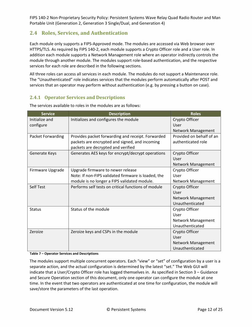
2.4.1 OperatorServicesandDescriptions
The services available to roles in the modules are as follows:
Service Description Roles
Initialize and configure
Initializes and configures the module Crypto Officer User Network Management
Packet Forwarding Provides packet forwarding and receipt. Forwarded packets are encrypted and signed, and incoming packets are decrypted and verified
Provided on behalf of an authenticated role
Generate Keys Generates AES keys for encrypt/decrypt operations Crypto Officer User Network Management
Firmware Upgrade Upgrade firmware to newer release Note: If non‐FIPS validated firmware is loaded, the module is no longer a FIPS validated module.
Crypto Officer User Network Management
Self Test Performs self tests on critical functions of module Crypto Officer User Network Management Unauthenticated
Status Status of the module Crypto Officer User Network Management Unauthenticated
Zeroize Zeroize keys and CSPs in the module Crypto Officer User Network Management Unauthenticated
Table 7 – Operator Services and Descriptions
The modules support multiple concurrent operators. Each “view” or “set” of configuration by a user is a separate action, and the actual configuration is determined by the latest “set.” The Web GUI will indicate that a User/Crypto Officer role has logged themselves in. As specified in Section 3 – Guidance and Secure Operation section of this document, only one operator can configure the module at one time. In the event that two operators are authenticated at one time for configuration, the module will save/store the parameters of the last operation.

FIPS 140‐2 Non‐Proprietary Security Policy: Persistent Systems Wave Relay Quad Radio Router and Man Portable Unit (Generation 2, Generation 3 Single/Dual, and Generation 4)
Document Version 5.12 © Persistent Systems Page 13 of 25
2.4.2 OperatorAuthentication
Crypto Officer and User password must be a minimum of 8 characters (see Section 3 – Guidance and Secure Operation section of this document). The password can consist of alphanumeric values, a-z A-Z 0-9, yielding 62 choices per character. The probability of a successful random attempt is 1/628,
which is less than 1/1,000,000. Assuming 10 attempts per second via a scripted or automatic attack, the probability of a success with multiple attempts in a one‐minute period is 600/628, which is less than 1/100,000.
The Network Management Role authenticates via a MAC on network management packets (listed in Table 8 – Key/CSP Management Details.) The MAC on each packet is 96‐bits and computed with a minimum key size of 256‐bits. The probability of a successful random attempt is 1/296, which is less than 1/7.9e28. Even at maximum theoretical 100 Mbps Ethernet packet rate (around 130,000 packets per second), the probability of a success with multiple attempts in a one‐minute period is 1/1.0e22, which is less than 1/100,000.
2.5 PhysicalSecurity
The physical security of the cryptographic modules meets FIPS 140‐2 Level 2 requirements. Each cryptographic module consists of production‐grade components encased within an opaque and hard production‐grade enclosure that includes standard passivity techniques. The physical boundary of each cryptographic module is the same as the physical boundary of the device. Tamper evidence is provided by the use of a tamper evident colored adhesive covering the module access screws and nuts. Any attempt to remove the cover will leave evidence of tampering.
More details, including proper installation of the tamper‐evident material, can be found in Section 3 – Guidance and Secure Operation of this document.
The modules do not include a maintenance interface; therefore, the FIPS‐140‐2 maintenance mode requirements do not apply.
2.6 OperationalEnvironment
Each module runs in a limited, purpose‐built operational environment. As such, the requirements of this section do not apply.
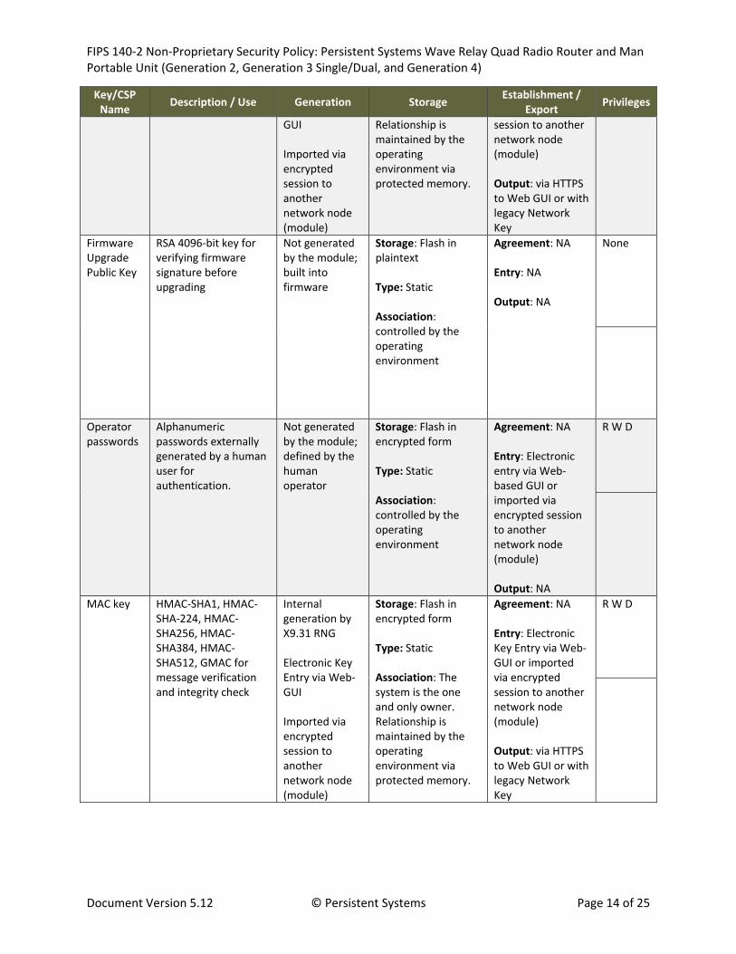
2.7 CryptographicKeyManagement
The table below provides a complete list of Critical Security Parameters and Public Keys used within the modules:
Key/CSP Name
Description / Use Generation Storage Establishment /
Export Privileges
Network Key
AES CTR, CBC, GCM mode with 128, 192, or 256‐bit key for encryption / decryption of network traffic
Internal generation by X9.31 RNG Electronic Key Entry via Web‐
Storage: Flash in encrypted form Association: The system is the one and only owner.
Agreement: NA Entry: Electronic Key Entry via Web‐GUI or imported via encrypted
R W D
FIPS 140‐2 Non‐Proprietary Security Policy: Persistent Systems Wave Relay Quad Radio Router and Man Portable Unit (Generation 2, Generation 3 Single/Dual, and Generation 4)
Document Version 5.12 © Persistent Systems Page 14 of 25
Key/CSP Name
Description / Use Generation Storage Establishment /
Export Privileges
GUI Imported via encrypted session to another network node (module)
Relationship is maintained by the operating environment via protected memory.
session to another network node (module) Output: via HTTPS to Web GUI or with legacy Network Key
Firmware Upgrade Public Key
RSA 4096‐bit key for verifying firmware signature before upgrading
Not generated by the module; built into firmware
Storage: Flash in plaintext Type: Static Association: controlled by the operating environment
Agreement: NA Entry: NA Output: NA
None
Operator passwords
Alphanumeric passwords externally generated by a human user for authentication.
Not generated by the module; defined by the human operator
Storage: Flash in encrypted form Type: Static Association: controlled by the operating environment
Agreement: NA Entry: Electronic entry via Web‐based GUI or imported via encrypted session to another network node (module) Output: NA
R W D
MAC key HMAC‐SHA1, HMAC‐SHA‐224, HMAC‐SHA256, HMAC‐SHA384, HMAC‐SHA512, GMAC for message verification and integrity check
Internal generation by X9.31 RNG Electronic Key Entry via Web‐GUI Imported via encrypted session to another network node (module)
Storage: Flash in encrypted form Type: Static Association: The system is the one and only owner. Relationship is maintained by the operating environment via protected memory.
Agreement: NA Entry: Electronic Key Entry via Web‐GUI or imported via encrypted session to another network node (module) Output: via HTTPS to Web GUI or with legacy Network Key
R W D

FIPS 140‐2 Non‐Proprietary Security Policy: Persistent Systems Wave Relay Quad Radio Router and Man Portable Unit (Generation 2, Generation 3 Single/Dual, and Generation 4)
Document Version 5.12 © Persistent Systems Page 15 of 25
Key/CSP Name
Description / Use Generation Storage Establishment /
Export Privileges
TLS Premaster Secret
RSA‐Encrypted Premaster Secret Message (48 Bytes)
As part of TLS handshake
Storage: RAM in plaintext Type: Ephemeral Association: The system is the one and only owner. Relationship is maintained by the operating system via protected memory.
Agreement: NA Entry: Input during TLS negotiation Output: Output to peer encrypted by Public Key
None
TLS Master Secret
Used for computing the Session Key (48 Bytes)
As part of TLS handshake
Storage: RAM in plaintext Type: Ephemeral Association: The system is the one and only owner. Relationship is maintained by the operating system via protected memory.
Agreement: NA Entry: NA Output: NA
None
RNG XKEY 256‐bit value to key the FIPS‐approved ANSI X9.31 RNG
Hardware NDRNG
Storage: RAM in plaintext Type: Ephemeral Association: The system is the one and only owner. Relationship is maintained by the operating system via protected memory.
Agreement: NA Entry: NA Output: NA
None
RNG XSEED 128‐bit x‐seed Hardware NDRNG
Storage: RAM in plaintext Type: Ephemeral
Agreement: NA Entry: NA Output: NA
None

FIPS 140‐2 Non‐Proprietary Security Policy: Persistent Systems Wave Relay Quad Radio Router and Man Portable Unit (Generation 2, Generation 3 Single/Dual, and Generation 4)
Document Version 5.12 © Persistent Systems Page 16 of 25
Key/CSP Name
Description / Use Generation Storage Establishment /
Export Privileges
Association: The operating environment is the one and only owner. Relationship is maintained by the operating environment via protected memory.
TLS Public Key
RSA Public 2048‐bit for sign / verify operations and key establishment for TLS sessions. Encryption/Decryption of the Premaster Secret for entry/output
Internal generation by X9.31 RNG
Storage: Flash in encrypted form Type: Static Association: The system is the one and only owner. Relationship is maintained by the operating system via X.509 certificates.
Agreement: NA Entry: NA Output: As part of TLS handshake
R W D
TLS Private Key
RSA Private 2048‐bit for sign / verify operations and key establishment1 for TLS sessions
Internal generation by X9.31 RNG
Storage: Flash in encrypted form Type: Static Association: The system is the one and only owner. Relationship is maintained by the operating system via protected memory.
Agreement: NA Entry: NA Output: NA
R W D
Store Key AES CBC 256‐bit key for encryption of Flash data store
Internal generation by X9.31 RNG
Storage: Battery backed RAM in plaintext Type: Static Association: The
Agreement: NA Entry: NA Output: NA
R W D
1 Key establishment methodology provides at least 112‐bits of encryption strength

FIPS 140‐2 Non‐Proprietary Security Policy: Persistent Systems Wave Relay Quad Radio Router and Man Portable Unit (Generation 2, Generation 3 Single/Dual, and Generation 4)
Document Version 5.12 © Persistent Systems Page 17 of 25
Key/CSP Name
Description / Use Generation Storage Establishment /
Export Privileges
system is the one and only owner. Relationship is maintained by the operating environment via protected memory.
TLS Session Keys
AES 256 bit key used with TLS
Generated as part of TLS handshake
Storage: SRAM Type: Ephemeral Association: The system is the one and only owner. Relationship is maintained by the operating environment via protected memory
Agreement: N/A Entry: N/A Output: N/A
None
Table 8 – Key/CSP Management Details (also includes public keys)
R = Read W = Write D = Delete (applies to all roles)
Note that hardware NDRNG entropy source provides 384 bits of entropy to key and seed the RNG. This helps ensure sufficient strength of the seed so as to not compromise the output.
Network Keys can be exported from the physical boundary of the module when the Crypto Officer re‐keys the module using the network management feature. The Network Key will be sent to other nodes (modules) on the network encrypted with the legacy Network Key.
All persistent keys and CSPs are stored in an encrypted store. This store is located in Flash and is encrypted via an AES 256‐bit key. The key & IV used to encrypt the store are stored in battery backed RAM in order to make them persistent. Zeroization has been implemented to ensure no traces are left of the store key & IV. Zeroization is achieved by explicitly overwriting the specific memory area with a constant. Each module can be zeroized by entering a sequence of three short presses on its push button.
2.8 Self‐Tests
Each module includes an array of self‐tests that are run during startup and periodically during operations to prevent secure data from being released and to ensure all components are functioning correctly. In the event of any self‐test failure, the module will output an error and will shutdown. To access status of self‐tests, success or failure, the application provides access to the Web‐based GUI. No keys or CSPs will be output when the module is in an error state.
If the self‐tests succeed, the operator will be presented with a login screen when accessing the module via HTTPS, and attempts to access the module via HTTP will be automatically redirected to HTTPS. If the self‐tests fail, any attempt to access the module via HTTPS will fail because TLS is disabled, and any attempt to access the module via HTTP will result in a FIPS error message.

FIPS 140‐2 Non‐Proprietary Security Policy: Persistent Systems Wave Relay Quad Radio Router and Man Portable Unit (Generation 2, Generation 3 Single/Dual, and Generation 4)
Document Version 5.12 © Persistent Systems Page 18 of 25
Since the modules only support a FIPS‐approved mode of operation the self‐tests are always run. On failure the modules will always be non‐operational as there is no non‐FIPS or bypass mode available.
The following sections discuss the modules’ self‐tests in more detail.
2.8.1 Power‐OnSelf‐Tests
Power‐on self‐tests are run upon every initialization of each module and if any of the tests fail, the process will be halted and the module will not initialize. In this error state, no services can be accessed by the users. The modules implement the following power‐on self‐tests:
Hardware Implementation:
o KAT for AES
o KAT for SHA‐1, SHA‐224, SHA‐256, SHA‐384, SHA‐512
o KAT for HMAC‐SHA1, HMAC‐SHA224, HMAC‐SHA256, HMAC‐SHA384, HMAC‐SHA512
Firmware Implementation:
o Module integrity check via HMAC‐SHA256
o KAT for AES
o KAT for Triple‐DES
o KAT for DSA and RSA
o KAT for RNG
o KAT for HMAC‐SHA1, HMAC‐SHA224, HMAC‐SHA256, HMAC‐SHA384, HMAC‐SHA512
Each module performs all power‐on self‐tests automatically when the module is initialized, and successful running of self tests will be indicated via the GUI. All power‐on self‐tests must be passed before a User/Crypto Officer can perform services. The Power‐on self‐tests can be run on demand by restarting the module.
2.8.2 ConditionalSelf‐Tests
Conditional self‐tests are run continuously when certain conditions are met during operation of each module. The modules perform the following conditional self‐tests:
Pairwise consistency test for RSA
Pairwise consistency test for DSA
Continuous RNG test run on output of ANSI X9.31 RNG implementation
Continuous test to verify that the ANSI X9.31 RNG seed and seed key do not match
Continuous test on RNG seeding mechanism (output of NDRNG)
Firmware load / firmware upgrade test (RSA digital signature verification)
Note that each module performs conditional tests for firmware implementations of the algorithms listed in Table 4 – Algorithm Certificates for Wave Relay Firmware Implementation. The modules’ algorithm implementations in hardware are not required to meet any conditional tests. If any of these tests fail,

FIPS 140‐2 Non‐Proprietary Security Policy: Persistent Systems Wave Relay Quad Radio Router and Man Portable Unit (Generation 2, Generation 3 Single/Dual, and Generation 4)
Document Version 5.12 © Persistent Systems Page 19 of 25
the module will enter an error state. The module can be re‐initialized to clear the error and resume FIPS mode of operation. While in an error state, no services can be accessed by the operators.
2.9 EMI/EMC
Each module meets Federal Communications Commission (FCC) FCC Electromagnetic Interference (EMI) and Electromagnetic Compatibility (EMC) requirements for business use as defined by 47 Code of Federal Regulations, Part 15, Subpart A.
2.10 MitigationofOtherAttacks
The modules do not mitigate other attacks.

FIPS 140‐2 Non‐Proprietary Security Policy: Persistent Systems Wave Relay Quad Radio Router and Man Portable Unit (Generation 2, Generation 3 Single/Dual, and Generation 4)
Document Version 5.12 © Persistent Systems Page 20 of 25
3 GuidanceandSecureOperation
This section describes how to configure each module for FIPS‐approved mode of operation. Operating the module without maintaining the following settings will remove the module from the FIPS‐approved mode of operation.
3.1 CryptoOfficerandUserGuidance
3.1.1 InitializationforFIPSModeofOperation
The Crypto Officer or User must configure and enforce the following procedures:
1. When setting the password, the Crypto Officer or User must ensure that all passwords are a minimum length of 8 characters consisting of the following alphanumeric values: a-z A-Z 0-9 Note: Stronger, more secure passwords should have a combination of letters and numbers and should not contain any recognizable words that may be found in a dictionary. The module does not enforce this; the Crypto Officer or User must follow his/her organization’s systems security policies and adhere to the password policies set forth therein.
2. Ensure FW version running is listed in section 2.2 of this document. 3. Follow Section 3.1.3 – Tamper Evidence 4. After following these steps for the initial configuration for FIPS mode, the Crypto Officer or User
must reboot the module to run the Power On Self Tests prior to operating in a FIPS mode of operation.
3.1.2 GeneralCryptoOfficerandUserGuidance
After initialization for FIPS mode, the Crypto Officer and User should follow the guidance below:
1. When entering a network key over the configuration GUI, the operator must ensure that key was generated by FIPS‐approved methods and that the key was not previously used.
2. The operator must ensure that all Radio MAC addresses used in a network are unique. 3. The Crypto Officer or User must not disclose passwords and must store passwords in a safe
location and according to his/her organization’s systems security policies for password storage. 4. Only the Crypto Officer or User is allowed to remove the case to replace batteries or radio cards.
When the case is removed for these services, the Crypto Officer or User must reapply the tamper‐evidence mechanism as specified in Section 3.1.3 – Tamper Evidence.
5. The SSH service must not be accessed. Using SSH will violate the authorized use policy.
3.1.3 TamperEvidence
Access points to the module case are protected with a tamper‐evident material such that any attempt to remove the case will show signs of tampering. If tampering is demonstrated, the local Crypto Officer is instructed to perform the zeroize operation prior to discarding the module or returning it to the manufacturer.
FIPS 140‐2 Non‐Proprietary Security Policy: Persistent Systems Wave Relay Quad Radio Router and Man Portable Unit (Generation 2, Generation 3 Single/Dual, and Generation 4)
Document Version 5.12 © Persistent Systems Page 21 of 25
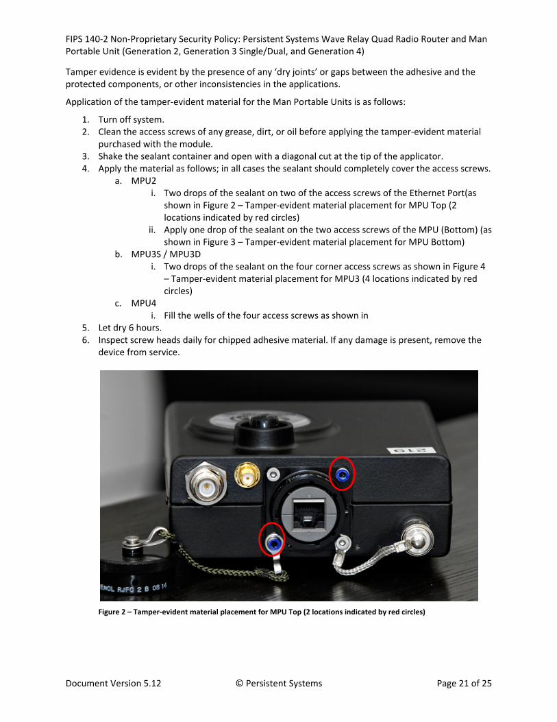
Tamper evidence is evident by the presence of any ‘dry joints’ or gaps between the adhesive and the protected components, or other inconsistencies in the applications.
Application of the tamper‐evident material for the Man Portable Units is as follows:
1. Turn off system. 2. Clean the access screws of any grease, dirt, or oil before applying the tamper‐evident material
purchased with the module. 3. Shake the sealant container and open with a diagonal cut at the tip of the applicator. 4. Apply the material as follows; in all cases the sealant should completely cover the access screws.
a. MPU2 i. Two drops of the sealant on two of the access screws of the Ethernet Port(as
shown in Figure 2 – Tamper‐evident material placement for MPU Top (2 locations indicated by red circles)
ii. Apply one drop of the sealant on the two access screws of the MPU (Bottom) (as shown in Figure 3 – Tamper‐evident material placement for MPU Bottom)
b. MPU3S / MPU3D i. Two drops of the sealant on the four corner access screws as shown in Figure 4
– Tamper‐evident material placement for MPU3 (4 locations indicated by red circles)
c. MPU4 i. Fill the wells of the four access screws as shown in
5. Let dry 6 hours. 6. Inspect screw heads daily for chipped adhesive material. If any damage is present, remove the
device from service.
Figure 2 – Tamper‐evident material placement for MPU Top (2 locations indicated by red circles)

FIPS 140‐2 Non‐Proprietary Security Policy: Persistent Systems Wave Relay Quad Radio Router and Man Portable Unit (Generation 2, Generation 3 Single/Dual, and Generation 4)
Document Version 5.12 © Persistent Systems Page 22 of 25
Figure 3 – Tamper‐evident material placement for MPU Bottom (2 locations indicated by red circles)
Figure 4 – Tamper‐evident material placement for MPU3 (4 locations indicated by red circles)

FIPS 140‐2 Non‐Proprietary Security Policy: Persistent Systems Wave Relay Quad Radio Router and Man Portable Unit (Generation 2, Generation 3 Single/Dual, and Generation 4)
Document Version 5.12 © Persistent Systems Page 23 of 25
Figure 5 ‐ Tamper‐evident material placement for MPU4 (4 locations indicated by red arrows)
Application of the tamper‐evident material for the Quad Radio Router is as follows:
1. Turn off system. 2. Clean the unit of grease, dirt, or oil and make sure unit is dry before applying tamper‐evident
material delivered with the module. 3. Apply the opaque white material to the following locations. Material must contact both the side
of the bolt/connector and the metal enclosure. a. Four locations on the front cover screws as shown in figure 4 b. Two location on the Wireless Radio port on the top of the module as shown in figure 5 c. Nine locations on the bottom removable ports as shown in figure 6 (From left to right:
Wireless Radio Port, Power/Zero Button, 2 Ethernet Ports, GPS Antenna Port). d. Two locations on the Serial Port on the left side of the module as shown in figure 7
4. Let dry 1 hour. 5. Inspect material daily for any damage. If present, remove the device from service.

FIPS 140‐2 Non‐Proprietary Security Policy: Persistent Systems Wave Relay Quad Radio Router and Man Portable Unit (Generation 2, Generation 3 Single/Dual, and Generation 4)
Document Version 5.12 © Persistent Systems Page 24 of 25
Figure 6 – Tamper‐evident material placement for Quad Radio Router Cover (4 locations indicated by red circles)
Figure 7 – Tamper‐evident material placement for Quad Radio Router Wireless Radio Port (Top – 2 locations indicated by the red circle)

FIPS 140‐2 Non‐Proprietary Security Policy: Persistent Systems Wave Relay Quad Radio Router and Man Portable Unit (Generation 2, Generation 3 Single/Dual, and Generation 4)
Document Version 5.12 © Persistent Systems Page 25 of 25
Figure 8 – Tamper‐evident material placement for Quad Radio Router Bottom (9 locations indicated by the red circle)
Figure 9 – Tamper‐evident material placement for Quad Radio Router Serial Port (Left – 2 locations indicated by the red circle)