fire emulator for c166s v2 family
TRANSCRIPT

FIRE Emulator for C166S V2 Family
TRACE32 Online Help
TRACE32 Directory
TRACE32 Index
TRACE32 Documents ......................................................................................................................
FIRE In-Circuit Emulator ...............................................................................................................
FIRE Target Guides ....................................................................................................................
FIRE Emulator for C166S V2 Family ...................................................................................... 1
Warning ................................................................................................................................. 5
Quick Start ............................................................................................................................ 6
Configuration ........................................................................................................................ 10
Adapter XC161CJ/XC164CS 10
Troubleshooting ................................................................................................................... 12
Hang-Up Conditions 12
Dualport Errors 12
FAQ ........................................................................................................................................ 13
Basics .................................................................................................................................... 14
Overview 15
Trigger Module 16
Bondout Module 17
CPU Module 19
Emulation Modes 19
SYStem.Mode Operation modes 20
SYStem.Access Dualport access 21
SYStem.CpuAccess Run-time memory access 22
SYStem.TimeReq Sets dualport update intervall 23
General SYStem Settings and Restrictions ....................................................................... 24
SYStem.CPU CPU type selection 25
SYStem.JtagClock JTAG clock selection 25
SYStem.Option MonLevel Monitor level 25
SYStem.Option InjLevel Injection level 26
SYStem.Option V33 3.3 V power fail detection 26
SYStem.Option IMASKASM Mask interrupts during assembler step 26
SYStem.Option IMASKHLL Mask interrupts during HLL step 26
SYStem.Option ONCE On-circuit emulation 27
SYStem.Option ONCEReset On-circuit emulation reset 27
FIRE Emulator for C166S V2 Family 1 ©1989-2018 Lauterbach GmbH

SYStem.RESetOut Peripheral reset 27
SYStem.Option BusType Bus mode 28
SYStem.Option CS_Register CS programming 28
SYStem.Option WriteLimit Write strobe limitation 29
SYStem.Option Start-up modes 29
SYStem.Option Trace modes 30
SYStem.Option Freeze modes 30
SYStem.Option Watchdog settings 31
SYStem.Option LoadCS Startup settings 31
SYStem.Option Overlay Overlay flash settings 31
SYStem.Option Start Start modes 32
SYStem.Option TestClock Clock test 32
SYStem.Option SGT Segmentation 33
SYStem.Option CS Chip selects 33
SYStem.Option CLOCK PLL selects 33
Register Access ................................................................................................................... 34
Exception Control ................................................................................................................ 35
Schematics 35
RSTIN Line 35
NMI 35
eXception.state Exception control 36
eXception.Activate Force exception 36
eXception.Enable Enable exception 37
eXception.Trigger Trigger on exception 37
eXception.Pulse Stimulate exception 39
Shadowing ............................................................................................................................ 40
Shadow Memory 40
Fast Emulation Memory ....................................................................................................... 41
Function 41
Bondout Trace ...................................................................................................................... 42
Analyzer Modes 42
Bondout Trigger and Break System ................................................................................... 43
Bondout Breakpoints 43
Bondout Trigger System 44
Trigger on Data Writes 45
Trigger on Data Writes with Data Qualification 45
Selective Trace of Address Areas 45
Selective Trace of Address Areas and Data Qualification 45
Trigger on Execution of Program Line 45
Trace of Local Variables 46
Trigger of Local Variables with Data Qualification 46
FIRE Emulator for C166S V2 Family 2 ©1989-2018 Lauterbach GmbH

Code Flag System ................................................................................................................ 47
Code Coverage 47
Flag Mapping 47
Data Access Flags ................................................................................................................ 48
Flag Operation 48
Flag Mapping 48
Bondout Based Dualport Systems ..................................................................................... 49
Bondout Shadow Memory 49
Injected Access 49
On-chip Trigger System ....................................................................................................... 50
Special Functions ................................................................................................................. 51
Breakpoints ........................................................................................................................... 52
Breakpoint Realization Modes 52
Memory Classes ................................................................................................................... 53
State Analyzer ....................................................................................................................... 54
General 80166 Keywords for the Trigger Unit 54
Bondout CPU Keywords for the Trigger Unit 54
Keywords for the Display 55
Bondout Information Display 55
Port Analyzer ........................................................................................................................ 56
Port Signals XC161CJ 56
Port Signals XC164CM 56
Port Signals XC164CS 57
Technical Data ...................................................................................................................... 58
Mechanical Dimensions 58
Adaptions 60
Adapters 61
Operation Voltage 62
Operation Frequency 63
Support .................................................................................................................................. 64
Probes 64
Available Tools 64
Compilers 65
Target Operating Systems 65
3rd-Party Tool Integrations 66
Products ................................................................................................................................ 68
Product Information 68
Order Information 69
FIRE Emulator for C166S V2 Family 3 ©1989-2018 Lauterbach GmbH
FIRE Emulator for C166S V2 Family
Version 16-Nov-2018
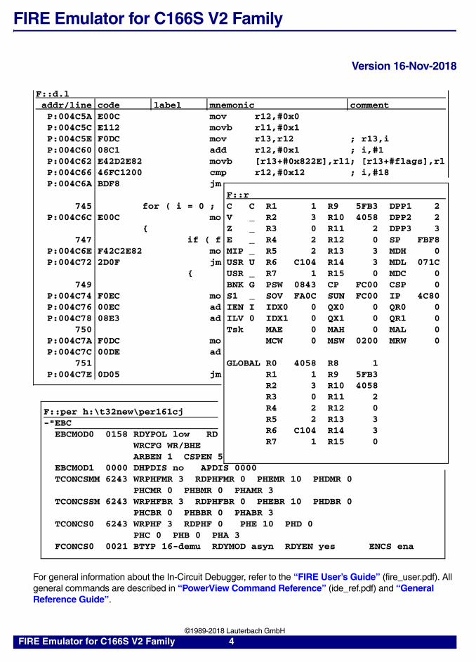
For general information about the In-Circuit Debugger, refer to the “FIRE User’s Guide” (fire_user.pdf). All general commands are described in “PowerView Command Reference” (ide_ref.pdf) and “General Reference Guide”.
F::d.laddr/line code label mnemonic commentP:004C5A E00C mov r12,#0x0P:004C5C E112 movb rl1,#0x1P:004C5E F0DC mov r13,r12 ; r13,iP:004C60 08C1 add r12,#0x1 ; i,#1P:004C62 E42D2E82 movb [r13+#0x822E],rl1; [r13+#flags],rlP:004C66 46FC1200 cmp r12,#0x12 ; i,#18P:004C6A BDF8 jm
F::r745 for ( i = 0 ; C C R1 1 R9 5FB3 DPP1 2
P:004C6C E00C mo V _ R2 3 R10 4058 DPP2 2{ Z _ R3 0 R11 2 DPP3 3
747 if ( f E _ R4 2 R12 0 SP FBF8P:004C6E F42C2E82 mo MIP _ R5 2 R13 3 MDH 0P:004C72 2D0F jm USR U R6 C104 R14 3 MDL 071C
{ USR _ R7 1 R15 0 MDC 0749 BNK G PSW 0843 CP FC00 CSP 0
P:004C74 F0EC mo S1 _ SOV FA0C SUN FC00 IP 4C80P:004C76 00EC ad IEN I IDX0 0 QX0 0 QR0 0P:004C78 08E3 ad ILV 0 IDX1 0 QX1 0 QR1 0
750 Tsk MAE 0 MAH 0 MAL 0P:004C7A F0DC mo MCW 0 MSW 0200 MRW 0P:004C7C 00DE ad
751P:004C7E 0D05 jm
F::per h:\t32new\per161cj-"EBC
EBCMOD0 0158 RDYPOL low RDWRCFG WR/BHEARBEN 1 CSPEN 5
EBCMOD1 0000 DHPDIS no APDIS 0000TCONCSMM 6243 WRPHFMR 3 RDPHFMR 0 PHEMR 10 PHDMR 0
PHCMR 0 PHBMR 0 PHAMR 3TCONCSSM 6243 WRPHFBR 3 RDPHFBR 0 PHEBR 10 PHDBR 0
PHCBR 0 PHBBR 0 PHABR 3TCONCS0 6243 WRPHF 3 RDPHF 0 PHE 10 PHD 0
PHC 0 PHB 0 PHA 3FCONCS0 0021 BTYP 16-demu RDYMOD asyn RDYEN yes ENCS ena
GLOBAL R0 4058 R8 1R1 1 R9 5FB3R2 3 R10 4058R3 0 R11 2R4 2 R12 0R5 2 R13 3R6 C104 R14 3R7 1 R15 0
FIRE Emulator for C166S V2 Family 4 ©1989-2018 Lauterbach GmbH

Warning
NOTE: Do not connect or remove probe from target while target power is ON.
Power up: Switch on emulator first, then targetPower down: Switch off target first, then emulator
FIRE Emulator for C166S V2 Family 5 ©1989-2018 Lauterbach GmbH

Quick Start
Before debugging can be started, the emulator must be configured by software:
Ready-to-run setup files for most standard compilers can be found on the software DVD in the directory ~~/demo/c166/compiler. All setup files are designed to run the emulator stand alone without target hardware.
The following description should make the initial setup (to run the emulator together with the target hardware) easier. It describes a typical setup with frequently used settings. It is recommended to use the programming language PRACTICE to create a script file, which includes all necessary setup commands. PRACTICE files (*.cmm) can be created with the PRACTICE editor PEDIT (Command: PEDIT <file_name>) or with any other text editor.
A basic setup file includes the following parts:
1. Set cpu-type and -mode
2. Set system options
3. Select dualport mode (optional)
4. Set mapper and CS definition (optional)
5. Select frequency (optional)
6. Activate the emulator
7. Load application file (optional)
8. Set breakpoints (optional)
9. Start application
10. Stop application (optional)
FIRE Emulator for C166S V2 Family 6 ©1989-2018 Lauterbach GmbH
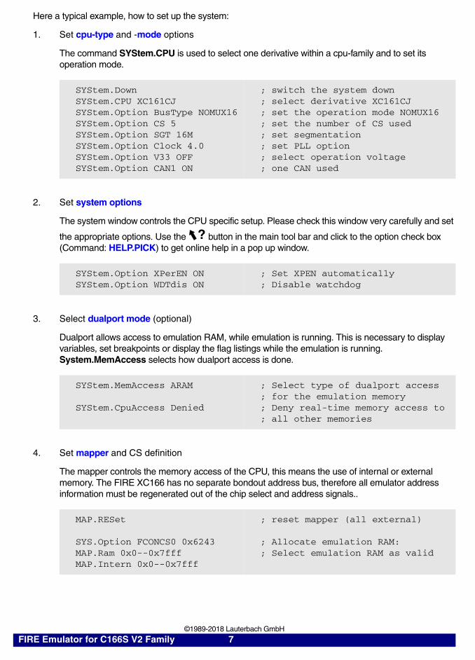
Here a typical example, how to set up the system:
1. Set cpu-type and -mode options
The command SYStem.CPU is used to select one derivative within a cpu-family and to set its operation mode.
2. Set system options
The system window controls the CPU specific setup. Please check this window very carefully and set
the appropriate options. Use the button in the main tool bar and click to the option check box (Command: HELP.PICK) to get online help in a pop up window.
3. Select dualport mode (optional)
Dualport allows access to emulation RAM, while emulation is running. This is necessary to display variables, set breakpoints or display the flag listings while the emulation is running. System.MemAccess selects how dualport access is done.
4. Set mapper and CS definition
The mapper controls the memory access of the CPU, this means the use of internal or external memory. The FIRE XC166 has no separate bondout address bus, therefore all emulator address information must be regenerated out of the chip select and address signals..
SYStem.DownSYStem.CPU XC161CJSYStem.Option BusType NOMUX16SYStem.Option CS 5SYStem.Option SGT 16MSYStem.Option Clock 4.0SYStem.Option V33 OFFSYStem.Option CAN1 ON
; switch the system down; select derivative XC161CJ; set the operation mode NOMUX16; set the number of CS used; set segmentation; set PLL option; select operation voltage; one CAN used
SYStem.Option XPerEN ONSYStem.Option WDTdis ON
; Set XPEN automatically ; Disable watchdog
SYStem.MemAccess ARAM
SYStem.CpuAccess Denied
; Select type of dualport access; for the emulation memory; Deny real-time memory access to; all other memories
MAP.RESet
SYS.Option FCONCS0 0x6243MAP.Ram 0x0--0x7fffMAP.Intern 0x0--0x7fff
; reset mapper (all external)
; Allocate emulation RAM: ; Select emulation RAM as valid
?
FIRE Emulator for C166S V2 Family 7 ©1989-2018 Lauterbach GmbH
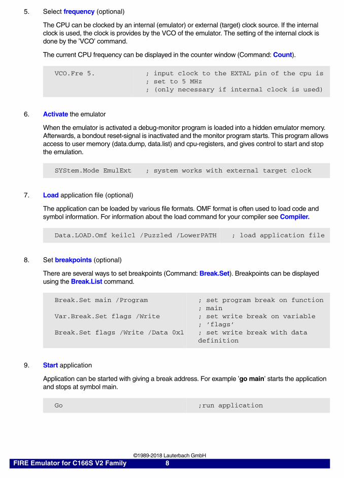
5. Select frequency (optional)
The CPU can be clocked by an internal (emulator) or external (target) clock source. If the internal clock is used, the clock is provides by the VCO of the emulator. The setting of the internal clock is done by the ’VCO’ command.
The current CPU frequency can be displayed in the counter window (Command: Count).
6. Activate the emulator
When the emulator is activated a debug-monitor program is loaded into a hidden emulator memory. Afterwards, a bondout reset-signal is inactivated and the monitor program starts. This program allows access to user memory (data.dump, data.list) and cpu-registers, and gives control to start and stop the emulation.
7. Load application file (optional)
The application can be loaded by various file formats. OMF format is often used to load code and symbol information. For information about the load command for your compiler see Compiler.
8. Set breakpoints (optional)
There are several ways to set breakpoints (Command: Break.Set). Breakpoints can be displayed using the Break.List command.
9. Start application
Application can be started with giving a break address. For example ’go main’ starts the application and stops at symbol main.
VCO.Fre 5. ; input clock to the EXTAL pin of the cpu is; set to 5 MHz; (only necessary if internal clock is used)
SYStem.Mode EmulExt ; system works with external target clock
Data.LOAD.Omf keilcl /Puzzled /LowerPATH ; load application file
Break.Set main /Program
Var.Break.Set flags /Write
Break.Set flags /Write /Data 0x1
; set program break on function; main; set write break on variable; ’flags’; set write break with data definition
Go ;run application
FIRE Emulator for C166S V2 Family 8 ©1989-2018 Lauterbach GmbH

10. Stop application (optional)
Application can be breaked manually by using the BREAK command.
It is recommended to check the following chapters for all questions regarding the correct setup:
• Configuration
• Troubleshooting
Break ; break application manually
FIRE Emulator for C166S V2 Family 9 ©1989-2018 Lauterbach GmbH

Configuration
Adapter XC161CJ/XC164CS
CPU Switch Settings S101
XC161CJ
XC164CS
VAGND/VAREF from Tar-get
VAGND to GND
S101
S102
BOTTOM VIEW
O F F
1 2 3 4 5 6 7 8
O F F
1 2 3 4 5 6 7 8
O F F
1 2 3 4 5 6 7 8
O F F
1 2 3 4 5 6 7 8
FIRE Emulator for C166S V2 Family 10 ©1989-2018 Lauterbach GmbH

VAREF to VCC
XTAL3 to internal 32 kHz clock
XTAL3 to target
CPU Switch Settings S102
Default
Fast Emulationon CS0 (XC161)
Fast Emulationon CS0 (XC164)
O F F
1 2 3 4 5 6 7 8
O F F
1 2 3 4 5 6 7 8
O F F
1 2 3 4 5 6 7 8
O F F
1 2 3 4 5 6 7 8
O F F
1 2 3 4 5 6 7 8
O F F
1 2 3 4 5 6 7 8
FIRE Emulator for C166S V2 Family 11 ©1989-2018 Lauterbach GmbH

Troubleshooting
Hang-Up Conditions
If you are not able to stop the emulation, there may be some typically reasons:
Dualport Errors
Dualport access is made either between bus cycles or by feeding NOP instructions (Bondout CPU). If no bus cycle is generated (IDLE or SLEEP), an dualport error occurs.
The ROM emulation memory system (DATA, BREAK, FLAG) is always accessible.
No READY Signal This condition occurs, if no READY signal is generated by the target.
WATCHDOG In C167/ST10 CPU has a watchdog system. Don't forget to disable the Software Watchdog before starting emulation.
IDLE oder PWRDWN The emulator can be stopped in idle or powerdown modes. Some restrictions depend on bondout errors.
FIRE Emulator for C166S V2 Family 12 ©1989-2018 Lauterbach GmbH

FAQ
Debugging via VPN
The debugger is accessed via internet/VPN and the performance is very slow. What can be done to improve debug performance?
The main cause for bad debug performance via internet or VPN are low data throughput and high latency. The ways to improve performance by the debugger are limited:
• in practice scripts, use "SCREEN.OFF" at the beginning of the script and"SCREEN.ON" at the end. "SCREEN.OFF" will turn off screen updates.Please note that if your program stops (e.g. on error) without executing"SCREEN.OFF", some windows will not
be updated.
• "SYStem.POLLING SLOW" will set a lower frequency for target statechecks (e.g. power, reset, jtag state). It will take longer for the debugger torecognize that the core stopped on a breakpoint.
• "SETUP.URATE 1.s" will set the default update frequency ofData.List/Data.Dump/Variable windows to 1 second (the slowest possiblesetting).
• prevent unneeded memory accesses using "MAP.UPDATEONCE[address-range]" for RAM and "MAP.CONST [address--range]" forROM/FLASH. Address ranged with "MAP.UPDATEONCE" will read thespecified address range only once after the core stopped at a
breakpoint or manual break. "MAP.CONST" will read the specified address range only once per SYStem.Mode command (e.g. SYStem.UP).
FIRE Emulator for C166S V2 Family 13 ©1989-2018 Lauterbach GmbH

Basics
The bondout module includes a separate 512K memory for ROM emulation up to 40/50 MHz. The ROM emulation is supported by a BREAKPOINT memory and a FLAG memory. These memories are dualported with no limitations.
FIRE Emulator for C166S V2 Family 14 ©1989-2018 Lauterbach GmbH

Overview
The C16x/ST10 specific part of TRACE32-FIRE consists of the following modules:
• Trigger Module
• Bondout Module
• CPU Module
IP Trace
IP Flag
IP Break
Data Trace
Data Flag
Data Break
Code Trace
Code Flag
Code Break
Write Trace
Write Flag
Write Break
Read Trace
Read Flag
Read Break
Shadow Memory
Trigger Module
BondoutFLASHEmulation
Boot Loader
Monitor RAM
Mapper
Trigger System
ROM Bus
External Bus
Trace Bus
Bondout Module
ClockGenerator
Ports
Target Adapter
PortAnalyzer
CPU Module
FastOverlayRAM(external)
FIRE Emulator for C166S V2 Family 15 ©1989-2018 Lauterbach GmbH

Trigger Module
The trigger module provides the follwing features:
Trace System The trace system is build by an 128 bit and 64K deep trace storage. All bondout signals are sampled by this unit. The trace works as a trace extension to the trace memory within the FIRE emulation controller.
Break System/Address Selectors
The break/address selector system consists of:• 4 * 1 MByte ranges to set (Operand) Read Breakpoints plus 4
data selectors• 4 * 1 MByte ranges to set (Operand) Write Breakpoints plus 4 data
sele tors• 8 * 1 MByte ranges to set Instruction Address Breakpoints plus 8
data selectors• 2 independent data selectors
Flag System The flag system is build by• 2 * 1 MByte ranges for Operand Read Flags • 2 * 1 MByte ranges for Operand Write Flags • 2 * 1 MByte ranges for Instruction Execution Flags• 2 * 1 MByte ranges for Jump Taken Flags
Shadow Memory 1 MByte shadow memory that can be used for IRAM/XRAM or external memory.
Trigger Unit The trigger unit combines address selectors to set trigger points (Alpha, Beta, Charly and Delta address selector).
Break Unit The break unit combines breakpoints to directly stop the emulation (Read, Write breakpoints).
Trigger Module
Bondout Module
CPU Module
FIRE Emulator for C166S V2 Family 16 ©1989-2018 Lauterbach GmbH
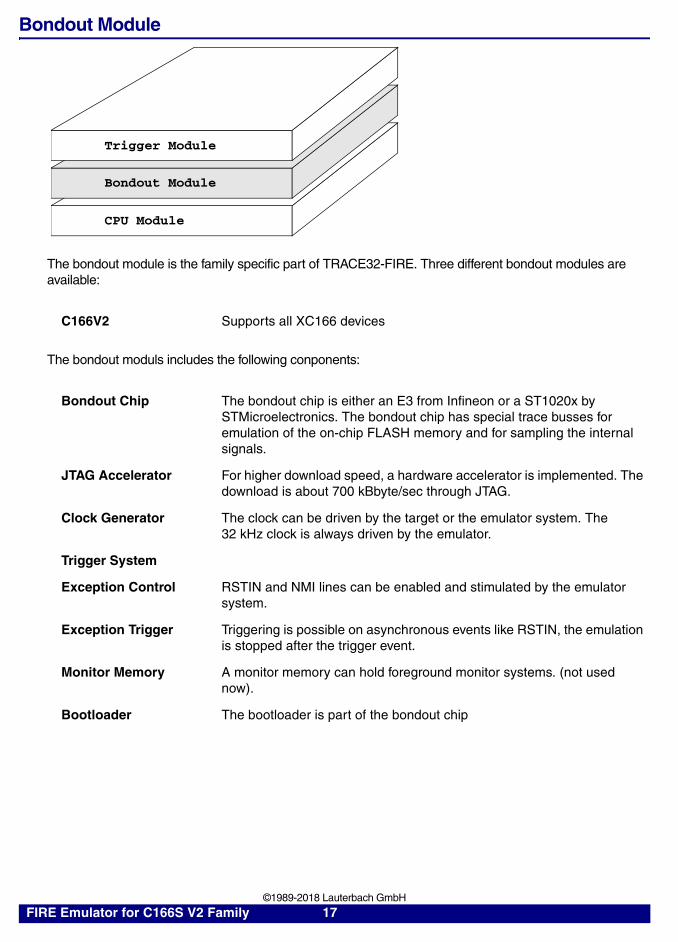
Bondout Module
The bondout module is the family specific part of TRACE32-FIRE. Three different bondout modules are available:
The bondout moduls includes the following conponents:
C166V2 Supports all XC166 devices
Bondout Chip The bondout chip is either an E3 from Infineon or a ST1020x by STMicroelectronics. The bondout chip has special trace busses for emulation of the on-chip FLASH memory and for sampling the internal signals.
JTAG Accelerator For higher download speed, a hardware accelerator is implemented. The download is about 700 kBbyte/sec through JTAG.
Clock Generator The clock can be driven by the target or the emulator system. The 32 kHz clock is always driven by the emulator.
Trigger System
Exception Control RSTIN and NMI lines can be enabled and stimulated by the emulator system.
Exception Trigger Triggering is possible on asynchronous events like RSTIN, the emulation is stopped after the trigger event.
Monitor Memory A monitor memory can hold foreground monitor systems. (not used now).
Bootloader The bootloader is part of the bondout chip
Trigger Module
Bondout Module
CPU Module
FIRE Emulator for C166S V2 Family 17 ©1989-2018 Lauterbach GmbH

Bondout Chip The XC166 bondout chip is a flip chip device, containing on one part all the emulation logic and on the other part the production chip for XC161/XC164. That means that on changing silicon step of the production chips, new emulation devices can be producted very quickly. The bondout chip is in a BGA socket and can be easily replaced by the customer.
FLASH/ROM Emulation Memory
A 128 K memory for ROM/FLASH overlay is placed on the bondout chip.
Mapper The mapper defines the mapping of the external emulation memory. Up to 16 MByte of memory can be supported. The FIREXC166 emulator uses asynchronous dualport emulation memory (ARAM).
FIRE Emulator for C166S V2 Family 18 ©1989-2018 Lauterbach GmbH

CPU Module
The CPU module is the device specific part of the FIRE-166 emulator.
Emulation Modes
The emulations head can stay in 5 modes. The modes are selected by the SYStem.Up or the SYStem.Mode command.
Target Connection The target connection is done by 100 mil socket rows. Clip-over, solder-on oder socket adapters can be used.
Port Analyzer MUX All signal pins can be traced by the port analyzer. Buffers to all peripheral signals are on the adapter board.
FAST Overlay RAM A 1 MByte 16 Bit overlay RAM, which can replace external FLASH devices for high-speed emulation (12 ns access).
Trigger Module
Bondout Module
CPU Module
F::syssystem Mode MemAccess Option
Down RESet ARAM TraceIntUp AloneInt CPU TraceExt
AloneExt GAP TraceResRESet EmulInt ROM Option
EmulExt Monitor IMASKASMCPU MIXed IMASKHLL
XC161CJ Denied TestClockCpuAccess V33
C166SV2 Enable WriteLimi Denied PERSTOP
reset Nonstop WDTSTOPRESetOut TimeReq
1.000msJtagClockCLK/4
FIRE Emulator for C166S V2 Family 19 ©1989-2018 Lauterbach GmbH

SYStem.Mode Operation modes
In active mode, the power of the target is sensed and by switching down the target the emulator changes to RESET mode. The probe is not supplied by the target. When running without target, the target voltage is simulated by an internal pull-up resistor. The command SYStem.Up in Stand-alone doesn't work correctly. Use SYStem.Mode AloneInt to select the correct emulation mode.
Format: SYStem.Mode <mode>
<mode>: RESetAloneIntAloneExtEmulIntEmulExt
RESet The probe is in Reset.
AloneInt Probe is running with internal clock, no target access possible.
AloneExt Probe is running with external clock, no target access possible.
EmulInt Probe is running with internal clock, target access is possible.
EmulExt Probe is running with external clock, target access is possible.
FIRE Emulator for C166S V2 Family 20 ©1989-2018 Lauterbach GmbH
SYStem.Access Dualport access
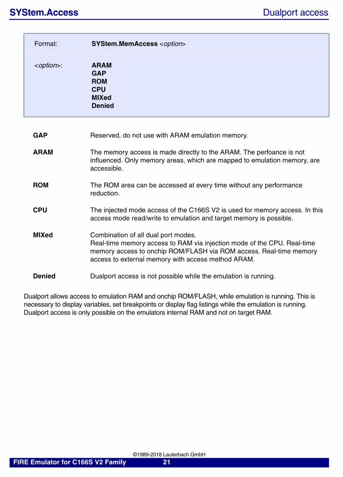
Dualport allows access to emulation RAM and onchip ROM/FLASH, while emulation is running. This is necessary to display variables, set breakpoints or display flag listings while the emulation is running. Dualport access is only possible on the emulators internal RAM and not on target RAM.
Format: SYStem.MemAccess <option>
<option>: ARAMGAPROMCPUMIXedDenied
GAP Reserved, do not use with ARAM emulation memory.
ARAM The memory access is made directly to the ARAM. The perfoance is not influenced. Only memory areas, which are mapped to emulation memory, are accessible.
ROM The ROM area can be accessed at every time without any performance reduction.
CPU The injected mode access of the C166S V2 is used for memory access. In this access mode read/write to emulation and target memory is possible.
MIXed Combination of all dual port modes.Real-time memory access to RAM via injection mode of the CPU. Real-time memory access to onchip ROM/FLASH via ROM access. Real-time memory access to external memory with access method ARAM.
Denied Dualport access is not possible while the emulation is running.
FIRE Emulator for C166S V2 Family 21 ©1989-2018 Lauterbach GmbH
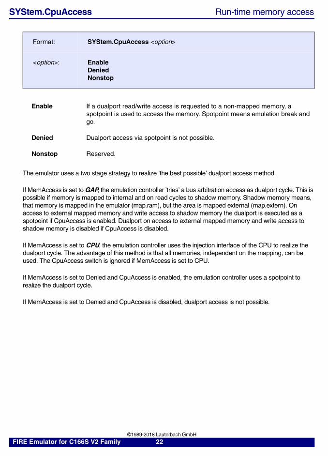
SYStem.CpuAccess Run-time memory access
The emulator uses a two stage strategy to realize ’the best possible’ dualport access method.
If MemAccess is set to GAP, the emulation controller ’tries’ a bus arbitration access as dualport cycle. This is possible if memory is mapped to internal and on read cycles to shadow memory. Shadow memory means, that memory is mapped in the emulator (map.ram), but the area is mapped external (map.extern). On access to external mapped memory and write access to shadow memory the dualport is executed as a spotpoint if CpuAccess is enabled. Dualport on access to external mapped memory and write access to shadow memory is disabled if CpuAccess is disabled.
If MemAccess is set to CPU, the emulation controller uses the injection interface of the CPU to realize the dualport cycle. The advantage of this method is that all memories, independent on the mapping, can be used. The CpuAccess switch is ignored if MemAccess is set to CPU.
If MemAccess is set to Denied and CpuAccess is enabled, the emulation controller uses a spotpoint to realize the dualport cycle.
If MemAccess is set to Denied and CpuAccess is disabled, dualport access is not possible.
Format: SYStem.CpuAccess <option>
<option>: EnableDeniedNonstop
Enable If a dualport read/write access is requested to a non-mapped memory, a spotpoint is used to access the memory. Spotpoint means emulation break and go.
Denied Dualport access via spotpoint is not possible.
Nonstop Reserved.
FIRE Emulator for C166S V2 Family 22 ©1989-2018 Lauterbach GmbH

The following table shows how the dualport is realized depending on the used system setting:
gap: The bus arbitration interface of the CPU is used for dualport access. Application performance is only slightly influenced.
cpu: The injection interface of the CPU is used for dualport access. Application performance is more influenced than with GAP mode.
spot: The emulation is breaked, memory access is done via CPU, emulation is continued. Application performance is most influenced with this method.
SYStem.TimeReq Sets dualport update intervall
MemAccess
CpuAccess
ReadMapInt.
WriteMapInt.
ReadShadow
WriteShadow
ReadMapExt.
WriteMapExt.
GAP Enable gap gap gap spot spot spot
GAP Denied gap gap gap - - -
CPU Enable cpu cpu cpu cpu cpu cpu
CPU Denied cpu cpu cpu cpu cpu cpu
Denied Enable spot spot spot spot spot spot
Denied Denied - - - - - -
Format: SYStem.TimeReq <time>
<time>: Update time intervall.
FIRE Emulator for C166S V2 Family 23 ©1989-2018 Lauterbach GmbH

General SYStem Settings and Restrictions
F::syssystem Mode MemAccess Option
Down RESet ARAM TraceIntUp AloneInt CPU TraceExt
AloneExt GAP TraceResRESet EmulInt ROM Option
EmulExt Monitor IMASKASMCPU MIXed IMASKHLL
XC161CJ Denied TestClockCpuAccess V33
C166SV2 Enable WriteLimi Denied PERSTOP
reset Nonstop WDTSTOPRESetOut TimeReq
1.000msJtagClockCLK/4
Option Option FConCSx AddrSelxResetMode ResetExt 0x6243OWDDIS ONCE 0x0 0x0WDTdis ONCEReset 0x0 0x0Option BOOTSTRAP 0x0 0x0
WRC 0x0 0x0Overlay BusType 0x0 0x0Start NOMUX8 0x0 0x0
Standard CS 0x0 0x0MonLevel 5 EBCMode0 EBCMode1
16. SGT 0x0 0x0InjLevel 16M
17. CLOCK0.5
FIRE Emulator for C166S V2 Family 24 ©1989-2018 Lauterbach GmbH

SYStem.CPU CPU type selection
The CPU type is selected. The CPU should be selected before activating the emulator and before using the first PER command. Selections which doesn’t fit to the probe used are ignored. Be sure that the switches on the probe have the correct setting.
SYStem.JtagClock JTAG clock selection
The JTAG clock should not be faster than 25% of the CPU clock frequency.
SYStem.Option MonLevel Monitor level
The monitor system can be interrupted. The monitor level defined the level, where all lower level interrupts are blocked.
Format: SYStem.CPU <cpu >
<cpu>: XC161CJXC164CS
Format: SYStem.JtagClock <rate >
<rate>: /2/4/81000000050000002500000
Format: SYStem.Option MonLevel <level>
<level>: 1. … 18.
FIRE Emulator for C166S V2 Family 25 ©1989-2018 Lauterbach GmbH

SYStem.Option InjLevel Injection level
Memory access by the debug system is made by injected instructions. The INJECT level defines the priority of this function. The inject level should be higher than the monitor level.
SYStem.Option V33 3.3 V power fail detection
The emulator has a detection logic to detect a target power fail. This option must be set to on, if a 3.3 V target is used.
NOTE: The C166S V2 bondout chip is specified for 5 V only.
SYStem.Option IMASKASM Mask interrupts during assembler step
If enabled, the interrupt mask bits of the cpu will be set during assembler single-step operations. The interrupt routine is not executed during single-step operations. After single step the interrupt mask bits are restored to the value before the step.
SYStem.Option IMASKHLL Mask interrupts during HLL step
If enabled, the interrupt mask bits of the cpu will be set during HLL single-step operations. The interrupt routine is not executed during single-step operations. After single step the interrupt mask bits are restored to the value before the step.
NOTE: By changing the status register through target software, this option can affect the flow of the target program. Accesses to the interrupt-mask bits will see the wrong values.
Format: SYStem.Option InjLevel <level>
<level>: 1. … 18.
Format: SYStem.Option V33 [ON | OFF]
Format: SYStem.Option IMASKASM [ON | OFF]
Format: SYStem.Option IMASKHLL [ON | OFF]
FIRE Emulator for C166S V2 Family 26 ©1989-2018 Lauterbach GmbH
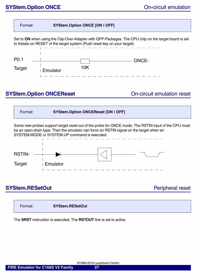
SYStem.Option ONCE On-circuit emulation
Set to ON when using the Clip-Over-Adapter with QFP-Packages. The CPU chip on the target board is set to tristate on RESET of the target system (Push reset key on your target).
SYStem.Option ONCEReset On-circuit emulation reset
Some new probes support target reset out of the probe for ONCE mode. The RSTIN input of the CPU must be an open-drain type. Then the emulator can force an RSTIN signal on the target when an SYSTEM.MODE or SYSTEM.UP command is executed.
SYStem.RESetOut Peripheral reset
The SRST instruction is executed. The RSTOUT line is set to active.
Format: SYStem.Option ONCE [ON | OFF]
Format: SYStem.Option ONCEReset [ON | OFF]
Format: SYStem.RESetOut
ONCE-P0.1
Target 10KEmulator
RSTIN-
Target Emulator
FIRE Emulator for C166S V2 Family 27 ©1989-2018 Lauterbach GmbH

SYStem.Option BusType Bus mode
Selects the bus mode for the processor.
SYStem.Option CS_Register CS programming
For correct operation of the XC161/XC164 emulators all chip-select and address-line related registers must be programmed before emulator is started. The address-regeneration is done by the emulator logic in hardware. The FConCS and AddrSel registers are programmed by the emulator system. They should not be changed later on.
Format: SYStem.Option BusType <mode>
<mode>: ROMENNOMUX8MUX8NOMUX16MUX16
ROMEN reserved.
NOMUX8 Non-multiplexed 8 bit bus. Port 0L is data port, Port 1 and 4 are address ports.
MUX8 Multiplexed 8 bit bus. Port 0 is used for address and data.
NOMUX16 Non-multiplexed 16 bit bus. Port 0 is data bus, port 1 and 4 are address signals.
MUX16 Multiplexed 16 Bit bus. Port 0 is address and data bus. The upper address lines (segments) are supported on port 4.
Format: SYStem.Option <cs_reg>
<cs_reg>: FConCS[7..0]AddrSel[7..0]EBCMode[1..0]
A16..A22
CS0..CS7A16..A23 to MemoryAddress
Regenerator
FIRE Emulator for C166S V2 Family 28 ©1989-2018 Lauterbach GmbH

SYStem.Option WriteLimit Write strobe limitation
The write strobe for the emulation RAM is limited. Ths option should be activated if chip selects with zero tristate cycles are used.
SYStem.Option Start-up modes
Format: SYStem.Option WriteLimit [ON | OFF]
Format: SYStem.Option <mode> [ON | OFF]
<mode>: BOOTSTRAPResetExtWRCResetMode
BOOTSTRAP Bootstrap Mode for C166S.
ResetExt The setup after RESET is defined by the target system. The internal setups (BOOTSTRAP, etc.) are ignored. This mode is valid for the C167 probe only.Usually the probe can use the reset vector from the target. However some targets supply this vector on reset of the target only (which must not be the same time as the reset of the emulator), or the pull-down resistors didn‘t work very fine (the buffers on Port 0 of the emulator need some input current). In all this situations the internal reset vectors should be used:SYStem.Option BusTypeSYStem.Option ChipSelectSYStem.Option ClockSYStem.Option BOOTSTRAPSYStem.Option WRCSYSTem.Option Start
WRC Activates the WRL/WRH mode.
ResetMode reserved.
FIRE Emulator for C166S V2 Family 29 ©1989-2018 Lauterbach GmbH
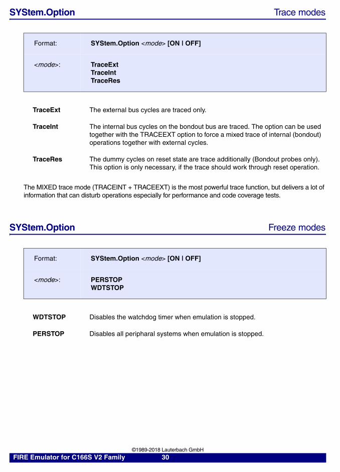
SYStem.Option Trace modes
The MIXED trace mode (TRACEINT + TRACEEXT) is the most powerful trace function, but delivers a lot of information that can disturb operations especially for performance and code coverage tests.
SYStem.Option Freeze modes
Format: SYStem.Option <mode> [ON | OFF]
<mode>: TraceExtTraceIntTraceRes
TraceExt The external bus cycles are traced only.
TraceInt The internal bus cycles on the bondout bus are traced. The option can be used together with the TRACEEXT option to force a mixed trace of internal (bondout) operations together with external cycles.
TraceRes The dummy cycles on reset state are trace additionally (Bondout probes only). This option is only necessary, if the trace should work through reset operation.
Format: SYStem.Option <mode> [ON | OFF]
<mode>: PERSTOPWDTSTOP
WDTSTOP Disables the watchdog timer when emulation is stopped.
PERSTOP Disables all peripharal systems when emulation is stopped.
FIRE Emulator for C166S V2 Family 30 ©1989-2018 Lauterbach GmbH

SYStem.Option Watchdog settings
SYStem.Option LoadCS Startup settings
SYStem.Option Overlay Overlay flash settings
Format: SYStem.Option <mode> [ON | OFF]
<mode>: WDTdisOWDDIS
WDTdis Disables the WDT (WatchDogTimer) while activating the emulator.
OWDDIS Oscillator Watchdog Disable.
Format: SYStem.Option LoadCS [ON | OFF]
LoadCS Load CS’s settings in EBC registers.
Format: SYStem.Option Overlay [ON | OFF]
Overlay Substitute onchip Flash memory with overlay memory.
FIRE Emulator for C166S V2 Family 31 ©1989-2018 Lauterbach GmbH

SYStem.Option Start Start modes
SYStem.Option TestClock Clock test
Format: SYStem.Option Start <mode>
<mode>: ExternalExternalPLLBootInternalAltExternalAltBootAltInternal
External Start from External Memory, PLL/OWD off (0x00’0000)
ExternalPLL Start from External Memory, PLL/OWD on (0x00’0000)
Boot Start from Boot memory (0xBF’0000)
Internal Start from Internal Program Memory (0xC0’0000)
AltExternal Alternate Start from External Memory
AltBoot Alternate Start from Boot memory
AltInternal Alternate Start from Internal Program Memory(0xC1’0000)
Format: SYStem.Option TestClock [ON | OFF]
TestClock The internal clock (ECLK or XTAL2) is checked by the emulator. If POWERDOWN modes are used, the TESTCLOCK option should be switched off.The clock test circuit is always active, if the emulation is stopped.
FIRE Emulator for C166S V2 Family 32 ©1989-2018 Lauterbach GmbH

SYStem.Option SGT Segmentation
The segmentation must be set up for all non-bondout probes. However it is recommended on the C167 bondout probe for correct address mirroring. The setup defines the reset vector in stand-alone mode.
SYStem.Option CS Chip selects
The reset vector for the chip selects is defined for all C167 probes.
SYStem.Option CLOCK PLL selects
The reset vector for the PLL multiplier is defined for all C167 probes.
Format: SYStem.Option SGT <size>
<size>: OFF256K1M16M
Format: SYStem.Option CS <size>
<size>: 0235
Format: SYStem.Option CLOCK <factor>
<factor>: 0.51.02.02.5L2.5H3.04.55.0
FIRE Emulator for C166S V2 Family 33 ©1989-2018 Lauterbach GmbH

Register Access
The XC166 devices contain 3 additional register set.
Register.Set R0G 1 ; set register R0 in global bank
Register.Set R0L1 1 ; set register R0 in local bank 1
F::rC _ R1 0 R9 5FB3 DPP1 1V _ R2 F000 R10 4251 DPP2 2Z _ R3 1 R11 C5C6 DPP3 3E _ R4 0 R12 CE5A SP FC00MIP _ R5 7FFF R13 DCB1 MDH 0USR _ R6 C104 R14 3267 MDL 0USR _ R7 1 R15 CFE8 MDC 0BNK G PSW 0 CP FC00 CSP 0S1 _ SOV FA00 SUN FC00 IP 0IEN _ IDX0 0 QX0 0 QR0 0ILV 0 IDX1 0 QX1 0 QR1 0Tsk MAE 0 MAH 0 MAL 0
MCW 0 MSW 0200 MRW 0
GLOBAL R0 3A01 R8 6B94R1 0 R9 5FB3R2 F000 R10 4251R3 1 R11 C5C6R4 0 R12 CE5AR5 7FFF R13 DCB1R6 C104 R14 3267R7 1 R15 CFE8
LOCAL1 R0 0 R8 F0R1 0100 R9 0100R2 F0 R10 F0R3 0100 R11 0100R4 F0 R12 F0R5 0100 R13 0100R6 F0 R14 F0R7 0100 R15 0100
LOCAL2 R0 F0 R8 F0R1 0100 R9 0100R2 F0 R10 F0R3 0100 R11 0100R4 F0 R12 F0R5 0100 R13 0100R6 F0 R14 F0R7 0100 R15 0100
FIRE Emulator for C166S V2 Family 34 ©1989-2018 Lauterbach GmbH

Exception Control
Schematics
RSTIN Line
NMI
RSTIN-(Target)
RSTIN-(CPU)
10K
Vcc
X.Enable
X.Activateor
X.Pulse
VDD
10K
NMI- Target
X.Enable->=1 & NMI- Cpu
X.Pulse-
FIRE Emulator for C166S V2 Family 35 ©1989-2018 Lauterbach GmbH
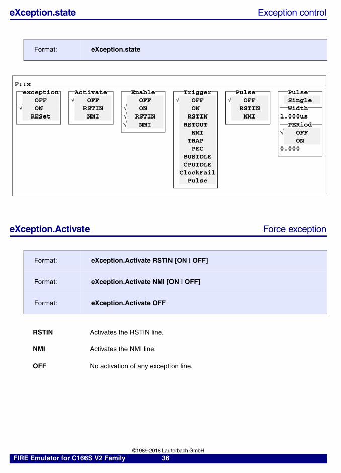
eXception.state Exception control
eXception.Activate Force exception
Format: eXception.state
Format: eXception.Activate RSTIN [ON | OFF]
Format: eXception.Activate NMI [ON | OFF]
Format: eXception.Activate OFF
RSTIN Activates the RSTIN line.
NMI Activates the NMI line.
OFF No activation of any exception line.
F::xexception Activate Enable Trigger Pulse Pulse
OFF OFF OFF OFF OFF Single ON RSTIN ON ON RSTIN Width
RESet NMI RSTIN RSTIN NMI 1.000us NMI RSTOUT PERiod
NMI OFFTRAP ONPEC 0.000
BUSIDLECPUIDLE
ClockFailPulse
FIRE Emulator for C166S V2 Family 36 ©1989-2018 Lauterbach GmbH

eXception.Enable Enable exception
eXception.Trigger Trigger on exception
Format: eXception.Enabke RSTIN [ON | OFF]
Format: eXception.Enable NMI [ON | OFF]
Format: eXception.Enable ON
Format: eXception.Enable OFF
RSTIN Enables the RSTIN line.
NMI Enables the NMI line.
ON Enables all exception line.
OFF Disables all exception lines.
Format: eXception.Trigger RSTIN [ON | OFF]
Format: eXception.Trigger RESET [ON | OFF]
Format: eXception.Trigger NMI [ON | OFF]
Format: eXception.Trigger BUSIDLE [ON | OFF]
Format: eXception.Trigger IDLE [ON | OFF]
Format: eXception.Trigger HLDA [ON | OFF]
Format: eXception.Trigger Pulse [ON | OFF]
Format: eXception.Trigger PEC [ON | OFF]
Format: eXception.Trigger PWRDOWN [ON | OFF]
FIRE Emulator for C166S V2 Family 37 ©1989-2018 Lauterbach GmbH

Format: eXception.Trigger RSTOUT [ON | OFF]
Format: eXception.Trigger TRAP [ON | OFF]
Format: eXception.Trigger TRAPACK [ON | OFF]
Format: eXception.Trigger OFF
Format: eXception.Trigger ON
RSTIN Trigger on RSTIN line.
RSTOUT Trigger on RSTOUT line.
NMI Trigger on NMI line.
TRAP Trigger on Trap execution.
PEC Trigger on PEC transfers.
BUSIDLE Trigger on Busidle.
CPUIDLE Trigger on Cpuidle.
ClockFail Trigger on Clock fail.
Pulse Trigger on Pulse.
ON Trigger on all exception lines.
OFF No trigger on any exception lines.
FIRE Emulator for C166S V2 Family 38 ©1989-2018 Lauterbach GmbH

eXception.Pulse Stimulate exception
Format: eXception.Pulse RSTIN [ON | OFF]
Format: eXception.Pulse NMI [ON | OFF]
Format: eXception.Pulse OFF
RSTIN Trigger on RSTIN line.
NMI Trigger on NMI line.
OFF No trigger on any exception line.
FIRE Emulator for C166S V2 Family 39 ©1989-2018 Lauterbach GmbH

Shadowing
Shadow Memory
The XRAM area can be supported by the emulator. When mapping external memory to this areas, the memory can be used as shadow memory.
Format: MAP.RAM <range>
MAP.RAM 0xc000--0xdfff ; activate shadow memory
Dump E:0xc000 ; show shadow memory
FIRE Emulator for C166S V2 Family 40 ©1989-2018 Lauterbach GmbH
Fast Emulation Memory
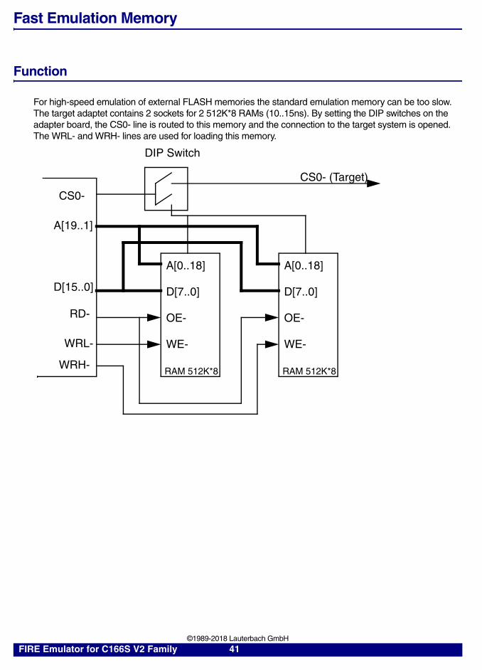
Function
For high-speed emulation of external FLASH memories the standard emulation memory can be too slow. The target adaptet contains 2 sockets for 2 512K*8 RAMs (10..15ns). By setting the DIP switches on the adapter board, the CS0- line is routed to this memory and the connection to the target system is opened. The WRL- and WRH- lines are used for loading this memory.
A[0..18]
D[7..0]
OE-
WE-
RAM 512K*8
A[0..18]
D[7..0]
OE-
WE-
RAM 512K*8
A[19..1]
D[15..0]
RD-
WRL-
WRH-
CS0-
DIP Switch
CS0- (Target)
FIRE Emulator for C166S V2 Family 41 ©1989-2018 Lauterbach GmbH

Bondout Trace
The bondout bus delivers information on the instruction pointer, the opcode, the operand data (result or operation) and the source and destination address. The bondout trace system makes filtering and dequeing of this busses to build qualified trace and trigger information. Valid trigger information is highlighted in the trace.
Every operation is shown in on trace frame. The IP address belongs to the source and destination address and the operand data.
Analyzer Modes
The analyzer can work in 3 different modes:
ADD1 Operand Read Address
ADD2 Operand Write Address
IP Instruction Pointer
OPC Opcode
OD Operand Data (result of operation)
MACH,MAC MAC Data
DPP Used DPP register
INJ Injected Instruction (e.g. interrupt)
NI New Instruction (marks first cycle)
BSEL Selected register bank
ILVL Status or PSW.ILVL field
TraceInt All cycles inside the CPU are traced, the external bus cycles are not traced.
TraceExt Only external bus cycles are traced. The internal breakpoints (OD, etc.) can be used for emulation break, but not for analyzer control.
TraceInt+TraceExt (TraceMixed)
In this mode the internal CPU cycles as well as the external bus cycles are traced.
FIRE Emulator for C166S V2 Family 42 ©1989-2018 Lauterbach GmbH

Bondout Trigger and Break System
Bondout Breakpoints
The breakpoint system is based on the bondout bus. The breakpoint information is filtered out of the program counter (instruction pointer), the operand read and write addresses and the resulting data of the operation. Every breakpoint can be qualified by a data word, byte, range or pattern.
Format: Break.Set <address> | <range> [/<mode> ...]
<mode>: ReadWriteProgramData[.<size>] <data>
<size>: autoByteWord
<data>: <value><range><mask>
Break.Set flags /write ; set write breakpoint on address; flags
Break.Set v.range(flags) /write ; set write breakpoint to full range; of array flags
Break.Set flags /read ; set read breakpoint
Break.Set sieve /program ; set software breakpoint on; function sieve
Break.Set sieve /p /hard ; set hardware breakpoint on function; sieve
FIRE Emulator for C166S V2 Family 43 ©1989-2018 Lauterbach GmbH

Bondout Trigger System
As all trace records are synchronized, and no prefetches are on the trace bus, triggering and selective sampling is very easy with the FIRE emulator. By using the program address qualifier, triggering on local variables is possible. Every qualifier is combined with a data qualifier.
Format: Break.Set <address> | <range> [/<mode> ...]
<mode>: AlphaBetaCharlyDeltaReadWriteProgramData[.<size>] <data>
<size>: autoByteWord
<data>: <value><range><mask>
Operand Read Address
Operand Write Addr.
Instruction Address
Data (Result)
Alpha
Beta
Charly
Delta
Data
Data
OAR Qualifier
OAW Qualifier
IP Qualifier
Data Qualifier
+
+
+
FIRE Emulator for C166S V2 Family 44 ©1989-2018 Lauterbach GmbH
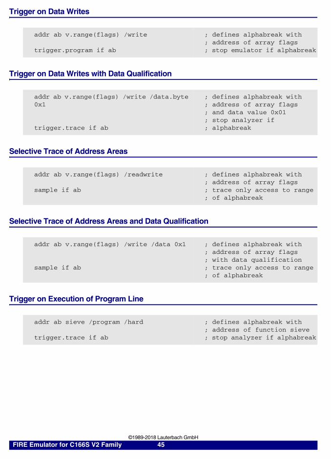
Trigger on Data Writes
Trigger on Data Writes with Data Qualification
Selective Trace of Address Areas
Selective Trace of Address Areas and Data Qualification
Trigger on Execution of Program Line
addr ab v.range(flags) /write
trigger.program if ab
; defines alphabreak with; address of array flags; stop emulator if alphabreak
addr ab v.range(flags) /write /data.byte 0x1
trigger.trace if ab
; defines alphabreak with; address of array flags; and data value 0x01; stop analyzer if; alphabreak
addr ab v.range(flags) /readwrite
sample if ab
; defines alphabreak with; address of array flags; trace only access to range; of alphabreak
addr ab v.range(flags) /write /data 0x1
sample if ab
; defines alphabreak with; address of array flags; with data qualification; trace only access to range; of alphabreak
addr ab sieve /program /hard
trigger.trace if ab
; defines alphabreak with; address of function sieve; stop analyzer if alphabreak
FIRE Emulator for C166S V2 Family 45 ©1989-2018 Lauterbach GmbH
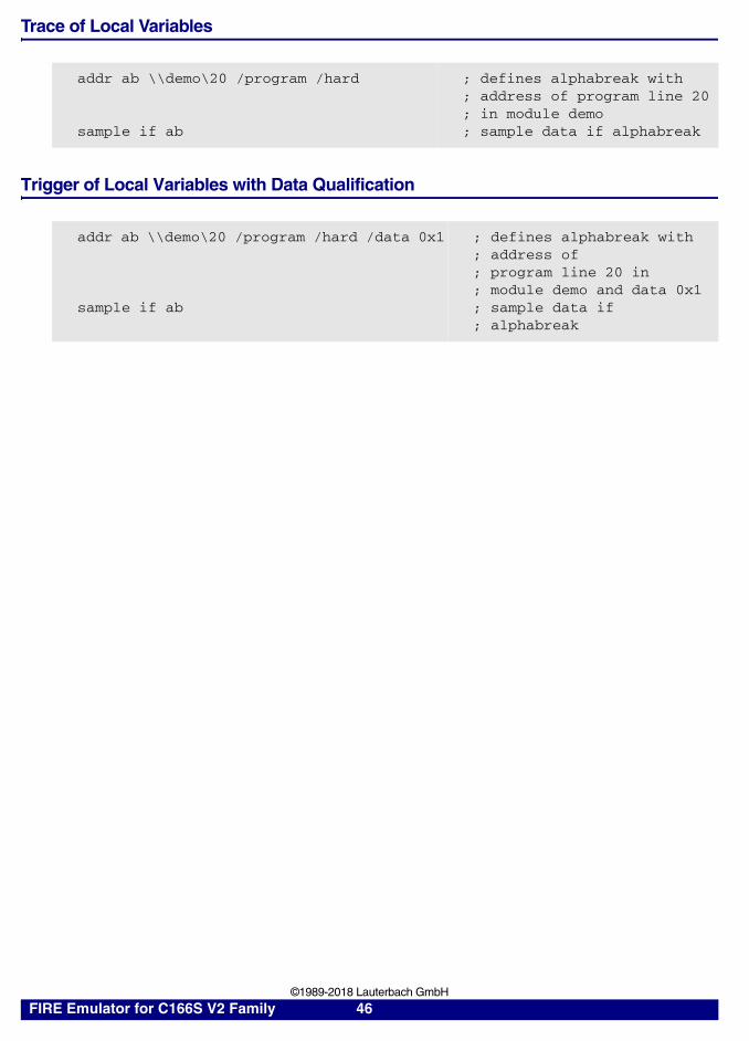
Trace of Local Variables
Trigger of Local Variables with Data Qualification
addr ab \\demo\20 /program /hard
sample if ab
; defines alphabreak with; address of program line 20; in module demo; sample data if alphabreak
addr ab \\demo\20 /program /hard /data 0x1
sample if ab
; defines alphabreak with; address of; program line 20 in; module demo and data 0x1; sample data if; alphabreak
FIRE Emulator for C166S V2 Family 46 ©1989-2018 Lauterbach GmbH

Code Flag System
Code Coverage
As prefetches are filtered by the bondout, the code coverage is 100% valid. The trigger system has 2 areas for code coverage with 1 MByte each. There are no restrictions on memory used by the program code. The code coverage works for external memory, ROM, XRAM and IRAM. There is no distinguish between BOOT ROM, ROM and external memory.
Flag Mapping
Flag mapping is done by:
Format: MAP.CFlag <addressrange>
Format: MAP.NoCFlag <addressrange>
MAP.CFlag 0--0xfffff ; supports the 1st MByte with ; code coverage memory
MAP.NoCFlag ; suspends code coverage
FIRE Emulator for C166S V2 Family 47 ©1989-2018 Lauterbach GmbH

Data Access Flags
Flag Operation
The data flag system works on all accesses with short and long addresses, in all types of memory. The flag system has 2 areas for read and write with 1 MByte each. Stack, register and bit operations are not covered by the flag system
The flag system works with byte resolution
Flag Mapping
Data flag mapping is done by:
Format: MAP.Flag <addressrange>MAP.ReadFlag <addressrange>MAP.WriteFlag <addressrange>
Format: MAP.NoFlag <addressrange>MAP.NoReadFlag <addressrange>MAP.NoWriteFlag <addressrange>
MAP.Flag 0--0xfffff ; supports the 1st MByte with ; read and write flag memory
MAP.NoFlag ; suspends flag mapping
FIRE Emulator for C166S V2 Family 48 ©1989-2018 Lauterbach GmbH

Bondout Based Dualport Systems
Bondout Shadow Memory
The shadow memory works for all short and long addressing modes in the external memory, the XRAM and IRAM.
The shadow memory is displayed, when the emulation is running and the
The shadow memory has 1 block with 1MByte length.
Injected Access
The C166S supports injected dualport access. A memory-memory transfer instruction is feeded to the instruction queue. This type of dualport access can access internal and external memory, IRAM and XRAM, as well as memory on the target system.
The injected access mode is used when CPU access is enabled (C166S only).
Format: MAP.Shadow <addressrange>
Format: MAP.NoShadow <addressrange>
FIRE Emulator for C166S V2 Family 49 ©1989-2018 Lauterbach GmbH
On-chip Trigger System
The bondout CPU has an onchip trigger unit with 16 IP Watchpoints and 32 Data Watchpoints. Every Watchpoint can be used as address range or as two independent breakpoint. They can be used if you would like to set a breakpoint in a target memory where no code can be patched (e.g. EPROM or Flash) The setting of the on-chip breakpoints in running mode is only possible when dualport access CPU or MIXED is enabled
Onchip prgram breakpoints are not working in a atomic or EXTended sequence. There are also ignore on a single cycle jump instruction.
FIRE Emulator for C166S V2 Family 50 ©1989-2018 Lauterbach GmbH

Special Functions
DPP( <offset> )
Returns the memory addressed by the short pointer argument. The lower 14 bits of the argument hold the offset, the two upper bits the DPP selector.
FIRE Emulator for C166S V2 Family 51 ©1989-2018 Lauterbach GmbH

Breakpoints
For a basic description of the breakpoint system please refer to FIRE User’s Guide.
Breakpoint Realization Modes
This chapter describes the different realization modes and shows their availability for the logical breakoints types.
The following table shows realization of the logical breakpoint types in auto-mode.
SoftwareBreakpoints
The user application code is patched with a special break-instruction of the bondout CPU (opcode 0x8C00) before jumping into the user program. After executing this instruction, the CPU stops the user program and jumps into the emulator debug monitor.
HardwareBreakpoints
These breakpoints are used as address selectors for the trigger unit (see FIRE User’s Guide).
On-chipBreakpoints
The bondout CPU has an onchip trigger-unit with 16 IP Watchpoints and 32 Data WatchpointsThey can be used if you would like to set a breakpoint in a target memory where no code can be patched (e.g. EPROM or Flash).
Breakpoint Type Realization in Auto Mode
Program SoftwareOn-chip (If the address is mapped as ReadOnly)On-chip (If the CPU is in running mode)
HLL SoftwareOn-chip (If the address is mapped as ReadOnly)Stepmode (If HLL-Line is too complex)
Spot SoftwareOn-chip (If the address is mapped as ReadOnly)
Read, Write Hardware
Alpha, Beta, Charly, Delta, Echo
Hardware
FIRE Emulator for C166S V2 Family 52 ©1989-2018 Lauterbach GmbH

Memory Classes
Memory Class Description
DP
DataProgram
XRLB
External AreaROM/Flash AreaBootloader AreaBit
CEA
Memory access by CPUEmulation memory accessAbsolute (physical) memory access
FIRE Emulator for C166S V2 Family 53 ©1989-2018 Lauterbach GmbH
State Analyzer
General 80166 Keywords for the Trigger Unit
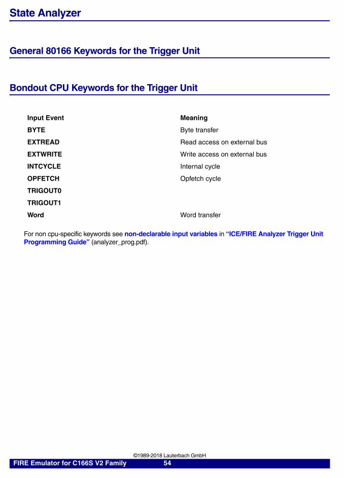
Bondout CPU Keywords for the Trigger Unit
For non cpu-specific keywords see non-declarable input variables in “ICE/FIRE Analyzer Trigger Unit Programming Guide” (analyzer_prog.pdf).
Input Event Meaning
BYTE Byte transfer
EXTREAD Read access on external bus
EXTWRITE Write access on external bus
INTCYCLE Internal cycle
OPFETCH Opfetch cycle
TRIGOUT0
TRIGOUT1
Word Word transfer
FIRE Emulator for C166S V2 Family 54 ©1989-2018 Lauterbach GmbH

Keywords for the Display
Bondout Information Display
The information from the bondout busses is displayed in the way like external operations. In mixed trace mode bondout data display is omitted, when it matches an external cycle. Cycles which sample only internal bondout information are marked as DUMMY cycles. Cycles which contain only external information have the EXTONLY flag set. Internal bondout cycles get the timestamp and external line information of the closest cycle if possible. This allows the display of timestamp and external lines even when the processor has no external bus activities. Variable accesses can be displayed in HLL form even for register and stack variables (Var command).
WR Write Bus Cycle
IPIPYOPCODADD1ADD1YADD2ADD2Y
Instruction Execution AddressSymbolic Instruction Execution AddressOp CodeResult DataOperand Address Readsame symbolicOperand Address Writesame symbolic
DPPINJNIBSELILVL
DPP select (shows which DPP register is used)Injected instruction (e.g. interrupt)New Instruction (marks first cycle of an instructionBank select (show selected register bank)Interrupt Level (status if ILVL field of PSW register)
List.BondoutList.NoDummy
Display internal bus information (included in default)Suppress dummy cycles (included in default)
FIRE Emulator for C166S V2 Family 55 ©1989-2018 Lauterbach GmbH

Port Analyzer
Port Signals XC161CJ
Port Signals XC164CM
Name Group Description
NMI- MISC Line NMI-
RSTIN- MISC Line RSTIN-
P000 .. P015 P0 Port P000 .. P015
P100 .. P115 P1 Port P100 .. P115
P208 .. P215 P2 Port P208 .. P215
P2000 .. P2002 P20 Port P2000 .. P2002
P2004 .. P2005 P20 Port P2004 .. P2005
P2012 P20 Port P2012
P300 .. P313 P3 Port P300 .. P313
P315 P3 Port P315
P400 .. P407 P4 Port P400 .. P407
P500 .. P515 P5 Port P500 .. P515
P600 .. P607 P6 Port P600 .. P607
P704 .. P707 P7 Port P704 .. P707
P900 .. P905 P9 Port P900 .. P905
Name Group Description
NMI- MISC Line NMI-
RSTIN- MISC Line RSTIN-
P100 .. P113 P1 Port P100 .. P113
P301 .. P311 P3 Port P301 .. P311
P313 P3 Port P313
P315 P3 Port P315
P500 .. P507 P5 Port P500 .. P507
P510 .. P515 P5 Port P510 .. P515
P900 .. P905 P9 Port P900 .. P905
FIRE Emulator for C166S V2 Family 56 ©1989-2018 Lauterbach GmbH

Port Signals XC164CS
Name Group Description
NMI- MISC Line NMI-
RSTIN- MISC Line RSTIN-
P000 .. P015 P0 Port P000 .. P015
P100 .. P115 P1 Port P100 .. P115
P2000 .. P2001 P20 Port P2000 .. P2001
P2004 .. P2005 P20 Port P2004 .. P2005
P2012 P20 Port P2012
P301 .. P313 P3 Port P301 .. P313
P315 P3 Port P315
P400 .. P407 P4 Port P400 .. P407
P500 .. P515 P5 Port P500 .. P515
P900 .. P905 P9 Port P900 .. P905
FIRE Emulator for C166S V2 Family 57 ©1989-2018 Lauterbach GmbH
Technical Data
Mechanical Dimensions
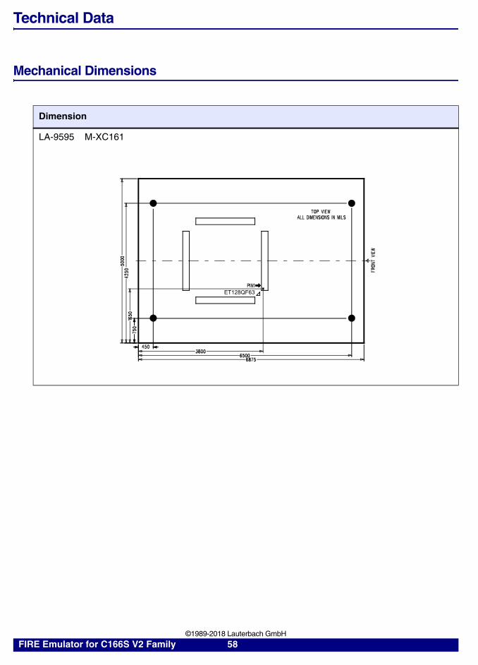
Dimension
LA-9595 M-XC161
ET128QF63
FIRE Emulator for C166S V2 Family 58 ©1989-2018 Lauterbach GmbH

LA-9596 M-XC164CS
LA-9597 M-XC164CM
Dimension
ET128QF49 PIN1 PIN1ET100QF49
TOP VIEWALL DIMENSIONS IN MILS
FR
ON
T V
IEW
500
04
250
1900
165
07
50
4503800
51006500
6875
TOP VIEW
ALL DIMENSIONS IN MILS
FR
ON
T V
IEW
PIN1 ET64QF64
68756500
4225450
750
215
042
5050
00
FIRE Emulator for C166S V2 Family 59 ©1989-2018 Lauterbach GmbH

Adaptions
CPU Adaption
XC164CSXC164DXC164NXC164S
ET100-QF49
XC161CJXC161CSXC167CI
ET144-QF63
FIRE Emulator for C166S V2 Family 60 ©1989-2018 Lauterbach GmbH

Adapters
Socket CPU Adapter
ET100-QF49
XC164CSXC164DXC164NXC164S
YA-1091 ET100-EYA-QF49Emul. Adapter for YAMAICHI socket ET100-QF49
6
56
SIDE VIEW
8
66
18
14
TOP VIEW (all dimensions in mm)
1
FIRE Emulator for C166S V2 Family 61 ©1989-2018 Lauterbach GmbH

Operation Voltage
This list contains information on probes available for other voltage ranges. Probes not noted here supply an operation voltage range of 4.5 … 5.5 V.
No other voltage ranges available !
ET144-QF63
XC161CJXC161CSXC167CI
YA-1111 ET144-EYA-QF63Emul. Adapter for YAMAICHI socket ET144-QF63
Socket CPU Adapter
6
69
SIDE VIEW
8
69
17
18
TOP VIEW (all dimensions in mm)
FIRE Emulator for C166S V2 Family 62 ©1989-2018 Lauterbach GmbH
Operation Frequency
Module CPU F-W0-10
F-W1-10
S-W0-10
S-W1-10
CHIP TRACE HEAD RAM
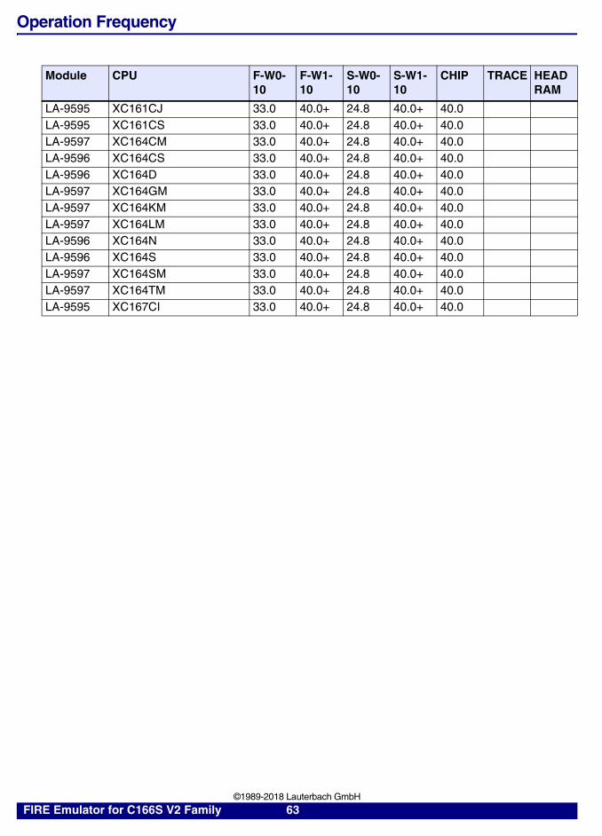
LA-9595 XC161CJ 33.0 40.0+ 24.8 40.0+ 40.0LA-9595 XC161CS 33.0 40.0+ 24.8 40.0+ 40.0LA-9597 XC164CM 33.0 40.0+ 24.8 40.0+ 40.0LA-9596 XC164CS 33.0 40.0+ 24.8 40.0+ 40.0LA-9596 XC164D 33.0 40.0+ 24.8 40.0+ 40.0LA-9597 XC164GM 33.0 40.0+ 24.8 40.0+ 40.0LA-9597 XC164KM 33.0 40.0+ 24.8 40.0+ 40.0LA-9597 XC164LM 33.0 40.0+ 24.8 40.0+ 40.0LA-9596 XC164N 33.0 40.0+ 24.8 40.0+ 40.0LA-9596 XC164S 33.0 40.0+ 24.8 40.0+ 40.0LA-9597 XC164SM 33.0 40.0+ 24.8 40.0+ 40.0LA-9597 XC164TM 33.0 40.0+ 24.8 40.0+ 40.0LA-9595 XC167CI 33.0 40.0+ 24.8 40.0+ 40.0
FIRE Emulator for C166S V2 Family 63 ©1989-2018 Lauterbach GmbH

Support
Probes
Available Tools
CP
U
ICE
FIR
E
ICD
DE
BU
G
ICD
MO
NIT
OR
ICD
TR
AC
E
PO
WE
RIN
TE
GR
ATO
R
INS
TR
UC
TIO
NS
IMU
LA
TOR
XC161CJ YES YES YES YESXC161CS YES YES YES YESXC164CM YES YES YES YESXC164CS YES YES YES YESXC164D YES YES YES YESXC164GM YES YES YES YESXC164KM YES YES YES YESXC164LM YES YES YES YES
XC161CJ ET144-QF63
XC161CS ET144-QF63
XC167CI ET144-QF63
LA-9595
XC164CS ET100-QF49
XC164D ET100-QF49
XC164N ET100-QF49
XC164S ET100-QF49
LA-9596
XC164CM ET64-QF64
XC164GM ET64-QF64
XC164KM ET64-QF64
XC164LM ET64-QF64
XC164SM ET64-QF64
XC164TM ET64-QF64
LA-9597
LA-9606
FIRE Emulator for C166S V2 Family 64 ©1989-2018 Lauterbach GmbH

Compilers
Target Operating Systems
XC164N YES YES YES YESXC164S YES YES YES YESXC164SM YES YES YES YESXC164TM YES YES YES YESXC167CI YES YES YES YES
Language Compiler Company Option Comment
C XC16X/ST10 Cosmic Software ELF/DWARFC GNU-GCC166 HighTec EDV-Systeme
GmbHDBX
C C166 ARM Germany GmbH EOMF-166C C166 TASKING IEEEC++ GNU-CPP166 HighTec EDV-Systeme
GmbHDBX
C++ CP166 TASKING IEEE
Company Product Comment
ARM Germany GmbH ARTX-166CMX Systems Inc. CMX-RTXElektrobit Automotive GmbH
Elektrobit tresos via ORTI
Evidence Erika via ORTIMentor Graphics Corporation
Nucleus PLUS
Vector osCAN via ORTIEnea OSE Systems OSE Basic (OS166)Enea OSE Systems OSE Epsilon (OS166), 3.x- OSEK via ORTI
CP
U
ICE
FIR
E
ICD
DE
BU
G
ICD
MO
NIT
OR
ICD
TR
AC
E
PO
WE
RIN
TE
GR
ATO
R
INS
TR
UC
TIO
NS
IMU
LA
TOR
FIRE Emulator for C166S V2 Family 65 ©1989-2018 Lauterbach GmbH
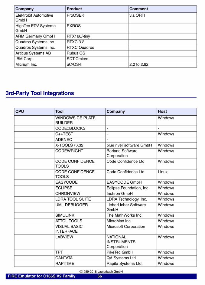
3rd-Party Tool Integrations
Elektrobit Automotive GmbH
ProOSEK via ORTI
HighTec EDV-Systeme GmbH
PXROS
ARM Germany GmbH RTX166/-tinyQuadros Systems Inc. RTXC 3.2Quadros Systems Inc. RTXC QuadrosArticus Systems AB Rubus OSIBM Corp. SDT-CmicroMicrium Inc. uC/OS-II 2.0 to 2.92
CPU Tool Company Host
WINDOWS CE PLATF. BUILDER
- Windows
CODE::BLOCKS - -C++TEST - WindowsADENEO -X-TOOLS / X32 blue river software GmbH WindowsCODEWRIGHT Borland Software
CorporationWindows
CODE CONFIDENCE TOOLS
Code Confidence Ltd Windows
CODE CONFIDENCE TOOLS
Code Confidence Ltd Linux
EASYCODE EASYCODE GmbH WindowsECLIPSE Eclipse Foundation, Inc WindowsCHRONVIEW Inchron GmbH WindowsLDRA TOOL SUITE LDRA Technology, Inc. WindowsUML DEBUGGER LieberLieber Software
GmbHWindows
SIMULINK The MathWorks Inc. WindowsATTOL TOOLS MicroMax Inc. WindowsVISUAL BASIC INTERFACE
Microsoft Corporation Windows
LABVIEW NATIONAL INSTRUMENTS Corporation
Windows
TPT PikeTec GmbH WindowsCANTATA QA Systems Ltd WindowsRAPITIME Rapita Systems Ltd. Windows
Company Product Comment
FIRE Emulator for C166S V2 Family 66 ©1989-2018 Lauterbach GmbH
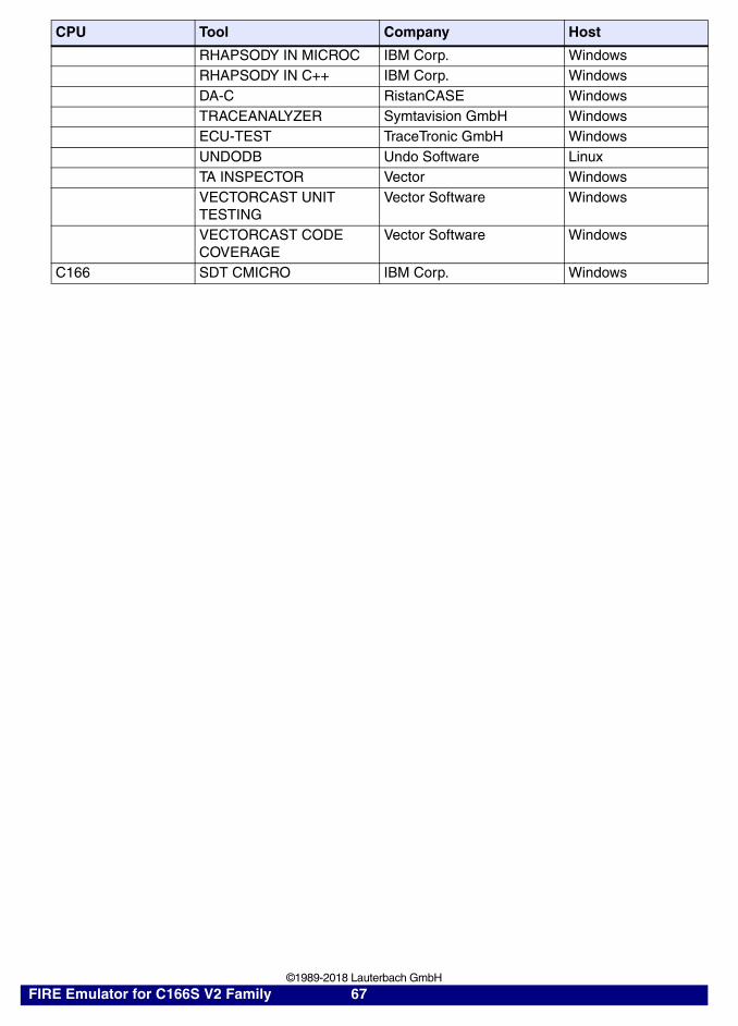
RHAPSODY IN MICROC IBM Corp. WindowsRHAPSODY IN C++ IBM Corp. WindowsDA-C RistanCASE WindowsTRACEANALYZER Symtavision GmbH WindowsECU-TEST TraceTronic GmbH WindowsUNDODB Undo Software LinuxTA INSPECTOR Vector WindowsVECTORCAST UNIT TESTING
Vector Software Windows
VECTORCAST CODE COVERAGE
Vector Software Windows
C166 SDT CMICRO IBM Corp. Windows
CPU Tool Company Host
FIRE Emulator for C166S V2 Family 67 ©1989-2018 Lauterbach GmbH

Products
Product Information
OrderNo Code Text
LA-9606 FIRE-XC166
FIRE Emulator for XC16xBondout Module for XC166 family,256K Flash Emulation, 5 Volt operation,40 MHz Operation with bondoutrequires FIRE-ARAM for external memory emulationrequires Trigger Module for XC166(LA-9607)
LA-9607 FIRE-XC166-TRIGG-64K
Trigger Module for XC166224 Trace Channels, Bondout Trigger System,Bondout Flag System, Shadow RAM, 64K Trace
LA-9632 FIRE-XC166-TRIGG-512
Trigger Module for XC166 512K224 Trace Channels, Bondout Trigger System,Bondout Flag System, Shadow RAM, 512K Trace
LA-9595 M-XC161
Module for XC161, XC167Module for TQFP144,ET128QF63supports XC161 and XC167
LA-9596 M-XC164CS
Module for XC164CSModule for ET100-QF49,supports XC164CS, XC164D, XC164S and XC164N
LA-9597 M-XC164CM
Module for XC164CMModule for ET64-QF64supports XC164CM, XC164LM and XC164SM
FIRE Emulator for C166S V2 Family 68 ©1989-2018 Lauterbach GmbH

Order Information
Order No. Code Text
LA-9606 FIRE-XC166 FIRE Emulator for XC16xLA-9607 FIRE-XC166-TRIGG-64K Trigger Module for XC166LA-9632 FIRE-XC166-TRIGG-512 Trigger Module for XC166 512KLA-9595 M-XC161 Module for XC161, XC167LA-9596 M-XC164CS Module for XC164CSLA-9597 M-XC164CM Module for XC164CM
Additional OptionsLA-7512 MON-166 ROM Monitor for C166/ST10 on ESILA-7759 OCDS-C166S-V2 OCDS Debugger for XC2000/C166S V2 (ICD)LA-2813L SIMULATOR-C166-FL 1 User Float. Lic. TRACE32 C166 Simulator
FIRE Emulator for C166S V2 Family 69 ©1989-2018 Lauterbach GmbH