fire gas water - shield | trusted · pdf fileshield polyethylene piping system innovation in...
TRANSCRIPT
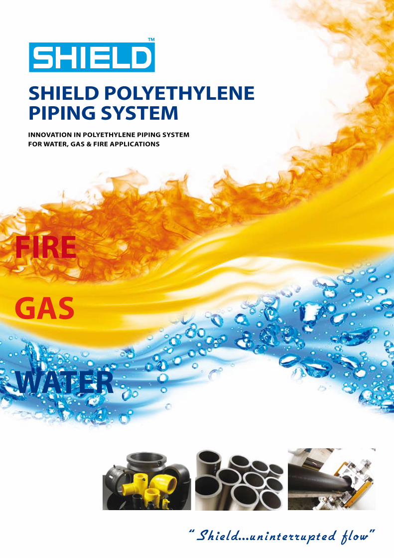
SHIELD POLYETHYLENE PIPING SYSTEMINNOVATION IN POLYETHYLENE PIPING SYSTEM FOR WATER, GAS & FIRE APPLICATIONS
WATER
GAS
FIRE
1
COMPANY PROFILE
HDPE PIPING SYSTEM
To learn more about shield, visit our website at: WWW.SHIELDGLOBAL.COM
Shield is a company created to cater to the infrastructure, fire protection and building service industries with a comprehensive range of products designed to be competitive and of assured quality.
We stay ahead of today’s ever evolving market requirements by committing to a program of continual research and development.
We are able to maintain our high standards by ensuring that our worldwide manufacturing centers are the most advanced in the industry. Our fully experienced and professional staff is there to provide engineering expertise and after sales service exactly when you need it.
Combine this with highly responsive and customer focused network of distribution centers around the world and you will find that customer satisfaction is what we excel at.
We are justifiably proud of our global client base. With offices in the UK, Middle East and Africa, we are able to comprehend the specific needs of your particular region.
Today, Shield proudly serves clients across the Gulf Countries & Middle East by manufacturing HDPE pipes and fittings in U.A.E to the highest quality standards and certification.
2
CONTENTS
Company Profile .....................................................................
Introduction .............................................................................
Characteristics of Shield HDPE ...........................................
Physical Properties of Shield HDPE ...................................
Design Stress & Safety Factor .............................................
Pipe SDR and Pressure Relationships ...............................
Pipe Size Chart as per ISO4427 ..........................................
Manufacturing & Quality Control ......................................
Water Line .................................................................................
Fittings Range .........................................................................
Gas Line .....................................................................................
Fire Line .....................................................................................
Fusion Machines ....................................................................
1334456789
111213
HDPE PIPING SYSTEM
3
We recommend Shield HDPE as your piping solution due to the following characteristics:
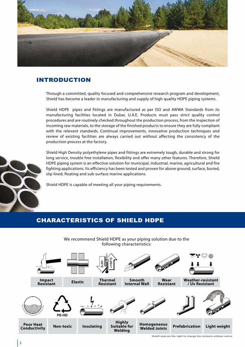
Through a committed, quality focused and comprehensive research program and development, Shield has become a leader in manufacturing and supply of high quality HDPE piping systems.
Shield HDPE pipes and fittings are manufactured as per ISO and AWWA Standards from its manufacturing facilities located in Dubai, U.A.E. Products must pass strict quality control procedures and are routinely checked throughout the production process, from the inspection of incoming raw materials, to the storage of the finished products to ensure they are fully compliant with the relevant standards. Continual improvements, innovative production techniques and review of existing facilities are always carried out without affecting the consistency of the production process at the factory. Shield High Density polyethylene pipes and fittings are extremely tough, durable and strong for long service, trouble free installation, flexibility and offer many other features. Therefore, Shield HDPE piping system is an effective solution for municipal, industrial, marine, agricultural and fire fighting applications. Its efficiency has been tested and proven for above ground, surface, buried, slip lined, floating and sub-surface marine applications.
Shield HDPE is capable of meeting all your piping requirements.
Impact Resistant Elastic Thermal
ResistantSmooth
Internal WallWear
ResistantWeather-resistant
/ Uv Resistant
! !
Poor Heat Conductivity Non-toxic Insulating
Highly Suitable for
WeldingHomogeneous Welded Joints Prefabrication Light weight
INTRODUCTION
CHARACTERISTICS OF SHIELD HDPE
Shield reser ves the r ight to change the contents without not ice.
4
HDPE PIPING SYSTEM
,c=1.25MRSc
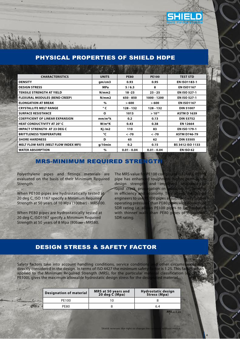
Polyethylene pipes and fittings materials are evaluated on the basis of their Minimum Required Strength.
When PE100 pipes are hydrostatically tested at 20 deg C, ISO 1167 specify a Minimum Required Strength at 50 years of 10 Mpa (100bar) - MRS100.
When PE80 pipes are hydrostatically tested at20 deg C, ISO1167 specify a Minimum Required Strength at 50 years of 8 Mpa (80bar) - MRS80.
CHARACTERISTICS UNITS PE80 PE100 TEST STD
DENSITY gm/cm3 0.93 0.95 EN ISO1183-1
DESIGN STRESS MPa 5 / 6.3 8 EN ISO1167
TENSILE STRENGTH AT YIELD N/mm2 18 -23 23 - 25 EN ISO 527-1
FLEXURAL MODULES (BEND CREEP) N/mm2 650 - 850 1000 - 1200 EN ISO 527-1
ELONGATION AT BREAK % > 600 > 600 EN ISO1167
CRYSTALLITE MELT RANGE ° C 128 - 132 128 - 132 DIN 51007
SURFACE RESISTANCE O 1013 > 1014 ASTM D 1639
COEFFICIENT OF LINEAR EXPANSION mm/m*k 0.2 0.13 DIN 53752
HEAT CONDUCTIVITY AT 20° C W/m*K 0.43 0.38 EN 12664
IMPACT STRENGTH AT 23 DEG C Kj /m2 110 83 EN ISO 179-1
BRITTLENESS TEMPERATURE °C < -70 < -70 ASTM D746-79
SHORE HARDNESS D 65 62 DIN 53505
MELT FLOW RATE (MELT FLOW INDEX MFI) g/10min 0.2 0.15 BS 3412 ISO 1133
WATER ABSORPTION % 0.01 - 0.04 0.01 - 0.04 EN ISO 62
The MRS value for PE100 compound is 10MPa. PE100 pipe has enhanced toughness, higher permissible design strength and improved resistance to rapid crack propagation in addition to benefits in efficiency and economy. This allows the design engineers to use PE100 pipes at substantially higher operating pressures than PE80 pipes with equivalent SDR rating i.e. allows PE100 pipes to be produced with thinner walls than PE80 pipes of equivalent SDR rating.
Designation of material MRS at 50 years and 20 deg C (Mpa)
Hydrostatic design Stress (Mpa)
PE100 10 8
PE80 8 6.4
Safety factors take into account handling conditions, service conditions and other circumstances not directly considered in the design. In terms of ISO 4427 the minimum safety factor is 1.25. This factor, when applied to the Minimum Required Strength (MRS), for the particular material classification (e.g. PE80, PE100), gives the maximum allowable hydrostatic design stress for the designated material.
MRS-MINIMUM REQUIRED STRENGTH
Shield reser ves the r ight to change the contents without not ice.
PHYSICAL PROPERTIES OF SHIELD HDPE
DESIGN STRESS & SAFETY FACTOR
5
HDPE PIPING SYSTEM
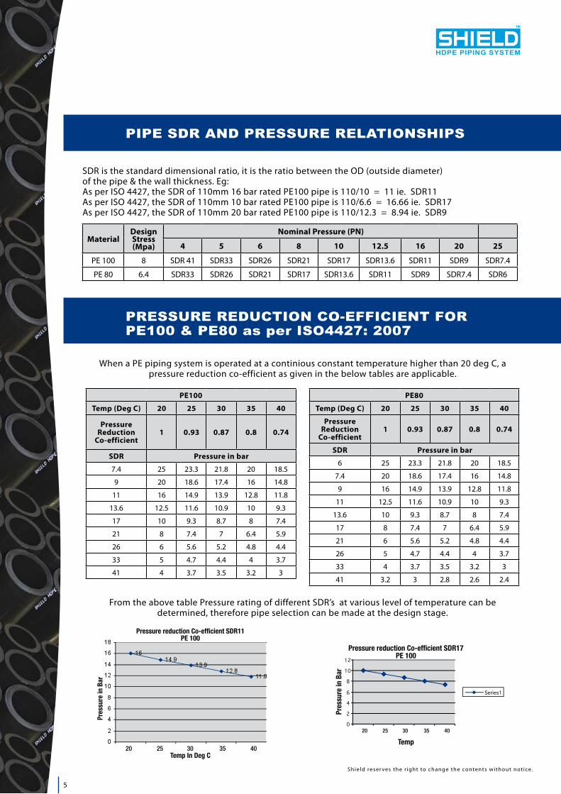
PE100
Temp (Deg C) 20 25 30 35 40
Pressure Reduction
Co-efficient1 0.93 0.87 0.8 0.74
SDR Pressure in bar
7.4 25 23.3 21.8 20 18.5
9 20 18.6 17.4 16 14.8
11 16 14.9 13.9 12.8 11.8
13.6 12.5 11.6 10.9 10 9.3
17 10 9.3 8.7 8 7.4
21 8 7.4 7 6.4 5.9
26 6 5.6 5.2 4.8 4.4
33 5 4.7 4.4 4 3.7
41 4 3.7 3.5 3.2 3
PE80
Temp (Deg C) 20 25 30 35 40
Pressure Reduction
Co-efficient1 0.93 0.87 0.8 0.74
SDR Pressure in bar
6 25 23.3 21.8 20 18.5
7.4 20 18.6 17.4 16 14.8
9 16 14.9 13.9 12.8 11.8
11 12.5 11.6 10.9 10 9.3
13.6 10 9.3 8.7 8 7.4
17 8 7.4 7 6.4 5.9
21 6 5.6 5.2 4.8 4.4
26 5 4.7 4.4 4 3.7
33 4 3.7 3.5 3.2 3
41 3.2 3 2.8 2.6 2.4
From the above table Pressure rating of different SDR’s at various level of temperature can be determined, therefore pipe selection can be made at the design stage.
20 25 30 35 40
20 25 30 35 40
SDR is the standard dimensional ratio, it is the ratio between the OD (outside diameter) of the pipe & the wall thickness. Eg: As per ISO 4427, the SDR of 110mm 16 bar rated PE100 pipe is 110/10 = 11 ie. SDR11As per ISO 4427, the SDR of 110mm 10 bar rated PE100 pipe is 110/6.6 = 16.66 ie. SDR17As per ISO 4427, the SDR of 110mm 20 bar rated PE100 pipe is 110/12.3 = 8.94 ie. SDR9
MaterialDesign Stress (Mpa)
Nominal Pressure (PN)
4 5 6 8 10 12.5 16 20 25
PE 100 8 SDR 41 SDR33 SDR26 SDR21 SDR17 SDR13.6 SDR11 SDR9 SDR7.4
PE 80 6.4 SDR33 SDR26 SDR21 SDR17 SDR13.6 SDR11 SDR9 SDR7.4 SDR6
PIPE SDR AND PRESSURE RELATIONSHIPS
PRESSURE REDUCTION CO-EFFICIENT FOR PE100 & PE80 as per ISO4427: 2007
Shield reser ves the r ight to change the contents without not ice.
When a PE piping system is operated at a continious constant temperature higher than 20 deg C, a pressure reduction co-efficient as given in the below tables are applicable.
6
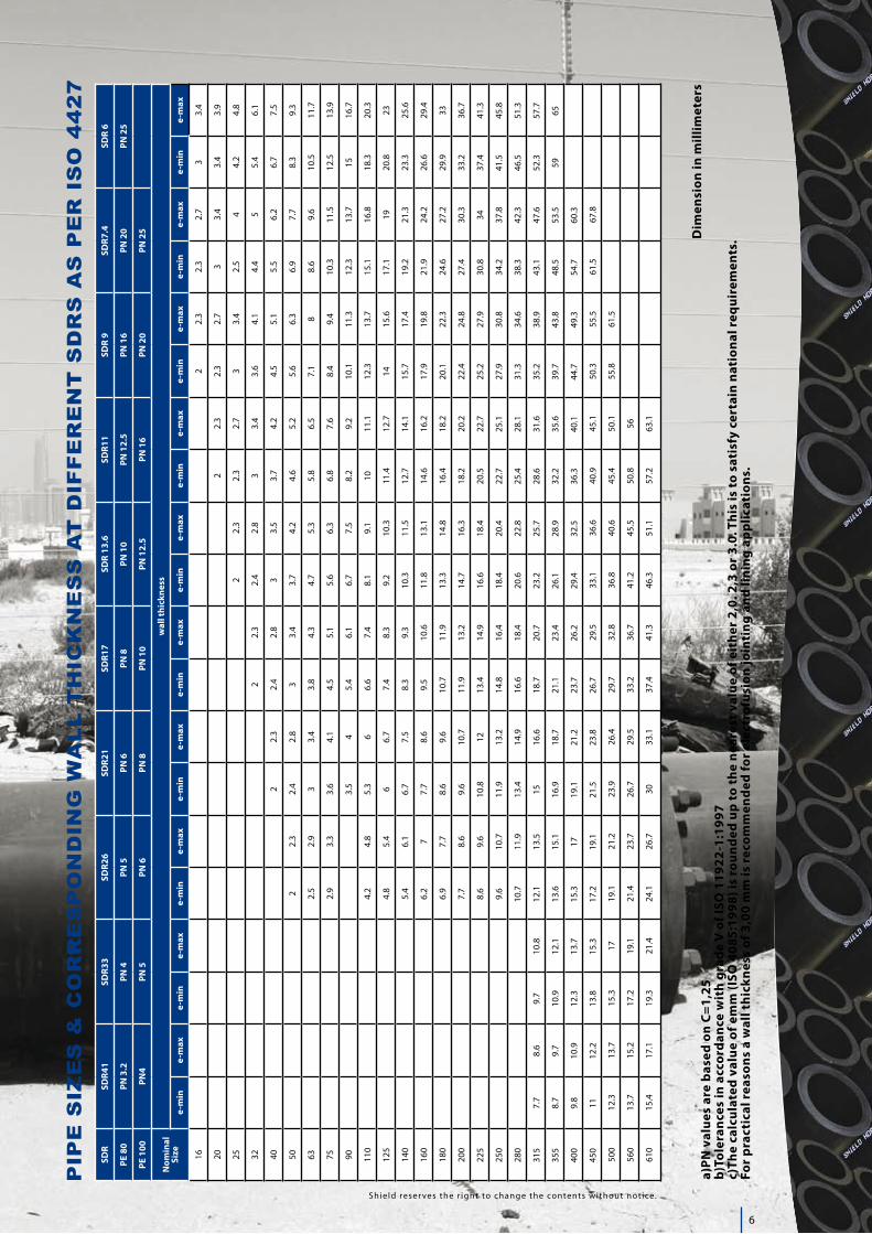
Dim
ensi
on in
mill
imet
ers
a)PN
val
ues
are
bas
ed o
n C
=1,
25b)
Tole
ranc
es in
acc
ord
ance
wit
h gr
ade
V o
f ISO
119
22-1
:199
7c)
The
calc
ulat
ed v
alue
of e
mm
(ISO
408
5:19
98) i
s ro
und
ed u
p to
the
near
est v
alue
of e
ithe
r 2,
0. 2
,3 o
r 3.
0. T
his
is to
sat
isfy
cer
tain
nat
iona
l req
uire
men
ts.
For
pra
ctic
al r
easo
ns a
wal
l thi
ckne
ss o
f 3,0
0 m
m is
rec
omm
end
ed fo
r el
ectr
ofus
ion
join
ting
and
lini
ng a
pp
licat
ions
.
PIP
E S
IZE
S &
CO
RR
ES
PO
ND
ING
WA
LL
TH
ICK
NE
SS
AT
DIF
FE
RE
NT
SD
RS
AS
PE
R I
SO
44
27
SDR
SDR4
1SD
R33
SDR2
6SD
R21
SDR1
7SD
R 13
.6SD
R11
SDR
9SD
R7.4
SDR
6
PE 8
0PN
3.2
PN 4
PN 5
PN 6
PN 8
PN 1
0PN
12.
5PN
16
PN 2
0PN
25
PE 1
00PN
4PN
5PN
6PN
8PN
10
PN 1
2.5
PN 1
6PN
20
PN 2
5
Nom
inal
Size
wal
l thi
ckne
ss
e-m
ine-
max
e-m
ine-
max
e-m
ine-
max
e-m
ine-
max
e-m
ine-
max
e-m
ine-
max
e-m
ine-
max
e-m
ine-
max
e-m
ine-
max
e-m
ine-
max
162
2.3
2.3
2.7
33.
4
202
2.3
2.3
2.7
33.
43.
43.
9
252
2.3
2.3
2.7
33.
42.
54
4.2
4.8
322
2.3
2.4
2.8
33.
43.
64.
14.
45
5.4
6.1
402
2.3
2.4
2.8
33.
53.
74.
24.
55.
15.
56.
26.
77.
5
502
2.3
2.4
2.8
33.
43.
74.
24.
65.
25.
66.
36.
97.
78.
39.
3
632.
52.
93
3.4
3.8
4.3
4.7
5.3
5.8
6.5
7.1
88.
69.
610
.511
.7
752.
93.
33.
64.
14.
55.
15.
66.
36.
87.
68.
49.
410
.311
.512
.513
.9
903.
54
5.4
6.1
6.7
7.5
8.2
9.2
10.1
11.3
12.3
13.7
1516
.7
110
4.2
4.8
5.3
66.
67.
48.
19.
110
11.1
12.3
13.7
15.1
16.8
18.3
20.3
125
4.8
5.4
66.
77.
48.
39.
210
.311
.412
.714
15.6
17.1
1920
.823
140
5.4
6.1
6.7
7.5
8.3
9.3
10.3
11.5
12.7
14.1
15.7
17.4
19.2
21.3
23.3
25.6
160
6.2
77.
78.
69.
510
.611
.813
.114
.616
.217
.919
.821
.924
.226
.629
.4
180
6.9
7.7
8.6
9.6
10.7
11.9
13.3
14.8
16.4
18.2
20.1
22.3
24.6
27.2
29.9
33
200
7.7
8.6
9.6
10.7
11.9
13.2
14.7
16.3
18.2
20.2
22.4
24.8
27.4
30.3
33.2
36.7
225
8.6
9.6
10.8
1213
.414
.916
.618
.420
.522
.725
.227
.930
.834
37.4
41.3
250
9.6
10.7
11.9
13.2
14.8
16.4
18.4
20.4
22.7
25.1
27.9
30.8
34.2
37.8
41.5
45.8
280
10.7
11.9
13.4
14.9
16.6
18.4
20.6
22.8
25.4
28.1
31.3
34.6
38.3
42.3
46.5
51.3
315
7.7
8.6
9.7
10.8
12.1
13.5
1516
.618
.720
.723
.225
.728
.631
.635
.238
.943
.147
.652
.357
.7
355
8.7
9.7
10.9
12.1
13.6
15.1
16.9
18.7
21.1
23.4
26.1
28.9
32.2
35.6
39.7
43.8
48.5
53.5
5965
400
9.8
10.9
12.3
13.7
15.3
1719
.121
.223
.726
.229
.432
.536
.340
.144
.749
.354
.760
.3
450
1112
.213
.815
.317
.219
.121
.523
.826
.729
.533
.136
.640
.945
.150
.355
.561
.567
.8
500
12.3
13.7
15.3
1719
.121
.223
.926
.429
.732
.836
.840
.645
.450
.155
.861
.5
560
13.7
15.2
17.2
19.1
21.4
23.7
26.7
29.5
33.2
36.7
41.2
45.5
50.8
56
610
15.4
17.1
19.3
21.4
24.1
26.7
3033
.137
.441
.346
.351
.157
.263
.1
Sh ie ld reser ves the r ight to change the contents without not ice.
7
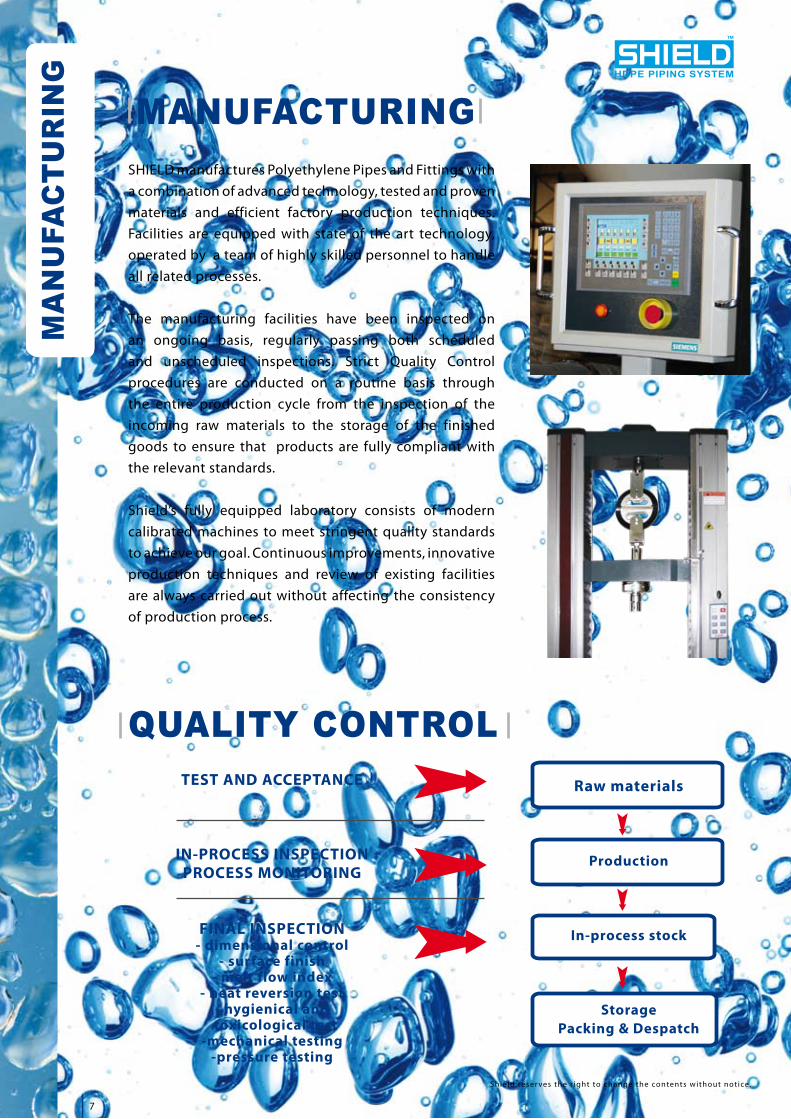
MANUFACTURING
QUALITY CONTROLTEST AND ACCEPTANCE
IN-PROCESS INSPECTIONPROCESS MONITORING
FINAL INSPECTION- dimensional control
- surface finish- melt flow index
- heat reversion test- hygienical and
toxicological test-mechanical testing
-pressure testing
Raw materials
Production
In-process stock
StoragePacking & Despatch
SHIELD manufactures Polyethylene Pipes and Fittings with a combination of advanced technology, tested and proven materials and efficient factory production techniques. Facilities are equipped with state of the art technology, operated by a team of highly skilled personnel to handle all related processes.
The manufacturing facilities have been inspected on an ongoing basis, regularly passing both scheduled and unscheduled inspections. Strict Quality Control procedures are conducted on a routine basis through the entire production cycle from the inspection of the incoming raw materials to the storage of the finished goods to ensure that products are fully compliant with the relevant standards.
Shield’s fully equipped laboratory consists of modern calibrated machines to meet stringent quality standards to achieve our goal. Continuous improvements, innovative production techniques and review of existing facilities are always carried out without affecting the consistency of production process.
Shield reser ves the r ight to change the contents without not ice.
MA
NU
FAC
TUR
ING HDPE PIPING SYSTEM

8
Design Engineers choose Shield PE100 piping system, as the system provides larger bore size because of its lower wall thickness. Moreover, at the same working pressure, designers can opt for lower SDR level pipe than in PE80 piping system.
COMPARISON OF BORE SIZE OF PE100 & PE80 AS PER ISO 4427:
Shield HDPE system offers electrofusion fittings which are easy to use and offer high performance along with a rapid, convenient method of joining with Shield polyethylene pipes. Their design ensures optimum melt pressure as the energizing coil of wire is precisely positioned to ensure uniform melting.
Each fitting displays a bar code label that enables the automatic Electro fusion control units (ECUs) to scan the barcode and determine the fusion parameters. Fittings are offered in PE100 Black or Blue & PE80 Yellow, size up to 400mm, (with larger couplers upto 710mm progressively available from the production line.)
The Long Spigot range offers a comprehensive choice of fittings suitable for Butt-Fusion. Products are offered in PE100 Black or Blue & PE80 Yellow.
Nominal Size in MM
PE100 PE80
SDR17 PN10 SDR11 PN16 SDR9 PN20 SDR13.6 PN10 SDR9 PN16 SDR7.4
PN20
50 44 40.8 38.8 42.6 38.8 36.2
63 55.4 51.4 48.8 53.6 48.8 45.8
75 66 61.4 58.2 63.8 58.2 54.4
90 79.2 73.6 69.8 76.6 69.8 65.4
110 96.8 90 85.4 93.8 85.4 79.8
125 110.2 102.2 97 106.6 97 90.8
140 123.4 114.6 108.6 119.4 108.6 101.6
160 141 130.8 124.2 136.4 124.2 116.2
180 158.6 147.2 139.8 153.4 139.8 130.8
200 176.2 163.6 155.2 170.6 155.2 145.2
225 198.2 184 174.6 191.8 174.6 163.4
250 220.4 204.6 194.2 213.2 194.2 181.6
280 246.8 229.2 217.4 238.8 217.4 203.4
315 277.6 257.8 244.6 268.6 244.6 228.8
Pipes must never be thrown from delivery vehicles or slid from the tailboard of a moving flat-bed wagon.
FITTINGS
Shield reser ves the r ight to change the contents without not ice.
HDPE PIPING SYSTEM
WATER LINESHIELD HDPE PIPING SYSTEM FOR
PIPE SELECTION
WATER
LINE
9
SL NO. DESCRIPTION RANGE SDR11 RANGE
SDR17 AVAILABLE
ELECTROFUSION FITTINGS
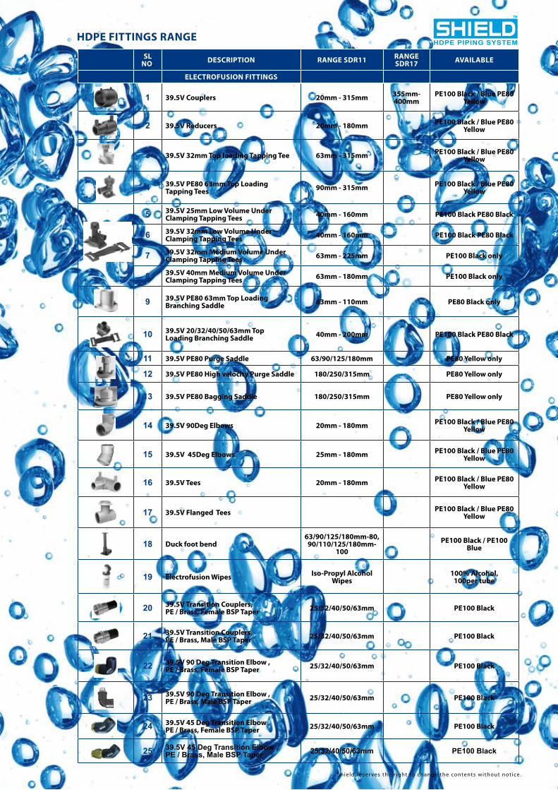
1 39.5V Couplers 20mm - 315mm 355mm- 400mm
PE100 Black / Blue PE80 Yellow
2 39.5V Reducers 20mm - 180mm PE100 Black / Blue PE80 Yellow
!
3 39.5V 32mm Top loading Tapping Tee 63mm - 315mm PE100 Black / Blue PE80 Yellow
4 39.5V PE80 63mm Top Loading Tapping Tees 90mm - 315mm PE100 Black / Blue PE80
Yellow
5 39.5V 25mm Low Volume Under Clamping Tapping Tees 40mm - 160mm PE100 Black PE80 Black
6 39.5V 32mm Low Volume Under Clamping Tapping Tees 40mm - 160mm PE100 Black PE80 Black
7 39.5V 32mm Medium Volume Under Clamping Tapping Tees 63mm - 225mm PE100 Black only
8 39.5V 40mm Medium Volume Under Clamping Tapping Tees 63mm - 180mm PE100 Black only
9 39.5V PE80 63mm Top Loading Branching Saddle 63mm - 110mm PE80 Black only
10 39.5V 20/32/40/50/63mm Top Loading Branching Saddle 40mm - 200mm PE100 Black PE80 Black
11 39.5V PE80 Purge Saddle 63/90/125/180mm PE80 Yellow only
12 39.5V PE80 High velocity Purge Saddle 180/250/315mm PE80 Yellow only
13 39.5V PE80 Bagging Saddle 180/250/315mm PE80 Yellow only
14 39.5V 90Deg Elbows 20mm - 180mm PE100 Black / Blue PE80 Yellow
15 39.5V 45Deg Elbows 25mm - 180mm PE100 Black / Blue PE80 Yellow
16 39.5V Tees 20mm - 180mm PE100 Black / Blue PE80 Yellow
17 39.5V Flanged Tees PE100 Black / Blue PE80 Yellow
18 Duck foot bend63/90/125/180mm-80,
90/110/125/180mm-100
PE100 Black / PE100 Blue
19 Electrofusion Wipes Iso-Propyl Alcohol Wipes
100% Alcohol, 100per tube
20 39.5V Transition Couplers, PE / Brass, Female BSP Taper 25/32/40/50/63mm PE100 Black
21 39.5V Transition Couplers, PE / Brass, Male BSP Taper 25/32/40/50/63mm PE100 Black
22 39.5V 90 Deg Transition Elbow , PE / Brass, Female BSP Taper 25/32/40/50/63mm PE100 Black
23 39.5V 90 Deg Transition Elbow , PE / Brass, Male BSP Taper 25/32/40/50/63mm PE100 Black
24 39.5V 45 Deg Transition Elbow , PE / Brass, Female BSP Taper 25/32/40/50/63mm PE100 Black
25 39.5V 45 Deg Transition Elbow , PE / Brass, Male BSP Taper 25/32/40/50/63mm PE100 Black
!
HDPE FITTINGS RANGE
Shield reser ves the r ight to change the contents without not ice.
HDPE PIPING SYSTEM

10
LONG SPIGOT BUTTFUSION FITTINGS
1 Reducers 20mm - 400mm 32mm- 315mm
PE100 Black / Blue PE80 Yellow
2 90Deg Elbows 20mm - 400mm 90mm- 400mm
PE100 Black / Blue PE80 Yellow
3 45Deg Elbows 25mm - 400mm 90mm- 400mm
PE100 Black / Blue PE80 Yellow
4 Tees 20mm - 400mm 90mm- 400mm
PE100 Black / Blue PE80 Yellow
5 Stub Flanges 32mm - 400mm 75mm- 400mm
PE100 Black / Blue PE80 Yellow
6 Reduced Branch Tees 63mm - 315mm 63mm- 315mm
PE100 Black / Blue PE80 Yellow
7 Flanged Branch Tees 63mm - 315mm 63mm- 315mm PE100 Black/Blue
8 All Flanged Tees 110/250/315mm PE100 Black/Blue
9 End Cap 20mm - 400mm 75mm- 400mm PE100 Black PE80 Yellow
PUPPED (EXTENDED) BUTTFUSION FITTINGS
1 Pupped Reducers 63mm - 315mm 63mm- 315mm
PE100 Black / Blue PE80 Yellow
2 Pupped 90 Deg Elbow 63mm - 355mm 90mm- 355mm
PE100 Black / Blue PE80 Yellow
3 Pupped 45 Deg Elbow 63mm - 355mm 90mm- 355mm
PE100 Black / Blue PE80 Yellow
4 Pupped Equal Tee 63mm - 400mm 90mm- 400mm
PE100 Black / Blue PE80 Yellow
5 Pupped Equal Tee, Large Diameter 450/500/630mm
PE100 Black / Blue PE80 Yellow
6 Pupped Reduced Branch Tees, Large Diameter
PE100 Black / Blue PE80 Yellow
7 Pupped Reduced Branch Tees 110mm - 355mm 110mm- 355mm
PE100 Black / Blue PE80 Yellow
8 Pupped Stub Flange Assembly, Backing ring drilled to BS4504 PN16 63mm - 630mm 90mm-
630mmPE100 Black / Blue PE80
Yellow
9 Pupped Flanged Short Branch Tees 63mm - 355mm 63mm- 355mm
PE100 Black / Blue PE80 Yellow
10 90 Deg Formed Bend 90mm - 400mm 90mm- 400mm
PE100 Black / Blue PE80 Yellow
11 45 Deg Formed Bend 90mm - 400mm 90mm- 400mm
PE100 Black / Blue PE80 Yellow
12 221/2 Deg Formed Bend 90mm - 400mm 90mm- 400mm
PE100 Black / Blue PE80 Yellow
13 11 1/4 Deg Formed Bend 90mm - 400mm 90mm- 400mm
PE100 Black / Blue PE80 Yellow
!
14 90 Deg Mitred Elbow 90mm - 400mm 90mm- 400mm
PE100 Black / Blue PE80 Yellow
15 45 Deg Mitred Elbow 90mm - 400mm 90mm- 400mm
PE100 Black / Blue PE80 Yellow
16 221/2 Deg Mitred Bend 90mm - 400mm 90mm- 400mm
PE100 Black / Blue PE80 Yellow
17 11 1/4 Deg Mitred Bend 90mm - 400mm 90mm- 400mm
PE100 Black / Blue PE80 Yellow
HDPE FITTINGS RANGE
Shield reser ves the r ight to change the contents without not ice.
HDPE PIPING SYSTEM
11
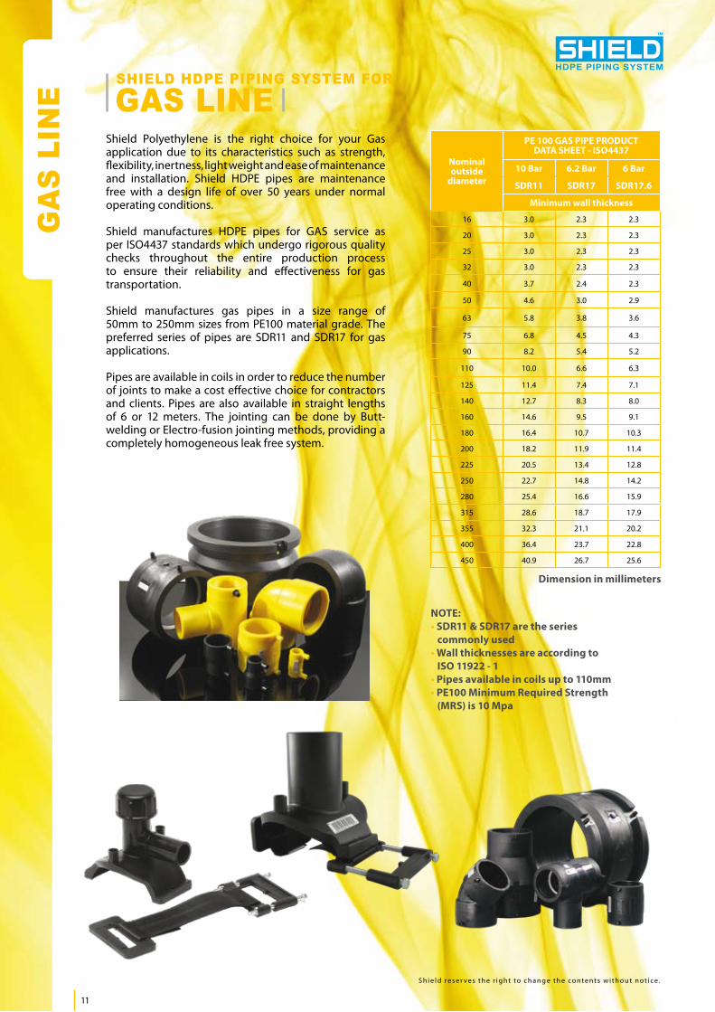
Shield Polyethylene is the right choice for your Gas application due to its characteristics such as strength, flexibility, inertness, light weight and ease of maintenance and installation. Shield HDPE pipes are maintenance free with a design life of over 50 years under normal operating conditions.
Shield manufactures HDPE pipes for GAS service as per ISO4437 standards which undergo rigorous quality checks throughout the entire production process to ensure their reliability and effectiveness for gas transportation.
Shield manufactures gas pipes in a size range of 50mm to 250mm sizes from PE100 material grade. The preferred series of pipes are SDR11 and SDR17 for gas applications.
Pipes are available in coils in order to reduce the number of joints to make a cost effective choice for contractors and clients. Pipes are also available in straight lengths of 6 or 12 meters. The jointing can be done by Butt-welding or Electro-fusion jointing methods, providing a completely homogeneous leak free system.
NOTE:• SDR11 & SDR17 are the series commonly used• Wall thicknesses are according to ISO 11922 - 1• Pipes available in coils up to 110mm• PE100 Minimum Required Strength (MRS) is 10 Mpa
Nominaloutside
diameter
PE 100 GAS PIPE PRODUCTDATA SHEET - ISO4437
10 Bar 6.2 Bar 6 Bar
SDR11 SDR17 SDR17.6
Minimum wall thickness
16 3.0 2.3 2.3
20 3.0 2.3 2.3
25 3.0 2.3 2.3
32 3.0 2.3 2.3
40 3.7 2.4 2.3
50 4.6 3.0 2.9
63 5.8 3.8 3.6
75 6.8 4.5 4.3
90 8.2 5.4 5.2
110 10.0 6.6 6.3
125 11.4 7.4 7.1
140 12.7 8.3 8.0
160 14.6 9.5 9.1
180 16.4 10.7 10.3
200 18.2 11.9 11.4
225 20.5 13.4 12.8
250 22.7 14.8 14.2
280 25.4 16.6 15.9
315 28.6 18.7 17.9
355 32.3 21.1 20.2
400 36.4 23.7 22.8
450 40.9 26.7 25.6
GAS LINESHIELD HDPE PIPING SYSTEM FOR
S h i e l d r e s e r v e s t h e r i g h t t o c h a n g e t h e c o n t e n t s w i t h o u t n o t i c e .
HDPE PIPING SYSTEM
Dimension in millimeters
GA
S LI
NE
12
FIRE LIN
E
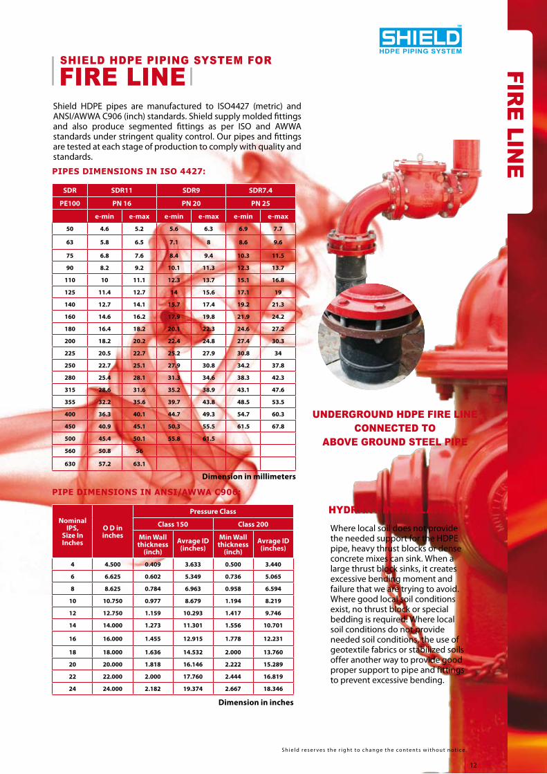
Shield HDPE pipes are manufactured to ISO4427 (metric) and ANSI/AWWA C906 (inch) standards. Shield supply molded fittings and also produce segmented fittings as per ISO and AWWA standards under stringent quality control. Our pipes and fittings are tested at each stage of production to comply with quality and standards.
Nominal IPS,
Size In Inches
O D in inches
Pressure Class
Class 150 Class 200
Min Wall thickness
(inch)Avrage ID
(inches)Min Wall
thickness (inch)
Avrage ID (inches)
4 4.500 0.409 3.633 0.500 3.440
6 6.625 0.602 5.349 0.736 5.065
8 8.625 0.784 6.963 0.958 6.594
10 10.750 0.977 8.679 1.194 8.219
12 12.750 1.159 10.293 1.417 9.746
14 14.000 1.273 11.301 1.556 10.701
16 16.000 1.455 12.915 1.778 12.231
18 18.000 1.636 14.532 2.000 13.760
20 20.000 1.818 16.146 2.222 15.289
22 22.000 2.000 17.760 2.444 16.819
24 24.000 2.182 19.374 2.667 18.346
PIPE DIMENSIONS IN ANSI/AWWA C906:
Where local soil does not provide the needed support for the HDPE pipe, heavy thrust blocks or dense concrete mixes can sink. When a large thrust block sinks, it creates excessive bending moment and failure that we are trying to avoid. Where good local soil conditions exist, no thrust block or special bedding is required. Where local soil conditions do not provide needed soil conditions, the use of geotextile fabrics or stabilized soils offer another way to provide good proper support to pipe and fittings to prevent excessive bending.
HYDRANT INSTALLATION
SDR SDR11 SDR9 SDR7.4
PE100 PN 16 PN 20 PN 25
e-min e-max e-min e-max e-min e-max
50 4.6 5.2 5.6 6.3 6.9 7.7
63 5.8 6.5 7.1 8 8.6 9.6
75 6.8 7.6 8.4 9.4 10.3 11.5
90 8.2 9.2 10.1 11.3 12.3 13.7
110 10 11.1 12.3 13.7 15.1 16.8
125 11.4 12.7 14 15.6 17.1 19
140 12.7 14.1 15.7 17.4 19.2 21.3
160 14.6 16.2 17.9 19.8 21.9 24.2
180 16.4 18.2 20.1 22.3 24.6 27.2
200 18.2 20.2 22.4 24.8 27.4 30.3
225 20.5 22.7 25.2 27.9 30.8 34
250 22.7 25.1 27.9 30.8 34.2 37.8
280 25.4 28.1 31.3 34.6 38.3 42.3
315 28.6 31.6 35.2 38.9 43.1 47.6
355 32.2 35.6 39.7 43.8 48.5 53.5
400 36.3 40.1 44.7 49.3 54.7 60.3
450 40.9 45.1 50.3 55.5 61.5 67.8
500 45.4 50.1 55.8 61.5
560 50.8 56
630 57.2 63.1
PIPES DIMENSIONS IN ISO 4427:
S h i e l d r e s e r v e s t h e r i g h t t o c h a n g e t h e c o n t e n t s w i t h o u t n o t i c e .
UNDERGROUND HDPE FIRE LINE CONNECTED TO
ABOVE GROUND STEEL PIPE
HDPE PIPING SYSTEM
FIRE LINESHIELD HDPE PIPING SYSTEM FOR
Dimension in millimeters
Dimension in inches
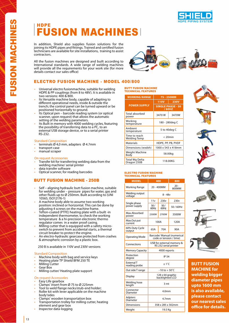
• Self – aligning hydraulic butt fusion machine, suitable for welding under – pressure pipes for water, gas and other fluids up to Ø 250mm. Built according to (UNI 10565, ISO12176-1) • A machine body able to assume two working position: inclined or horizontal. This can be done by adjusting 4 screws on the machine frame.• Teflon-coated (PTFE) heating plate with a built -in independent thermometer, to check the working temperature & a hi-precision electronic thermo regulator comes in a water proof casing.• Milling cutter that is equipped with a safety micro- switch to prevent from accidental starts, a thermal circuit breaker to protect the engine.• An electro-hydraulic gearcase protected from crashes & atmospheric corrosion by a plastic box. 250 B is available in 110V and 230V versions
Standard Composition• Machine body with bag and service keys• Heating plate TP Shield BFM 250 TE• Milling Cutter• Gear Box• Milling cutter/ Heating plate support
On request Accessories• Easy Life gearbox• Clamps’ insert from Ø 75 to Ø 225mm• Tool to weld flange necks/stub-end holder;• Roller kit with lever applicable on the machine body’sides• Clamps’ wooden transportation box• Transportation trolley for milling cutter, heating element and gear box• Inspector data-logging
BUTT FUSION MACHINE for welding bigger diameter pipes upto 1600 mm is also available, please contact our nearest sales office for details.
FUSI
ON
MAC
HIN
ES
• Universal electro fusionmachine, suitable for welding HDPE & PP couplings (from 8 to 48V). It is available in two versions: 400 & 800.• Its Versatile machine body, capable of adapting to different operational needs, inside & outside the trench; the control panel can be turned upward or be positioned horizontally to ground.• Its Optical pen – barcode reading system (or optical scanner, upon request) that allows the automatic setting of the welding parameters.• Its Built in memory with 4000 welding cycles, featuring the possibility of transferring data to a PC, to an external USB storage device, or to a serial printer RS-232.
Standard Composition• terminals Ø 4,0 mm, adapters Ø 4.7mm• transport case• manual scraper
On request Accessories• Transfer kit for transferring welding data from the welding machine/ serial printer• data transfer software• Optical scanner, for reading barcodes
ELECTRO FUSION MACHINE - MODEL 400/800
BUTT FUSION MACHINE - 250B
WORKING RANGE 75 - 250MM
POWER SUPPLY110V 230V
SINGLE PHASE - 50 / 60HZ
Total absorbed power 3470 W 3470W
Working temperature 180 - 280deg C
Ambient temperature 5 to 40deg C
Time to reach Welding Temp < 20min
Materials HDPE, PP, PB, PVDF
Dimensions (wxdxh) 1000 x 543 x 418mm
Weight Machine Body 58.00kg
Total Wg Delta Dragon 250B 118.00KG
MODEL 400 800
Working Range 20 - 400MM 20 - 800MM
Welding output voltage 8 - 48v
Single phase power supply
11v 230v 230v
50 / 60Hz
50 / 60Hz 50 / 60Hz
Max.Absorbed power 2500W 2700W 3500W
Max.Out put current 100A 120A
60% Duty Cycle output 65A 70A 90A
Operating Mode Barcode/ Manual (numerical code or tension / time)
Connections USB for external memory & RS 232 serial printer
Memory Capacity 4000 reports
Protection degree IP 54
External T reading probe ± 1˚C
Out side T range –10 to + 50˚C
Display 128 x 64 graphic backlighted LCD
Welding hose length 3 mt
Connector Diameter 4.0mm
Adpters Diameter 4.7mm
Dimensions 358 x 285 x 302mm
Weight 19.5 Kg
FUSION MACHINESHDPE
In addition, Shield also supplies fusion solutions for the joining its HDPE pipes and fittings. Trained and certified fusion technicians are available for site installations, training to assist contractors.
All the fusion machines are designed and built according to International standards. A wide range of welding machines will provide all the requirements for your work site (for more details contact our sales office)
13
HDPE PIPING SYSTEM
BUTT FUSION MACHINETECHNICAL FEATURES
ELECTRO FUSION MACHINE TECHNICAL FEATURES
ANSI American National Standard InstituteASTM American Society for Testing & Materials BS British Standard DIN Deutsche IndustrieNormenISO International Standard Organization ABS Acrylonnitrile Butadien Styrene PVC-U Polyvinyl Chloride PVC-C Polyvinyl Choliride Chlorinated PP Polypropylene, heat stabilized PE PolyethylenePVDF Polyvinylidene Fluoride EPDM Ethylene Propylene RubberGP Gross Pack
FPM Fluoric Rubber NBR Nitrile RubberG Pipe Thread R Taper Male Thread PTFE Polytetrafluorethylene Rp Parallel Female Thread PB Polybutylene E Wall Thickness PBTP Polybutylene Terephthalate® Registered Trade Mark St Steel DVS German Association of Welding d Pipe Outside Diameter
LI S T O F AB B R E V IATI O N S
KRV Plastic piping Association SDR Standard Diamentional RatioWIS Water Industry Specification S Pipe Category IGN Information & Guidence Note Water IndustryFM Fusion Method/ Factory MutualDN Nominal Diameter PN Nominal Pressure Kg Weight In Kilogram g Weigth In GramSP Standard PackMpa Mega PascalPsi Pounds per square inch
POLYETHYLENE RANGE IS DESIGNED TO COMPLY WITH THE REQUIREMENTS OF ONE OR MORE OF THE STANDARDS:
GENERAL STANDARDSISO 161-1:1996 Thermoplastic Pipes – Nominal Outside diameters & Nominal pressures metric series.ISO 4065:1996 Thermoplastic Pipes-Universal Wall Thickness tables.BS ISO11922-1:199 Thermoplastic pipes for the conveyance of fluids dimensions and tolerances metric series.BS 6437:1984 Polyethylene Pipes (type50) in metric diameters for general purposes.BS EN 1092-1:2007 Flanges and their joints – Circular flanges for pipes, valves, fittings and accessories, PN designated steel flanges. RELEVANT STANDARDS IN THE PE PIPE MODEL FOR WATER & GAS
ISO 4427-1,2,3,5 (2007-08) PE pipes and fittings for water supply- General, Pipes, Fittings, Fitness of systemISO4437 (2007-06) Buried polyethylene(PE) pipes for the supply of Gaseous fuels-Metric seriesBS EN 15494:2003 Specifications for polyethylene components and systemsBS EN12201:2003 Plastic Piping for water supply- PolyethyleneBS EN 805:2000 Water supply – requirements for systems and components outside buildingsBS EN 681-2:2000 Elastomeric seals. Material requirements for pipe joint seals used in water and drainage applications. Thermoplastic elastomers.BS 5306:1990-Part2 Fire extinguishing installations and equipment on premisesBS EN ISO8085:2001-1 Polyethylene fittings for use PE pipes for the supply of gaseous fuelsBS EN ISO8085:2001-2 Spigot fittings for buttfusion or socket fusion using heated tools and for use with electrofusion fittingsBS EN ISO8085:2001-3 Electrofusion fittingsBS EN1555:2002 Plastic piping systems for supply of gaseous fuels- polyethyleneBS EN682:2002 Elastomeric seals- Materials for seals used in pipes and fittings carrying gas and hydrocarbon fluidsDIN 8074:1999 Pipesof high density polyethylene(HDPE) type 2- dimensionsDIN 8075:1999 Pipesof high density polyethylene(HDPE) type 2- testingDIN 16963:1980 Part-1 High density polyethylene (HDPE) fittings dimensions, type 2DIN 3543-4:1984-08 High density polyethylene (HDPE) tapping valves for HDPE pipesIGN 4-08-01:1994 Bedding & sidefill materials for buried pipelinesISO 12176-1,2,3,4 Plastic pipes and fittings-Equipment for fusion jointing-Buttfusion, Electrofusion,Operators badge, Traceability codingISO 13477/78/79/80 Thermoplastic pipes for conveyance of fluids- Determination of resistance to rapid crack propagation- Small scale steady state test, Full scale test, Test method for slow crack growth on notched pipes(notch test), Resistance to slow crack Growth- Cone test methodWIS 4-08-02:1994 Specification for bedding and sidefill materials for buried pipelinesWIS 4-24-01:1998 Specification for mechanical fittings and joints including flanges for polyethylene pipes for the conveyance of cold potable water for the size range 90 to 1000 including those made of metal or plastics or a combination of bothWIS 4-32-08:2002 Specification for the fusion jointing of polyethylene pressure pipeline systems using PE80 &PE100 materialsWIS 4-32-14:1995 Specification for PE80&PE100 electro fusion fittings for nominal sizes up to and including 630 WIS 4-32-15:1995 Specification for PE80&PE100 spigot fittings for nominal sizes up to and including 1000WIS 4-32-16:1998 Specification for Butt fusion jointing machinesWIS 4-32-17:2001 Polyethylene pressure pipes for pressurized water supply and sewerage duties
S h i e l d r e s e r v e s t h e r i g h t t o c h a n g e t h e c o n t e n t s w i t h o u t n o t i c e .
HDPE PIPING SYSTEM
For further information please contact your nearest office:
UNITED KINGDOM 29th Floor, Regus Suite• One Canada Square • Canary Wharf, London Email: [email protected] Tel: + 44 (0) 207 712 1722 •+ 44 (0) 870 734 5578 •Fax: + 44 (0) 870 734 5579MIDDLE EAST & AFRICA Jebel Ali Free Zone •DUBAI U.A.E Email: [email protected]: + 971 (4) 881 2070 •Fax: + 971 (4) 881 2198