fire hydrant system - indian institute of …respark.iitm.ac.in/downloads/iitmrp-fire pumps...
TRANSCRIPT

Construction of New Buildings for IIT
Madras Research Park – Phase – II, SH: -
Fire fighting works – Supply, Installation,
testing and commissioning of pumps and
piping for firefighting system works
Technical Specifications Page 1 of 22
FIRE HYDRANT SYSTEM
1.0 Scope of work
1.1 The scope of work shall cover supply, installation, testing and commissioning of the
fire hydrant system covering the following:
a) Fire pumps, electric or diesel driven as shown in the data sheets and drawings.
b) Booster pumps at terrace or jockey pump, electric driven as shown in the data
sheets and drawings.
c) Hydrant mains, external ring and yard hydrants.
d) Wet risers in the building as specified and shown on drawings.
e) Landing valves, hose reels, hose cabinets etc.
f) Fire brigade breaching, Siamese connections and connections to pumps and
appliances.
2.0 Standards
2.1 The fire hydrant installation shall conform to and meet with the requirements set out
by the following:
1) IS: 13039-1991 Code of practice for External Hydrant
System – Provision & Maintenance
2) IS: 13716-1993 Code of Practice for Fire Safety in Hotels
3) IS: 3844-1989 Code of practice for installation of internal
fire hydrants and hose reel on premises.
4) Fire Insurance Association of India-Tariff Advisory Committee rules & guidelines.
5) Compliance with the local fire brigade and the fire enforcing authorities.
3.0 Fire Pump
3.1 The fire pump shall be multistage single or double suction centrifugal type with split
casing and direct driven by electric motor or diesel engine as specified. The pump
rating and performance shall conform to the data sheet and meet the TAC duty
requirements.

Construction of New Buildings for IIT
Madras Research Park – Phase – II, SH: -
Fire fighting works – Supply, Installation,
testing and commissioning of pumps and
piping for firefighting system works
Technical Specifications Page 2 of 22
3.2 Pump casing shall be of close-grained cast iron with bronze impeller. The shaft sleeve
shall be S.S. 304 and the trim shall be brass or bronze.
3.3 Pump shall be capable of delivering 150% of the rated capacity at 65% of the rated
head and the no-delivery head shall be not more than 140% (150% in case of end
suction type) of he rated delivery head. The pump casing shall withstand 1.5 times the
no-delivery pressure or 2 times of the duty pressure whichever is higher.
3.4 The pump shall be either electrically driven or diesel driven with direct flexible
coupling.
3.5 The electric drive motor shall be squirrel cage induction conforming to IS 325 – 1996
and rated for continuous duty (S1). Motor shall have not less than class B insulation
and minimum enclosure of IP22. The starter shall be air-cooled fully automatic star
delta or autotransformer type. Starters shall conform to IS 8544 -1977 and rated for
AC-3 duty. Starter panel shall include an Ammeter with selector.
3.6 Drive motor rating shall be based on the largest of the following:
1) Rated pump discharge at rated head
2) 150% of rated discharge @ 65% of rated head
3) Maximum poser absorbed by the pump in its operating range i.e. no-delivery to
free discharge.
3.7 The diesel engine shall be naturally aspirated (non-tubocharged) and electrically
started. The engine shall have a speed governor to regulate the rated rpm within 5%
of its rated speed. The engine shall be complete with starting batteries full-wave
selenium rectifier charger, isolator, leads, mounting frame etc. engine rating shall be
same as for the electric motor and meet with the performance requirements of IS
10002 – 1981.
3.8 Engine exhaust pipe shall have a residential duty silencer and insulated with 100 thick
48 kg/m3 fiberglass finished with 0.5mm thick aluminum cladding. The exhaust shall be
left outside the building as shown in the drg. or as directed.
3.9 A 250 lit. Day tank with necessary feed piping shall be provided. The day tank shall be
complete with mounting frame, valved inlet connection with float, overflow, gauge
glass and drain. Engine starting system shall be complete with a storage battery,
cranking motor, fuel solenoid valves, battery leads etc.
3.10 The engine shall have a remote radiator with necessary pipe and electrical connection.
The radiator shall be located outside the pump room at a distance not more than 6m
unless shown otherwise in the drawings.
Construction of New Buildings for IIT
Madras Research Park – Phase – II, SH: -
Fire fighting works – Supply, Installation,
testing and commissioning of pumps and
piping for firefighting system works
Technical Specifications Page 3 of 22
4.0 Accessories
4.1 The fire and jockey pumps shall be complete with the following accessories:
Suction and discharge eccentric reducers.
Pump coupling guard.
Common base frame, fabricated mild steel or cast iron.
4.2 Each pump shall have independent set of pressure switches. The pressure switch shall
be snap action SP DT switch rated 10A @ 220V operated through a stainless steel
diaphram. The switch shall have a pointer for manual adjustment of set point, and all
electrical connections shall be terminated in a screwed terminal connector. The entire
unit shall be encased in a cold drawn steel IP 55 enclosure. The diaphram shall be
designed for a maximum operating pressure of the system. Each pressure switch shall
be provided with a pressure gauge in parallel as shown on the drawings and all gauges
and pressure switches shall be mounted in an instrument panel with necessary control
piping and drainage facility.
4.3 Flow switches shall be paddle type SPDT snap acting contacts rated 10A @ 220V. The paddle shall be made of either brass or phosphor bronze terminated in a screwed terminal connector. The entire unit shall be encased in cold drawn steel IP 55 enclosure and the maximum operating pressure of the parts in contact with the liquid shall be consistent with the system pressure.
4.4 Shut off valves, wherever required, shall be provided with a tamper micro switch 2A @220V with necessary bracket suitable for the valve concerned.
5.0 System Operation and Control Panels
5.1 The fire pump shall be started automatically on loss of pressure and the operation
sequence of the booster and fire pumps shall be as follows:
i) Booster or jockey pump shall start when the system pressure drops by 0.5 Kg/cm2
and stop when the system pressure is re-established.
ii) The fire pump shall start when the system pressure drops by 1.0 Kg/cm2 and shall continue to run till manually switched off.
iii) Booster/jockey and fire pump starting shall be indicated on the panel with a red
indication lamp. It should also be indicated on the FACP.
Construction of New Buildings for IIT
Madras Research Park – Phase – II, SH: -
Fire fighting works – Supply, Installation,
testing and commissioning of pumps and
piping for firefighting system works
Technical Specifications Page 4 of 22
5.2 The motor starters (direct on line or star-delta) shall consist of electrically actuated contactors. The starter shall be complete with ON-OFF push buttons, timers and auxiliary contacts and shall be fully automatic. There shall be an indicating lamp with each of the pumps and an ammeter and selector switch with the fire pumps. Fire pump starting shall be annunciated through an electric siren and the pump shall be capable of being started remotely.
5.3 The starter along with isolator shall be housed in a 2.0mm M.S. box duly rust inhibited through a process of degreasing and phosphating.
5.4 All cabling to starter and control switches shall be carried out through armoured PVC FRLS cables of approved makes. Cables shall be laid in accordance with section “M V CABLING”. Cabling from starter or switch to the motor shall be through LAPP steel braided flexible of PVC FRLS cables. The pump motors and panels shall be earthed in accordance with IS 3043-1966 or as shown on drawings.
6.0 Fire Hydrants, & Hose Reels
6.1 Hydrants shall be provided internally and externally as shown on the drawings.
Internal hydrants shall be provided at each landing of and escape staircase and
additionally depending on the floor area as shown on drawings. Landing valve shall be
twin headed gun metal valve with 2-63 mm dia outlets and 100 mm inlet conforming
to IS 5290-1998. Landing valve shall have flanged inlet and instantaneous type outlets
and mounted at 1.0 m above the floor level. Instantaneous outlets for fire hydrants
shall be of standard pattern approved and suitable for 63 mm dia fire brigade hoses.
Wherever necessary, pressure reducing orifices shall be provided so as to limit the
pressure to 5.5 kg/sqcm or any other rating as required by the local fire brigade.
6.2 Internal Hydrants
6.2.1 Each landing valve shall have a hose reel cabinet of 1800 x 900 x 450 mm housing or as shown on drawings. i) Landing valve with twin 63 mm dia capped outlets and one 100 mm inlet with a
pressure gauge cock.
ii) An orifice plate (S.S. 304) assembly with flanges wherever necessary for pressure
reduction.
iii) First-aid hose reel with 30 m long 20 mm dia pressure Dunlop hose & 20 mm dia
gate valve.

Construction of New Buildings for IIT
Madras Research Park – Phase – II, SH: -
Fire fighting works – Supply, Installation,
testing and commissioning of pumps and
piping for firefighting system works
Technical Specifications Page 5 of 22
iv) 2-7.5 m long 63 mm dia flax canvas controlled percolation hoses with
instantaneous couplings.
v) One copper branch pip with bronze rings to take the nozzles at one end and fit
into the instantaneous coupling at the other.
vi) One leaded-tin-bronze nozzle of 25 mm dia.
6.2.2 The first aid hose shall conform to IS 884-1969 and be wound on a heavy duty circular hose reel with a cast iron bracket. The hose shall be permanently connected on one end to the standpipe through a 20 mm G.M gate valve with necessary hose adapter and a gunmetal nozzle at the other end. The reel shall swing out by 2700.
6.2.3 Canvas hoses shall be in two lengths of 7.5 m each, of unlined flax or controlled percolation type with instantaneous couplings, neatly rolled into bundles and held in position with steel brackets. Canvas hoses shall be tested and certified by the manufacturers, to withstand an internal water pressure of not less than 35 kg/sqcm without bursting. The hose shall also withstand a working pressure of 7 kg/sqcm without leakage or undue sweating.
6.2.4 The hose cabinet shall be fabricated from 2 mm mild steel sheet duly rust inhibited through a process of degreasing and phosphating The cabinet shall have double flap hinged doors with 4 mm clear glass and shall have necessary openings for riser main and brackets for all internals. The cabinet shall receive two coats of red oxide primer both inside and outside before two after coats of final paint of approved colour shade.
6.3 External Hydrants
6.3.1 External Hydrants shall be stand post type over-ground unless shown otherwise. All external hydrants shall be 80 mm C.I butterfly valve. Hydrants shall be located at least 2 m away from and within 15 m from the building wall.
6.3.2 Each hydrant shall be provided with a hose cabinet containing 2 x 15 m 63 dia unlined flax or controlled percolation hoses with couplings. Wherever shown, the cabinet may contain a branch pipe and nozzle. The cabinet shall be 900 x 600 x 400 fabricated out of 2 mm mild steel sheet duly rust inhibited through a process of degreasing, phosphating etc. The cabinet shall receive two coats of red oxide primer, inside and outside, before 2 coats of final painting of approved shade. The cabinet shall be wall-mounted or free standing with its own steel legs depending on the site conditions and as shown on drawings.
6.3.3 Alternatively the hoses can be centralized in hose cabinets meeting the requirements.

Construction of New Buildings for IIT
Madras Research Park – Phase – II, SH: -
Fire fighting works – Supply, Installation,
testing and commissioning of pumps and
piping for firefighting system works
Technical Specifications Page 6 of 22
6.4 The fire brigade connection shall consist of one or two twin-headed 63 mm dia gun metal
outlets with build-in check valve and drain plugs connected to a 150 mm dia outlet connection
to the water reservoir or to the hydrant main. The fire brigade collecting head shall conform
to IS 904-1983.
7.0 Piping
7.1 All piping shall be as specified under “PIPING FOR FIRE FIGHTING” and the schedule of
work for piping.
8.0 Test & Commissioning
8.1 All hydrant piping shall be tested for a hydrostatic test pressure of 20 kg/sqcm or 1.5
times the casing pressure of the pump for a period of 24 hours at the end of which
there shall be no loss in pressure
8.2 The booster & fire pump starting and stopping shall be tested by opening the test
valve and record the following:
1) Booster pump start / stop
System pressure at start up : kg/sqcm
Stop : kg/sqcm
Time elapsed from start to stop = seconds
2) Hydrant Pump start
System pressure at start up : kg/aqcm
Maintained system pressure while discharging the landing valve at the highest point.
i) pump end : kg/sqcm
ii) highest outlet : kg/sqcm
iii) intermediate points : kg/sqcm
8.3 All the operating tests shall be carried out in the presence of any local authority, Fire
Brigade or Insurance Co. Pressures obtaining at each landing valve shall be tested and
recorded. Wherever excessive pressure is recorded, the orifice plates shall be
replaced.
9.0 Makes or Materials

Construction of New Buildings for IIT
Madras Research Park – Phase – II, SH: -
Fire fighting works – Supply, Installation,
testing and commissioning of pumps and
piping for firefighting system works
Technical Specifications Page 7 of 22
9.1 All materials and equipment used shall be approved products of the Tariff Advisory
Committee and ISI stamped. The list of makes of materials below is indicative of the quality
standards expected.
a) Hydrant pumps 1) HBD
& booster pumps 2) Mather Platt
3) Beacon
b) Hydrant 1) Minimax
2) Newage
c) Rubber lined hose reel 1) Minimax
2) Dunlop
3) Any other TAC
Approved make
d) Canvas Hose 1) Minimax
2) Newage
10.0 Mode of Measurement
10.1 Hydrant pump with mounting frame, excluding concrete foundation shall be measured
per unit.
10.2 Engine driven pump complete with:
i) Mounting frame
ii) Flexible coupling
iii) Engine starter panel with starting battery charger, leads etc.
iv) Day tank
v) Exhaust pipe and insulation, silencer etc.

Construction of New Buildings for IIT
Madras Research Park – Phase – II, SH: -
Fire fighting works – Supply, Installation,
testing and commissioning of pumps and
piping for firefighting system works
Technical Specifications Page 8 of 22
vi) Remote radiator etc. as specified.
10.3 Booster pump same as Hydrant pump.
10.4 Instrument panel with pressure gauges, pressure switches, control piping, enclosure
etc. shall be measured as one unit.
10.5 Landing valves with fire hose cabinet with hose reel, rubber line hose, canvas hose,
branch pipe, axe, nozzle etc. shall be measured per unit.
10.6 External hydrant stand post type with butterfly valve or sluice valve with tailpieces,
etc. shall be measured per unit.
10.7 Fire brigade inlet connection completes with 1 or 2 nos. 63 dia twin head inlets with
non-return valve with 100 or 150 dia respectively of inlet pipe at least 1.5 m long shall
be measured per unit.
10.8 External Hose reel boxes complete with hoses and enclosure etc. shall be measured
per unit.
10.9 Control cabling from pressure gauge panel to the respective starters shall be measured in running meter and paid at unit rates. Starter and isolator for each pump housed inside the M.S box shall be measured as unit and paid.

Construction of New Buildings for IIT
Madras Research Park – Phase – II, SH: -
Fire fighting works – Supply, Installation,
testing and commissioning of pumps and
piping for firefighting system works
Technical Specifications Page 9 of 22
TECHNICAL SPECIFICATION OF FIRE PUMP PANEL
Technical Specification of New Fire Fighting Pump Panel – Cubical Type – 14 / 16 Gauge, MS CRCA
Sheet steel enclosed floor mounting Indoor Type, suitable for 3 Phase 4Wire 440 Volts, 50 Hz supply
system and complete with all interconnections in copper PVC insulated wires and Aluminium bus-bar
etc and shall be having earthing bus-bar with distinct 2 Nos. Terminal on either sides for connecting
with external earthing system. The Panel shall be comprising of the following:-
Incoming Feeder –
1 No,-- 35 KA, 400 Amps rating TPN MCCB with rotary handle having inter-locking arrangements
with doors and complete with over current and short circuit releases & having 1 Set – Metering &
indicating equipments having the following;---
1 No. Volt Meter with selector switch-- Analogue Type.
1 No. Ammeter with selector switch ----Analogue Type.
3 Nos. – 400/5 Ampsct ratio 15 VA Class 1, current Transformer tape wound bpl type.
1 Set – backup control SPMCB 4 Amps rating
1 No. – Load Manager
Bus-Bar
1 Set – 500 Amps rated TPN Aluminium Bus-bar duly PVC colour-coded heat shrinkable type PVC
sleeve.
Outgoing
i) 1 Set – 90 HP rated Star Delta Auto Manual Operating Starter Feeder for Fire Hydrant Pump
having & comprising of the following:-
1 No. – 160 Amps TPN MCCB (35 KA) with over current and short circuit releases along with
rotary handle for door interlocking.
3 Nos. – 80 Amps rated TP power contactor with 2 NO + 2 NC auxiliary contacts.
1 No. – Self rest type 45– 75 Amps rated Bi-metal over-load relay with built in single phasing
prevention.
1 No. – Electronic Timer for changeover from Star to delta operation.
1 Set – ON / OFF Push buttons.
1 Set - ON / OFF / Trip Indicating Lamps.
1 Set –Control sp MCB – 4 Amps rated
1 Set – 0-50-150 Amps Ammeter with 1 No. Current Transformer
1 No. – Auxiliary contactor for automation having 4 NO + 4 NC contacts.
1 No. – Auto manual selector switch

Construction of New Buildings for IIT
Madras Research Park – Phase – II, SH: -
Fire fighting works – Supply, Installation,
testing and commissioning of pumps and
piping for firefighting system works
Technical Specifications Page 10 of 22
1 Set – Power Terminals for outgoing power cable connection
1 Set – Control Terminals for Outgoing / Incoming control cable connections
Ii) 1 Set -- – do ----same as above for Sprinkler Pumps -90HP rated
Iii)1 Set – do as a Spare for Fire Hydrant / Sprinkler Pump
Iv)1 Set – Direct on line starter for 6HP Jockey pump comprising of the following:-
1 No. – 32 Amps rated TPN MCB
1 No. – 16 Amps rated TP contactor with 2 NO + 2 NC auxiliary contacts.
1 No. – self reset type 4.5-7.5 Amps overload relay with built-in single phasing prevention
1 Set – ON / OFF Push buttons
1 Set – ON / OFF Trip indicating lamps
1 No. – Auxiliary contactor with 4 NO + 4 NC contacts.
1 No. – Ammeter direct operating 0-10-60 Amps rated.
1 Set – Terminal Block for Power / Control Cabling
1NO-- Auto manual selector switch
V)1 Set ----– Do ---SAME AS ABOVE but for Spare Jockey Pump.
QTY----1SET
Construction of New Buildings for IIT
Madras Research Park – Phase – II, SH: -
Fire fighting works – Supply, Installation,
testing and commissioning of pumps and
piping for firefighting system works
Technical Specifications Page 11 of 22
PIPING FOR FIRE FIGHTING
1.0 Scope
1.1 The scope of work covers, supply, laying, testing and commissioning of the entire
piping system for the Fire Fighting Installation i.e. Fire Hydrant and sprinkler systems.
2.0 Standards
2.1 The following standards shall be applicable:
i) IS 1239 Mild Steel Tubes & Tubulars
And fittings
ii) IS 1879 Malleable iron fittings
iii) IS 778 Gun Metal gate, globe and
Check valves
iv) IS 1537 Vertically cast iron double
Flanged pipes
v) IS 7181 Horizontally cast double
flanged pipes.
All standards should be the latest.
3.0 Hydrant Mains
3.1 External
3.1.1 Underground external mains shall be either
a) Double Flanged class C pipes conforming to IS 7181 or to 1537 upto 300 mm dia or
7.0-kg/sqcm pressures.
b) For sizes higher than 300 mm or 7.0-kg/sqcm pressure pipes to IS 1537 shall be class C
there shall be no change in class, in respect of pipes to IS 7181.
c) Ductile iron or mild steel pipes ERW conforming to IS 1239 upto ERW pipes to IS 3589 or
BS 3601.
3.1.2 Where the cast iron double-flanged pipe diameter exceeds 300 mm and system pressure is more than 7 kg/sqcm; class C pipes shall be used. Cast iron pipes shall use only cast iron fittings conforming to IS 1538. All flange joints shall be designed for a pressure rating of 2.0

Construction of New Buildings for IIT
Madras Research Park – Phase – II, SH: -
Fire fighting works – Supply, Installation,
testing and commissioning of pumps and
piping for firefighting system works
Technical Specifications Page 12 of 22
N/sq mm and joints shall use high tensile bolts with 3mm fiber reinforced Teflon gasket. Pipes shall be given one coat of hot bitumen before being laid in position.
3.1.3 Ductile iron or mild steel pipes, when laid underground, shall be protected against corrosion by two coats of hot bitumen and two wraps of fiber glass tissue over the entire length including fittings & valves. Fittings shall be weldable wrought iron fittings suitable for butt-welding and 10% of the welded joints shall be radio graphically tested and found in order. The welded joints shall be random selected for testing in consultation with the Engineer. All flanges shall be slip-on welded flanges to IS 6392 with a 3mm fiber-reinforced Teflon gasket and rated for 2.0 N/sq mm.
3.1.4 Valves 65 mm dia and below shall be heavy duty gun metal full way gate valves or globe valves conforming to IS 778-20 Kg/sqcm class. Valves shall be tested at manufacturer’s works and ISI stamped. Sluice valves above 80 mm shall be cast iron double flanged, with rising spindle conforming to and stamped to ISI 780-20 kg class. Exposed valves shall be provided with wheel for operation and underground valves cap-tops. Contractor shall provide suitable operating keys for sluice valves with tops.
3.1.5 Underground mains shall be laid not less than 750 mm below the ground level and shall be at least 2m away from the building face and supported on concrete pedestals at every 3.5m and held on with galvanized iron clamps. Concrete thrust anchors shall be provided at all bends and tees as shown on drawing and as directed. All excavation for pipe laying shall be carried out with sufficient width for making proper joints. Backfilling shall be done only after the piping is hydro-statically pressure tested. Piping shall be constantly kept clean till tested.
3.1.6 All valves shall be housed in brick masonry chambers over 150 mm cement concrete (1:3:6) foundation. The brick walls of the chamber shall be plastered inside and outside with 20mm cement sand plaster 1:4 with a floating coat of neat cement. Chambers shall be 650 x 650 mm clear for depths upto 900 mm and 1000 x 1000 mm for depths beyond. Each chamber shall have a cast iron surface box approved by the local Fire brigade.
3.1.7 Piping laid above ground shall be supported on cement concrete (1:3:6) pedestals raising the bottom of the pipe at least 150mm over the ground level and held to the pedestals with galvanized clamps. Pedestals shall be mad at 3.0 m center to center and as shown on drawings. Cement concrete 1:3:6 thrust anchors shall be provided at all tee-off points and change of direction as shown on drawings and as required. Pipes laid on walls and ceiling shall have galvanized steel brackets.
3.2 Internal

Construction of New Buildings for IIT
Madras Research Park – Phase – II, SH: -
Fire fighting works – Supply, Installation,
testing and commissioning of pumps and
piping for firefighting system works
Technical Specifications Page 13 of 22
3.2.1 All internal pipes shall be, unless otherwise specified, heavy quality galvanized mild steel tubes to IS 1239 using wrought G.I. steel heavy-duty screwed fittings. Flanges shall be provided to mate with vales and other equipment and shall conform to IS 6392. Flanges shall be screwed type. Flanges shall be rates for 2.0 N/sqmm.
3.2.2 All fittings for sprinkler piping shall be extra heavy duty galvanized M.S. screwed type suitable for the pressure encountered in sprinkler piping. All tap-offs from vertical riser to floor piping shall have flange or union connections. All flow switched shall have flanges or unions on both sides.
3.2.3 Valves shall be as for external piping.
3.2.4 All pipes shall be of approved make and best quality without rust marks. Pipes and fittings shall be fixed in a manner as to provide easy accessibility for repair and maintenance and shall not cause obstruction in shafts, passages etc. pipes and fittings shall be fixed truly vertical horizontal or in slopes as required in a neat workmanship manner. Pipes shall be securely fixed to walls and ceilings by suitable supports at intervals specified. Only approved type of anchor fasteners shall be used for RCC ceiling and walls.
3.2.5 All pipes shall be adequately supported from ceiling or walls through structural supports fabricated from mild steel structural e.g. rods, channels, angles and flats generally as shown on drawings. Fasteners shall be shear type anchor fasteners in concrete walls and ceilings and wrought steel spikes of at least 75mm long in brick walls. All pipes supports shall be painted with 1 coats of red oxide primer and two coats of black enamel paint. Pipe supports shall be as follows:
Upto 50 mm nominal bore 1.75m
63 mm to 100 mm nominal bore 2.0 m
Over 100 mm nominal bore 2.5m
3.2.6 All low point loops in the piping shall be provided with 25mm gun metal full-way valves with rising spindle for draining the system. All valves shall have screwed brass caps. Likewise 25mm gunmetal air vents shall be provided at all high point loops t prevent air locking.
3.2.7 All piping shall have flanged joints at about 25m intervals to facilitate easy maintenance.
3.3 Painting

Construction of New Buildings for IIT
Madras Research Park – Phase – II, SH: -
Fire fighting works – Supply, Installation,
testing and commissioning of pumps and
piping for firefighting system works
Technical Specifications Page 14 of 22
3.3.1 All exposed piping for fire fighting shall be distinctly painted ‘Fire Red’ shade 536 to IS:5-1978.
Pipes shall first receive two coats of red oxide primer uniformly applied and two coats of oil
paint applied thereafter. All pipes supports shall be painted black as specified for support &
clamps.
4.0 Testing & Commissioning
4.1 All piping after installation shall be tested for a hydrostatic test pressure of 20 Kg/Sqcm
maintained for 24 hours. All joints and valves shall be checked for leaks and rectified and
retested. During testing all valves except drain & air valves shall be kept fully open.
5.0 Makes of Materials
5.1 The following makes of materials are listed as conforming to the specifications.
Cast Iron Pipes 1) Indian Iron & Steel
2) Kesoram
3) Electrosteel castings
Galvanized Steel Pipes 1) Indian Tube (Tata)
2) Zenith
3) Gujarat Steel Tube
4) B.S.T/Apollo Steel Tubes
Fittings 1) RM Engineering Works Ahmedabad
2) KS Engineering Works Ghaziabad
Valves 1) Leader
2) Kirloskar
3) G.G. (Bombay Metals & Alloys)
6.0 Mode of Measurement
6.1 All external piping shall be measured along the center line of the pipe and paid per unit length
and shall include:
i) All Pipes & Fittings
ii) Bituminous coating
Construction of New Buildings for IIT
Madras Research Park – Phase – II, SH: -
Fire fighting works – Supply, Installation,
testing and commissioning of pumps and
piping for firefighting system works
Technical Specifications Page 15 of 22
6.2 All internal piping shall be measured similarly but shall include for the pipe supports and clamps instead of excavation.
6.3 All valves, air valves, drain valves together with flanges or tail pieces shall be measured per unit.
6.4 All excavation and concrete supports and thrust blocks shall be measured as per drawing and paid for per cum.
Construction of New Buildings for IIT
Madras Research Park – Phase – II, SH: -
Fire fighting works – Supply, Installation,
testing and commissioning of pumps and
piping for firefighting system works
Technical Specifications Page 16 of 22
PIPE SUPPORTS
1.0 Pipe Supports
1.1 All water supply and drain pipes whether horizontal or vertical shall be suitably supported using galvanized M.S clamps or Hitech brackets, angles etc. manufactured by M/s. Hitech Supports (India) Pvt. Ltd or equivalent.
1.2 Vertical Pipes
1.2.1 The pipes running vertical inside shaft shall be supported by galvanized M.S angles fixed to wall with anchor bolts and studs. The clamps shall be provided at every 3000 mm c/c or as specified in the table.
1.2.2 When the horizontal distance between the center lines of two adjacent pipes is less than 300mm a powder coated HITECH rail shall be fixed to the wall. The pipes independently clamped to the rail with ‘U’ bolt clamps.
1.3 Horizontal Pipes
1.3.1 Pipes running horizontal shall be supported from structural beam / slab by using appropriate galvanized M.S pipe hangers, double angles etc. of HITECH or equivalent make.
1.3.2 The spacing of supports shall be as follows: ______________________________________________________________________
GI PIPES / M.S PIPES CI SPUN PIPES
______________________________________________________________________
Internal Spacing Internal Spacing
Dia (mm) (mm) Dia (mm) (mm)
______________________________________________________________________

Construction of New Buildings for IIT
Madras Research Park – Phase – II, SH: -
Fire fighting works – Supply, Installation,
testing and commissioning of pumps and
piping for firefighting system works
Technical Specifications Page 17 of 22
15 1800 75 – 150 2700
20 – 25 2400 200 – 250 3000
32 2700 300 3600
40 – 50 3000
65 – 80 3600
100 4000
150 4500
______________________________________________________________________
1.3.3 Supports for horizontal piping longer than 15m in a stretch shall be provided with swivel clamps. Otherwise, the clamps shall be universal clamps or rigid clamps as required by the Project Engineer.
1.3.4 When the centre line distance of two adjacent pipes is less than 300mm a horizontal rail common for the pipes shall be provided on slab / beam and the pipes clamped to this rail with clamps as in 1.3.3 above.
1.4 Fixing of clamps / rails etc
1.4.1 All clamps, rails and accessories shall be fixed to the structure (beam, slab, walls etc) by using approved good quality anchor fasteners of appropriate size.
1.5 Mode of Measurement
1.5.1 The cost of pipe supports described above forms part of the rate quoted for piping and no
extra shall be payable on the account.

Construction of New Buildings for IIT
Madras Research Park – Phase – II, SH: -
Fire fighting works – Supply, Installation,
testing and commissioning of pumps and
piping for firefighting system works
Technical Specifications Page 18 of 22
PAINTING
1.0 Scope
1.1 The scope of work covers painting of:
1) All equipment 2) Piping & pipe supports 3) Duct supports 4) Electric Panels & cable trays
1.2 All equipment and piping in accordance with the following colour code (or other colours if specifically requested for by the Engineer-in-charge)
Equipment / Service
Colour
Band
Width
(mm)
Spacing
(mm)
Colour
Cold Water
Municipal Seagreen - - -
Domestic Seagreen 25 1500 White
Flush Seagreen 25 1500 Brown
Hotwater Supply Seagreen 25 1500 Red
Hotwater Ret Seagreen 25 1500 Red (chain
dotted)
Drainage Black
Soil Black - - -
Waste Black 25 1500 White
Vent Black 25 1500 White (chain
dotted)
Rain Water Black - -

Construction of New Buildings for IIT
Madras Research Park – Phase – II, SH: -
Fire fighting works – Supply, Installation,
testing and commissioning of pumps and
piping for firefighting system works
Technical Specifications Page 19 of 22
Oils
HSD Light Brown - - -
LDO Light Brown 25 1500 White
Light Brown 25 1500 White & Blue
Natural Gas
Equipment / Service
Colour
Band
Width
(mm)
Spacing
(mm)
Colour
Pumps & Motors Canary Yellow - - -
Supports Black or as directed - - -
2.0 All surfaces to be painted shall be thoroughly cleaned with wire brush to remove completely
rust and other extraneous substances. Over the cleaned surfaces one coat or red oxide primer
shall be applied completely covering the exposed surfaces. Out finish coat of painting shall be
applied one day after the prime coat, after ensuring that the paint is dry. The second coat shall
be done before the installation is handed over and after approval to do so from the Engineer-
in-charge.
3.0 Mode of measurement
3.1 All painting shall form part of the cost (Item Rate) of equipment, piping etc. No separate payment shall be admissible.
Construction of New Buildings for IIT
Madras Research Park – Phase – II, SH: -
Fire fighting works – Supply, Installation,
testing and commissioning of pumps and
piping for firefighting system works
Technical Specifications Page 20 of 22
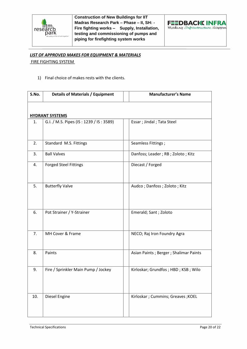
LIST OF APPROVED MAKES FOR EQUIPMENT & MATERIALS
FIRE FIGHTING SYSTEM
1) Final choice of makes rests with the clients.
S.No. Details of Materials / Equipment Manufacturer’s Name
HYDRANT SYSTEMS
1. G.I. / M.S. Pipes (IS : 1239 / IS : 3589) Essar ; Jindal ; Tata Steel
2. Standard M.S. Fittings Seamless Fittings ;
3. Ball Valves Danfoss; Leader ; RB ; Zoloto ; Kitz
4. Forged Steel Fittings Diecast / Forged
5. Butterfly Valve Audco ; Danfoss ; Zoloto ; Kitz
6. Pot Strainer / Y-Strainer
Emerald; Sant ; Zoloto
7. MH Cover & Frame NECO; Raj Iron Foundry Agra
8. Paints Asian Paints ; Berger ; Shalimar Paints
9. Fire / Sprinkler Main Pump / Jockey Kirloskar; Grundfos ; HBD ; KSB ; Wilo
10. Diesel Engine Kirloskar ; Cummins; Greaves ;KOEL

Construction of New Buildings for IIT
Madras Research Park – Phase – II, SH: -
Fire fighting works – Supply, Installation,
testing and commissioning of pumps and
piping for firefighting system works
Technical Specifications Page 21 of 22
11. Motor ABB; Kirloskar; Siemens
12. Mechanical Seal Burgmann
13. Couplings Lovejoy
14. Anti Vibration Mounting Dunlop; Kanwal Industrial Corporation;
Resistroflex
15. Pressure Switch Indfoss ; System Sensor
16. Pressure Gauge Fiebig ; H Guru
17. Water Flow Switch
Rapid Control ; System Sensor
Spray Safe
18. Pipe Protection Wrapping IWL ; Rustech
19. Electronic Level Indicator Auto Pump ; Techtrol ; Minilec ; Pumptcol
20. Welding Rods ADOR; Cosmos; ESAB
21. Fastner Fisher; Hilti

Construction of New Buildings for IIT
Madras Research Park – Phase – II, SH: -
Fire fighting works – Supply, Installation,
testing and commissioning of pumps and
piping for firefighting system works
Technical Specification Page 22 of 22