fire performance of escape stairs - jeld-wen.co.uk uk - fire... · of issues including fire spread,...
TRANSCRIPT

Fire Performance of Escape StairsBD 2569
www.communities.gov.ukcommunity, opportunity, prosperity

Fire Performance of Escape StairsBD 2569
October 2009Department for Communities and Local Government

Department for Communities and Local GovernmentEland HouseBressenden PlaceLondon SW1E 5DUTelephone: 020 7944 4400Website: www.communities.gov.uk
© Crown Copyright, 2009
Copyright in the typographical arrangement rests with the Crown.
This publication, excluding logos, may be reproduced free of charge in any format or medium for research, private study or for internal circulation within an organisation. This is subject to it being reproduced accurately and not used in a misleading context. The material must be acknowledged as Crown copyright and the title of the publication specified.
Any other use of the contents of this publication would require a copyright licence. Please apply for a Click-Use Licence for core material at www.opsi.gov.uk/click-use/system/online/pLogin.asp, or by writing to the Office of Public Sector Information, Information Policy Team, Kew, Richmond, Surrey TW9 4DU
e-mail: [email protected]
If you require this publication in an alternative format please email [email protected]
Communities and Local Government PublicationsTel: 030 0123 1124Fax: 030 0123 1125
Email: [email protected] via the Communities and Local Government website: www.communities.gov.uk
October 2009
Product Code: 09SB06019
ISBN: 978 1 4098 1653 9

Contents
Executive Summary 5
Chapter 1 7Introduction and objectives
Chapter 2 8Programme of work
2.1 Test matrix 92.2 Test 1 (sample 1) 122.3 Test 2 (sample 2) 192.4 Test 3 (sample 5) 232.5 Test 4 (sample 9) 252.6 Test 5 (sample 13) 312.7 Test 6 (sample 3) 342.8 Test 7 (sample 11) 352.9 Test 8 (sample 8) 372.10 Test 9 (sample 14) 382.11 Test 10 (sample 6) 422.12 Test 11 (sample 7) 462.13 Test 12 (sample 12) 492.14 Test 13 (sample 4) 512.15 Comparison of results 53
Chapter 3 58Conclusions
References 59


Executive Summary | 5
Executive Summary
This is the Final Research Report for the project ‘Fire Performance of Escape Stairs’ commissioned by Communities and Local Government and carried out by BRE. The overall aim of the project is to extend the methodology adopted in the TF2000 research project to develop guidance based on a test method that provides a realistic assessment of the fire performance of escape stairs in practice. It is intended that this approach will retain existing levels of safety with regard to means of escape and access for the Fire and Rescue Service whilst enabling alternatives to prescriptive design solutions.
The experimental programme was developed in consultation with a Steering Group of key stakeholders. In addition to BRE and Communities and Local Government, Steering Group members included regulatory bodies, the Fire and Rescue Service, insurers and manufacturers of stair products and fire retardant treatments. They provided valuable input to the project and considered a range of issues including fire spread, structural performance, design fire scenarios, stair design including geometry and material specification, and the level of fire protection required to achieve the functional requirements of the Building Regulations.
An experimental programme consisting of 13 fire tests has been conducted. The parameters investigated were stair geometry, timber used for treads and risers, the nature and level of reaction to fire treatment and the influence of floor coverings. A test methodology has been developed which has proved to be repeatable and well defined in terms of fire loading, location of the seat of the fire, ventilation conditions and ignition procedure. This report contains the test methodology, results and observations from the fire tests. The main conclusions of the experimental programme are as follows:
• Unprotectedtimberstairsareincapableofsurvivingthefirescenariousedinthe draft test procedure.
• Thereturnflightwithintermediatelanding(dog-leg)stairgeometryprovidesa worst case in relation to fire spread.
• Thestraightflightgeometryprovidesaworstcaseintermsofstructuralstability.
• Thespecimensprotectedwithanintumescentsurface-appliedtreatmentsurvived both the fire test and the post-fire structural stability test without any significant damage. There was no significant difference between the performance of the whitewood and medium density fibreboard (MDF) treads.

6 | Fire Performance of Escape Stairs
• Thespecimensprotectedwithapressureimpregnationtreatmenttoachievea notional Class 1 performance survived both the fire test and the post-fire structural stability test. For the straight flight specimen, the stair was not safe to use once the load had been removed.
• Thespecimensprotectedwithapressureimpregnationtreatmenttoachievea notional Class 0 performance survived both the fire test and the post-fire structural stability test without any significant damage.
• Theinclusionofsurfacecoveringsdidnothaveadetrimentaleffectontheperformance of the stair and did not provide a route for fire spread up the stair or between the stair and landing.
A guidance document, based on the outcome of the experimental programme, has also been produced. The guidance document contains a draft method of test and assessment with a summary of the main results from the experimental programme.

Chapter 1 Introduction and objectives | 7
Chapter 1
Introduction and objectives
This is the Final Research Report for the project ‘Fire Performance of Escape Stairs’ commissioned by Communities and Local Government and carried out by BRE.
The overall aim of the project was to extend the methodology adopted in the TF2000 research project1 to develop guidance based on a test method that provides a realistic assessment of the fire performance of escape stairs in practice. It was intended that this approach would retain existing levels of safety with regard to means of escape and access for the Fire and Rescue Service whilst enabling alternatives to prescriptive design solutions.
This report details the test methodology, results and observations from the fire tests undertaken.

8 | Fire Performance of Escape Stairs
Chapter 2
Programme of work
Five main tasks were identified to meet the project objectives, as follows.
Task 1 – Identification and engagement of stakeholdersA Steering Group of key stakeholders was established. In addition to BRE and Communities and Local Government, the Steering Group members included representatives of regulatory bodies, the Fire and Rescue Service, insurers and manufacturers of stair products and fire retardant treatments, and were as follows:
• BRE
• CommunitiesandLocalGovernment
• TheFireandRescueService(CFOA)
• TheFireBrigadesUnion(FBU)
• TheBritishWoodworkingFederation(BWF)
• TheWoodPreservativesAssociation(WPA)
• BritishGypsum
• SustainableBuildingsDivision,CommunitiesandLocalGovernment
• ScottishBuildingStandards(SBS)
• Prestoplan
• NorthernIrelandBuildingControl.
They provided valuable input to the project and considered a range of issues including fire spread, structural performance, design fire scenarios, stair design including geometry and material specification, and the level of fire protection required to achieve the functional requirements of the Building Regulations.
Three Steering Group meetings were held during the project. The Steering Group meetings and subsequent discussions and correspondence have been key to the success of the project and these contributions are gratefully acknowledged.

Chapter 2 Programme of work | 9
Task 2 – Selection and identification of potential design solutionsThe parameters to be investigated in the experimental programme were chosen following discussions in the Steering Group meetings. The critical parameters were stair geometry, timber used for treads and risers, the nature and level of reaction to fire treatment and the influence of floor coverings.
Task 3 – Develop draft test methodologyThe test methodology developed has proved to be repeatable and well defined in terms of fire loading, location of the seat of the fire, ventilation conditions and ignition procedure. Some modifications were made during the course of the project and are included in the draft test standard.
Task 4 – Experimental programme and data analysisAn experimental programme of 13 fire tests was conducted.
Task 5 – Produce guidance based on a draft standardFollowing the experimental programme, a guidance document was produced. This guidance contains a draft method of test and assessment with a summary of the main results from the experimental programme.
2.1 Test matrix
The parameters for inclusion in the experimental phase of the project were extensively debated during meetings of the project Steering Group. The test schedule is described in Table 1 and should be read in conjunction with the following notes:
Timber species for all strings, newels, handrails and spindles: whitewood, Picea abies (only risers and treads will vary – see Table 1)
Width of stairs’ overall strings 1160 mm
Timber trimmer provided with landing of 22 mm flooring
Assembly by glue and screws – cascamite adhesive to be used
Detail of nosing and tread to riser connection to suit manufacturer – design to be in accordance with Approved Document M
Approved Document M Rise: 170 mm maximum
Approved Document M Going: 280 mm
Total rise on each dog-leg: 1190 mm with 7 risers on each leg

10 | Fire Performance of Escape Stairs
Total rise on straight flight: 2380 mm with 14 risers
Pitch: 31.3 degrees
Newel posts: 90 mm square
Handrail size: 68 mm x 45 mm
Spindle size: 35 mm square
Surface treatment brush applied on site
The original plan was to conduct 14 tests. However, one of these tests was abandoned as the surface-applied coating provided only a single level (Class 0) of fire retardancy.

Chapter 2 Programme of work | 11
Tab
le 1
Tes
t mat
rix (*
incl
udes
floo
r cov
erin
g)
Sam
ple
n
o.
Test
no
.St
air
geo
met
ryTi
mb
er ty
pe/
spec
ies
Trea
ds
and
Ris
ers
Trea
tmen
t pro
cess
No
. of r
iser
s o
n e
ach
do
g-le
g
Trea
ds
wh
itew
oo
d,
Pice
a ab
ies
Gra
de
C24
(mm
)
Trea
ds
MD
F (m
m)
(min
imu
m
den
sity
720
kg
/m3 )
Ris
ers
wh
itew
oo
dPi
cea
abie
s(m
m)
Ris
ers
MD
F (m
m)
Test
dat
e
11
Dog
-leg
Whi
tew
ood
Non
e7
44
14
24/8
/07
22
Stra
ight
fli
ght
Whi
tew
ood
Non
e14
44
14
31/8
/07
36
Dog
-leg
Whi
tew
ood
1 im
preg
nate
d tr
eatm
ent t
o ac
hiev
e C
lass
1 p
erfo
rman
ce7
44
14
12/2
/08
413
Dog
-leg
Whi
tew
ood
2 im
preg
nate
d tr
eatm
ent t
o ac
hiev
e C
lass
0 p
erfo
rman
ce7
44
14
4/6/
08
53
Dog
-leg
MD
FN
one
7
44
1211
/9/0
7
610
Stra
ight
fli
ght
MD
F1
impr
egna
ted
trea
tmen
t to
achi
eve
Cla
ss 1
per
form
ance
14
44
1213
/3/0
8
711
Dog
-leg
MD
F2
impr
egna
ted
trea
tmen
t to
achi
eve
Cla
ss 0
per
form
ance
7
44
122/
06/0
8
88
Stra
ight
fli
ght
Whi
tew
ood
1 im
preg
nate
d tr
eatm
ent t
o ac
hiev
e C
lass
1 p
erfo
rman
ce14
44
14
14/2
/08
94
Dog
-leg
Whi
tew
ood
3 su
rfac
e tr
eatm
ent t
o ac
hiev
e C
lass
0 p
erfo
rman
ce7
44
14
17/9
/07
11*
7D
og-le
gW
hite
woo
d1
impr
egna
ted
trea
tmen
t to
achi
eve
Cla
ss 1
per
form
ance
744
14
13
/2/0
8
12*
12D
og-le
gM
DF
2 im
preg
nate
d tr
eatm
ent t
o ac
hiev
e C
lass
0 p
erfo
rman
ce7
44
12
3/6/
08
13*
5D
og-le
gM
DF
4 su
rfac
e tr
eatm
ent t
o ac
hiev
e C
lass
1 p
erfo
rman
ce7
44
12
25/9
/07
14*
9D
og-le
gM
DF
1 im
preg
nate
d tr
eatm
ent t
o ac
hiev
e C
lass
1 p
erfo
rman
ce7
44
12
12/3
/08

12 | Fire Performance of Escape Stairs
2.2 Test 1 (sample 1)
The first test involved an unprotected staircase with an upper and lower flight consisting of whitewood. The test compartment was constructed from timber studs fixed to the steel frame and boarded out internally using gypsum wallboard. The compartment construction is illustrated in Figures 1a and 1b.
Figure 1a Figure 1bCompartment construction showing door in front elevation for access and egress
The lower flight of the timber stair was supported on the floor and built into a half landing at the head of the first flight. The return flight was built into the wall and supported by a protected steel prop as shown in Figure 2.
Figure 2 Construction of stair showing vertical support to upper flight
Chapter 2 Programme of work | 13
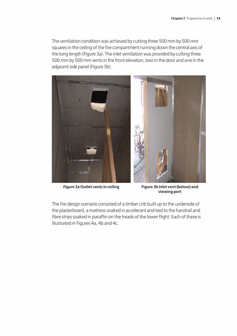
The ventilation condition was achieved by cutting three 500 mm by 500 mm squares in the ceiling of the fire compartment running down the central axis of the long length (Figure 3a). The inlet ventilation was provided by cutting three 500 mm by 500 mm vents in the front elevation, two in the door and one in the adjacent side panel (Figure 3b).
Figure 3a Outlet vents in ceiling Figure 3b Inlet vent (below) and viewing port
The fire design scenario consisted of a timber crib built up to the underside of the plasterboard, a mattress soaked in accelerant and tied to the handrail and fibre strips soaked in paraffin on the treads of the lower flight. Each of these is illustrated in Figures 4a, 4b and 4c.

14 | Fire Performance of Escape Stairs
Figure 4a Timber crib Figure 4b Double mattress
Figure 4c Porous fibre strips on lower flight
The mattress was placed in a steel tray containing approximately 1 litre of paraffin. On the timber crib, 0.5 litres of paraffin was used and a further 0.5 litres on the porous fibre strips. The crib was ignited first, followed immediately by the mattress and the fibre strips. Figures 5a, 5b and 5c show the process of ignition.

Chapter 2 Programme of work | 15
Figure 5a Pouring accelerant Figure 5b Ignition of mattress
Figure 5c Ignition of porous fibre strips
Once ignition had been completed and all operatives had exited the compartment, the door was shut and the test was observed through the viewing port and ventilation openings. Fire development was extremely rapid. The mattress quickly became fully involved (Figure 6) which accounted for the peak in atmosphere temperatures shown in Figure 7.

16 | Fire Performance of Escape Stairs
Figure 6 Full involvement of the mattress
0
100
200
300
400
500
600
700
800
900
0 50 100 150 200 250 300 350Time (s)
Tem
per
atu
re (
Deg
C)
t/c 1 t/c 2 t/c 3 t/c 4 t/c 5
Figure 7 Atmosphere temperatures – Test 1 (maximum temperature 784ºC)
The intensity of the mattress fire caused the string and spindles of the lower flight to ignite and the flames quickly reached the upper string. Once the string of the upper flight had become involved, the fixings to the plasterboard on the underside of the upper flight became dislodged and the plasterboard fell onto the floor allowing the flames to directly impinge on the underside of the treads and risers of the upper flight. At this point, the upper flight had become fully involved in the fire process and the test was terminated to prevent any unnecessary damage to the compartment. Figure 8 shows the upper flight involved in the fire development prior to the onset of fire fighting.

Chapter 2 Programme of work | 17
Figure 8 Fire spread showing direct flame impingement on underside of upper flight
The fire was quickly extinguished with minimal damage to the surrounding structure. There was evidence of deep charring to the strings on both the lower and upper flights (Figures 9a and 9b).
Figure 9a Charring to lower flight Figure 9b Charring to upper flight
The temperatures of the timber surface on both the upper and lower treads were measured along with the temperatures of the underside of each flight below the plasterboard. The results are illustrated in Figure 10.

18 | Fire Performance of Escape Stairs
0
100
200
300
400
500
600
700
0 50 100 150 200 250 300 350 400
Time (s)
Tem
per
atu
re (
Deg
C)
t/c 6 t/c 7 t/c 8 t/c 9 t/c 10 t/c 11 t/c 12 t/c 13
first water into compartment
Figure 10 Stair temperatures – Test 1
The peak at 180 seconds corresponds to the first water from fire-fighting operations going into the compartment. It is worth noting that this peak reading occurs later than the initial peak in the atmosphere temperature due to the rapid heat released by combustion of the mattress but does correspond to the second peak in the atmosphere temperatures indicating imminent flashover of the compartment.
The rapid fire spread and the involvement of the upper flight in the combustion process meant that the test sample failed the first part of the test dealing with reaction to fire issues. For this reason, the stability test, which involves loading the treads of the lower flight following the test, was not undertaken. The treads of the lower flight were in quite a good condition once the fire had been put out and were capable of supporting the weight of test operatives (Figure 11). The plasterboard on the underside of the lower flight stayed in place for the duration of the test and offered protection to the treads and risers. However, the only reasons why this flight remained usable were the speed of intervention and the efficiency of the suppression method. The test lasted for approximately three minutes.

Chapter 2 Programme of work | 19
Figure 11 Limited damage to treads of lower flight
2.3 Test 2 (sample 2)
The second test involved a straight flight unprotected stair. The purpose of this test configuration was to consider the difference between a dog-leg and a straight flight in terms of reaction to fire issues and residual load-bearing capacity. The test conditions were identical in terms of fire loading and ventilation conditions. However, based on experience in the previous test, two changes were made to the test procedure, as follows.
In the first test, the rapid ignition of the mattress raised health and safety issues relating to the final ignition of the porous fibre strips on the lower treads of the stair. For this reason, the ignition sequence was changed so that the timber crib under the stairs was ignited first, followed by the porous fibre strips on the treads and the mattress was ignited last. This procedure was adopted for the remaining tests.
During the first test, the mattress collapsed at a very early stage. This collapse is delayed if the mattress is tied back to the handrail/spindles by wire passing through the springs of the mattress. This procedure was adopted for the remaining tests.
As with the previous test, the initial fire development was very rapid. However, the configuration of the straight flight meant that fire spread to the upper strings was inhibited. Consequently, the test lasted much longer than the first test with an initial drop in temperature once the mattress had been consumed. The initial test configuration is shown in Figures 12a and 12b.

20 | Fire Performance of Escape Stairs
Figure 12a Straight flight stairs Figure 12b Timber crib
Figures 13a and 13b show the mattress at the early stages of the fire and once most of the material had become involved. The mattress retained its initial position much better when tied back through the springs.
Figure 13a Early stages of test Figure 13b Involvement of lower string and handrail
In the previous test, the flames impinged directly on the upper flight strings, resulting in the collapse of the plasterboard protecting the underside of the stair. In this case, the board stayed intact for a longer period. The test was finally terminated once flaming of the string had reached the landing level. At this point, the underside of the stairs had been subject to direct flaming for some

Chapter 2 Programme of work | 21
time, resulting in failure of a number of risers on the lower portion of the stairs. Consequently, there was no need to carry out the residual loading test.
Figures 14a and 14b show the spread of flame up the side of the stair and the break-out of flaming from beneath the lower treads and risers.
Figure 14a Breakthrough on lower treads Figure 14b Failure of treads and risers
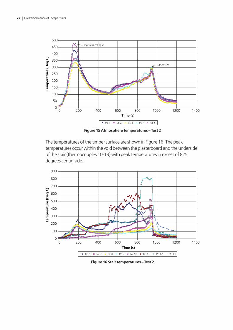
The atmosphere temperatures are shown in Figure 15 which shows clearly the effect of the mattress in the early stages and the gradual increase in temperature after approximately 8 minutes 40 seconds, indicating involvement of the staircase. The peak corresponding with the decision to terminate the test after nearly 16 minutes indicates a rapid increase in temperature corresponding to full involvement of the stair.
22 | Fire Performance of Escape Stairs
0
50
100
150
200
250
300
350
400
450
500
0 200 400 600 800 1000 1200 1400Time (s)
Tem
per
atu
re (
Deg
C)
t/c 1 t/c 2 t/c 3 t/c 4 t/c 5
mattress collapse
suppression
Figure 15 Atmosphere temperatures – Test 2
The temperatures of the timber surface are shown in Figure 16. The peak temperatures occur within the void between the plasterboard and the underside of the stair (thermocouples 10-13) with peak temperatures in excess of 825 degrees centigrade.
0
100
200
300
400
500
600
700
800
900
0 200 400 600 800 1000 1200 1400
Time (s)
Tem
per
atu
re (
Deg
C)
t/c 6 t/c 7 t/c 8 t/c 9 t/c 10 t/c 11 t/c 12 t/c 13
Figure 16 Stair temperatures – Test 2

Chapter 2 Programme of work | 23
2.4 Test 3 (sample 5)
The third test consisted of a dog-leg or scissors stair geometry identical to Test 1 except that the treads were constructed from medium density fibreboard (MDF) rather than whitewood.
Fire development was very similar to the first test. The test was terminated at an early stage owing to the involvement of the string to both the lower and upper flight. Figures 17a and 17b show the charring of these areas following the test.
Figure 17a Charring to lower flight Figure 17b Charring to upper flight
The test was terminated before any serious damage was done to the treads and risers. However, the stairs were clearly involved in the combustion process at an early stage with external flaming visible through the ventilation openings at the top of the compartment.
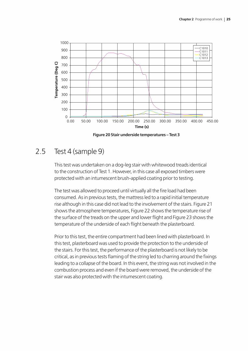
Figure 18 shows the atmosphere temperatures, Figure 19 shows the temperature of the timber surface on the upper and lower flights and Figure 20 shows the temperature of the void between the underside of the stair and the plasterboard fixed to the underside.
As the specimen did not achieve the required performance in the fire test, no attempt was made to apply a loading to the stair.

24 | Fire Performance of Escape Stairs
0
100
200
300
400
500
600
700
800
900
0.00 50.00 100.00 150.00 200.00 250.00 300.00 350.00 400.00 450.00 500.00
Time (s)
Tem
per
atu
re (
Deg
C)
C1001C1002C1003C1004C1005
Figure 18 Atmosphere temperatures – Test 3
0
50
100
150
200
250
300
350
400
450
0.00 50.00 100.00 150.00 200.00 250.00 300.00 350.00 400.00 450.00
Time (s)
Tem
per
atu
re (
Deg
C)
C1006C1007C1008C1009
Figure 19 Stair surface temperatures – Test 3
Chapter 2 Programme of work | 25
0
100
200
300
400
500
600
700
800
900
1000
0.00 50.00 100.00 150.00 200.00 250.00 300.00 350.00 400.00 450.00
Time (s)
Tem
per
atu
re (
Deg
C)
C1010C1011C1012C1013
Figure 20 Stair underside temperatures – Test 3
2.5 Test 4 (sample 9)
This test was undertaken on a dog-leg stair with whitewood treads identical to the construction of Test 1. However, in this case all exposed timbers were protected with an intumescent brush-applied coating prior to testing.
The test was allowed to proceed until virtually all the fire load had been consumed. As in previous tests, the mattress led to a rapid initial temperature rise although in this case did not lead to the involvement of the stairs. Figure 21 shows the atmosphere temperatures, Figure 22 shows the temperature rise of the surface of the treads on the upper and lower flight and Figure 23 shows the temperature of the underside of each flight beneath the plasterboard.
Prior to this test, the entire compartment had been lined with plasterboard. In this test, plasterboard was used to provide the protection to the underside of the stairs. For this test, the performance of the plasterboard is not likely to be critical, as in previous tests flaming of the string led to charring around the fixings leading to a collapse of the board. In this event, the string was not involved in the combustion process and even if the board were removed, the underside of the stair was also protected with the intumescent coating.

26 | Fire Performance of Escape Stairs
0
50
100
150
200
250
300
350
400
450
500
0.00 500.00 1000.00 1500.00 2000.00 2500.00 3000.00 3500.00 4000.00
Time (s)
Tem
per
atu
re (
Deg
C)
C1001C1002C1003C1004C1005
Figure 21 Atmosphere temperatures – Test 4
0
20
40
60
80
100
120
140
160
180
200
0.00 500.00 1000.00 1500.00 2000.00 2500.00 3000.00 3500.00 4000.00Time (s)
Tem
per
atu
re (D
eg C
)
C1006C1007C1008C1009
Figure 22 Stair surface temperatures – Test 4

Chapter 2 Programme of work | 27
0
50
100
150
200
250
300
0.00 500.00 1000.00 1500.00 2000.00 2500.00 3000.00 3500.00 4000.00
Time (s)
Tem
per
atu
re (
Deg
C)
C1010C1011C1012C1013
Figure 23 Stair underside temperatures – Test 4
On completion of the test, the few burning embers beneath the lower flight were extinguished (see Figure 24). The stair itself appeared to be in very good condition (see Figure 25). In many cases, what appeared to be charring of the timber was, in fact, activation of the intumescent coating and once the powdered char had been swept away, the undamaged surface of the timber was clearly visible (see Figure 26). This was the case even for slender members subjected to the full force of the mattress fire such as the handrail and spindles. Large circular patterns of intumescent char were formed on the strings of the stair (see Figure 27), insulating the solid material beneath.
Figure 24 Residual fire load Figure 25 Stair following test

28 | Fire Performance of Escape Stairs
Figure 26 Formation of char on top of handrail
Figure 27 Patterns of char formation on string of lower flight
In this case, the test specimen successfully achieved the performance requirement in relation to restricting fire spread and minimising the heat release rate. It was then necessary to assess load-bearing capacity. Once the compartment had cooled sufficiently, all unburnt material was removed and three displacement transducers were fixed to the centre of the second, third and fourth treads from the bottom of the lower flight (Figure 28).

Chapter 2 Programme of work | 29
Figure 28 Displacement transducers on underside of treads of lower flight
The upper treads were then loaded with 90 kg per tread over the middle three treads in the positions shown in Figure 29. This corresponds to a total load for the lower flight of 2.65 kN. Although some cracking was visible on the lower treads (Figure 30) prior to the application of the load, the stair carried the load without any significant deflection (Figure 31) and no localised or global collapse.
Figure 29 Load testing of lower flight

30 | Fire Performance of Escape Stairs
Figure 30 Cracking of lower tread perpendicular to direction of travel
-0.25
0
0.25
0.5
0.75
1
1.25
1.5
1.75
2
2.25
0 200 400 600 800 1000 1200 1400
Time (s)
Defl
ecti
on
(m
m)
∆C1021∆C1022∆C1023
Figure 31 Deflection of treads during load test – Test 4
The test specimen satisfied the performance criteria in relation to reaction to fire and residual fire resistance properties.

Chapter 2 Programme of work | 31
2.6 Test 5 (sample 13)
This test was identical to the previous test except that the treads were constructed from MDF. The original intention was for this sample to incorporate a floor covering. However, at this stage, a decision had not been taken on the appropriate material. The results are very similar to the previous case with the stair demonstrating adequate performance in relation to the criteria for reaction to fire and fire resistance. A good coating of the basecoat and topcoat was achieved using a brush application. The stair prior to ignition is shown in Figure 32.
Figure 32 Stair with brush-applied intumescent coating prior to ignition
Again, the test was allowed to continue until the fire load was virtually consumed. The results in relation to atmosphere temperature, specimen surface temperature, temperatures of the underside of each flight and deflection during the applied load test are shown in Figures 33 to 36. In this case, the load was applied incrementally using smaller weights owing to difficulties in applying the weights previously in a safe and efficient manner.

32 | Fire Performance of Escape Stairs
0
100
200
300
400
500
600
700
0.00 250.00 500.00 750.00 1000.00 1250.00 1500.00 1750.00 2000.00 2250.00 2500.00 2750.00 3000.00 3250.00 3500.00
Time (s)
Tem
per
atu
re (
Deg
C)
C1001C1002C1003C1004C1005
Figure 33 Atmosphere temperatures – Test 5
180
160
140
Tem
per
atu
re (
Deg
C)
Time (s)
120
100
80
60
40
20
00.00 250.00 500.00 750.00 1000.00 1250.00 1500.00 1750.00 2000.00 2250.00 2500.00 2750.00 3000.00 3250.00 3500.00
C1006C1007C1008C1009
Figure 34 Surface temperatures – Test 5

Chapter 2 Programme of work | 33
0
50
100
150
200
250
300
0.00 500.00 1000.00 1500.00 2000.00 2500.00 3000.00 3500.00
Time (s)
Tem
per
atu
re (
Deg
C)
C1010C1011C1012C1013
Figure 35 Stair underside temperatures – Test 5
0
0.5
1
1.5
2
2.5
0 100 200 300 400 500 600 700 800 900 1000
Time (s)
Defl
ecti
on
(m
m)
∆C1021∆C1022∆C1023
Figure 36 Deflection of treads during load test – Test 5
Again, the test specimen met the performance requirements of the test. The coating provided an intumescent barrier to protect the timber beneath.

34 | Fire Performance of Escape Stairs
2.7 Test 6 (sample 3)
This test was the first sample to incorporate an impregnation treatment to provide a notional Class 1 performance. Because of problems with the procurement of test samples and difficulties in curing the test specimens during the treatment process, there was a significant delay in undertaking these tests. For this test and the subsequent two tests, no detailed measurements are available owing to a failure of the data acquisition system. However, the tests were completed successfully and observations and video footage were taken.
The test sample survived both the fire test and the subsequent post-fire load test. Observations taken during the test indicate that peak temperatures and post-test behaviour were very similar to those in Test 4 which was protected using a surface treatment. However, in this case two of the risers located immediately above the timber crib had burnt through by the end of the fire test (Figure 37). The plasterboard fixed to the underside of the stair fell off 10 minutes into the test and the underside of the stair was then exposed directly to the fire. Figure 38 shows the stair during the post-fire load test.
Figure 37 Latter stages of the fire test showing burn-through of risers and localised
flaming of stairs

Chapter 2 Programme of work | 35
Figure 38 Post-fire load test
2.8 Test 7 (sample 11)
This test on a sample treated with an impregnation process was the first to incorporate a stair covering. After a search of the available literature and discussion with suppliers, it was concluded that two types of carpet are usually used to provide the covering to stairs – polypropylene and wool fitted over a rubber underlay. The wool carpet was used for this test.
The carpet made little difference to the overall performance in terms of fire spread or heat release. Atmosphere temperatures were similar to previous tests on treated specimens, with a peak value of approximately 700 degrees centigrade during the early stages and the major contribution coming from the mattress. The carpet ignited very early on the treads incorporating the paraffin soaked strips. However, fire spread was limited to the lower flight even though the carpet was continuous across the half landing and onto the upper flight. Relative to the previous test, the carpet provided some protection to the upper surface of the stair. In this case, there was no burn through of the risers although the plasterboard sheet to the underside of the stairs remained intact for the duration of the test. Figure 39 shows the carpet burning on the surface during the early stages of the fire test. Figure 40 shows the residual debris on the surface of the stair following completion of the test.
The residual load test was successfully completed.

36 | Fire Performance of Escape Stairs
Figure 39 Surface burning of the carpet on the treads
Figure 40 Remains of the carpet on the lower flight

Chapter 2 Programme of work | 37
2.9 Test 8 (sample 8)
This test involved a straight flight treated with an impregnation process to a notional Class 1 standard. A section of plasterboard sheet fixed to the underside of the stairs fell down 10 minutes into the test allowing the flames from the crib to directly impact on the underside of the stair. This caused significant damage to the risers and some localised flaming of the treads. The damage to the risers and the localised flaming of the timber is illustrated in Figure 41.
Figure 41 Burn-through and localised flaming of riser and junction between tread
and riser
The post-fire load test was completed successfully. However, on removal of the load after 30 minutes, it was noted that the treads were badly damaged and would not have continued to perform a load-bearing function for long after this period. The problem was in part due to cracking along the joints where individual timber sections had been joined to make the tread. These cracks were apparent on a number of the specimens subjected to the impregnation treatment.

38 | Fire Performance of Escape Stairs
2.10 Test 9 (sample 14)
This test involved a return flight (dog-leg) stair treated with an impregnation process to achieve a notional Class 1 standard. The test incorporated a wool-based carpet covering the lower flight, half landing and upper flight. The treads and risers were MDF pre-treated to give the required reaction to fire performance. The stairs were underdrawn with a single layer of plasterboard fixed with nails to the string. The carpet did not cover the entire surface of the treads but was located centrally on both flights with underlay across the entire width, as shown in Figure 42.
Figure 42 Lower flight of stairs prior to ignition showing location of woollen carpet
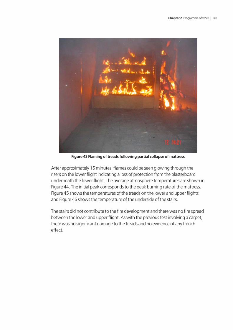
As with previous tests, fire development was very rapid with flames reaching the top of the compartment and impacting on the upper flight. However, once the initial impact from the mattress had died down there was no sign of fire spread away from the initial seats of ignition (Figure 43).
Chapter 2 Programme of work | 39
Figure 43 Flaming of treads following partial collapse of mattress
After approximately 15 minutes, flames could be seen glowing through the risers on the lower flight indicating a loss of protection from the plasterboard underneath the lower flight. The average atmosphere temperatures are shown in Figure 44. The initial peak corresponds to the peak burning rate of the mattress. Figure 45 shows the temperatures of the treads on the lower and upper flights and Figure 46 shows the temperature of the underside of the stairs.
The stairs did not contribute to the fire development and there was no fire spread between the lower and upper flight. As with the previous test involving a carpet, there was no significant damage to the treads and no evidence of any trench effect.

40 | Fire Performance of Escape Stairs
0
50
100
150
200
250
300
350
400
450
500
0 200 400 600 800 1000 1200 1400 1600 1800
Time (s)
Tem
per
atu
re (
Deg
C)
Figure 44 Average atmosphere temperatures – Test 9
-100
0
100
200
300
400
500
600
0 200 400 600 800 1000 1200 1400 1600 1800
Time (s)
Tem
per
atu
re (
Deg
C)
lower flight 1 lower flight 2 upper flight 1 upper flight 2
Figure 45 Stair surface temperatures – Test 9

Chapter 2 Programme of work | 41
-20
0
20
40
60
80
100
120
140
0 200 400 600 800 1000 1200 1400 1600 1800
Time (s)
Tem
per
atu
re (
Deg
C)
under stair lower flight 1 under stair lower flight 2 under stair upper flight 1 understair upper flight 2
Figure 46 Stair underside temperatures – Test 9
The extent of fire spread can be seen in Figure 47 which shows the stair at the end of the test with the carpet on the lowest and highest treads of the lower flight still intact.
Figure 47 Post-test condition of the lower flight – Test 9
Following the successful completion of the fire test, the central three treads of the lower flight were loaded in the same manner as described previously and the displacement of the treads monitored for a period of 30 minutes. The deflection of the treads during the load test is shown in Figure 48. The stair maintained the applied load for the required time period with no localised collapse.

42 | Fire Performance of Escape Stairs
-0.5
0
0.5
1
1.5
2
2.5
3
0 500 1000 1500 2000 2500
Time (s)
Defl
ecti
on
(m
m)
tread 1 tread 2 tread 3
Figure 48 Deflection of treads during load test – Test 9
2.11 Test 10 (sample 6)
This test involved a straight flight stair treated with an impregnation process to a notional Class 1 standard. The treads and risers were MDF pre-treated to give the required reaction to fire performance. The stairs were underdrawn with a single layer of plasterboard fixed with nails to the string.
Figure 49 Fully developed fire – Test 10

Chapter 2 Programme of work | 43
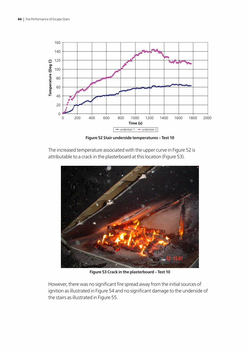
Figure 50 shows the average atmosphere temperatures. Figures 51 and 52 show the corresponding temperatures on the surface of the treads and the underside of the stair.
0
50
100
150
200
250
300
350
400
450
0 200 400 600 800 1000 1200 1400 1600 1800 2000
Time (s)
Tem
per
atu
re (
Deg
C)
Figure 50 Average atmosphere temperatures – Test 10
0
50
100
150
200
250
300
350
0 200 400 600 800 1000 1200 1400 1600 1800 2000Time (s)
Tem
per
atu
re (
Deg
C)
2nd tread 5th tread
Figure 51 Stair surface temperatures – Test 10
44 | Fire Performance of Escape Stairs
0
20
40
60
80
100
120
140
160
0 200 400 600 800 1000 1200 1400 1600 1800 2000Time (s)
Tem
per
atu
re (
Deg
C)
understair 1 understair 2
Figure 52 Stair underside temperatures – Test 10
The increased temperature associated with the upper curve in Figure 52 is attributable to a crack in the plasterboard at this location (Figure 53).
Figure 53 Crack in the plasterboard – Test 10
However, there was no significant fire spread away from the initial sources of ignition as illustrated in Figure 54 and no significant damage to the underside of the stairs as illustrated in Figure 55.

Chapter 2 Programme of work | 45
Figure 54 Limited fire damage following Test 10
Figure 55 Limited damage to underside of stair – Test 10
Following the successful completion of the fire test, the stair was loaded in accordance with the draft procedure and the deflection monitored. There was no collapse of the stair either during or following the loading test. The deflection of treads during the load test is shown in Figure 56.

46 | Fire Performance of Escape Stairs
-0.5
0
0.5
1
1.5
2
2.5
3
0 200 400 600 800 1000 1200 1400 1600 1800 2000
Time (s)
Defl
ecti
on
(m
m)
tread 1 tread 2 tread 3
Figure 56 Deflection of treads during load test – Test 10
2.12 Test 11 (sample 7)
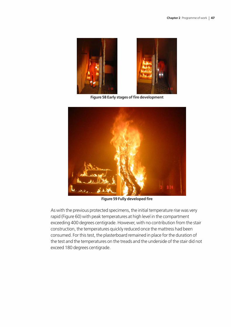
This was the first test sample protected with an impregnation treatment to achieve a Class 0 performance in relation to reaction to fire performance and consisted of a dog-leg stair with treated MDF treads. The lower flight just prior to ignition is shown in Figure 57. The progress of fire development is illustrated in Figures 58 and 59.
Figure 57 Lower flight prior to ignition
Chapter 2 Programme of work | 47
Figure 58 Early stages of fire development
Figure 59 Fully developed fire
As with the previous protected specimens, the initial temperature rise was very rapid (Figure 60) with peak temperatures at high level in the compartment exceeding 400 degrees centigrade. However, with no contribution from the stair construction, the temperatures quickly reduced once the mattress had been consumed. For this test, the plasterboard remained in place for the duration of the test and the temperatures on the treads and the underside of the stair did not exceed 180 degrees centigrade.

48 | Fire Performance of Escape Stairs
0
50
100
150
200
250
300
350
400
450
0.00 5.00 10.00 15.00 20.00 25.00 30.00 35.00
Time (min)
Tem
per
atu
re (
Deg
C)
C1001C1002C1003C1004C1005
Figure 60 Atmosphere temperatures – Test 11
There was only limited charring to the handrail, string and spindles adjacent to the mattress area and a brief removal of the surface char revealed the solid timber beneath (Figure 61). Away from the direct contact with the mattress there was no significant evidence of charring.
Figure 61 Localised charring and condition of timber following Test 11
As the specimen attained the required performance in relation to reaction to fire, the stair was loaded in the manner described previously and readings taken of the deflection of the second, third and fourth treads of the lower flight (Figure 62). The stair continued to maintain the load for the required duration and the loads were removed and the stair dismantled ready for installation of the next specimen.

Chapter 2 Programme of work | 49
-0.5
0
0.5
1
1.5
2
2.5
3
3.5
4
4.5
0.00 5.00 10.00 15.00 20.00 25.00 30.00 35.00
Time (min)
Defl
ecti
on
(m
m)
C1021C1022C1023
Figure 62 Deflection of treads during load test – Test 11
2.13 Test 12 (sample 12)
This specimen was made up from MDF treads supplied as Class 0 in relation to reaction to fire properties and included a stair covering. In this case, the specimen consisted of a rubber underlay covered with a polypropylene carpet. Carpet was included on both the upper and lower flights and the landing (Figure 63).
Figure 63 Test specimen showing carpet on lower flight and landing
Prior to carrying out the test, a small sample of the polypropylene carpet was set alight. The carpet, once ignited, smouldered for a long period giving off large quantities of black smoke with an unpleasant odour. The test was undertaken with the laboratory door open to reduce the risk of breathing the products of combustion. This made no significant difference to the test. The atmosphere temperatures are shown in Figure 64 and are very similar to previous results where the stair has made no significant contribution to fire development.

50 | Fire Performance of Escape Stairs
500
Tem
per
atu
re (
Deg
C)
Time (min)
450
400
350
300
250
200
150
100
50
00.00 5.00 10.00 15.00 20.00 25.00 30.00 35.00
C1001C1002C1003C1004C1005
Figure 64 Atmosphere temperatures – Test 12
The presence of the carpet increased the temperatures measured on the treads of the lower flight (Figure 65) but did not provide a route for fire spread up to the landing and the upper flight and did not result in any significant damage to the MDF treads or the timber.
0
100
200
300
400
500
600
700
800
0.00 5.00 10.00 15.00 20.00 25.00 30.00 35.00
Time (min)
Tem
per
atu
re (
Deg
C)
C1006C1007C1008C1009
Figure 65 Stair surface temperatures – Test 12
Charring of the string and spindles was similar to previous tests and damage to the lower flight was restricted to cracking of the risers (Figure 66).

Chapter 2 Programme of work | 51
Figure 66 Post-fire test damage
As previously, the most seriously affected treads of the lower flight were loaded and the load maintained for 30 minutes while recording deflection (Figure 67).
-0.5
0
0.5
1
1.5
2
0.00 5.00 10.00 15.00 20.00 25.00 30.00 35.00 40.00 45.00
Time (min)
Defl
ecti
on
(m
m)
C1021C1022C1023
Figure 67 Deflection of treads during load test – Test 12
2.14 Test 13 (sample 4)
The final test specimen consisted of whitewood treads protected using an impregnation treatment to achieve a Class 0 performance in relation to reaction to fire properties. No floor covering was used. The stair prior to testing is shown in Figure 68.

52 | Fire Performance of Escape Stairs
Figure 68 Lower flight prior to ignition
The fire development was very similar to previous tests with peak temperatures in excess of 450 degrees centigrade at high level for very short duration (Figure 69). Unlike the previous test incorporating a combustible floor covering, surface temperatures did not exceed 150 degrees centigrade and reduced quite rapidly in line with the reduction in atmosphere temperature.
0
50
100
150
200
250
300
350
400
450
500
0.00 5.00 10.00 15.00 20.00 25.00 30.00 35.00
Time (min)
Tem
per
atu
re (
Deg
C)
C1001C1002C1003C1004C1005
Figure 69 Atmosphere temperatures – Test 13
There was limited and superficial damage to the specimen following the fire test (Figure 70) and the lower flight was loaded in the prescribed manner. The stair supported the applied load for the duration of the test with no significant damage. Deflection readings are shown in Figure 71.

Chapter 2 Programme of work | 53
Figure 70 Limited damage to string and newell post – Test 13
-0.4
-0.2
0
0.2
0.4
0.6
0.8
1
1.2
1.4
1.6
1.8
0.00 5.00 10.00 15.00 20.00 25.00 30.00 35.00 40.00 45.00
Time (min)
Defl
ecti
on
(m
m)
C1021C1022C1023
Figure 71 Deflection of treads during load test – Test 13
2.15 Comparison of results
Table 2 shows a summary of the test parameters and significant observations from the experimental programme.
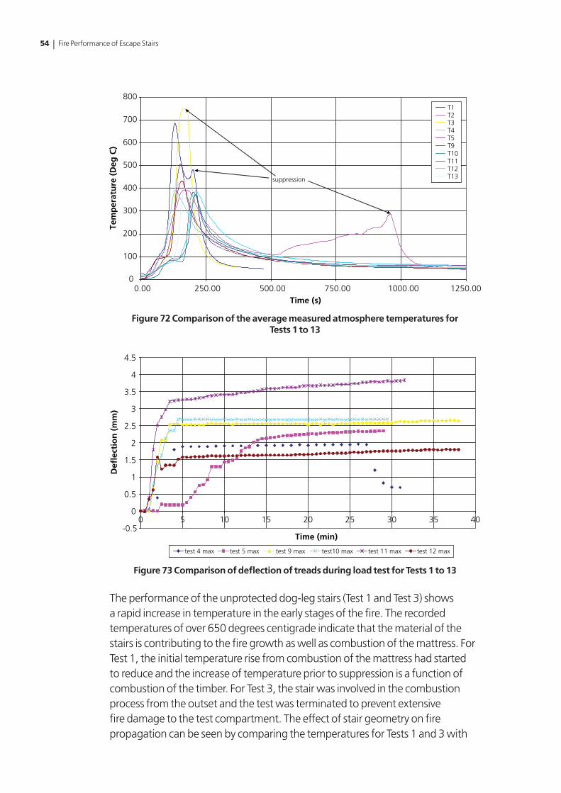
Figure 72 shows a comparison of the average measured atmosphere temperatures for Tests 1 to 13. Figure 73 shows a comparison of the deflection readings for Tests 1 to 13.
54 | Fire Performance of Escape Stairs
0
100
200
300
400
500
600
700
800
0.00 250.00 500.00 750.00 1000.00 1250.00Time (s)
Tem
per
atu
re (
Deg
C)
suppression
T1T2T3T4T5T9T10T11T12T13
Figure 72 Comparison of the average measured atmosphere temperatures for Tests 1 to 13
-0.5
0
0.5
1
1.5
2
2.5
3
3.5
4
4.5
0 5 10 15 20 25 30 35 40
Time (min)
Defl
ecti
on
(m
m)
test 4 max test 5 max test 9 max test10 max test 11 max test 12 max
Figure 73 Comparison of deflection of treads during load test for Tests 1 to 13
The performance of the unprotected dog-leg stairs (Test 1 and Test 3) shows a rapid increase in temperature in the early stages of the fire. The recorded temperatures of over 650 degrees centigrade indicate that the material of the stairs is contributing to the fire growth as well as combustion of the mattress. For Test 1, the initial temperature rise from combustion of the mattress had started to reduce and the increase of temperature prior to suppression is a function of combustion of the timber. For Test 3, the stair was involved in the combustion process from the outset and the test was terminated to prevent extensive fire damage to the test compartment. The effect of stair geometry on fire propagation can be seen by comparing the temperatures for Tests 1 and 3 with

Chapter 2 Programme of work | 55
Test 2 where a straight flight was subject to the same fire load. The temperatures are much lower and there was no significant involvement of the stair during the early stages of the test. The temperature rise at approximately 23 minutes on the horizontal axis is a result of combustion of the stair from the timber crib located on the underside of the stair.
The specimens protected with a surface intumescent treatment (Tests 4 and 5) performed extremely well with only limited charring of the string and spindles despite the proximity of the mattress to these elements.
The tests utilising the impregnation treatment to achieve a notional Class 1 performance satisfied the criteria in relation to reaction to fire and post-fire stability. However, the damage from the fire was more significant in this case, with significant damage to the risers and localised flaming of the treads observed in Test 8.
The influence of the floor covering was insignificant in relation to the overall fire load. Fire spreads quickly over the surface in the early stages but does not adversely affect the performance of the stairs. The surface covering, whether wool or polypropylene carpet, did not provide a route for fire spread up the stairs and for the dog-leg specimens there was no fire spread to either the landing or the upper flight.
The specimens protected with an impregnation treatment to achieve a notional Class 0 performance satisfied the criteria for the test in relation to fire spread and load-bearing capacity, and did not exhibit any significant damage following the test.

56 | Fire Performance of Escape Stairs
Tab
le 2
Sum
mar
y of
test
resu
lts
Test
n
o.
Sam
ple
n
o.
Stai
r g
eom
etry
Tim
ber
typ
e/sp
ecie
s Tr
ead
s an
d R
iser
s
Trea
tmen
t pro
cess
Stai
r co
veri
ng
Res
ult
s R
eact
ion
to
fire
test
Res
ult
s Po
st-fi
re
load
test
Co
mm
ents
11
Dog
-leg
Whi
tew
ood
Unp
rote
cted
Non
eFa
iled
Not
ap
plic
able
Test
term
inat
ed a
fter
3 m
inut
es
22
Stra
ight
fli
ght
Whi
tew
ood
Unp
rote
cted
Non
eFa
iled
Not
ap
plic
able
Test
term
inat
ed a
fter
16
min
utes
35
Dog
-leg
MD
FU
npro
tect
edN
one
Faile
dN
ot
appl
icab
leTe
st te
rmin
ated
aft
er 3
min
utes
49
Dog
-leg
Whi
tew
ood
Surf
ace
trea
tmen
t (in
tum
esce
nt)
Non
ePa
ssed
Pass
edN
o si
gnifi
cant
dam
age
obse
rved
513
Dog
-leg
MD
FSu
rfac
e tr
eatm
ent
(intu
mes
cent
)N
one
Pass
edPa
ssed
No
sign
ifica
nt d
amag
e ob
serv
ed
63
Dog
-leg
Whi
tew
ood
Pres
sure
impr
egna
tion
(Cla
ss 1
)N
one
Pass
edPa
ssed
Rise
rs b
urnt
thro
ugh
711
Dog
-leg
Whi
tew
ood
Pres
sure
impr
egna
tion
(Cla
ss 1
)W
ool c
arpe
t w
ith ru
bber
un
derla
y
Pass
edPa
ssed
No
sign
ifica
nt d
amag
e ob
serv
ed
88
Stra
ight
fli
ght
Whi
tew
ood
Pres
sure
impr
egna
tion
(Cla
ss 1
)N
one
Pass
edPa
ssed
Rise
rs b
urnt
thro
ugh,
stai
r un
safe
for u
se a
fter
com
plet
ion
of lo
ad te
st
914
Dog
-leg
MD
FPr
essu
re im
preg
natio
n (C
lass
1)
Woo
l car
pet
with
rubb
er
unde
rlay
Pass
edPa
ssed
No
sign
ifica
nt d
amag
e
106
Stra
ight
fli
ght
MD
FPr
essu
re im
preg
natio
n (C
lass
1)
Non
ePa
ssed
Pass
edN
o si
gnifi
cant
dam
age

Chapter 2 Programme of work | 57
Tab
le 2
Sum
mar
y of
test
resu
lts
Test
n
o.
Sam
ple
n
o.
Stai
r g
eom
etry
Tim
ber
typ
e/sp
ecie
s Tr
ead
s an
d R
iser
s
Trea
tmen
t pro
cess
Stai
r co
veri
ng
Res
ult
s R
eact
ion
to
fire
test
Res
ult
s Po
st-fi
re
load
test
Co
mm
ents
117
Dog
-leg
MD
FPr
essu
re im
preg
natio
n (C
lass
0)
Non
ePa
ssed
Pass
edN
o si
gnifi
cant
dam
age
1212
Dog
-leg
MD
FPr
essu
re im
preg
natio
n (C
lass
0)
Poly
prop
ylen
e ca
rpet
with
ru
bber
un
derla
y
Pass
edPa
ssed
No
sign
ifica
nt d
amag
e
134
Dog
-leg
Whi
tew
ood
Pres
sure
impr
egna
tion
(Cla
ss 0
)N
one
Pass
edPa
ssed
No
sign
ifica
nt d
amag
e

58 | Fire Performance of Escape Stairs
Chapter 3
Conclusions
The conclusions are as follows:
• Unprotectedtimberstairsareincapableofsurvivingthefirescenariousedinthe draft test procedure.
• Thereturnflightwithintermediatelanding(dog-leg)stairgeometryprovidesa worst case in relation to fire spread.
• Thestraightflightgeometryprovidesaworstcaseintermsofstructuralstability.
• Thespecimensprotectedwithanintumescentsurface-appliedtreatmentsurvived both the fire test and the post-fire structural stability test without any significant damage. There was no significant difference between the performance of the whitewood and medium density fibreboard (MDF) treads.
• Thespecimensprotectedwithapressureimpregnationtreatmenttoachievea notional Class 1 performance survived both the fire test and the post-fire structural stability test. For the straight flight specimen (Test 8) the stair was not safe to use once the load had been removed.
• Thespecimensprotectedwithapressureimpregnationtreatmenttoachievea notional Class 0 performance survived both the fire test and the post-fire structural stability test without any significant damage.
• Theinclusionofsurfacecoveringsdidnothaveadetrimentaleffectontheperformance of the stair and did not provide a route for fire spread up the stair or between the stair and landing.

References | 59
References
1. Lennon T, Bullock M J and Enjilly V, The fire resistance of medium-rise timber frame buildings, Proceedings of the World Conference on Timber Engineering, Whistler, Canada, 2000.

ISBN 978-1409816539
9 781409 816539
ISBN: 978 1 4098 1653 9Price: £11.00