fire protection in electrical technology – a guide to fireproof … · · 2018-03-154 obo 05...
TRANSCRIPT
Fire protection in electrical technology –a guide to fireproofbuilding installations

2 OBO
05 B
SS
_Bra
ndsc
hutz
info
rmat
ion_
Eur
opa
| OB
O |
/ en
/ 06/
03/2
012
(LLE
xpor
t_01
392)
About this guide
Protecting lives. Protecting goods.
Nowadays, fire protection presents many planners and installation engi-neers of building equipment with almost insurmountable obstacles. Instal-lations run like networks through complex building structures. The art ofthe planner is to harmonise the various networks, such as supply anddisposal, heating, ventilation and air-conditioning, with the electrical in-stallation. That in itself is difficult. In addition, the thought of building safe-ty has now been at the forefront for several years now. The sensitivity to-wards fire protection in buildings is growing.
As soon as the first step towards fire protection planning has been com-pleted, the appropriate systems and components are installed. Here, too,installation engineers are confronted with requirements which cannot beimplemented without further work.
After erection, the fire protection building equipment must be ready foracceptance. All the installations must be executed properly and the ap-propriate fire protection proofs must be available.
In this small brochure, we wish to explain the interconnections of fire pro-tection in technical building equipment. Perhaps you will find some newaspects which can help you in the planning or implementation of fire pro-tection systems.
Stefan RingDipl.-Ing. (FH), Electrical EngineeringTechnical planner for building fire protection (EIPOS)Product Manager, Fire Protection Systems

3OBO
05 B
SS
_Bra
ndsc
hutz
info
rmat
ion_
Eur
opa
| OB
O |
/ en
/ 06/
03/2
012
(LLE
xpor
t_01
392)
Table of contents
1. General introduction 4
2. Maintenance of the fire sections – Protection aim 1 24
3. Protection of escape routes – Protection aim 2 40
4. Function maintenance for electrical systems – Protection aim 3 56
5. Additional protection aims 88
6. Fire protection from OBO Bettermann 96
7. Imprint 114

4 OBO
05 B
SS
_Bra
ndsc
hutz
info
rmat
ion_
Eur
opa
| OB
O |
/ en
/ 06/
03/2
012
(LLE
xpor
t_01
392)
Chapter 1General introduction
Fire
Fire is a caring power,how it cares for people, guards themand that which they createthanks to this heavenly force.But this force will become fearsomewhen it bursts its bonds –it will take its own course,this free daughter of nature.
Friedrich Schiller, 1799

5OBO
05 B
SS
_Bra
ndsc
hutz
info
rmat
ion_
Eur
opa
| OB
O |
/ en
/ 06/
03/2
012
(LLE
xpor
t_01
392)
Chapter 1 | General introduction
1.1 Construction law 6
1.2 What is fire protection? 10
1.3 Fire protection concepts 12
1.4 Building types 14
1.5 What happens during a fire? 16
1.6 Construction law protection aims 22
6 OBO
05 B
SS
_Bra
ndsc
hutz
info
rmat
ion_
Eur
opa
| OB
O |
/ en
/ 06/
03/2
012
(LLE
xpor
t_01
392)
Chapter 1 | General introduction
1.1 Construction law
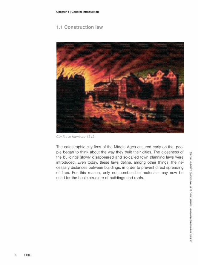
City fire in Hamburg 1842
The catastrophic city fires of the Middle Ages ensured early on that peo-ple began to think about the way they built their cities. The closeness ofthe buildings slowly disappeared and so-called town planning laws wereintroduced. Even today, these laws define, among other things, the ne-cessary distances between buildings, in order to prevent direct spreadingof fires. For this reason, only non-combustible materials may now beused for the basic structure of buildings and roofs.

7OBO
05 B
SS
_Bra
ndsc
hutz
info
rmat
ion_
Eur
opa
| OB
O |
/ en
/ 06/
03/2
012
(LLE
xpor
t_01
392)
Chapter 1 | General introduction
Building regulationsIn Germany, the model building regulations serve as a basis for the erec-tion of structures and the use of construction products. As constructionlaw is the business of the federal states, in German states this basis wasintroduced as state construction regulations in the appropriate law. Thereare currently no standard European regulations. National regulationsshould be complied with. However, one thing is certain: fires in Spain arethe same as fires in Germany.
General requirementsConstruction requirements place basic requirements on construction sy-stems. According to them, a construction project is to be "arranged,erected, modified and maintained in such a way that public safety and or-der, and in particular life, health and natural requirements for life, are notendangered."[1] This means people and property and their surroundings.Depending on the area concerned, the responsibilities lay with the plan-ner, craftsman or operator.
Fire protection in the construction regulationsThe first fire protection requirements are, for example, defined in §14 ofthe German MBR. The building must have been erected as already des-cribed in the general requirements, in order to "prevent the creation of fi-res and the spread of fire and smoke, and allow the rescue of peopleand animals as well as effective extinguishing measures."[2] This setsthree important protection aims.

8 OBO
05 B
SS
_Bra
ndsc
hutz
info
rmat
ion_
Eur
opa
| OB
O |
/ en
/ 06/
03/2
012
(LLE
xpor
t_01
392)
Chapter 1 | General introduction
Guidelines for electrical installationsBesides the basic national requirements from construction law, there arealso requirements from the field of electrical engineering. These are spe-cified by, for example, VDE, ÖVE, KEMA-KEUR and other institutions. Ho-wever, with regard to fire protection, only the technical systems are des-cribed here. Additional construction regulations specify which constructi-on measures must be applied. In Germany, the master cable installationguideline (MLAR) [3] was introduced as a technical construction regulati-on to the applicable construction law of the German federal states. Thisdirective specifies the fire protections requirements for installations inbuildings. It applies to electrical, sanitary and heating cable systems, butnot to ventilation systems. The MLAR applies to installations in emergen-cy routes, cable routing through walls completing a room and ceilings,as well as to systems with electrical function maintenance in case of fire.Thus, the protection aims according to the construction regulations areimplemented in practice. There are similar regulations or directives inother European countries, which are dedicated to the topic of fire protec-tion in buildings.

9OBO
05 B
SS
_Bra
ndsc
hutz
info
rmat
ion_
Eur
opa
| OB
O |
/ en
/ 06/
03/2
012
(LLE
xpor
t_01
392)
Chapter 1 | General introduction

10 OBO
05 B
SS
_Bra
ndsc
hutz
info
rmat
ion_
Eur
opa
| OB
O |
/ en
/ 06/
03/2
012
(LLE
xpor
t_01
392)
Chapter 1 | General introduction
1.2 What is fire protection?
General fire protection consists of four main pillars: the construction, sy-stems and organisational fire protection and combative fire protection.This division means that the different areas and their aims can be defi-ned more accurately.
Construction fire protectionDepending on the type of use of buildings, the building regulations andspecial building regulations of the German federal states place differentrequirements on construction protection. On the construction side, firesections are formed, fire-resistant components defined or the positionand length of escape routes specified.
Four pillars for compre-hensive fire protection

11OBO
05 B
SS
_Bra
ndsc
hutz
info
rmat
ion_
Eur
opa
| OB
O |
/ en
/ 06/
03/2
012
(LLE
xpor
t_01
392)
Chapter 1 | General introduction
System fire protectionThe use of special systems minimises fire risks, protects emergency andescape routes and maintains functions. These systems, e.g. sprinkler, firealarm or safety lighting systems, are either required by construction lawor are installed for private interests.
Preventive and combati-ve fire protection
Company organised fire protectionThis area includes the known escape route plans, fire protection ordi-nances or behaviour instructions for people in case of fire. This is to en-sure that controlled procedures are carried out should an emergency oc-cur, in order to minimise the risks to personnel and visitors, who oftenknow little about the building. The creation of a company or plant fire bri-gade is also a part of the organisational measures. The tasks are ofcourse part of combative fire protection.
Combative fire protectionThe creation, organisation and maintenance of a fire brigade is part ofthe field of preventive fire protection. All the vehicles and devices, and al-so the functions and deployment tactics of the personnel employed, arespecified. The tasks of the fire brigade are primarily fire-fighting and tech-nical assistance. Fire brigades can be both public and private. Each townis obliged to maintain a fire brigade. In business, plant or company firebrigades may exist and usually carry out preventive fire protection withincompanies.
All four areas must achieve the set protection aims within a specific fra-mework. This can be done in various ways. However, 100% safety can-not be achieved, not least because all the fire protection measures mustalso be economically viable.

12 OBO
05 B
SS
_Bra
ndsc
hutz
info
rmat
ion_
Eur
opa
| OB
O |
/ en
/ 06/
03/2
012
(LLE
xpor
t_01
392)
Chapter 1 | General introduction
1.3 Fire protection concepts
When planning a building project, one must ask oneself the question ofwhich protection aims are actually required. Is personal protection thekey aim, e.g. in meeting places, or is it protection of property? The possi-ble risks and dangers must be weighed up.
Observe fire protection,even during the plan-ning phase
Economic aspectsIt wise to combine the maximum of risk reduction with the minimum of fi-nancial cost. A production facility in the chemical industry, must be pro-tected against failure for the sake of the operator, though there is no pu-blic interest. However, the insurance companies may require special fireprotection measures.
Planning basicsThe fire protection concept is used to view a building in its entirety and torecord all the risks and dangers. The fire protection concept specifies theprotection aims for the building and special and general fire protectionmeasurements, and implementation of the same for the operation of thebuilding. The most important basic principle is that safe, risk-free operati-on must be possible.

13OBO
05 B
SS
_Bra
ndsc
hutz
info
rmat
ion_
Eur
opa
| OB
O |
/ en
/ 06/
03/2
012
(LLE
xpor
t_01
392)
Chapter 1 | General introduction
Overall view
Application-specific fire risks• Fire risks• Fire impact
Protection aims• General protection aims• Special protection aims
General and special fire protection measures
Fire protection concept
Specified protection aims must be achieved.
Creation and operation must be economic.

14 OBO
05 B
SS
_Bra
ndsc
hutz
info
rmat
ion_
Eur
opa
| OB
O |
/ en
/ 06/
03/2
012
(LLE
xpor
t_01
392)
Chapter 1 | General introduction
1.4 Building types
Not every building is subject to the high fire protection requirements. The-refore, in Germany the MBO makes a distinction between various buil-ding classes, which each have different fire protection requirements.Clas-ses 1 to 3 mostly contain smaller buildings, in which usually few peopleare to be found. Higher buildings below the tower block limit of 22 me-tres are to be found in classes 4 & 5.
Increasing requirementsdepending on buildingtype and use
Special constructionsRequirements increase as construction systems get larger.Special struc-tures such as industrial buildings, tower blocks or meeting places aresubjected to particularly high requirements, regulated by special specifi-cations. It is possible that a building complex may be divided into varioussections, the fire protection of which is viewed and evaluated in differentways according to the type of use. If there are no special regulations fora building, the minimum requirements of the appropriate state buildingregulations apply.
Different objectives: Protecting people or property
15OBO
05 B
SS
_Bra
ndsc
hutz
info
rmat
ion_
Eur
opa
| OB
O |
/ en
/ 06/
03/2
012
(LLE
xpor
t_01
392)
Chapter 1 | General introduction
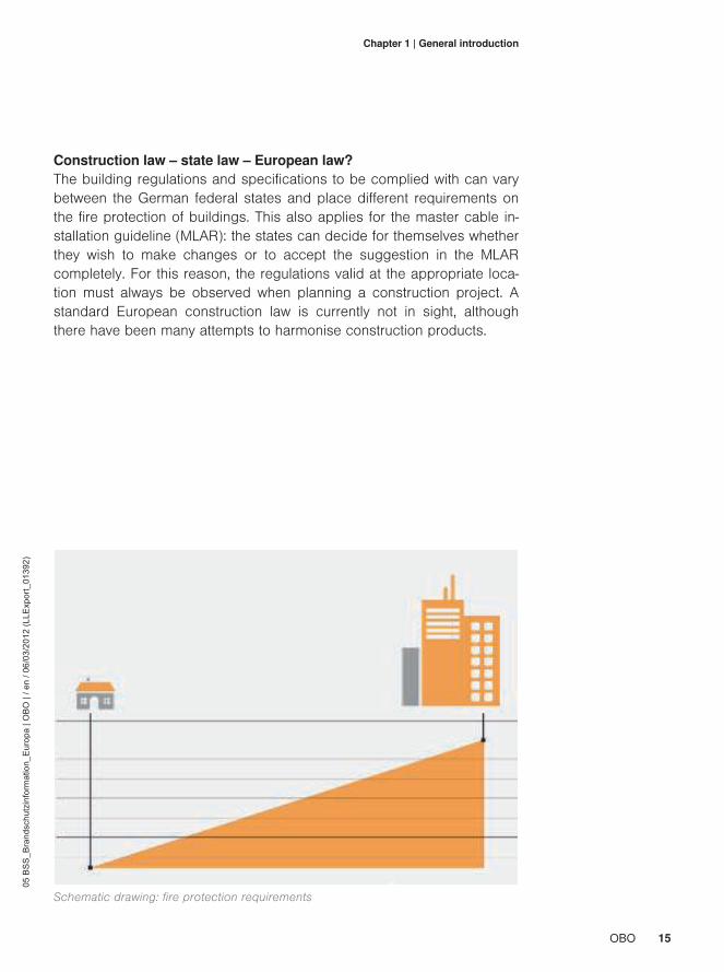
Construction law – state law – European law?The building regulations and specifications to be complied with can varybetween the German federal states and place different requirements onthe fire protection of buildings. This also applies for the master cable in-stallation guideline (MLAR): the states can decide for themselves whetherthey wish to make changes or to accept the suggestion in the MLARcompletely. For this reason, the regulations valid at the appropriate loca-tion must always be observed when planning a construction project. Astandard European construction law is currently not in sight, althoughthere have been many attempts to harmonise construction products.
Schematic drawing: fire protection requirements

16 OBO
05 B
SS
_Bra
ndsc
hutz
info
rmat
ion_
Eur
opa
| OB
O |
/ en
/ 06/
03/2
012
(LLE
xpor
t_01
392)
Chapter 1 | General introduction
1.5 What happens during a fire?
Often, it is just carelessness – a forgotten candle, an unextinguished ci-garette or a technical defect – which triggers a catastrophe. Often, it onlytakes a moment for a flame to become a fire, from the first glow to a hu-ge inferno. Electrical installations pose an especially high risk potential,as the materials used are often combustible and the electrical current isa potential source of ignition. For this reason, electrical installations arethe no. 1 cause of fire.
In Germany alone, around 200,000 fires each year cause damage run-ning to billions of euros. Every year, around 600 people die as a result ofa fire and 60,000 are injured, of which 10% are seriously injured.
Damage to people andproperty
Electricity is by far the main cause of fire!

17OBO
05 B
SS
_Bra
ndsc
hutz
info
rmat
ion_
Eur
opa
| OB
O |
/ en
/ 06/
03/2
012
(LLE
xpor
t_01
392)
Chapter 1 | General introduction
The catastrophic impact of the highly toxic and aggressive fire gases isoften underestimated. Estimates suggest that around 95% of fire victimsdie not due to the immediate effects of the fire, but of poisoning from thesmoke. In addition, the corrosive fire gases created during fires causeimmense damage to property and can permanently damage the structu-re of a building.
Approximately 95% of all deaths during fires are caused by smoke poiso-ning!

18 OBO
05 B
SS
_Bra
ndsc
hutz
info
rmat
ion_
Eur
opa
| OB
O |
/ en
/ 06/
03/2
012
(LLE
xpor
t_01
392)
Chapter 1 | General introduction
Risk 1: Rapid spread of the fireIf a fire starts, then it may get out of control very quickly. In a moment,the flames ignite all combustible materials, temperatures rise and the firespreads in an explosive manner. Therefore, if there is a fire, the fire briga-de do not only need to fight the flames. The main task of the fire brigadeis much more to limit damage by preventing the flames from spreadingto neighbouring buildings or building sections.Construction components such as fire walls, fire-resistant ceilings, firedoors, cable insulation and other measures for preventive fire protectioncan help to prevent the spread of a fire or at least slow it down.
Risk 2: Heavy smoke creationThe creation of smoke and soot are an often underestimated source ofdanger. Depending on which materials catch fire, the combustion pro-cess also creates the following toxic gases:• Carbon monoxide• Carbon dioxide• Sulphur dioxide• Water vapour and soot

19OBO
05 B
SS
_Bra
ndsc
hutz
info
rmat
ion_
Eur
opa
| OB
O |
/ en
/ 06/
03/2
012
(LLE
xpor
t_01
392)
Chapter 1 | General introduction
Heavy smoke creation in a burning building is not just a risk to the livesand well-being of those affected. The smoke also makes fire-fighting mo-re difficult, because the fire brigade has difficulty in localising the sourceof the fire.One aim of preventive fire protection must therefore also be to limit smo-ke creation to the area immediately affected.
In Germany, 95 per cent of all cable insulation in building installationsare made from PVC. There is no statutory requirement for halogen-freeinsulation materials. By contrast, in Luxembourg, for example, halo-gen-free cables are required for public buildings.
Danger from PVC as aninsulation material
Relative smoke volume of various insulation materials per minute
Polyvinylchloride
Polyurethane
Rubber
Polyamide
Polyethylene
Halogen-free material

20 OBO
05 B
SS
_Bra
ndsc
hutz
info
rmat
ion_
Eur
opa
| OB
O |
/ en
/ 06/
03/2
012
(LLE
xpor
t_01
392)
Chapter 1 | General introduction
Risk 3: Creation of corrosive combustion gasesThe subsequent damage of fires, and particularly of cable fires, shouldnot be underestimated. For example, if PVC cable insulation burns, thiscreates chlorine gas, which, together with the extinguishing water, crea-tes aggressive hydrochloric acid. This acid enters the concrete, attackssteel reinforcements, and thus damages the building structure, someti-mes to a great extent. Often, such subsequent damage considerably ex-ceeds the actual fire damage.
Corrosive fire gas products:• Hydrochloric acid• Cyanide• Sulphur dioxide• Carbon dioxide• Ammoniac• Carbon monoxide• Soot
1 kg of PVC will fill a volume of 500 m³ with thick, black smoke
1 kg PVC
Approx. 360 litres of hydrochloric gas
Diluted hydrochloric acid
fire
extinguishing water

21OBO
05 B
SS
_Bra
ndsc
hutz
info
rmat
ion_
Eur
opa
| OB
O |
/ en
/ 06/
03/2
012
(LLE
xpor
t_01
392)
Chapter 1 | General introduction
Components destroyed by hydrochloric acid

22 OBO
05 B
SS
_Bra
ndsc
hutz
info
rmat
ion_
Eur
opa
| OB
O |
/ en
/ 06/
03/2
012
(LLE
xpor
t_01
392)
Chapter 1 | General introduction
1.6 Construction law protection aims
The three protection aimsMeasures must be taken for buildings in which many people meet regu-larly, so that, if there is a fire, no-one is injured through fire and smoke Itmust be certain that the building can be exited quickly and safely.Duringemergencies, it is people who are non-local who have great difficulty incorrectly estimating the risks and leaving the building using the most di-rect route. For this reason, the three construction protection aims for theeffective fire protection of construction systems must always be obser-ved.

23OBO
05 B
SS
_Bra
ndsc
hutz
info
rmat
ion_
Eur
opa
| OB
O |
/ en
/ 06/
03/2
012
(LLE
xpor
t_01
392)
Chapter 1 | General introduction
First protection aimLimit the spread of the fire
Second protection aimProtect escape and rescue routes
Third protection aimFunction maintenance − important electrical systems must continue tofunction

24 OBO
05 B
SS
_Bra
ndsc
hutz
info
rmat
ion_
Eur
opa
| OB
O |
/ en
/ 06/
03/2
012
(LLE
xpor
t_01
392)
Chapter 2Maintenance of the fire secti-ons – First protection aim
The division of building into fire sections protects unaffected buildingsections against the spread of fires for specific periods of time.Insula-tion maintains the fire sections, thus limiting the spread of fire andsmoke.These constructive measures protect people and property, allowing fi-re brigades to prevent the spread of fires to other parts of the buildingthrough extinguishing measures.

25OBO
05 B
SS
_Bra
ndsc
hutz
info
rmat
ion_
Eur
opa
| OB
O |
/ en
/ 06/
03/2
012
(LLE
xpor
t_01
392)
Chapter 2 | Maintenance of the fire sections – Protection aim 1
2.1 Components closing rooms, fire walls 26
2.2 Requirements for cable penetrations 27
2.3 Proofs of applicability2.3.1 Tests2.3.2 Classifications and certificates2.3.3 Obligation to labelling
28
2.4 Insulation systems, construction types 36
2.5 Applications and special applications 38
2.6 Building in old buildings 39

26 OBO
05 B
SS
_Bra
ndsc
hutz
info
rmat
ion_
Eur
opa
| OB
O |
/ en
/ 06/
03/2
012
(LLE
xpor
t_01
392)
Chapter 2 | Maintenance of the fire sections – Protection aim 1
2.1 Components closing rooms, fire walls
Function of fire wallsFire walls should ensure that a fire cannot pass to neighbouring buil-dings or building sections. This creates so-called fire sections. The con-struction design of these fire walls – materials, fire resistance classes,stress values – is regulated by the building regulations and standards.

27OBO
05 B
SS
_Bra
ndsc
hutz
info
rmat
ion_
Eur
opa
| OB
O |
/ en
/ 06/
03/2
012
(LLE
xpor
t_01
392)
Chapter 2 | Maintenance of the fire sections – Protection aim 1
2.2 Requirements for cable penetrations
Electrical cables and pipes may only be run through walls and ceilings atthe ends of rooms when there is a guarantee that they do not present anopportunity for fire and smoke to spread. Insulation systems reliably sealthe ceiling and wall penetrations required for installations against fire andsmoke.
Prevention of firespread
Special requirementsThe following requirements apply to cable penetrations with cable insula-tion:• The spread of fire and smoke must be prevented.• Room closure must be guaranteed. • On the side of the insulation away from the fire, the surfaces of ca-
bles, pipes, cable support systems and the surface of the insulationmay not heat up to an impermissible level.

28 OBO
05 B
SS
_Bra
ndsc
hutz
info
rmat
ion_
Eur
opa
| OB
O |
/ en
/ 06/
03/2
012
(LLE
xpor
t_01
392)
Chapter 2 | Maintenance of the fire sections – Protection aim 1
2.3 Proofs of applicability
2.3.1 TestsBefore insulation systems can be used as a construction product, theirstatutorily required impact must be proven through fire tests. These firetests are carried out by official materials' testing institutes and accreditedtesting institutes all over Europe on the basis of testing standards. Besi-des the testing norm EN 1366 "Fire resistance tests for installations, Part3 – Insulation" [4] of 2009, there are additional national standards, ac-cording to which such systems are tested and approved.
Natural course of a fire – Development of the testing temperature curve: 1 = Start ofthe fire; 2 = Fire creation phase; 3 = Flash-over; 4 = Fully-developed fire; 5 = Start ofthe cooling phase

29OBO
05 B
SS
_Bra
ndsc
hutz
info
rmat
ion_
Eur
opa
| OB
O |
/ en
/ 06/
03/2
012
(LLE
xpor
t_01
392)
Chapter 2 | Maintenance of the fire sections – Protection aim 1
Strict testing criteriaThe cable insulation is tested in a special testing furnace, in which thesample installation being tested is heated up according to a standardtemperature-time curve. This curve is internationally standardised accor-ding to ISO 834-1 [5] and used around the world for fire tests. It formsthe so-called "flash-over", which is the most critical phase of a fire.
After the smouldering phase all flammable gases within the incendiaryspace ignite abruptly, causing the temperature to rise very quickly. Thebuilt-in installations have to endure this fully developed fire. Dependingon the intended classification, the test period takes between 15 and 120minutes. Within the framework of the test, the fire protection has to prove that itprevents fire and smoke escaping from the incendiary space. A furthertest criterion is that the surface temperature of the fire protection side fa-cing away from the fire must not rise higher than 180 Kelvin above thestarting temperature. The test is carried out categorically under the least favourable conditions(i.e. least thickness of the insulation, largest insulation height or width). Inaddition to the temperature, the pressure in the oven is set to standard.
Standard temperature-time curve (ETK) accor-ding to ISO 834-1 and DIN 4102 Part 2
Time in minutes Temperature in-crease in Kelvin
5 556
10 658
20 761
30 822
60 925
90 986
120 1,029

30 OBO
05 B
SS
_Bra
ndsc
hutz
info
rmat
ion_
Eur
opa
| OB
O |
/ en
/ 06/
03/2
012
(LLE
xpor
t_01
392)
Chapter 2 | Maintenance of the fire sections – Protection aim 1
2.3.2 Classifications and certificatesSuccessfully passed tests are documented by the testing institutes andthe systems classified according to the results of EN 13501 [6]. In mostEuropean countries, this classification report can be used in conjunctionwith the manufacturer's mounting instructions. However, some countriesrequire a general construction approval. This can be applied for with thetesting documentation and classification report at an approval office ac-credited by the European Organisation for Technical Approvals (EOTA).
Use only approved con-struction products!
Fire protection classifications and abbreviations according to EN13501
Short code Description Application examples
RLoad-bearing ca-pacity
Description of the fire resistance ability ofcomponents and installations
ERoom end (É-tanchéité)
Description of the fire resistance ability ofcomponents and installations
I Heat insulationDescription of the fire resistance ability ofcomponents and installations
PElectrical functionmaintenance (po-wer)
Cable systems
15.20…120Fire resistance pe-riod in minutes

31OBO
05 B
SS
_Bra
ndsc
hutz
info
rmat
ion_
Eur
opa
| OB
O |
/ en
/ 06/
03/2
012
(LLE
xpor
t_01
392)
Chapter 2 | Maintenance of the fire sections – Protection aim 1
Indi-ces Description Application examples
veho
Vertical/horizontal installation possibleVentilation flaps, installati-on ducts
-S Limitation of the smoke leakage rate Doors, ventilation flaps
i→oImpact direction of the fire resistance length(inside/outside)
Ventilation flaps, installati-on ducts
i←oImpact direction of the fire resistance length(inside/outside)
Ventilation flaps, installati-on ducts
i↔oImpact direction of the fire resistance length(inside/outside)
Ventilation flaps, installati-on ducts
U/U Closing of pipe ends (uncapped/capped) Pipe insulation
U/C Closing of pipe ends (uncapped/capped) Pipe insulation
C/U Closing of pipe ends (uncapped/capped) Pipe insulation
32 OBO
05 B
SS
_Bra
ndsc
hutz
info
rmat
ion_
Eur
opa
| OB
O |
/ en
/ 06/
03/2
012
(LLE
xpor
t_01
392)
Chapter 2 | Maintenance of the fire sections – Protection aim 1
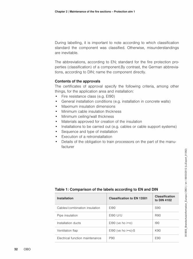
During labelling, it is important to note according to which classificationstandard the component was classified. Otherwise, misunderstandingsare inevitable.
The abbreviations, according to EN; standard for the fire protection pro-perties (classification) of a component.By contrast, the German abbrevia-tions, according to DIN; name the component directly.
Contents of the approvalsThe certificates of approval specify the following criteria, among otherthings, for the application area and installation:• Fire resistance class (e.g. EI90)• General installation conditions (e.g. installation in concrete walls)• Maximum insulation dimensions• Minimum cable insulation thickness• Minimum ceiling/wall thickness• Materials approved for creation of the insulation• Installations to be carried out (e.g. cables or cable support systems)• Sequence and type of installation• Execution of a retroinstallation• Details of the obligation to train processors on the part of the manu-
facturer
Table 1: Comparison of the labels according to EN and DIN
Installation Classification to EN 13501 Classificationto DIN 4102
Cables/combination insulation EI90 S90
Pipe insulation EI90 U/U R90
Installation ducts EI90 (ve ho i↔o) I90
Ventilation flap EI90 (ve ho i↔o)-S K90
Electrical function maintenance P90 E90
33OBO
05 B
SS
_Bra
ndsc
hutz
info
rmat
ion_
Eur
opa
| OB
O |
/ en
/ 06/
03/2
012
(LLE
xpor
t_01
392)
Chapter 2 | Maintenance of the fire sections – Protection aim 1
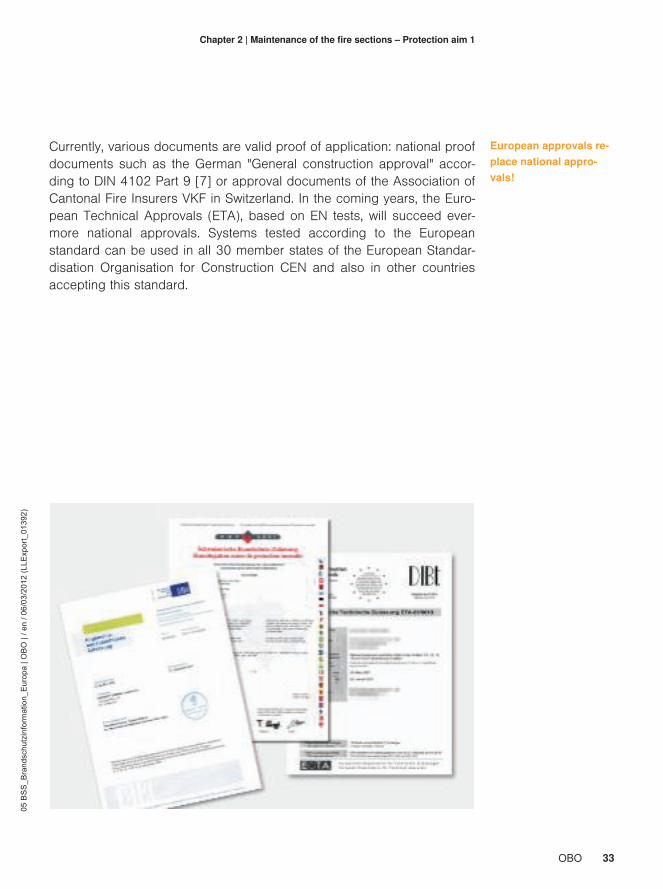
Currently, various documents are valid proof of application: national proofdocuments such as the German "General construction approval" accor-ding to DIN 4102 Part 9 [7] or approval documents of the Association ofCantonal Fire Insurers VKF in Switzerland. In the coming years, the Euro-pean Technical Approvals (ETA), based on EN tests, will succeed ever-more national approvals. Systems tested according to the Europeanstandard can be used in all 30 member states of the European Standar-disation Organisation for Construction CEN and also in other countriesaccepting this standard.
European approvals re-place national appro-vals!

34 OBO
05 B
SS
_Bra
ndsc
hutz
info
rmat
ion_
Eur
opa
| OB
O |
/ en
/ 06/
03/2
012
(LLE
xpor
t_01
392)
Chapter 2 | Maintenance of the fire sections – Protection aim 1
2.3.3 Obligation to labellingEach piece of insulation must be permanently labelled with a sign. Thislabelling must contain the following information:• Name of the erection engineer of the insulation (installation engineer)• Head office of the installation engineer• Insulation designation• Approval number, issued by the accredited testing office• Fire resistance class• Year of manufacture
The labelling is set against the background that the systems were con-structed and tested with different materials. The function of these materialcombinations has thus been proven. If systems are combined with othercomponents which do not belong to the system, then this can have a ne-gative impact on system behaviour if there is a fire. This must be avoi-ded. The requirement of the approval offices for processor training cour-ses is derived from this. It must be ensured that the processors know thebasic principles of construction law and are fully able to handle insulationmaterials.
Identification of the in-stalled system
35OBO
05 B
SS
_Bra
ndsc
hutz
info
rmat
ion_
Eur
opa
| OB
O |
/ en
/ 06/
03/2
012
(LLE
xpor
t_01
392)
Chapter 2 | Maintenance of the fire sections – Protection aim 1
Declaration of agreementAccording to the proof of applicability, a declaration of conformity mustbe completed for each piece of insulation installed. This certificate con-firms that the installed system corresponds to the conditions of the ap-proval and that the installation engineer has complied with all the specifi-cations. The confirmation should then be handed over to the client forpresentation to the construction authorities.

36 OBO
05 B
SS
_Bra
ndsc
hutz
info
rmat
ion_
Eur
opa
| OB
O |
/ en
/ 06/
03/2
012
(LLE
xpor
t_01
392)
Chapter 2 | Maintenance of the fire sections – Protection aim 1
2.4 Insulation systems, construction types
Solid walls and ceilings made of masonry and concrete as well as light-weight partition walls, built using dry construction methods, require ap-propriately suitable insulation measures.The installations which can passthrough can be made up of cables and cable support systems, combu-stible and non-combustible pipes or a combination of both. There are re-quirements, for example, for a dust- and fibre-free installation, destructi-on-free retroinstallation and certain gas pressure tightnesses.
Typical insulation systems consist of: mortar, mineral fibre plates withcoating, bags, local foam, single-component compounds, foams and fit-tings, boxes, silicones and modular insulation. All the systems possessspecial fire protection components, which fulfil a safe function in case offire in accordance with the testing standard.

37OBO
05 B
SS
_Bra
ndsc
hutz
info
rmat
ion_
Eur
opa
| OB
O |
/ en
/ 06/
03/2
012
(LLE
xpor
t_01
392)
Chapter 2 | Maintenance of the fire sections – Protection aim 1

38 OBO
05 B
SS
_Bra
ndsc
hutz
info
rmat
ion_
Eur
opa
| OB
O |
/ en
/ 06/
03/2
012
(LLE
xpor
t_01
392)
Chapter 2 | Maintenance of the fire sections – Protection aim 1
2.5 Applications and special applications
The testing standard for insulation systems defines standard applicationsin walls and ceilings. In most cases, the possible electrical and sanitaryinstallations are covered by the specifications of the standard. However,no two buildings are alike, meaning that applications may occur whichare not defined by the standard. Not only such deviations from the stan-dard, but also special cases, can only be interpreted through surveys. Of-ten, a report from the manufacturer is sufficient here, as they are able toevaluate whether an insulation material can also function with the appro-priate deviation. However, in some situations it can happen that, due tothe construction environment, a survey from an independent materials' te-sting institute is required. For positive measures, these provide a survey-or's report for the appropriate construction project. This ensures that boththe erection engineer and the operator of the building are then on thesafe side.
Survey for special appli-cations

39OBO
05 B
SS
_Bra
ndsc
hutz
info
rmat
ion_
Eur
opa
| OB
O |
/ en
/ 06/
03/2
012
(LLE
xpor
t_01
392)
Chapter 2 | Maintenance of the fire sections – Protection aim 1
2.6 Building in old buildings
The following applies to all old building ceilings and wall constructionsmade of special components (sandwich elements): Mounting of insulati-on systems is approved when this kind of application is included in theapproval. In conjunction with the construction authorities, systems can beused which, according to the approval, are approved for a similar appli-cation, e.g. within a layer of non-combustible materials. It is important be-fore mounting to always obtain the approval from the relevant authorities,e.g. construction supervision or fire brigade.
Important: obtain appro-val!
Wood beam ceiling soffit, made of non-combustible materials

40 OBO
05 B
SS
_Bra
ndsc
hutz
info
rmat
ion_
Eur
opa
| OB
O |
/ en
/ 06/
03/2
012
(LLE
xpor
t_01
392)
Chapter 3Protection of escape routes– Second protection aim
Approximately 95% of all deaths during fires are caused by smoke poiso-ning! In case of fire, emergency and escape routes are the central lifelineof the building and must remain usable under all circumstances.

41OBO
05 B
SS
_Bra
ndsc
hutz
info
rmat
ion_
Eur
opa
| OB
O |
/ en
/ 06/
03/2
012
(LLE
xpor
t_01
392)
Chapter 3 | Protection of escape routes – Second protection aim
3.1 What is an emergency and escape route? 42
3.2 Problem: Fire loads 43
3.3 Safe routing options3.3.1 Installation in false ceilings3.3.2 Shielding with plate material3.3.3 Cable routing in fire protection ducts
44
3.3.4 Bandaging of cable support systems
3.4 Proofs of applicability3.4.1 Tests3.4.2 Classifications and certificates
50
42 OBO
05 B
SS
_Bra
ndsc
hutz
info
rmat
ion_
Eur
opa
| OB
O |
/ en
/ 06/
03/2
012
(LLE
xpor
t_01
392)
Chapter 3 | Protection of escape routes – Protection aim 2
3.1 What is an emergency and escape route?
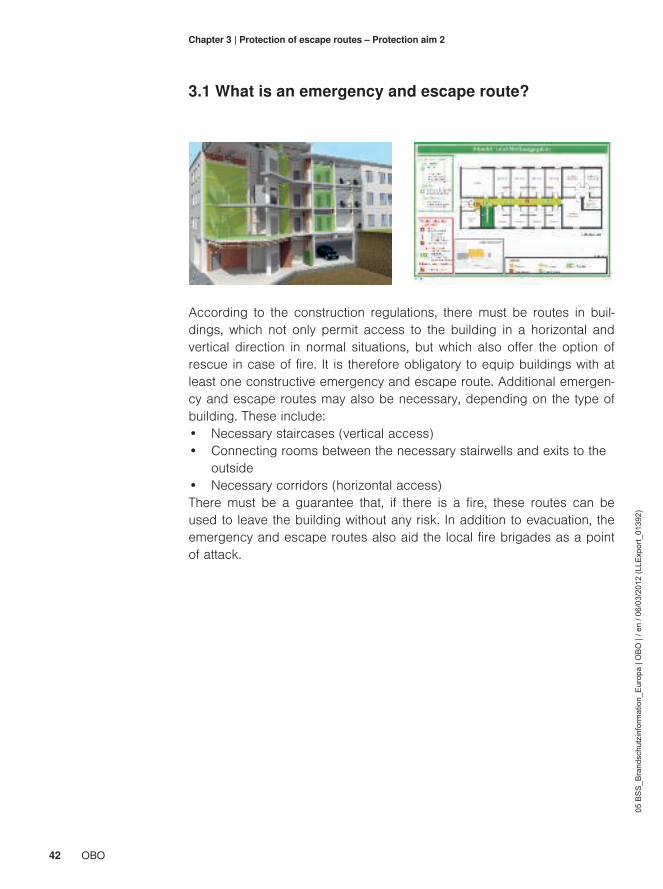
According to the construction regulations, there must be routes in buil-dings, which not only permit access to the building in a horizontal andvertical direction in normal situations, but which also offer the option ofrescue in case of fire. It is therefore obligatory to equip buildings with atleast one constructive emergency and escape route. Additional emergen-cy and escape routes may also be necessary, depending on the type ofbuilding. These include:• Necessary staircases (vertical access)• Connecting rooms between the necessary stairwells and exits to the
outside• Necessary corridors (horizontal access)There must be a guarantee that, if there is a fire, these routes can beused to leave the building without any risk. In addition to evacuation, theemergency and escape routes also aid the local fire brigades as a pointof attack.

43OBO
05 B
SS
_Bra
ndsc
hutz
info
rmat
ion_
Eur
opa
| OB
O |
/ en
/ 06/
03/2
012
(LLE
xpor
t_01
392)
Chapter 3 | Protection of escape routes – Second protection aim
3.2 Problem: Fire loads
In the area of emergency and escape routes, an installation may not po-se an additional fire load. This requirement can be fulfilled using an ap-propriate type of installation:• Concealed installation• Installation in fire protection duct systems• Installation above suspended fire protection ceilings• Use of non-combustible materials• Routing of cables with improved behaviour in case of fire
Protection aim: preven-tion of fire spread in thedirection of escape!
Fire loads through installations in emergency and escape routes arenot permitted!However, there are exceptions here: the cables required for the operationof an emergency and escape route may be routed in the open. The reas-on for this is that, for example, in a corridor made of combustible plastic,the risk of a fire through a small joint cable to supply a lamp is hardly in-creased. However, a massive volume of cables, routed openly in a corri-dor to supply other areas of the building, is not accepted. Systems testedand approved for fires must be installed here.
Behaviour of cables in case of fire: PVC-insulated, low-smoke, halogen-free (from left)

44 OBO
05 B
SS
_Bra
ndsc
hutz
info
rmat
ion_
Eur
opa
| OB
O |
/ en
/ 06/
03/2
012
(LLE
xpor
t_01
392)
Chapter 3 | Protection of escape routes – Second protection aim
3.3 Safe routing options
The option of open routing is not a problem with, for example, non-com-bustible sanitary pipes. It only becomes a problem when the sanitary pi-pes are jacketed with combustible insulation.In most corridors, the instal-lations of all the different networks meet: electrics, sanitation, ventilationand air-conditioning.The electrical installation is a special case as electri-city can ignite flammable materials, e.g. cable insulation and insulationlayers of pipes.
Under normal circumstances a correctly executed electrical installationwith a correctly selected wire cross-section, correct fuses and cables,which were not damaged during drawing in, would not be dangerous Therisk of a fire starting only occurs when the cables become too hot or theinsulation is damaged due to incorrect routing and dimensioning.
Electrical installation asa potential source ofignition
45OBO
05 B
SS
_Bra
ndsc
hutz
info
rmat
ion_
Eur
opa
| OB
O |
/ en
/ 06/
03/2
012
(LLE
xpor
t_01
392)
Chapter 3 | Protection of escape routes – Second protection aim
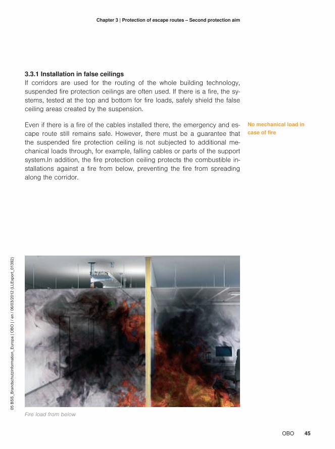
3.3.1 Installation in false ceilingsIf corridors are used for the routing of the whole building technology,suspended fire protection ceilings are often used. If there is a fire, the sy-stems, tested at the top and bottom for fire loads, safely shield the falseceiling areas created by the suspension.
Even if there is a fire of the cables installed there, the emergency and es-cape route still remains safe. However, there must be a guarantee thatthe suspended fire protection ceiling is not subjected to additional me-chanical loads through, for example, falling cables or parts of the supportsystem.In addition, the fire protection ceiling protects the combustible in-stallations against a fire from below, preventing the fire from spreadingalong the corridor.
No mechanical load incase of fire
Fire load from below

46 OBO
05 B
SS
_Bra
ndsc
hutz
info
rmat
ion_
Eur
opa
| OB
O |
/ en
/ 06/
03/2
012
(LLE
xpor
t_01
392)
Chapter 3 | Protection of escape routes – Second protection aim
The German MLAR directive permits only the following systems for elec-trical installations above suspended fire protection ceilings in the area ofemergency and escape routes:• Routing systems for function maintenance tested according to DIN
4102 Part 12 [8]• Special routing systems, tested for fire protection for this application.The strictly controlled system limits mean that function maintenance sy-stems can only be used with restrictions for this type of electrical installa-tion. In order to offer practical installation options for intermediate ceilingmounting, proofs for special routing systems with high load capacitiesand their deformation behaviour in case of fire are available.

47OBO
05 B
SS
_Bra
ndsc
hutz
info
rmat
ion_
Eur
opa
| OB
O |
/ en
/ 06/
03/2
012
(LLE
xpor
t_01
392)
Chapter 3 | Protection of escape routes – Second protection aim
3.3.2 Shielding with plate materialAn additional option for fireproof encapsulation of fire loads is to shieldinstallations with special plate material. For example, the entire cablesupport system is surrounded by fire protection plates. This type ofmounting is commonly used in old buildings. However, there may be nomechanical load on the plates requiring the installations to be securelyfastened against fire. This shielding is created at great effort by drywallengineers and insulation engineers on the construction site. In addition,these constructions must possess proof of applicability. Often, this is ageneral construction test certificate of a materials testing institute.
48 OBO
05 B
SS
_Bra
ndsc
hutz
info
rmat
ion_
Eur
opa
| OB
O |
/ en
/ 06/
03/2
012
(LLE
xpor
t_01
392)
Chapter 3 | Protection of escape routes – Second protection aim
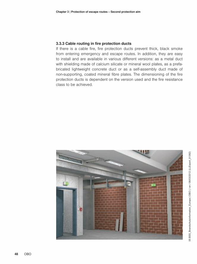
3.3.3 Cable routing in fire protection ductsIf there is a cable fire, fire protection ducts prevent thick, black smokefrom entering emergency and escape routes. In addition, they are easyto install and are available in various different versions: as a metal ductwith shielding made of calcium silicate or mineral wool plates, as a prefa-bricated lightweight concrete duct or as a self-assembly duct made ofnon-supporting, coated mineral fibre plates. The dimensioning of the fireprotection ducts is dependent on the version used and the fire resistanceclass to be achieved.
49OBO
05 B
SS
_Bra
ndsc
hutz
info
rmat
ion_
Eur
opa
| OB
O |
/ en
/ 06/
03/2
012
(LLE
xpor
t_01
392)
Chapter 3 | Protection of escape routes – Second protection aim
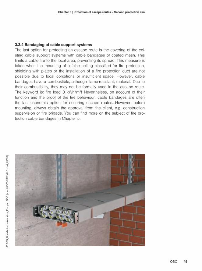
3.3.4 Bandaging of cable support systemsThe last option for protecting an escape route is the covering of the exi-sting cable support systems with cable bandages of coated mesh. Thislimits a cable fire to the local area, preventing its spread. This measure istaken when the mounting of a false ceiling classified for fire protection,shielding with plates or the installation of a fire protection duct are notpossible due to local conditions or insufficient space. However, cablebandages have a combustible, although flame-resistant, material. Due totheir combustibility, they may not be formally used in the escape route.The keyword is: fire load 0 kWh/m²! Nevertheless, on account of theirfunction and the proof of the fire behaviour, cable bandages are oftenthe last economic option for securing escape routes. However, beforemounting, always obtain the approval from the client, e.g. constructionsupervision or fire brigade. You can find more on the subject of fire pro-tection cable bandages in Chapter 5.

50 OBO
05 B
SS
_Bra
ndsc
hutz
info
rmat
ion_
Eur
opa
| OB
O |
/ en
/ 06/
03/2
012
(LLE
xpor
t_01
392)
Chapter 3 | Protection of escape routes – Second protection aim
3.4 Proofs of applicability
Fire protection plate constructions and intermediate ceiling systems withfire protection properties often possess general construction test certifi-cates and classification reports according to the relevant testing andclassification standards. There are various manufacturers and providersfor these. Fire protection ducts also possess this type of proof. However,the situation is rather different in the case of support systems above fireprotection ceilings. The requirements and tests are explained below.

51OBO
05 B
SS
_Bra
ndsc
hutz
info
rmat
ion_
Eur
opa
| OB
O |
/ en
/ 06/
03/2
012
(LLE
xpor
t_01
392)
Chapter 3 | Protection of escape routes – Second protection aim
3.4.1 TestsFire protection ducts are tested by an independent materials' testing insti-tute in accordance with DIN 4102 Part 11 [10]. The electrical cables areflamed within the duct.During the entire classified time, neither fire norsmoke may escape from the duct system. This provides effective and se-cure protection of an emergency and escape route against a cable fire.The fire load in the duct is effectively encapsulated.
A European testing standard for fire protection ducts is currently beingworked on. The standard makes a distinction between locally createdducts made of plate material and prefabricated ducts. It is not yet certainin which series of test standards the appropriate ducts will be included.

52 OBO
05 B
SS
_Bra
ndsc
hutz
info
rmat
ion_
Eur
opa
| OB
O |
/ en
/ 06/
03/2
012
(LLE
xpor
t_01
392)
Chapter 3 | Protection of escape routes – Second protection aim
To evaluate practical solutions in the sense of the directives for electricalinstallations above suspended fire protection ceilings, fire tests are car-ried out according to DIN 4102 Part 12 and Part 4 [10]. For example,the following solutions are tested:• Cable support systems for wall and ceiling mounting• Collecting clamps for wall and ceiling mounting• Metal pressure clips for ceiling mounting
Fire tests test the following requirements:• High mechanical load• Stability of the routing system• Deformation of the laying system
Requirements for falseceiling systems
Measuring units from the testing furnace Steel chains as replacement weights
53OBO
05 B
SS
_Bra
ndsc
hutz
info
rmat
ion_
Eur
opa
| OB
O |
/ en
/ 06/
03/2
012
(LLE
xpor
t_01
392)
Chapter 3 | Protection of escape routes – Second protection aim
The tests are carried out using the standard temperature-time curve(ETK), by simulating a full fire in an intermediate ceiling area. In most ca-ses, testing is carried out for a fire resistance length of 30 minutes, but inspecial cases a 90-minute test is carried out. The test results can beused to make statements on practical execution, e.g. on compliance ofspacing distances to the intermediate ceiling.
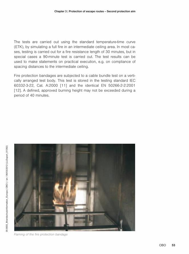
Fire protection bandages are subjected to a cable bundle test on a verti-cally arranged test body. This test is stored in the testing standard IEC60332-3-22, Cat. A:2000 [11] and the identical EN 50266-2-2:2001[12]. A defined, approved burning height may not be exceeded during aperiod of 40 minutes.
Flaming of the fire protection bandage
54 OBO
05 B
SS
_Bra
ndsc
hutz
info
rmat
ion_
Eur
opa
| OB
O |
/ en
/ 06/
03/2
012
(LLE
xpor
t_01
392)
Chapter 3 | Protection of escape routes – Second protection aim
3.4.2 Classifications and certificatesFire protection ducts for use in emergency and escape routes are classi-fied as I ducts according to DIN 4102 Part 11. There are I30 (fire-retar-dant) to I120 (fire-resistant) versions. According to the European Classifi-cation Standard EN 13501, ducts can have the properties EI90 (vehoi↔o) (see Chapter 2.3.2). Here, "veho i↔o" stands for the installation opti-ons: vertical and horizontal; tested and approved with a fire load from theinterior to the exterior and vice versa.Applicability is documented in a testreport from a material testing institute.
There is no testing standard for installations above fire protection ceilingsand thus no classification is possible. The test reports provide informati-on on the results. The tests are not subject to accreditation and can, inprinciple, be carried out and documented by the manufacturers themsel-ves. The documentation should contain all the relevant parameters, suchas the maximum mechanical loads, support spacing distances, securingmeasures and deformation behaviour. Such a system then fulfils con-struction law requirements, e.g. those of the cable system directive.

55OBO
05 B
SS
_Bra
ndsc
hutz
info
rmat
ion_
Eur
opa
| OB
O |
/ en
/ 06/
03/2
012
(LLE
xpor
t_01
392)
Chapter 3 | Protection of escape routes – Second protection aim
Besides a material classification, cable bandages also have an applicati-on approval. Additional proofs can be, for example, reports on the basisof an IEC test. These documents describe the proven function.
Fire protection bandages were developed, in order to prevent fires fromspreading within fire sections.Comparison with an I duct for use in emer-gency and escape routes is not possible.
Important! Cable banda-ges never fulfil the re-quirements for I ducts.
Logos of the testing institutes and approval offices: DIBt, iBMB, BET, IEC, GL, DIN

56 OBO
05 B
SS
_Bra
ndsc
hutz
info
rmat
ion_
Eur
opa
| OB
O |
/ en
/ 06/
03/2
012
(LLE
xpor
t_01
392)
Chapter 4Function maintenancefor electrical systems– Third protection aimIf there is a fire, emergency and escape routes must remain usable andimportant technical equipment, such as emergency lighting, fire alarm sy-stems and smoke extraction systems, continue to function.Therefore it isessential that the power supply for these systems is specially protected.In addition, certain technical systems must support the fire brigades infighting fires for a sufficiently long period of time.
57OBO
05 B
SS
_Bra
ndsc
hutz
info
rmat
ion_
Eur
opa
| OB
O |
/ en
/ 06/
03/2
012
(LLE
xpor
t_01
392)
Chapter 4 | Function maintenance for electrical systems – Third protection aim
4.1 What is electrical function maintenance? 58
4.2 Tasks of function maintenance 60
4.3 Proofs of applicability4.3.1 Tests4.3.2 Definition of a cable system4.3.3 Cables
61
4.3.4 Classifications and certificates
4.4 Installation types4.4.1 Standard support constructions4.4.2 Cable-specific laying types4.4.3 Installation situations
67
4.5 Special features of vertical routing 76
4.6 Function maintenance with fire protection ducts 80
4.7 Limits of function maintenance4.7.1 Unsuitable components4.7.2 Solution options
81
4.8 Fastenings 85

58 OBO
05 B
SS
_Bra
ndsc
hutz
info
rmat
ion_
Eur
opa
| OB
O |
/ en
/ 06/
03/2
012
(LLE
xpor
t_01
392)
Chapter 4 | Function maintenance for electrical systems – Third protection aim
4.1 What is electrical function maintenance?
Special cables and routing systems make it possible to maintain the sup-port of an electrical current in the case of fire, thus guaranteeing functionmaintenance. However, there are many misunderstandings here, whichcan be caused by different abbreviations. The following incorrect termsare often connected with function maintenance:• FE180• Non-combustible cables• Fireproof• Fireproof installation• Insulation maintenance• No smoke creation
In particular, the abbreviation "FE180" continually causes confusion.Alt-hough you might think otherwise, it does not stand for "Function mainte-nance for 180 minutes" but for "Flame impact time". The "flame impacttime" is a testing criterion according to DIN VDE 0472-814 [13] and IEC60331-11, -12 and -13 [14]. In this test, cable samples are subjected todirect flaming at a constant temperature of 750 °C for a period of 90 mi-nutes (IEC) or 180 minutes (VDE). During this time, none of the fusesmonitoring the individual wires may drop. This test of "insulation mainte-nance" may not, under any circumstances, be confused with the test ofthe electrical function maintenance of cable systems.

59OBO
05 B
SS
_Bra
ndsc
hutz
info
rmat
ion_
Eur
opa
| OB
O |
/ en
/ 06/
03/2
012
(LLE
xpor
t_01
392)
Chapter 4 | Function maintenance for electrical systems – Third protection aim
Where is function maintenance required?Technical equipment with function maintenance is required for the follo-wing buildings and systems:• Hospitals• Hotels and restaurants• Tower blocks• Meeting points• Commercial buildings• Closed large garages• Underground railway systems• Chemicals industry• Power stations• TunnelsThis could be because these constructions are regularly frequented bymany people. This creates an increased safety risk for gatherings of peo-ple. However, with certain systems, property and the environment mustalso be protected.
Function maintenance in construction regulationsThe requirement for electrical installations with function maintenance is acomponent part of the construction regulations. Function maintenanceonly relates to those areas which provide the power supply to safety-rele-vant systems, such as emergency lighting, alarm systems, fire alarm sy-stems and smoke extraction systems. Here, the regulations require thatthe power supply must be insured for a specific period of time, even ifthere is a fire.
Safety equipment requi-red by construction law
60 OBO
05 B
SS
_Bra
ndsc
hutz
info
rmat
ion_
Eur
opa
| OB
O |
/ en
/ 06/
03/2
012
(LLE
xpor
t_01
392)
Chapter 4 | Function maintenance for electrical systems – Third protection aim
4.2 Tasks of function maintenance
30 minutes: Function maintenance for a safe evacuation and rescueThe first 30 minutes after the start of a fire play an important role. For theaffected building to be cleared quickly, the function maintenance must beguaranteed for the following equipment during this time:• Safety lighting systems• Lifts with fire control• Fire alarm systems• Alarm systems and systems to issue instructions• Fire extraction systems
90 minutes: Function maintenance for effective fire-fightingTo support fire-fighting operations, it is imperative that certain technicalequipment is supplied with sufficient power even up to 90 minutes after afire breaks out in a building. This equipment includes:• Water pressure increase systems for fire water supply• Mechanical smoke extraction systems and smoke protection pressu-
re systems• Fire brigade lifts• Bed lifts in hospitals and similar equipment

61OBO
05 B
SS
_Bra
ndsc
hutz
info
rmat
ion_
Eur
opa
| OB
O |
/ en
/ 06/
03/2
012
(LLE
xpor
t_01
392)
Chapter 4 | Function maintenance for electrical systems – Third protection aim
4.3 Proofs of applicability
4.3.1 Tests
Fire testThe proof of the function maintenance of electrical installation materialmust be obtained by a fire test, carried out by an independent materials'testing agency. There is currently no European standard on functionmaintenance, but there are some national test regulations. The most wi-dely spread and accepted is testing according to DIN 4102 Part 12.
The test body, i.e. the cable system, must have a testing length of atleast 3,000 mm and is installed in a special oven. The cables are routedon the support systems. According to the standard, two testing cables ofthe same type are used. In order to cover a cross-sectional range in atest, the smallest and largest desired wire cross-section are tested. Inmost cases, 50 mm² of copper is chosen for the largest cross-section,which, subject to agreement between all the testing institutes, covers allthe cross-sections above it with sufficient safety.
The test voltages are 400 V for the power cable types (e.g. NHXH) and110 V for data and telecommunications cables (e.g. of types JE-H(St)H).The test criteria is: no failure of the cables through short-circuits or con-ductor breaks through the required testing time.
Function maintenance test structure Testing furnace of a materials' testing institute(MPA)

62 OBO
05 B
SS
_Bra
ndsc
hutz
info
rmat
ion_
Eur
opa
| OB
O |
/ en
/ 06/
03/2
012
(LLE
xpor
t_01
392)
Chapter 4 | Function maintenance for electrical systems – Third protection aim
4.3.2 Definition of a cable systemA cable system with integrated function maintenance is, according to DIN4102 Part 12, the combination of the laying system (cable ladder, cabletray, etc.) and cables with integrated function maintenance.

63OBO
05 B
SS
_Bra
ndsc
hutz
info
rmat
ion_
Eur
opa
| OB
O |
/ en
/ 06/
03/2
012
(LLE
xpor
t_01
392)
Chapter 4 | Function maintenance for electrical systems – Third protection aim
System labelling by the erection engineerEach cable system must be permanently labelled with a sign. This label-ling must contain the following information:• Name of the erection engineer of the cable system (installation engi-
neer)• Function maintenance class "E" or "P"• Number of the test certificate• Owner of the test certificate• Year of manufacture
Labelling of a cable system

64 OBO
05 B
SS
_Bra
ndsc
hutz
info
rmat
ion_
Eur
opa
| OB
O |
/ en
/ 06/
03/2
012
(LLE
xpor
t_01
392)
Chapter 4 | Function maintenance for electrical systems – Third protection aim
4.3.3 Cables
Extreme loads for cablesIf there is a fire, the cables and conductors are subjected to extremeloads from flames and heat.Cables used for a function maintenance in-stallation must be able to withstand temperatures of up to 1,000 °C andhigher for a specific period of time, without there being a short-circuit ofthe copper conductors. As the copper conductor may begin to anneal atthese extreme temperatures, thus impairing its own mechanical stability,the support system serving as a "support corset" has a special significan-ce.
Cables with integrated function maintenanceTherefore, in the case of cables with integrated function maintenance, theinsulation has a special role to play. A distinction is made between twodifferent construction types: on the one hand, special coils around thecopper conductor made of fibre glass or mica type, on the other, specialceramising plastic insulations.If there is a fire, then, with cables with special coils of fibre glass or micatape, the cable insulation burns completely, creating a layer of ash. Thisis kept together by the windings and ensures that the copper conductorsare kept apart and that no short-circuit of the support system can takeplace.More modern cable types use special ceramising plastic insulation inste-ad of the coils. The main component of the insulation is aluminium hydro-xide, which forms a soft ceramic sleeve when it burns. This creates thedesired insulation of the wires carrying current, both between each otherand also to the support system.
Function maintenance cable with insulating ashlayer
The copper conductors remain separate fromone another – no short-circuit is created.

65OBO
05 B
SS
_Bra
ndsc
hutz
info
rmat
ion_
Eur
opa
| OB
O |
/ en
/ 06/
03/2
012
(LLE
xpor
t_01
392)
Chapter 4 | Function maintenance for electrical systems – Third protection aim
Halogen-free plasticHalogen-free plastic is always used for the manufacture of cables with in-tegrated function maintenance. This plastic does not contain any chlori-ne, bromine or fluorine and does not create any corrosive fire gases du-ring combustion. This is proven through the combustion of the insulationmaterial and measurement of the pH value and the conductivity accor-ding to EN 50267-2, -3 [15] and IEC 60754-2 [16].
Low-smoke and reduced fire spreadingIn addition, cables with integrated function maintenance have additionalpositive characteristics in case of fire. These include:• Low-smoke combustion• Reduced fire spreadingThese additional properties are also checked using fire tests on cablesamples. The smoke density is measured according to IEC 61034-1, -2[17] and EN 61034-1, -2 [18]. The light intensity is measured using pho-toelectrics, whereby the minimum value may not fall below 60 per cent ofthe nominal output of the light source due to the smoke.
Cables can also helpwith fire protection!
The spread of fires is tested in a vertical arrangement according to EN50266-2-4 [19] and IEC 60332-3-24 Cat. C [20]. Cable bundles are fla-med on a vertical section. After the prescribed length of 20 minutes, theflames must go out by themselves and there may be no damage up to2.5 m above the burner.

66 OBO
05 B
SS
_Bra
ndsc
hutz
info
rmat
ion_
Eur
opa
| OB
O |
/ en
/ 06/
03/2
012
(LLE
xpor
t_01
392)
Chapter 4 | Function maintenance for electrical systems – Third protection aim
4.3.4 Classifications and certificatesThe result of the fire test is documented in a construction test certificate.For cable systems with cable-specific support constructions, this test cer-tificate is considered the proof of function maintenance. In addition to thetest certificate, for standard support structures, a surveyor's commentsare required as proof of function maintenance.
Depending on the length of time achieved, the cable systems are assi-gned to the classes E30 to E90 according to DIN. According to the Euro-pean classification standard EN 13501, a cable system is given the ab-breviation "P" with the appropriate time in minutes after a successfullycompleted test.
Together, the cablesand the routing systemform a single unit.
Function maintenance classes according to DIN 4102 Part 12
Testing length Short code Division into function maintenance classes
30 minutes E30 Function maintenance at least 30 minutes
60 minutes E60 Function maintenance at least 60 minutes
90 minutes E90 Function maintenance at least 90 minutes

67OBO
05 B
SS
_Bra
ndsc
hutz
info
rmat
ion_
Eur
opa
| OB
O |
/ en
/ 06/
03/2
012
(LLE
xpor
t_01
392)
Chapter 4 | Function maintenance for electrical systems – Third protection aim
4.4 Installation types
There are various routing options for routing cables with integrated functi-on maintenance. Besides the type and number of cables to be routed,economic aspects are naturally also of importance. There are many va-riations, from the tried and trusted standard support structures with whichplanning is possible, irrespective of the cable type, right through to eco-nomical cable-specific solutions.

68 OBO
05 B
SS
_Bra
ndsc
hutz
info
rmat
ion_
Eur
opa
| OB
O |
/ en
/ 06/
03/2
012
(LLE
xpor
t_01
392)
Chapter 4 | Function maintenance for electrical systems – Third protection aim
4.4.1 Standard support constructionsThe standard specifies that not just the cables themselves belong to thefunction maintenance of an electrical cabling system but also the routingsystems. With standard support structures, it is possible to select the ca-bles required for the installation freely. This is possible, as all the cablemanufacturers have proved the function maintenance of their cables andconductors for the standard support systems.
DIN 4102 Part 12 defines three standard routing systems:• Routing on cable ladders• Routing on cable trays• Individual cable routing under the ceiling
Individual cable routing under the ceiling comprises the following routingtypes:• Individual clips• Profile rails• Clamp clips with and without long troughs.
The parameters of the horizontal routing types were transferred to verticalinstallations, making vertical sections possible.
Specified routing types

69OBO
05 B
SS
_Bra
ndsc
hutz
info
rmat
ion_
Eur
opa
| OB
O |
/ en
/ 06/
03/2
012
(LLE
xpor
t_01
392)
Chapter 4 | Function maintenance for electrical systems – Third protection aim
Table 3: Parameters of the standard support structures: cable traysand ladders
Cable trays Cable ladders Rising sections
Fastening spacings [m] 1,2 1,2 1,2
Maximum width [mm] 300 400 600
Maximum cable load [kg/m] 10 20 20
Maximum number of layers 6 3 1
Threaded rod locking Yes Yes -

70 OBO
05 B
SS
_Bra
ndsc
hutz
info
rmat
ion_
Eur
opa
| OB
O |
/ en
/ 06/
03/2
012
(LLE
xpor
t_01
392)
Chapter 4 | Function maintenance for electrical systems – Third protection aim
The benefits• Free cable selection, as the combinations of cables and standard
support structures possess proof of applicability.• No binding to specific cable types.• The structures are ideal for smaller projects.• Testing means that the countless installation variants are approved
for many years.
Summary: Here, the installation engineer can "play it safe".
Table 4: Parameters of the standard support structures: individual routing with clips
Individu-al clips
Clamp clipswithout longtroughs
Clamp clips withlong troughs
Horizontal fastening spacings [cm] 30 30 60
Vertical fastening spacings [cm] 30 30 -
Maximum cable diameter [mm] Unlimited Unlimited Unlimited
Maximum bundle diameter [mm] 3 x 25 3 x 25 3 x 25

71OBO
05 B
SS
_Bra
ndsc
hutz
info
rmat
ion_
Eur
opa
| OB
O |
/ en
/ 06/
03/2
012
(LLE
xpor
t_01
392)
Chapter 4 | Function maintenance for electrical systems – Third protection aim
4.4.2 Cable-specific support systemsCable-specific support systems require specific cables. Any proof is onlyvalid for the actually tested combination of laying variant and cable. The-re are many tested combinations. With these systems, economical rou-ting is paramount. Thus, they differ considerably from standard supportconstructions. Cable-specific systems differ from the standard, e.g. in thefastening spacing distances of the clips. Fastening spacing distances of80 cm are no rarity with specific cable types.
Make routing more eco-nomical
When cables are routed on cable trays, the support spacing distancesand load capacities are increased.In addition, with some systems there isno need for the attachment of a threaded rod lock near the bracket tip.The great advantage of this is that cables need not be threaded throughon retroinstallation.

72 OBO
05 B
SS
_Bra
ndsc
hutz
info
rmat
ion_
Eur
opa
| OB
O |
/ en
/ 06/
03/2
012
(LLE
xpor
t_01
392)
Chapter 4 | Function maintenance for electrical systems – Third protection aim
The benefits• Low material and mounting costs.• Planned systems: Support systems are clearly assigned to defined
cable types.• Large selection of approved cable types. • Ideal for larger buildings (project business).
Summary: Here, the possibilities of the combination of cables andsupport systems can be fully exploited – the systems are optimisedfor the appropriate application.

73OBO
05 B
SS
_Bra
ndsc
hutz
info
rmat
ion_
Eur
opa
| OB
O |
/ en
/ 06/
03/2
012
(LLE
xpor
t_01
392)
Chapter 4 | Function maintenance for electrical systems – Third protection aim
The following cable-specific support systems can be considered for aneconomical electrical installation with function maintenance.• Cable trays with and without threaded rod locking• Mesh cable trays• Cable ladders• Individual clips• Collecting clamps• Pressure clips• Electrical installation pipes in proven variants
Note:When choosing products approved for function maintenance, the specifi-cations of the planner and the details of the test certificates must be ob-served. The test certificates contain all the parameters on mounting andthe applicable components. It must be guaranteed that the cables usedwith the support system are tested and approved.Data for cable cross-sections, distances and maximum loads may varydepending on the cable type and cable manufacturer. The maximum ap-proved cable load may not be exceeded during installation. Even in thecase of retroinstallation in cable-specific routing types, the approved ca-ble types must be observed.
Cable trays RKSM Grip M collecting clamps

74 OBO
05 B
SS
_Bra
ndsc
hutz
info
rmat
ion_
Eur
opa
| OB
O |
/ en
/ 06/
03/2
012
(LLE
xpor
t_01
392)
Chapter 4 | Function maintenance for electrical systems – Third protection aim
4.4.3 Installation situationsLocal factors on the construction site sometimes require specific adapta-tions, in order to prevent or compensate the cable system from being ne-gatively influenced by surrounding components.
Observe local factors!
Space with plenty of girdersIf there are height jumps, the installed cables must be supported. Thismay be required when cables with large cross-sections are no longer onthe support system. For this, additional profile rails or brackets could bemounted, in order to accept the cable load.
Combination with other systemsVentilation systems, pipes, etc. may not be installed above the electricalinstallation with function maintenance, as parts may fall down if there is afire, damaging function maintenance cables. For this, function maintenan-ce cables must be placed directly under the ceiling or on the wall.

75OBO
05 B
SS
_Bra
ndsc
hutz
info
rmat
ion_
Eur
opa
| OB
O |
/ en
/ 06/
03/2
012
(LLE
xpor
t_01
392)
Chapter 4 | Function maintenance for electrical systems – Third protection aim
Limited spaceTwo solutions are suitable when space is limited. For example, cablescan be mounted directly under the ceiling with clips or pressure clips. Al-ternatively, it is possible to install several narrow tracks, one above theother, instead of one wide track.
Problematic substrateThe supporting force of old ceiling constructions cannot be determinedreliably. Therefore, wall mounting is recommended (e.g. for restorationprojects).

76 OBO
05 B
SS
_Bra
ndsc
hutz
info
rmat
ion_
Eur
opa
| OB
O |
/ en
/ 06/
03/2
012
(LLE
xpor
t_01
392)
Chapter 4 | Function maintenance for electrical systems – Third protection aim
4.5 Special features of vertical routing
Cables on rising sections must be effectively supported in the transferarea between vertical and horizontal routing, to prevent bending or sli-ding. Continuous cable systems only receive the appropriate functionmaintenance classification when there is effective support at a spacing ofmax. 3.5 m.

77OBO
05 B
SS
_Bra
ndsc
hutz
info
rmat
ion_
Eur
opa
| OB
O |
/ en
/ 06/
03/2
012
(LLE
xpor
t_01
392)
Chapter 4 | Function maintenance for electrical systems – Third protection aim
Strain relief through loopsTo ensure that cables do not break through their own weight during a fi-re, DIN 4102 Part 12 requires that they be routed in loops. The maxi-mum permitted distance between the individual loops is 3.5 m. The mini-mum length of the horizontally routed cables is 0.3 m. The horizontal fa-stening clips must, as with vertical mounting, also be mounted every 0.3m.In addition, during the installation the permissible bending radii of thecables mist be observed. However, in practice, this variant may often notbe used due to the large amount of space required at the side.
If there is a fire, the cables form an insulating ash layer and depositthemselves on the sides of the clip elements. This prevents the cablesfrom breaking on account of the copper weight.

78 OBO
05 B
SS
_Bra
ndsc
hutz
info
rmat
ion_
Eur
opa
| OB
O |
/ en
/ 06/
03/2
012
(LLE
xpor
t_01
392)
Chapter 4 | Function maintenance for electrical systems – Third protection aim
Strain relief through cable insulationAn additional strain relief option is the installation of approved cable insu-lations in the ceiling openings. In so doing, the fire resistance length ofthe insulation system must correspond to the function maintenance classof the installed cable system. In such cases, the storey height may notexceed 3.5 m. If there is a fire, the copper weight is caught by the seriesof clips located directly above the insulation, as this remains sufficientlycool due to the insulation function. The cables are clamped according tothe regulations and, at a storey height of maximum 3.5 m, "only" supporta permitted weight of 3.5 m of copper.

79OBO
05 B
SS
_Bra
ndsc
hutz
info
rmat
ion_
Eur
opa
| OB
O |
/ en
/ 06/
03/2
012
(LLE
xpor
t_01
392)
Chapter 4 | Function maintenance for electrical systems – Third protection aim
Effective support through proven clip designThe boxes, made of a non-combustible material with integrated mineral fi-bre insulation and which are mounted directly over a series of clips, haveproven their worth as a practical solution. This allows avoidance of thedifficult loops according to DIN 4102 Part 12.The action principle is similar to that of the cable insulation in the storeyceiling: if there is a fire, the series of clips in the box remains relativelycold and the cables remain clamped, preventing breaking. This solutionis approved for all types of vertical ladder and also for individual clips,which carry vertical cables. As ladder rungs can be penetrated, mountingis also possible in existing, continuous rising sections.Due to the independence of specific cable types or manufacturers, DIN-conformant and effective support of the vertically installed function main-tenance cables can be achieved in a way which is extremely economicand space-saving.

80 OBO
05 B
SS
_Bra
ndsc
hutz
info
rmat
ion_
Eur
opa
| OB
O |
/ en
/ 06/
03/2
012
(LLE
xpor
t_01
392)
Chapter 4 | Function maintenance for electrical systems – Third protection aim
4.6 Function maintenance with fire protection ducts
Electrical function maintenance can not only be achieved through cablesystems according DIN 4102 Part 12, but also through cable ducts. Thedifferent construction types of the ducts ensure that the cables routed inthe interior continue to function in a fire on the outside. This is ensuredusing different insulation materials.
The advantage of fire protection ducts is that, instead of special functionmaintenance cables, standard PVC-insulated cables can be routed. Ascables with integrated function maintenance are usually created with anominal voltage of 0.6/1 kV, there are no options in the field of cable sy-stems for routing medium-voltage cables with function maintenance, forexample.However, these cable types can be routed in fire protectionducts without risking the protection aim of the safe supply of a safety-re-levant system.

81OBO
05 B
SS
_Bra
ndsc
hutz
info
rmat
ion_
Eur
opa
| OB
O |
/ en
/ 06/
03/2
012
(LLE
xpor
t_01
392)
Chapter 4 | Function maintenance for electrical systems – Third protection aim
4.7 Limits of function maintenance
Not only neighbouring installations can have a negative impact on electri-cal function maintenance.Insufficient knowledge of local factors or evenincorrect planning can quickly limit implementation of function maintenan-ce in accordance with the approval. It is rare to find a technical buildingmanager coordinating fire protection measures on construction sites. Assuch, networks are often managed by different planners and installationengineers and only poorly matched.If architects and construction engineers do not employ technical buildingmanagers, then they must assume the coordination of fire protection me-asures themselves. But planners of technical building equipment will, infuture, have to expand their knowledge of construction and system fireprotection.
4.7.1 Unsuitable componentsIn many cases, the building structure often does not permit functionmaintenance routing which is conformant with the approval. Componentsclosing rooms, such as walls and ceilings, but which do not have a sup-porting function in the case of fire, are unsuitable for fastening cable sy-stems with integrated function maintenance according to DIN 4102 Part12. Dry-construction walls with metal stand constructions with a fire pro-tection-classified version are the best example of this. The structure ofthese walls means that a spread load, such as a cable tray, cannot bemounted. If there is a fire, then the structure of the normally plasterboardplates becomes brittle and breaks away from the subconstruction. So-called sandwich elements behave in a similar way. These are sheet steelwalls with a polyurethane foam insulation. They have no fire resistanceand are thus unsuitable for a fastening substrate for function maintenan-ce.
Only supportive compo-nents permit functionmaintenance.

82 OBO
05 B
SS
_Bra
ndsc
hutz
info
rmat
ion_
Eur
opa
| OB
O |
/ en
/ 06/
03/2
012
(LLE
xpor
t_01
392)
Chapter 4 | Function maintenance for electrical systems – Third protection aim
However, the greatest problems are caused by buildings or halls with asteel support construction, panelling with sandwich elements (as descri-bed above) and a roof of trapezoidal plates. Unprotected steel has no fi-re resistance length. At a temperature of 500 °C, which can be reachedvery quickly during a full fire, it only retains half its strength. As such, fa-stening of function maintenance routing to steel is not possible. In order to protect the building structure against premature failure in caseof fire, steel fire protection is usually created in the form of plate panel-ling or coatings. If something is to be fastened to these protected steelgirders, then the panelling or coatings must ultimately be destroyed. Theappropriate corrective work is often very difficult.
Even worse than steel girders are roofs made of trapezoidal plates. If the-re is a fire, hot fire gases rise, create a "ceiling jet", which distributes thefire smoke throughout the whole building at great speed.At the sametime, the thermals of the fire gases draw a lot of oxygen from the environ-ment into the fire, fanning the fire further through the draught.These ope-rations cause the temperatures under the ceiling to rise very quickly. Thisquickly causes a loss of strength in the thin trapezoid plates.Installationsattached to the ceiling would then fall down at an early stage of the fire.
Temperaturerhöhung durch Rauchausbreitung

83OBO
05 B
SS
_Bra
ndsc
hutz
info
rmat
ion_
Eur
opa
| OB
O |
/ en
/ 06/
03/2
012
(LLE
xpor
t_01
392)
Chapter 4 | Function maintenance for electrical systems – Third protection aim
4.7.2 Solution optionsThe simplest solution for mounting function maintenance in accordancewith the approval, is to arrange the systems above other components. Ifthere is a fire, no surrounding components may fall onto safety-relevantequipment fastened to the raw ceiling or the highest point on the wall.This protects function maintenance against negative impacts.
If other fire protection problems of a building are known, then systemsafety for people and the environment can be achieved using compensa-tion measures.Firstly, the protection aims to be achieved must be defi-ned.The higher the aims, the more comprehensive the necessary fire pro-tection measures will be.A simple option for implementing function maintenance is, for example,routing cables through non-endangered areas. If no function maintenan-ce cable tray can be fastened to a steel girder, then this area must bebypassed and a different route to the installation must be found. This canbe done, for example, through routing in the earth outside the building.

84 OBO
05 B
SS
_Bra
ndsc
hutz
info
rmat
ion_
Eur
opa
| OB
O |
/ en
/ 06/
03/2
012
(LLE
xpor
t_01
392)
Chapter 4 | Function maintenance for electrical systems – Third protection aim
Despite matching with all the offices involved in construction, fasteningon steel girders can be the only option for mounting function maintenan-ce. This deviation from the approved mounting substrate can be com-pensated through technical measures. These include smoke/heat extrac-tors (RWA), sprinkler systems or full monitoring through a fire alarm sy-stem.
If these technical measures are implemented, then it is necessary to do-cument them in the fire protection concept of the construction system. Inthe case of larger buildings, the fire protection concept is a componentpart of the construction approval and thus obligatory. It is important thatthe protection aims for the building are achieved, even if there are devia-tions from construction and system requirements.
Deviating solutionsmust be documented.
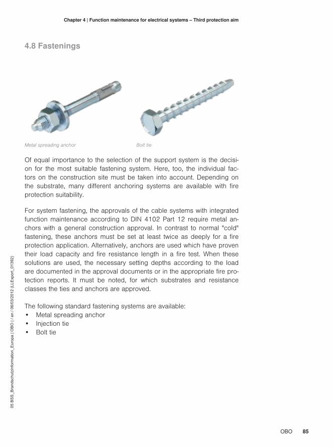
85OBO
05 B
SS
_Bra
ndsc
hutz
info
rmat
ion_
Eur
opa
| OB
O |
/ en
/ 06/
03/2
012
(LLE
xpor
t_01
392)
Chapter 4 | Function maintenance for electrical systems – Third protection aim
4.8 Fastenings
Metal spreading anchor Bolt tie
Of equal importance to the selection of the support system is the decisi-on for the most suitable fastening system. Here, too, the individual fac-tors on the construction site must be taken into account. Depending onthe substrate, many different anchoring systems are available with fireprotection suitability.
For system fastening, the approvals of the cable systems with integratedfunction maintenance according to DIN 4102 Part 12 require metal an-chors with a general construction approval. In contrast to normal "cold"fastening, these anchors must be set at least twice as deeply for a fireprotection application. Alternatively, anchors are used which have proventheir load capacity and fire resistance length in a fire test. When thesesolutions are used, the necessary setting depths according to the loadare documented in the approval documents or in the appropriate fire pro-tection reports. It must be noted, for which substrates and resistanceclasses the ties and anchors are approved.
The following standard fastening systems are available:• Metal spreading anchor• Injection tie• Bolt tie

86 OBO
05 B
SS
_Bra
ndsc
hutz
info
rmat
ion_
Eur
opa
| OB
O |
/ en
/ 06/
03/2
012
(LLE
xpor
t_01
392)
Chapter 4 | Function maintenance for electrical systems – Third protection aim
Wood beam ceiling in existing building
The main differences between the fastenings are in the suitable fasteningsubstrates and load classes. While most anchors are suitable and appro-ved for use in concrete, there are also special solutions for various ma-sonry types, even for hollow brick or porous concrete.With metal sprea-ding anchors, certain spacing distances must be guaranteed, e.g. to theedge of a component. As metal spreading anchors develop lateral forceswhen subjected to loads, break-outs may occur when the prescribedspacing distances are not complied with. By contrast, bolt ties can beplaced very close to the edge, as they do not create any lateral forces.
Dry construction walls are, as already described, particularly problematic.Due to their structure, it is not physically possible to fasten installations tothem securely for fire protection. Walls and ceilings in old existing buil-dings are an additional obstacle. Due to their construction, these can of-ten not be allocated to fire resistance classes. In such cases, so-calledextraction experiments are often required, in order to determine the resi-stance and load capacity of the construction.
Dry construction is notsupportive.


88 OBO
05 B
SS
_Bra
ndsc
hutz
info
rmat
ion_
Eur
opa
| OB
O |
/ en
/ 06/
03/2
012
(LLE
xpor
t_01
392)
Chapter 5Additional protection aims
A building or a construction system must not only fulfil the constructionrequirements for resistance and traffic safety.There will also be additionalrequirements from other areas.System operators naturally have a greatinterest in guaranteeing the safety and availability of their system. Thisoverlaps with the interests of the insurance companies: the more measu-res are implemented with regard to safe use, the lower the costs of therisk coverage conditions will normally be.

89OBO
05 B
SS
_Bra
ndsc
hutz
info
rmat
ion_
Eur
opa
| OB
O |
/ en
/ 06/
03/2
012
(LLE
xpor
t_01
392)
Chapter 5 | Additional protection aims
5.1 Protection of property and the environment 90
5.2 Industrial fire protection5.2.1 Fire alarm systems5.2.2 Extinguishing systems5.2.3 Prevention of fire spread
91

90 OBO
05 B
SS
_Bra
ndsc
hutz
info
rmat
ion_
Eur
opa
| OB
O |
/ en
/ 06/
03/2
012
(LLE
xpor
t_01
392)
Chapter 5 | Additional protection aims
5.1 Protection of property and the environment
The protection of property includes not only the protection of the buildingor the system, but also the protection of cultural goods and irreplaceabledata. With regard to environmental protection, the German MBO prescri-bes a special protection aim: "Public safety and order as well as life, he-alth and the natural basics of life (may) not be endangered." In otherwords, environmental protection must also be observed when implemen-ting fire protection measures. A system must be designed in such a waythat, in case of fire, neither people nor nature are endangered unneces-sarily.

91OBO
05 B
SS
_Bra
ndsc
hutz
info
rmat
ion_
Eur
opa
| OB
O |
/ en
/ 06/
03/2
012
(LLE
xpor
t_01
392)
Chapter 5 | Additional protection aims
5.2 Industrial fire protection
Of course, in industrial systems, construction fire protection requirementsmust also be implemented. Also, in most cases, such systems require afire protection concept, without which the system cannot be approved.Besides the aspect of safety for those people working in the machine,the operator must also focus on the protection of the machines, productand warehouse facilities. These points are also of importance for powergeneration. Protection of the usually very high investments in plant valuesis the main argument.
5.2.1 Fire alarm systemsThe risk evaluation and risk analysis of a system can lead to the con-struction authorities to require the erection of an all-covering fire protecti-on system before an approval is issued. The fire alarm system mustmatch the operative risks: the triggering elements should be selected ac-cording to the risk to be expected. If smoke development is to be expec-ted, then the characteristic value for the fire alarm is "smoke". Additionaltrigger characteristics such as flames or aerosols are also available.
Technician systems forearly fire detection
Networked fire alarm systems, which must function for 30 minutes accor-ding to construction law, can be achieved using different technologies.However, they all share the fact that additional technical systems arecontrolled via the alarm systems and can be run in a state which doesnot pose a risk to people. These include fire controllers for lifts, voicealarm systems and the triggering of extinguishing systems.

92 OBO
05 B
SS
_Bra
ndsc
hutz
info
rmat
ion_
Eur
opa
| OB
O |
/ en
/ 06/
03/2
012
(LLE
xpor
t_01
392)
Chapter 5 | Additional protection aims
5.2.2 Extinguishing systemsNot only the fire alarm system, as a detector and trigger unit, but also thetechnical extinguishing systems are an important component of preventi-ve fire protection. The risk analysis means that various systems are usedaccording to the combustible substances. These determine the type ofthe extinguishing agent and thus the design of the extinguishing system.Thus, a distinction is made between water extinguishing systems such assprinkler and spray mist systems, foam extinguishing systems and gasextinguishing systems. Gas extinguishing systems are often used forelectrical systems, as electrical current, together with the conductivity ofthe extinguishing water, would pose a considerable danger to those in-volved and the rescue services.However, one has to point out that using "smaller solutions" can alsoachieve considerable effects. Even wall hydrants and hand fire extinguis-hers (which are part of the statutory requirements for construction sy-stems) can be used for fires for the self-help of employees and the firebrigade.

93OBO
05 B
SS
_Bra
ndsc
hutz
info
rmat
ion_
Eur
opa
| OB
O |
/ en
/ 06/
03/2
012
(LLE
xpor
t_01
392)
Chapter 5 | Additional protection aims
5.2.3 Prevention of fire spreadIn the field of construction, a lot of emphasis is placed on the use of non-combustible substances and components. In addition, systems are arran-ged in such a way that fire sections of manageable size can be formedaccording to the risks. Spatial separation through construction measuresis a very effective measure in the prevention of the spread of fires toother areas of buildings and systems.If structural separation is not possible, other measures can be used. Forexample, installations can be safely shielded with plate material or routedin fire protection ducts. Coatings can be applied to supports and canform an insulation layer in case of fire. Thus, it is possible to increase thefire resistance capacity of these components.
Protected bridging of the fire wall using a fire protection bandage

94 OBO
05 B
SS
_Bra
ndsc
hutz
info
rmat
ion_
Eur
opa
| OB
O |
/ en
/ 06/
03/2
012
(LLE
xpor
t_01
392)
Chapter 5 | Additional protection aims
Cable systems can also be equipped to provide fire protection. Insteadof applying coatings to the cables, cable bandages can help to provide ashield. These protect the environment against a cable fire, as the coatingfoams up when there is a short-circuit, suffocating the fire.When flamed from outside, the cable systems protected in this way arethen excluded from the fire, as the combustible insulation of the cable isshielded from the environment. This function to prevent the spread of fi-res is tested in a fire test according to IEC 60332-3-22 Cat. A [21] usinga vertical arrangement of bandaged cable bundles. Various bandage ty-pes are available, e.g. for dry use in interior areas or external use in ag-gressive atmospheres.Thus, in photovoltaics, fire walls can be bridged with combustible ca-bles.Cable bandages are also used in wind power plants, even in offsho-re areas, as they reduce the feared chimney effect in a fire and thus limitthe damage. Fire brigades are scarcely able to fight fires in the gondolaof a wind power plant with an average height of 90 to 100 metres.
Coatings and cable ban-dages
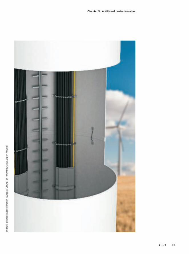
95OBO
05 B
SS
_Bra
ndsc
hutz
info
rmat
ion_
Eur
opa
| OB
O |
/ en
/ 06/
03/2
012
(LLE
xpor
t_01
392)
Chapter 5 | Additional protection aims
96 OBO
05 B
SS
_Bra
ndsc
hutz
info
rmat
ion_
Eur
opa
| OB
O |
/ en
/ 06/
03/2
012
(LLE
xpor
t_01
392)
Chapter 6Fire protection fromOBO Bettermann
OBO Bettermann is the right contact for all fire protection measures re-quired by construction law. The fire protection product range from OBOcomprises practical and tried-and-trusted systems which can fulfil all therequirements of fireproof electrical installations. This allows the three pro-tection aims to be reliably achieved: the prevention of the spread of fire,the securing of escape routes and the maintenance of functions.In addition, OBO can offer complete solutions for the entire electrical in-frastructure from a single source – from housing through to industrialcomplexes. All the systems of cable management and building technolo-gy can be obtained from OBO Bettermann: connection and fasteningtechnology, cable support and cable routing systems, underfloor systemsas well as transient and lightning protection.

97OBO
05 B
SS
_Bra
ndsc
hutz
info
rmat
ion_
Eur
opa
| OB
O |
/ en
/ 06/
03/2
012
(LLE
xpor
t_01
392)
Chapter 6 | Fire protection from OBO Bettermann
6.1 Insulation systems 98
6.2 Escape route installation systems6.2.1 False ceiling mounting6.2.2 Fire protection ducts
102
6.3 Function maintenance systems 105
6.4 Industrial fire protection systems 109
6.5 Engineering and support 111
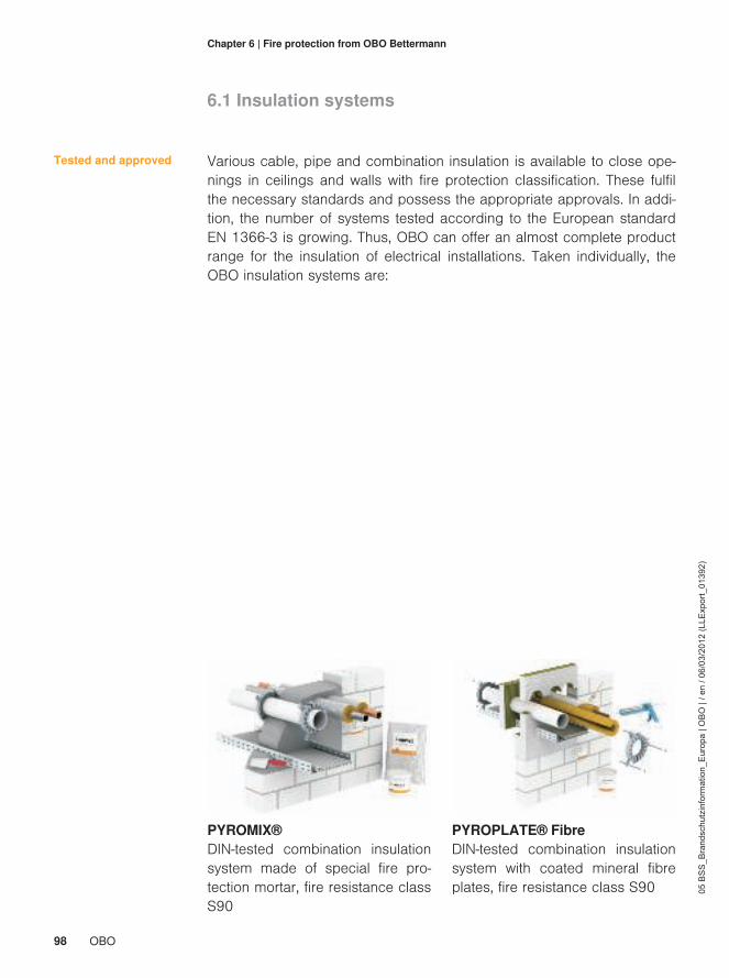
98 OBO
05 B
SS
_Bra
ndsc
hutz
info
rmat
ion_
Eur
opa
| OB
O |
/ en
/ 06/
03/2
012
(LLE
xpor
t_01
392)
Chapter 6 | Fire protection from OBO Bettermann
6.1 Insulation systems
Various cable, pipe and combination insulation is available to close ope-nings in ceilings and walls with fire protection classification. These fulfilthe necessary standards and possess the appropriate approvals. In addi-tion, the number of systems tested according to the European standardEN 1366-3 is growing. Thus, OBO can offer an almost complete productrange for the insulation of electrical installations. Taken individually, theOBO insulation systems are:
Tested and approved
PYROMIX®DIN-tested combination insulationsystem made of special fire pro-tection mortar, fire resistance classS90
PYROPLATE® FibreDIN-tested combination insulationsystem with coated mineral fibreplates, fire resistance class S90
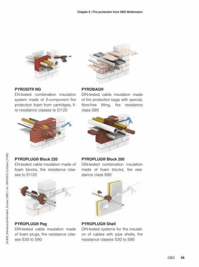
99OBO
05 B
SS
_Bra
ndsc
hutz
info
rmat
ion_
Eur
opa
| OB
O |
/ en
/ 06/
03/2
012
(LLE
xpor
t_01
392)
Chapter 6 | Fire protection from OBO Bettermann
PYROSIT® NGEN-tested combination insulationsystem made of 2-component fireprotection foam from cartridges, fi-re resistance classes to EI120
PYROBAG®DIN-tested cable insulation madeof fire protection bags with special,fibre-free filling, fire resistanceclass S90
PYROPLUG® Block 220EN-tested cable insulation made offoam blocks, fire resistance clas-ses to EI120
PYROPLUG® Block 200DIN-tested combination insulationmade of foam blocks, fire resi-stance class S90
PYROPLUG® PegDIN-tested cable insulation madeof foam plugs, fire resistance clas-ses S30 to S90
PYROPLUG® ShellDIN-tested systems for the insulati-on of cables with pipe shells, fireresistance classes S30 to S90

100 OBO
05 B
SS
_Bra
ndsc
hutz
info
rmat
ion_
Eur
opa
| OB
O |
/ en
/ 06/
03/2
012
(LLE
xpor
t_01
392)
Chapter 6 | Fire protection from OBO Bettermann
PYROCOMB® TubesDIN-tested cable insulation with pi-pe seals PYROCOMB® to insulateelectrical installation pipes, fire re-sistance class S90
PYROCOMB®DIN-tested pipe seals for insulationof combustible pipes in the PYRO-MIX®, PYROPLATE® Fibre sy-stems and as a standalone soluti-on, fire resistance class S90
PYROPLUG® MiniDIN-tested system for insulation ofcables with one-component filler,fire resistance class S90
PYROMIX® ScreedDIN-tested system for the insulati-on of cables with one-componentfiller and mineral wool, fire resi-stance class S90

101OBO
05 B
SS
_Bra
ndsc
hutz
info
rmat
ion_
Eur
opa
| OB
O |
/ en
/ 06/
03/2
012
(LLE
xpor
t_01
392)
Chapter 6 | Fire protection from OBO Bettermann
Insulation can be implemented as special solutions: • In plastic and metal line routing ducts• In underfloor systems, screed-covered or open• In cast plastic pipe shells
OBO Bettermann possesses various surveyor's reports and approvalsfrom official materials testing institutes on these subjects. In addition, therequirements of the cable system directive are fulfilled in penetration ofindividual cables with insulating materials from OBO.
For support, OBO offers calculation software to determine the materialfor insulation systems. With just a few questions, the user is guided to-wards the solution of their fire protection problem and the suitable sy-stem. The Excel-based program can be downloaded free of charge onthe website www.obo.de.
Figure: Screenshot BSSpro

102 OBO
05 B
SS
_Bra
ndsc
hutz
info
rmat
ion_
Eur
opa
| OB
O |
/ en
/ 06/
03/2
012
(LLE
xpor
t_01
392)
Chapter 6 | Fire protection from OBO Bettermann
6.2 Escape route installation systems
There are two systems within the area of escape route installations: Thesuspended ceiling systems tested by OBO for use above the suspendedfire-protection ceiling and the proven and tested fire-protection ducts ma-de from glass fibre-reinforced lightweight concrete. The situation regarding the cable coating is somewhat different, as thefunction to prevent the expansion of fire is without doubt proven, howeverthe formal certification for use in emergency exit routes cannot be issu-ed. Coordination with the construction supervisory board is always requi-red (see paragraph 6.4).

103OBO
05 B
SS
_Bra
ndsc
hutz
info
rmat
ion_
Eur
opa
| OB
O |
/ en
/ 06/
03/2
012
(LLE
xpor
t_01
392)
Chapter 6 | Fire protection from OBO Bettermann
6.2.1 False ceiling mountingOBO Bettermann has tested the following routing types according to DIN4102 Part 12 for mechanical resistance above fire protection ceilings byrecording the deformation behaviour:• Cable trays RKSM, SKS, MKS with maximum cable loads of 90 kg/m
at a support spacing of 1.5 m for a fire load of 30 minutes• Mesh cable trays GRM with maximum cable loads of up to 40 kg/m
at a support spacing of 1.5 m for a fire load of 30 minutes• Mesh cable trays G-GRM with maximum cable loads of up to 15
kg/m at a support spacing of 1.2 m for a fire load of 30 minutes• Pressure clips 2033M and 2034M for a fire load of 30 minutes• Collecting clamps 2031 M15, 2031 M30 and 2031 M70 for fire
loads of 30 and 90 minutes
Fire test reports of the Braunschweig Materials' Testing Institute and BETreports from OBO Bettermann document the resistance and deformationbehaviour of the routing variants, clearly proving the applicability of theabove systems.
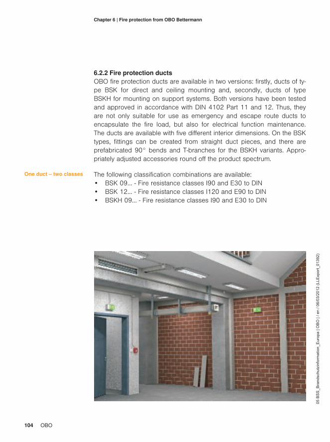
104 OBO
05 B
SS
_Bra
ndsc
hutz
info
rmat
ion_
Eur
opa
| OB
O |
/ en
/ 06/
03/2
012
(LLE
xpor
t_01
392)
Chapter 6 | Fire protection from OBO Bettermann
6.2.2 Fire protection ductsOBO fire protection ducts are available in two versions: firstly, ducts of ty-pe BSK for direct and ceiling mounting and, secondly, ducts of typeBSKH for mounting on support systems. Both versions have been testedand approved in accordance with DIN 4102 Part 11 and 12. Thus, theyare not only suitable for use as emergency and escape route ducts toencapsulate the fire load, but also for electrical function maintenance.The ducts are available with five different interior dimensions. On the BSKtypes, fittings can be created from straight duct pieces, and there areprefabricated 90° bends and T-branches for the BSKH variants. Appro-priately adjusted accessories round off the product spectrum.
The following classification combinations are available:• BSK 09… - Fire resistance classes I90 and E30 to DIN• BSK 12… - Fire resistance classes I120 and E90 to DIN• BSKH 09… - Fire resistance classes I90 and E30 to DIN
One duct – two classes
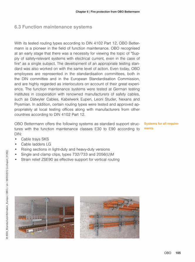
105OBO
05 B
SS
_Bra
ndsc
hutz
info
rmat
ion_
Eur
opa
| OB
O |
/ en
/ 06/
03/2
012
(LLE
xpor
t_01
392)
Chapter 6 | Fire protection from OBO Bettermann
6.3 Function maintenance systems
With its tested routing types according to DIN 4102 Part 12, OBO Better-mann is a pioneer in the field of function maintenance. OBO recognisedat an early stage that there was a necessity for viewing the topic of "Sup-ply of safety-relevant systems with electrical current, even in the case offire" as a single subject. The development of an appropriate testing stan-dard was also worked on with the same level of action. Even today, OBOemployees are represented in the standardisation committees, both inthe DIN committee and in the European Standardisation Commission,and are highly regarded as interlocutors on account of their great experi-ence. The function maintenance systems were tested at German testinginstitutes in cooperation with renowned manufacturers of safety cables,such as Dätwyler Cables, Kabelwerk Eupen, Leoni Studer, Nexans andPrysmian. In addition, certain routing types were tested and approved ap-propriately at local testing offices along with manufacturers from othercountries according to DIN 4102 Part 12.
OBO Bettermann offers the following systems as standard support struc-tures with the function maintenance classes E30 to E90 according toDIN:• Cable trays SKS• Cable ladders LG• Rising sections in light-duty and heavy-duty versions• Single and clamp clips, types 732/733 and 2056(U)M• Strain relief ZSE90 as effective support for vertical routing
Systems for all require-ments

106 OBO
05 B
SS
_Bra
ndsc
hutz
info
rmat
ion_
Eur
opa
| OB
O |
/ en
/ 06/
03/2
012
(LLE
xpor
t_01
392)
Chapter 6 | Fire protection from OBO Bettermann
The following cable-specific support structures and routing types areavailable:• Cable trays RKSM• Mesh cable trays GRM and G-GRM• Line routing ducts LKM• Cable ladders SL• Grip M collecting clamps• Pressure clips 2033M/2034M• Steel armoured pipes• Tunnel systems made of VA
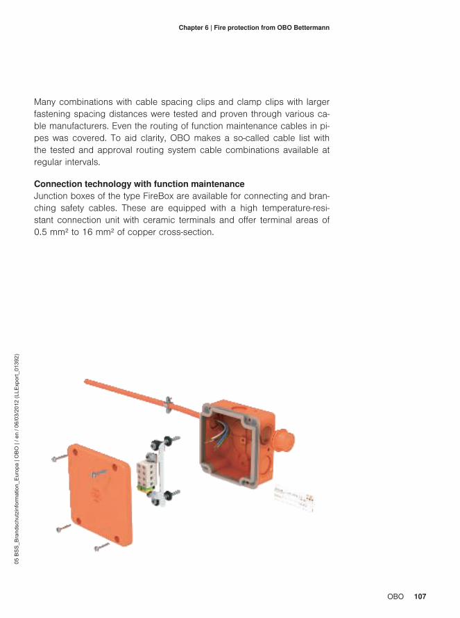
107OBO
05 B
SS
_Bra
ndsc
hutz
info
rmat
ion_
Eur
opa
| OB
O |
/ en
/ 06/
03/2
012
(LLE
xpor
t_01
392)
Chapter 6 | Fire protection from OBO Bettermann
Many combinations with cable spacing clips and clamp clips with largerfastening spacing distances were tested and proven through various ca-ble manufacturers. Even the routing of function maintenance cables in pi-pes was covered. To aid clarity, OBO makes a so-called cable list withthe tested and approval routing system cable combinations available atregular intervals.
Connection technology with function maintenanceJunction boxes of the type FireBox are available for connecting and bran-ching safety cables. These are equipped with a high temperature-resi-stant connection unit with ceramic terminals and offer terminal areas of0.5 mm² to 16 mm² of copper cross-section.

108 OBO
05 B
SS
_Bra
ndsc
hutz
info
rmat
ion_
Eur
opa
| OB
O |
/ en
/ 06/
03/2
012
(LLE
xpor
t_01
392)
Chapter 6 | Fire protection from OBO Bettermann
This large area is rounded off by the fire-tested and approved anchoringsystems. OBO offers the following fastening solutions to anchor small tovery large loads in most supportive substrates:• Metal spreading anchors for use in concrete (heavy-duty anchors,
nail ties, interior thread anchors, cavity ceiling ties)• Injection ties for use in concrete, hollow brick and porous concrete
(anchor rods inserted in plastic or metal sieve sleeves with specialmortar)
• Bolt ties for use in concrete and various types of masonry (self-tap-ping concrete screws with various head shapes)

109OBO
05 B
SS
_Bra
ndsc
hutz
info
rmat
ion_
Eur
opa
| OB
O |
/ en
/ 06/
03/2
012
(LLE
xpor
t_01
392)
Chapter 6 | Fire protection from OBO Bettermann
6.4 Industrial fire protection systems
All the above fire protection systems from OBO Bettermann are alsoused, of course, in order to fulfil construction law protection aims in indu-strial buildings and systems. The requirements for components in buil-dings of another type do not differ from the component requirements inindustrial systems.
As a complement, OBO offers cable bandages tested according to ENand IEC to prevent the spread of fires. These bandages have proventheir safe functioning using the vertical cable bundle tests and are availa-ble in two versions:• Cable bandage FSB-BS, applicable in dry interior areas, colour: inte-
rior white, exterior grey• Cable bandage FSB-WB, usable in external areas, resistant to chemi-
cals such as benzine, heating oil, butanol, hydraulic fluid, colour: inte-rior red, exterior grey
Prevention of firespread – interior and ex-terior
Industrial use of cable bandages
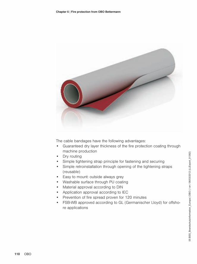
110 OBO
05 B
SS
_Bra
ndsc
hutz
info
rmat
ion_
Eur
opa
| OB
O |
/ en
/ 06/
03/2
012
(LLE
xpor
t_01
392)
Chapter 6 | Fire protection from OBO Bettermann
The cable bandages have the following advantages:• Guaranteed dry layer thickness of the fire protection coating through
machine production• Dry routing• Simple tightening strap principle for fastening and securing• Simple retroinstallation through opening of the tightening straps
(reusable)• Easy to mount: outside always grey• Washable surface through PU coating• Material approval according to DIN• Application approval according to IEC• Prevention of fire spread proven for 120 minutes• FSB-WB approved according to GL (Germanischer Lloyd) for offsho-
re applications
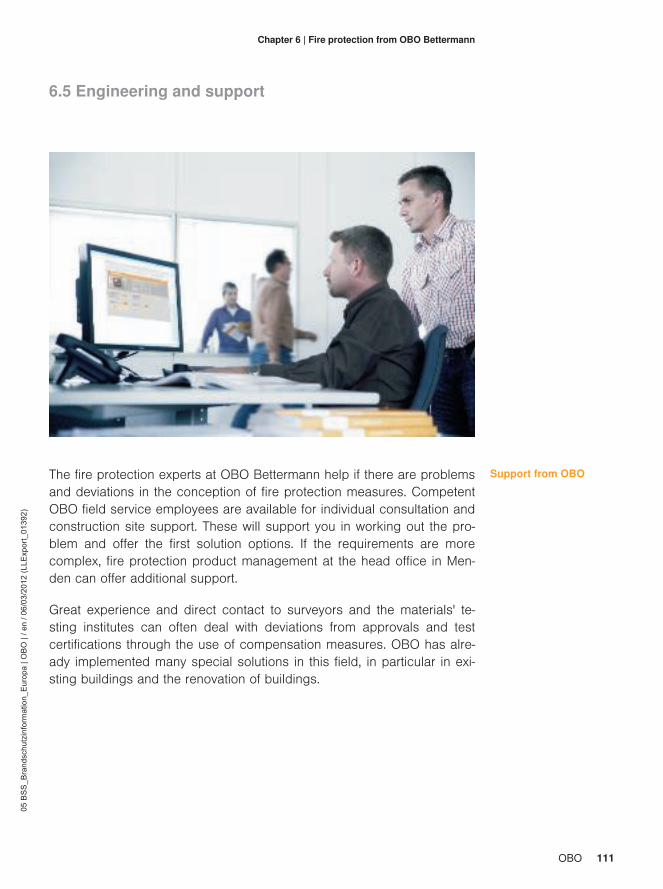
111OBO
05 B
SS
_Bra
ndsc
hutz
info
rmat
ion_
Eur
opa
| OB
O |
/ en
/ 06/
03/2
012
(LLE
xpor
t_01
392)
Chapter 6 | Fire protection from OBO Bettermann
6.5 Engineering and support
The fire protection experts at OBO Bettermann help if there are problemsand deviations in the conception of fire protection measures. CompetentOBO field service employees are available for individual consultation andconstruction site support. These will support you in working out the pro-blem and offer the first solution options. If the requirements are morecomplex, fire protection product management at the head office in Men-den can offer additional support.
Support from OBO
Great experience and direct contact to surveyors and the materials' te-sting institutes can often deal with deviations from approvals and testcertifications through the use of compensation measures. OBO has alre-ady implemented many special solutions in this field, in particular in exi-sting buildings and the renovation of buildings.
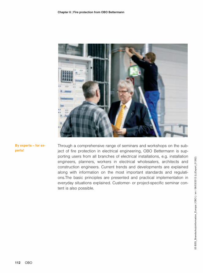
112 OBO
05 B
SS
_Bra
ndsc
hutz
info
rmat
ion_
Eur
opa
| OB
O |
/ en
/ 06/
03/2
012
(LLE
xpor
t_01
392)
Chapter 6 | Fire protection from OBO Bettermann
Through a comprehensive range of seminars and workshops on the sub-ject of fire protection in electrical engineering, OBO Bettermann is sup-porting users from all branches of electrical installations, e.g. installationengineers, planners, workers in electrical wholesalers, architects andconstruction engineers. Current trends and developments are explainedalong with information on the most important standards and regulati-ons.The basic principles are presented and practical implementation ineveryday situations explained. Customer- or project-specific seminar con-tent is also possible.
By experts – for ex-perts!

113OBO
05 B
SS
_Bra
ndsc
hutz
info
rmat
ion_
Eur
opa
| OB
O |
/ en
/ 06/
03/2
012
(LLE
xpor
t_01
392)
Chapter 6 | Fire protection from OBO Bettermann

114 OBO
05 B
SS
_Bra
ndsc
hutz
info
rmat
ion_
Eur
opa
| OB
O |
/ en
/ 06/
03/2
012
(LLE
xpor
t_01
392)
Chapter 7 | Imprint
Imprint
7.1 About the author
Stefan Ring, born in 1968, first completed training as an electronics engi-neer for energy devices. Then, he studied electrical engineering at Fach-hochschule Dortmund, with special emphases on electrical energy tech-nology, and was awarded the title of Diplom-Ingenieur (FH) in October1994. He has worked as a product manager for fire protection systemsat OBO Bettermann GmbH & Co. KG in Menden, Sauerland, since 2005.There, he manages the product portfolio of construction fire protectionfor electrical installation technology, carries out market analyses and sup-ports the marketing activities of the company with training courses, semi-nars and trade fair appearances in Germany and overseas.During his activities, he successfully completed training as a specialistplanner for construction fire protection at the European Institute for Post-graduate Education EIPOS e.V. in Dresden.Besides his work activities, Stefan Ring has been active with the volunta-ry fire brigade in his home town of Bergkamen for over 25 years, with theWeddinghofen fire engine. As the Chief Fire Officer, he is also employedas the Safety Officer. He is also a guest lecturer at the Fire Brigade Insti-tute IdF in Münster in the area of preventive fire protection.
7.2 Creation, concept, layout
Texts and photos: OBO Bettermann GmbH & Co. KG, MendenSetting and layout: Kröger Kommunikation, LünenGraphics: Keweloh Konstruktion und Design, ArnsbergExcept: Chapter 2.1 – photo of fire damage from the Brandschutz-Atlas,with the kind permission of Feuertrutz-Verlag, Cologne.

115OBO
05 B
SS
_Bra
ndsc
hutz
info
rmat
ion_
Eur
opa
| OB
O |
/ en
/ 06/
03/2
012
(LLE
xpor
t_01
392)
Chapter 7 | Imprint
7.3 Sources• [1] MBO 2002, §3 Paragraph (1) "Allgemeine Anforderungen"• [2] MBO 2002, §14 "Brandschutz"• [3] MLAR 2005• [4] EN 1366-3:2009 Fire resistance tests for service installations –
Part 3: Penetration seals• [5] ISO 834-1:1999 Fire resistance tests – Elements of building con-
struction – Part 1: General requirements• [6] EN 13501 Fire classification of construction products and buil-
ding elements – Classification using data from reaction to fire tests• [7] DIN 4102-9:1990 Fire behaviour of building materials and ele-
ments; seals for cable penetrations• [8] DIN 4102-12:1998 Fire behaviour of building materials and buil-
ding components: Circuit integrity maintenance of electric cable• [9] DIN 4102-11:1985 Fire behaviour of building materials and buil-
ding components; pipe encasements, pipe bushings, service shaftsand ducts
• [10] DIN 4102-4:1994 Fire behaviour of building materials and buil-ding components; synopsis and application of classified building ma-terials, components and special components
• [11] IEC 60332-3-22:2008 Tests on electric and optical fibre cablesunder fire conditions – Part 3-22: Test for vertical flame spread ofvertically mounted bunched wires or cables – Category A

116 OBO
05 B
SS
_Bra
ndsc
hutz
info
rmat
ion_
Eur
opa
| OB
O |
/ en
/ 06/
03/2
012
(LLE
xpor
t_01
392)
Chapter 7 | Imprint
• [12] EN 50266-2-2:2001 See [11]• [13] DIN VDE 0472-814:1991 Testing of cables, wires and flexible
cords; continuance of isolation effect under fire conditions• [14] IEC 60331-11, -12, -13 See [13]• [15] EN 50267-2, -3:1999 Common test methods for cables under fi-
re conditions – Tests on gases evolved during combustion of materi-al from cables – Part 2-1: Procedures; determination of the amountof halogen acid gas; Part 3-1: Determination of degree of acidity ofgases for cables by determination of the weighted average of pH andconductivity
• [16] IEC 60574-2 See [15]• [17] IEC 61034-1, -2:2005 Measurement of smoke density of cables
burning under defined conditions – Part 1: Test apparatus; Part 2:Test procedure and requirements
• [18] EN 61034-1, -2 See [17]• [19] EN 50266-2-4:2001 Common test methods for cables under fire
conditions – Test for vertical flame spread of vertically mounted bun-ched wires or cables – Part 2-4: Procedures; Category C
• [20] IEC 60332-3-24 Cat. C:2008 Tests on electric and optical fibrecables under fire conditions – Part 3-24: Test for vertical flamespread of vertically mounted bunched wires or cables – Category C
• [21] IEC 60332-3-22 Cat. C:2008 Tests on electric and optical fibrecables under fire conditions – Part 3-22: Test for vertical flamespread of vertically mounted bunched wires or cables – Category A


www.obo-bettermann.com
OBO Bettermann GmbH & Co. KGP.O. Box 1120 58694 Menden, Germany
Customer Service GermanyTel.: +49 (0)2373 891 500 Fax: +49 (0)2373 897 777 E-mail: [email protected]
www.obo-bettermann.com

Stand: 12/4/2012
05 BSS_Fire protection information_Europe | OBO |
LLExport_01392
Back pageRückseiteen
Wenn LAGERLISTE:Dann in Leaflet die Variabel "Lagerliste_JaNein" auf Jaund in der Variable "Lagerliste_Kundennamen" den Namen desKunden wie in CatXmedia eintragen (z.B. ELTKONTOR)
Alle Variablen:
1_Lösungskatalog_Ja_Nein .............................................................................................................................................. Ja2_Prospekt_Ja_Nein ......................................................................................................................................................... Ja3_Technische_Info_Ja_Nein......................................................................................................................................... Nein4_Katalog_JaNein ............................................................................................................................................................. Ja5_Lagerliste_JaNein...................................................................................................................................................... NeinAuszuschliessende_Attributsgruppen_ConAID...........................................................................................................24041Barcode_JaNein............................................................................................................................................................ NeinBildpreislisteJaNein ....................................................................................................................................................... NeinEAN_UFS_JaNein......................................................................................................................................................... NeinFarbiger_Produktbildhintergrund_Ja_Nein.................................................................................................................... NeinFoto_MaxHoehe..................................................................................................................................................................0InhVerz_NochLeer_JaNein ............................................................................................................................................... JaKundenNamen_Tabellenkopf .........................................................................................................................................E-nrLagerlisteFußnoteZusatztext_JaNein............................................................................................................................ NeinLagerliste_BelastungsDiagramm_JaNein ..................................................................................................................... NeinLagerliste_Kundennamen ................................................................................................................................SCHWEDENLagerlisteÜberbreite_JaNein......................................................................................................................................... NeinMassBilder_JaNein ........................................................................................................................................................... JaMassbilder_MaxHoehe......................................................................................................................................................32Masstabelle_Bestellteil_JaNein......................................................................................................................................... JaMasstabelle_Excel_JaNein ........................................................................................................................................... NeinOBO_Point_Bestseller_JaNein ..................................................................................................................................... NeinPreise_JaNein ............................................................................................................................................................... NeinProdbilder_Strich_Grafik ............................................................................................................................................. GrafikProduktbilder_MaxHoehe..................................................................................................................................................20Rabattgruppen_JaNein ................................................................................................................................................. NeinSystemLogo ..........................................................................................................................................................................Systemzubehoer_JaNein .............................................................................................................................................. NeinThinkConnBack_schwarz_weiss..............................................................................................................................schwarzThinkConnTitel_schwarz_weiss ...................................................................................................................................weissZeileWerkstoffRabattJaNein.............................................................................................................................................. JaZusAttrib_ProdText_U_Einsatzgeb_L6_Vorbelegung_721.................................................................................................0ZusText_Grau_L7_ArtNr_Ausnahmeliste_Vorbelg_0 .........................................................................................................0ZusText_GrauerHintergrund_ProdBeschrGes_Vorbelg_37..............................................................................................37ZusText_ProdukZusatzTextHinweis_L6_Vorbelegung_222 ...............................................................................................0ZusatzAttribut_L6_Wahlfrei_Vorbelegung_0.......................................................................................................................0ZusatzAttribut_L7_Wahlfrei_Vorbelegung_0.......................................................................................................................0ZusatzText_FussNote_L6_Vorbelegung_86...................................................................................................................222_LösungHintergrund_schwarz_oder_weiss .................................................................................................................weiss_PrüfzeichenJaNein .......................................................................................................................................................... Ja_QualitätszeichenJaNein................................................................................................................................................... Ja_SchnittmarkenJaNein ...................................................................................................................................................... Ja_SpezifischeProduktsymboleJaNein ................................................................................................................................. Ja
