firefly users manual - perfectflite manual.pdffirefly users manual po box 29 andover, nh 03216 url:...
TRANSCRIPT

FireFly Users Manual
PO Box 29Andover, NH 03216 URL: www.perfectflite.comVoice (603) 735-5994 Sales: [email protected] (603) 735-5221 Support: [email protected]

1
IntroductionThe FireFly Altimeter is a miniature rocket altimeter that goesbeyond just reporting how high your rocket went; it alsoreports maximum speed and with the optional Field DataDisplay can also report time to apogee, total flight time, anddescent rate. Its accuracy, ease of use, and tiny size make itideal for introductory rocket education, science fair datacollection, and contest use.
The FireFly utilizes a precision pressure sensor and 24 bitdelta sigma analog to digital converter to obtain an extremelyaccurate measurement of the air pressure surrounding yourrocket. When turned on, the altimeter “tracks” the ambientpressure surrounding your rocket to get an up-to-the-secondreading of the barometric pressure at ground level. As therocket rises, the pressure decreases, and the altimeter convertsthe pressure differential to a precise measurement of altitudeabove launch point according to the US Standard Atmospheremodel. All of the calculations are done inside the altimeter,with the results reported simply as “altitude above groundlevel”. No conversion or adjustment is necessary.
Power Button
Data Port
LED indicator
2
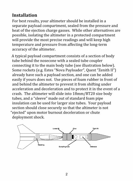
InstallationFor best results, your altimeter should be installed in aseparate payload compartment, sealed from the pressure andheat of the ejection charge gasses. While other alternatives arepossible, isolating the altimeter in a protected compartmentwill provide the most precise readings and will keep hightemperature and pressure from affecting the long-termaccuracy of the altimeter.
A typical payload compartment consists of a section of bodytube behind the nosecone with a sealed tube couplerconnecting it to the main body tube (see illustration below).Some rockets (e.g. Estes “Nova Payloader”, Quest “Zenith II”)already have such a payload section, and one can be addedeasily if yours does not. Use pieces of foam rubber in front ofand behind the altimeter to prevent it from shifting underacceleration and deceleration and to protect it in the event of acrash. The altimeter will slide into 18mm/BT20 size bodytubes, and a “sleeve” made out of standard foam pipeinsulation can be used for larger size tubes. Your payloadsection should close securely so that the altimeter is not
“ejected” upon motor burnout deceleration or chutedeployment shock.
3
Perform initial testing of your rocket without the altimeterinstalled. Make sure that the parachute is ejected and opensproperly so that you have a slow and safe landing. If youconduct your preliminary tests with the altimeter installed andthe chute doesn’t eject, the resulting high speed ballisticdescent could damage the altimeter (in addition to yourrocket!).
When installing the FireFly in larger rockets it may be easier toadd a short (~2” long) section of BT20 tube with padded endplugs for the altimeter to ride in. The short BT20 tube can beglued to the inside of the larger airframe or to a plywoodmounting plate. A static pressure sampling hole can be drilledthrough the main airframe and into the inner tube to allowexternal air pressure to get to the altimeter.
As a last resort, if accuracy isn’t of paramount importance, youcan simply tie the altimeter to the rocket’s shock cord and packit in along with the chute. If you must do this, observe thefollowing precautions:1. Use plenty of wadding between the ejection charge and the
parachute.
2. Position the parachute between the wadding and the altimeterto provide additional protection from the hot ejection chargegasses.
3. Make sure the altimeter is securely tied to the shock cord sothat it doesn’t separate and free-fall. There are two smallholes in the FireFly PCB adjacent to the power button and LEDthat can be used for this purpose.
4
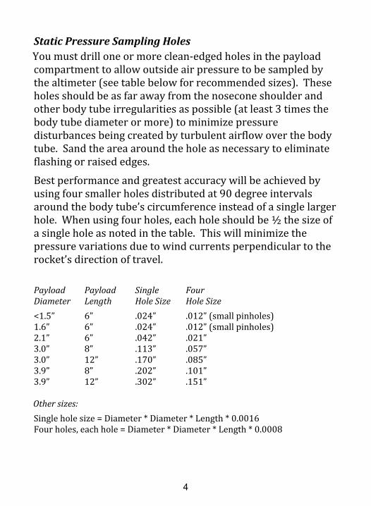
Static Pressure Sampling HolesYou must drill one or more clean-edged holes in the payloadcompartment to allow outside air pressure to be sampled bythe altimeter (see table below for recommended sizes). Theseholes should be as far away from the nosecone shoulder andother body tube irregularities as possible (at least 3 times thebody tube diameter or more) to minimize pressuredisturbances being created by turbulent airflow over the bodytube. Sand the area around the hole as necessary to eliminateflashing or raised edges.
Best performance and greatest accuracy will be achieved byusing four smaller holes distributed at 90 degree intervalsaround the body tube’s circumference instead of a single largerhole. When using four holes, each hole should be ½ the size ofa single hole as noted in the table. This will minimize thepressure variations due to wind currents perpendicular to therocket’s direction of travel.
Payload Payload Single FourDiameter Length Hole Size Hole Size<1.5” 6” .024” .012” (small pinholes)1.6” 6” .024” .012” (small pinholes)2.1” 6” .042” .021”3.0” 8” .113” .057”3.0” 12” .170” .085”3.9” 8” .202” .101”3.9” 12” .302” .151”
Other sizes:Single hole size = Diameter * Diameter * Length * 0.0016Four holes, each hole = Diameter * Diameter * Length * 0.0008
5
OperationPower SwitchThe small button on the end of the altimeter is used to turn thealtimeter on and off. The button is recessed slightly inside theedge of the circuit board to prevent accidental activation, but canbe depressed easily with a fingernail or toothpick. Pressing thebutton once will turn the altimeter ON. When the altimeter is ON,press and hold the button down until the pulsating LED goes out(about three seconds) to turn the unit OFF.
BatteryThe altimeter is powered by a standard 3 volt “CR1025” sizelithium button cell (included and installed). “Rayovac” and
“Energizer” brand are recommended for optimum fit and run time.“No Name” brands may offer significantly shorter runtime, andsome brands (e.g. Panasonic) with a large diameter negativeterminal end may not fit in the battery tray properly. “CR927”size lithium cells can also be used, but be aware that run timemay vary considerably with brand and quality of cell.
Battery life is in excess of 24 hours at normal temperatures,however operation in very cold environments (freezing orbelow) will shorten battery life. If the LED doesn’t come on whenthe power button is pressed, or when it becomes dim, it’s time toreplace the battery.
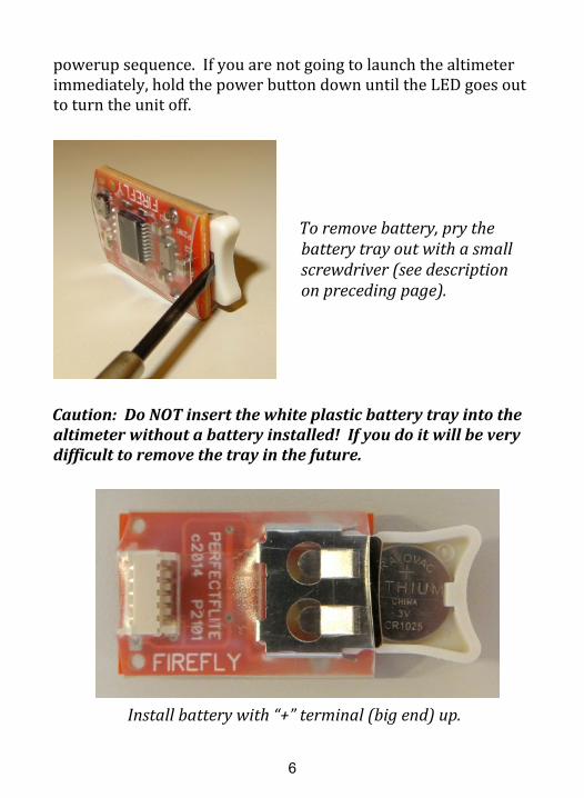
To remove the battery, insert a small screwdriver into the slot inthe white plastic battery tray (see picture on next page) and pullthe tray out of the altimeter. Push the power button to dischargeany voltage remaining in the altimeter’s circuitry. Remove theold battery from the tray and insert the new battery into the trayin the same orientation as the original. Slide the tray back intothe altimeter, and the altimeter should begin blinking the
6
powerup sequence. If you are not going to launch the altimeterimmediately, hold the power button down until the LED goes outto turn the unit off.
Caution: Do NOT insert the white plastic battery tray into thealtimeter without a battery installed! If you do it will be verydifficult to remove the tray in the future.
To remove battery, pry thebattery tray out with a smallscrewdriver (see descriptionon preceding page).
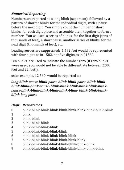
Install battery with “+” terminal (big end) up.
7
Numerical ReportingNumbers are reported as a long blink (separator), followed by apattern of shorter blinks for the individual digits, with a pausebefore the next digit. You simply count the number of shortblinks for each digit place and assemble them together to form anumber. You will see a series of blinks for the first digit (tens ofthousands of feet), a short pause, another series of blinks for thenext digit (thousands of feet), etc.
Leading zeroes are suppressed: 1,582 feet would be representedwith four digits as in 1582, not five digits as in 01582.
Ten blinks are used to indicate the number zero (if zero blinkswere used, you would not be able to differentiate between 2200feet and 22 feet!).
As an example, 12,560’ would be reported as:
long blink-pause-blink-pause-blink-blink-pause-blink-blink-blink-blink-blink-pause- blink-blink-blink-blink-blink-blink-pause-blink-blink-blink-blink-blink-blink- blink-blink-blink-blink-long pause
Digit Reported as:0 blink-blink-blink-blink-blink-blink-blink-blink-blink-blink1 blink2 blink-blink3 blink-blink-blink4 blink-blink-blink-blink5 blink-blink-blink-blink-blink6 blink-blink-blink-blink-blink-blink7 blink-blink-blink-blink-blink-blink-blink8 blink-blink-blink-blink-blink-blink-blink-blink9 blink-blink-blink-blink-blink-blink-blink-blink-blink

8
PowerupWhen the altimeter is turned on, it will report the peak altitudefrom the last flight before readying itself for flight. This iswhat you will see:
• The LED will light for one second to confirm power-on.
• A three to six digit number (range of 100 feet to 103,500feet) will be reported representing the apogee altitude ofthe last flight.Note: If power was lost during the last flight, the LED will flashslowly four times instead of reporting the apogee altitude.This error indicator will clear after the next good flight.
• There will then be a thirty second pause, giving you time toinsert the altimeter in your rocket and close up the rocket.After the thirty seconds have elapsed, the LED will blinkapproximately once per second while awaiting launch. Ifthe periodic blinking begins before you have had a chanceto insert the altimeter and close your rocket, turn thealtimeter OFF, then turn it back ON and repeat the process.If you close up your rocket while the altimeter is blinkingonce per second (awaiting launch), then the air pressurecreated when the rocket parts are pressed together couldtrigger the altimeter prematurely, resulting in erroneousdata.
Make sure you wait at least 60 seconds after turning thealtimeter ON before launching your rocket. This will ensurethat the altimeter is ready and has had time to accurately obtainthe ambient pressure at ground level.

9
After flight the altimeter will report in this sequence:• A long blink to indicate the start of the reporting sequence.• A three to six digit number representing the peak altitude
in feet.• A three second pause.• A long blink followed by a two to five digit number
representing the maximum speed during the flight in milesper hour.
• An eight second pause, and then the sequence repeats untilthe altimeter is turned OFF. The flight’s peak altitude ispreserved when power is turned off, and will be reportedevery time power is turned on until a new flight is made.
Tips for Achieving Best Accuracy• Use four static sampling ports instead of just one. Make
sure they are sized and positioned according to theinstructions presented earlier. All barometric altimetersbase their altitude measurements on the air pressuresurrounding the rocket, so getting a clean, turbulence-freesample is essential. A single hole, especially if it is over-sized, will introduce pressure fluctuations whenever therocket deviates from its normal trajectory. Four evenly-spaced holes will minimize this effect.
• With a properly designed rocket and motor combination,the parachute should eject at apogee (peak altitude), whenthe rocket is nearly stationary. This will guarantee aminimum of turbulent airflow around the rocket, and hencethe cleanest, most accurate data. If you eject yourparachute substantially before apogee, the rocket will stillbe traveling at a high rate of speed, which will degrade the

10
accuracy of any measurements due to the large fluctuationsin pressure. In addition, deploying the chute while therocket is traveling at high speed can damage your rocketdue to a zippered body tube, stripped chute, or brokenshock cord.
Ejecting at apogee is best, slightly after apogee is OK, butnever before apogee if you can avoid it. Ejecting beforeapogee will guarantee a loss in potential altitude. It willalso introduce significant degradation in altituderepeatability since the final altitude will be affected byvariations in the motor’s ejection delay.
• Use a long shock cord. This will allow the ejected payloadsection and nose cone to slow gradually rather then beingjerked to a stop when the cord comes to full extension.Again, minimizing abrupt changes in the rocket’s trajectorywill result in the smoothest, most accurate data.
TestingA simple apparatus for testing the altimeter can be made with asmall jar and a length of plastic hose. Drill a hole in the centerof the jar’s lid and insert one end of the plastic hose. Glue hosein place to achieve a tight seal (hot melt glue works well).
Turn on the altimeter and place it in the jar. Tighten the lid andwait until you can see the periodic blink from the altimeterindicating that it is ready for launch. Suck on the free end ofthe plastic hose to create a vacuum within the jar. Thealtimeter will sense this as a launch condition and the blinkingwill stop. When you stop sucking on the hose, the altimeterwill sense apogee as the pressure stabilizes. Open the hose andallow air to bleed back into the jar and the altimeter will sensedescent. The altimeter will then blink out the “altitude” thatyour vacuum was able to create within the jar.
11
Cautions• Do not touch circuit board traces or components or allow
metallic objects to touch them when the altimeter ispowered on. This could cause damage to your altimeter.
• Provide adequate padding fore and aft of the altimeter forprotection in the event of a crash or excessively hardlanding.
• Do not allow the altimeter to get wet. Only operate thealtimeter within the environmental limits listed in thespecifications section.
• Do not rupture pressure sensor diaphragm with excessivepressure or sharp object.

12
TroubleshootingAltimeter will not turn on:1. Battery is dead. Remove the battery and replace with a new
battery. See section on battery replacement earlier in manual.2. Altimeter needs reset. Remove battery, press power button, and
then re-insert battery.3. Battery does not fit properly/wrong battery. Remove the battery
and verify that it is not Panasonic brand. Confirm that smaller(negative) end of battery extends slightly through opening inbottom of battery tray.
LED comes on steady when altimeter is turned on:1. Altimeter needs reset. Remove battery, press power button, and
then insert battery.2. Internal self test failed. Contact PerfectFlite for assistance..
Battery tray was inserted without battery in place and nowit can’t be removed:Gently pull tray out until it stops (white plastic tray will catch on thetwo metal tabs on top of battery holder). Carefully insert a smalljeweler’s screwdriver or thin blade through the round opening in thebottom of the battery tray and press upward on the two metal tabs.When the tabs are free from the battery tray, the tray will slide outnormally.
13
Specifications:
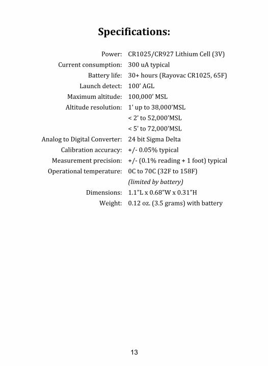
Power: CR1025/CR927 Lithium Cell (3V) Current consumption: 300 uA typical Battery life: 30+ hours (Rayovac CR1025, 65F) Launch detect: 100’ AGL Maximum altitude: 100,000’ MSL Altitude resolution: 1’ up to 38,000’MSL < 2’ to 52,000’MSL < 5’ to 72,000’MSL Analog to Digital Converter: 24 bit Sigma Delta Calibration accuracy: +/- 0.05% typical Measurement precision: +/- (0.1% reading + 1 foot) typical Operational temperature: 0C to 70C (32F to 158F)
(limited by battery) Dimensions: 1.1”L x 0.68”W x 0.31”H Weight: 0.12 oz. (3.5 grams) with battery
Warranty
All PerfectFlite products include a full three year/36 monthwarranty against defects in parts and workmanship. Shouldyour PerfectFlite product fail during this period, call or emailour Customer Service department for information aboutreturning your product. The warranty applies to the altimeteronly, and does not cover the rocket, motor, or other equipment.This warranty does not cover damage due to misuse, abuse,alteration, or operation outside of the recommended operatingconditions included with your product. Broken pressuresensor diaphragms due to puncture or exposure to ejectioncharge pressure/hot gasses are NOT covered under thiswarranty.
Liability
Due care has been employed in the design and construction ofthis product so as to minimize the dangers inherent in its use.As the installation, setup, preparation, maintenance, and use ofthis equipment is beyond the control of the manufacturer, thepurchaser and user accept sole responsibility for the safe andproper use of this product. The principals, employees, andvendors of the manufacturer shall not be held liable for anydamage or claims resulting from any application of thisproduct. If the purchaser and user are not confident in theirability to use the product in a safe manner it should bereturned to the point of purchase immediately. Any use of thisproduct signifies acceptance of the above terms by thepurchaser and user.