firesafe insulation sound reasons for acoustic...
TRANSCRIPT

Soundreasons foracousticinsulationNoise control for buildings, services and industry to meet The Building Regulations Approved Document E, 1992 Edition
F I R E S A F E I N S U L A T I O N
Ym1 (P3)CI/SfBNovember 2000 (replaces June 1999 issue)

2
How is ‘noise’ defined and how is it measured?
Noise can be generally described as unwanted sound.
Subjectively, sound is a vibration of the air that is perceived
by the human ear. Objectively, sound is a pressure
fluctuation which has an intensity (volume) and a
wavelength (pitch). The intensity of sound depends on the
pressure level, which is measured in decibels (dB) and can be
accurately quantified by a meter. Because the perception of
the human ear to sound intensity depends also on the pitch,
the decibel scale is adjusted to take account of this fact. The
adjusted scale is measured in dB(A) units and sound meters
have their scales adjusted accordingly. Pitch, or frequency, is
expressed in cycles per second. The unit of frequency is the
hertz (Hz).
The benefits of using Rockwool
Rockwool products are manufactured to a higher density
than other mineral wool slabs and provide improved
acoustic control across a wide range of frequencies.
Effective sound insulation is an essential requirement for
modern life styles. Excessive noise can increase stress,
hinder speech and can cause its own form of environmental
pollution.
Rockwool has been proven over many years to be the ideal
insulation material for all applications where noise
attenuation or noise absorption is needed - in domestic,
commercial, manufacturing, industrial and environmental
situations. In addition to its acoustic properties, its well
known thermal insulation and fire protection performance
are inherent benefits.
This sixth edition of the Rockwool Acoustic Manual gives an
explanation of the principles of acoustics pertaining to
buildings, services and industry. It also contains specific
examples of the application of Rockwool products to
constructions that will meet the requirements of the
Regulations. Where there is noise pollution, there is a
Rockwool solution.
Sound and noise
140 dBThreshold of pain
100 dBJet plane taking off at 50 metres
90 dBPneumatic drill at 3 metres
80 dBAn Intercity train from a station
platform
60 dBThe sound of a vacuum cleaner
50 dBBackground noise in an office
30 dBThe hum of a fridge
0 dB Threshold of audibility

3
Contents
Sound reasons for acoustic insulation 44
CCoonnttrrooll ooff nnooiissee lleevveellss -- TTrraannssmmiissssiioonn lloossss 55
CCoonnttrrooll ooff nnooiissee lleevveellss -- SSoouunndd aabbssoorrppttiioonn 66
CCoonnttrrooll ooff nnooiissee lleevveellss -- NNooiissyy ppllaanntt,, eeqquuiippmmeenntt,, dduuccttss aanndd sseerrvviicceess 77
Residential / commercial / other buildings
PPrroodduucctt sseelleeccttoorr 88--99
SSeeppaarraattiinngg wwaallllss 1100--1111
IInntteerrnnaall ppaarrttiittiioonnss 1122--1144
IInntteerrmmeeddiiaattee fflloooorrss 1155--1166
FFllaannkkiinngg ttrraannssmmiissssiioonn 1177
RReedduucciinngg iinntteerrnnaall nnooiissee lleevveellss 1188
RReedduucciinngg nnooiissee ffrroomm oouuttssiiddee 1199
Industrial buildings and applications
PPrroodduucctt sseelleeccttoorr 2200--2211
EEnncclloossiinngg nnooiissyy ppllaanntt aanndd mmaacchhiinneerryy 2222
WWaallll--mmoouunntteedd ccoonnttrrooll ssyysstteemmss 2233
RReedduucciinngg nnooiissee ttrraannssmmiissssiioonn ffrroomm ppiippeewwoorrkk aanndd sseerrvviicceess 2244--2255
Environmental noise
RReedduucciinngg nnooiissee aanndd vviibbrraattiioonn ffrroomm rraaiill sseerrvviicceess 2266
Alphabetical index 2277

Why do we need to insulate against noise?
Noise can be harmful to health
Exposure to high levels of noise can be dangerous in
situations requiring awareness of potential dangers. For
example when operating machinery, audible warnings may
not be heard.
Prolonged exposure to high noise levels can induce hearing
loss. It is for this reason that the Health and Safety at Work
Act requires noise levels in a work area to be limited to less
than 90 dB(A) during an 8 hour working day. At a noise level
of 105 dB(A), exposure time is limited by the Act to 15
minutes. For this reason, ear protection is a statutory
requirement in many industrial situations. Whilst the
wearing of ear defenders may be a permitted solution, in
practice they are often removed because of discomfort and
isolation from general workplace communication.
Noise can cause inefficiency at work
Even at permitted sound levels, communication is difficult
and productivity can be adversely affected. In offices,
intermittent extraneous noise can be disturbing to jobs
requiring concentration. Prolonged high pitched noise
(such as that produced by air-conditioning ducts or extract
fans) can be physically tiring and can affect personal
performance.
Low frequency noise is equally disturbing where work
requires concentration. Examples are office equipment,
generators, traffic noise and general maintenance work in
or near the workplace.
Noise can be a nuisance in the environment
Heavy traffic, low aircraft close to airports, road drills, noisy
neighbours, are types of noise frequently experienced.
Causing noise nuisance can be a legal offence. There are
statutory requirements imposing noise limits in some cases,
or standards for noise insulation to residential buildings
close to motorways and airports.
In the home, noise between rooms can be a nuisance.
Although not a statutory requirement, it is recommended
for example that internal walls between bedrooms and
toilets or bathrooms should have a minimum noise
reduction value of 38 dB.
Statutory requirements
The Building Regulations 1995, Approved Document E (1992
edition) sets standards for the noise insulation between
dwellings, which are detailed on pages 10 to 15.
Acceptable noise levels in the workplace are determined by
the Health and Safety at Work Act and the Noise at Work
Regulations 1989.
Noisy plant or machinery used in public places or close to
occupied buildings has to be insulated against noise in
accordance with current Government environmental policy
directives.
External noise
The Department of the Environment, Transport and the
Regions (DETR) requires residential buildings built in the
vicinity of an existing motorway or other major traffic route
to be shielded from noise nuisance. The current level is set
at 70 dB(A) measured at the building facade.
In a brick built elevation, this reduction is usually achieved
by the installation of double glazing. Consideration should
also be given to insulation of roof spaces with Rockwool
Rollbatt. This can be used in applications where one layer is
placed between the joists and a second layer at right angles
across the joists. This method has proved in practice to offer
an effective reduction in external noise nuisance.
New roads or railways planned close to existing residential
property are required to be provided with acoustic
shielding.
Glazing
Double or triple glazing can greatly improve sound
insulation where external noise or noise between internal
rooms is a problem. It is usual to install different
thicknesses of glass for each leaf, or to place them at a
different angle, or both, to prevent the sympathetic
vibration which occurs between two similar membranes.
The sound reduction is further improved by placing a
sound-absorbent lining in the reveals between the glazing.
Sound reasons for acoustic insulation

What measures can be taken against noise?
There are two distinct ways in which acoustic insulation can
be used to control noise; by transmission loss or by sound
absorption.
Transmission loss
Transmission loss is the reduction in the amount of sound
energy passing through a wall, floor, roof etc and is a
property of the element as a whole. It is expressed in
decibels (dB).
Noise may be due to airborne or impact sound and both
must be taken into account where appropriate.
The traditional solution for reducing sound transmission is
to use constructions with materials of high mass (eg
concrete or brickwork). However, the use of heavyweight
elements may not always be practicable. Lightweight
alternative constructions using plasterboard on studding
with a Rockwool core achieve a high level of attenuation.
Flanking transmission
In designing for acceptable levels of sound transmission,
particular attention should be paid to ways in which sound
may by-pass the element by penetrating other construction
at the periphery, or via unsealed doors or windows. Known
as ‘flanking sound transmission’, the subject is extensively
covered in Approved Document E.
Neighbourhood noise
Where manufacturing industries or certain types of leisure
and entertainments activities lie close to residential
districts, acoustic control is often desirable to help reduce
local noise nuisance. An acoustic envelope similar to that
needed for overhead or external noise may be one solution,
while some sources may need special acoustic enclosures.
In cases of neighbour noise between adjacent dwellings
causing interference, nuisance or distress, the problem can
be reduced by fitting acoustic insulation to party walls and
floor structures.
The exclusion of outside and overhead noise can be
achieved by insulating the building structure at the time of
construction, or in the case of existing buildings, as part of
a refurbishment scheme.
Incidental improvement
Where improvement schemes specify thermal upgrading
using Rockwool insulation, such installations will often
provide sufficient incidental acoustic insulation to reduce
neighbourhood noise problems.
Control of noise levels - Transmission loss
Transmission loss through wall element
(airborne sound)
Structure borne sound through floors
(impact sound)
Transmission loss through partitions
(airborne sound)
Flanking sound
transmission
Overhead noise from outside the building and
preventing neighbourhood noise nuisance
Sound absorption
Hard, smooth surfaces have the characteristic of reflecting
sound, and a noise source can become amplified in a room
lined with such materials. This process is called
reverberation, and a ‘reverberation room’ is used to test the
sound absorbency of acoustic materials.
The ability of certain materials to absorb sound, notably
Rockwool insulation, can be utilised in reducing
reverberation and reflected noise within rooms.
Sound absorption coefficient
This is the term used to describe how well (or badly) a
particular material absorbs sound energy.
It is denoted by a and is defined as:
a =Sound energy not reflected from material
Sound energy incident upon material
A perfect sound absorber would have a coefficient of a = 1,
and perfectly reflective material a coefficient of a = 0.
The absorption coefficient of materials varies with the
sound frequency (Hertz) and also with the angle at which
the sound strikes the material.
Some examples of sound absorption coefficients for
Rockwool materials are shown below.
Reducing noise levels
Where there is a need to reduce ambient noise levels within
a room, or to modify sound within a space, the answer is to
install noise absorbing linings to interior surfaces. Specialist
products, such as Rockwool Acoustic Elements and
Rockwool Sound Absorption Board are most effective for
this purpose. There is also a wide choice of ceiling linings,
for example sound absorbent panels fixed to the soffit or
suspended ceilings with lay-in boards.
In addition, bespoke systems can be developed for
individual situations with special acoustic requirements.
Absorption coefficients for Rockwool Acoustic productsMMaatteerriiaall TThhiicckknneessss ((mmmm)) MMoouunnttiinngg FFrreeqquueennccyy ((HHzz))
112255 225500 550000 11KK 22KK 44KK
Acoustic Slab 47 Direct 0.20 0.50 0.85 1.00 1.00 1.00
Acoustic Slab 67 Direct 0.30 0.70 1.00 1.00 1.00 1.00
Slab RW3 50 Direct 0.11 0.60 0.96 0.94 0.92 0.82
Slab RW3 75 Direct 0.34 0.95 1.00 0.82 0.87 0.86
Slab RW5 30 Direct 0.10 0.40 0.80 0.90 0.90 0.90
Slab RW5 30 300 mm gap 0.40 0.75 0.90 0.80 0.90 0.85
Slab RW5 75 Direct 0.40 0.75 0.90 0.80 0.90 0.85
Slab RW6 50 Direct 0.20 0.75 0.90 0.85 0.90 0.85
Slab RW6 50 300 mm gap 0.65 0.55 0.75 0.85 0.75 0.85
The absorption coefficients shown above are typical figures that can be achieved with Rockwool products.
They have been obtained from a comprehensive range of measurements made over a number of years.
Control of noise levels - Sound absorption
125 250 500 1K 2K 4K Frequency (Hz)
Abs
orpt
ion
coef
fici
ent 1.0
0.8
0.6
0.4
0.2
0
Soun
d re
duct
ion
(dB
) 12
10
8
6
4
2
0 125 250 500 1K 2K 4K Frequency (Hz)
Typical absorption coefficients -
Rockwool 67 mm Acoustic Slab
Typical noise reduction achieved through Rockwool
absorbent lining to walls and ceilings enclosing
noisy machinery

Noise transmitted along ducts
Reduction of transmitted noise through pipes and air
conditioning ductwork is achieved by the use of acoustic
linings or claddings. Products such as Rockwool Ductslab,
Ductwrap and Techwrap provide both acoustic and thermal
protection.
Room to room noise via service penetrations
Airborne and structure borne noise from adjacent rooms via
pipes, ducts and services can be reduced by the installation
of acoustic sleeves at wall penetration points. Rockwool
mineral wool slab, mat or loose fill are ideal for this
purpose.
Noise from plant and equipment
A number of practical steps can be taken to reduce noise
levels, but it is always advisable to seek expert technical
opinion before undertaking any acoustic measures.
• Whenever practicable, choose quieter machines and
processes. Ask for an assessment of plant and equipment,
bearing in mind the acoustic environment in which they
will be operating.• Surround noisy machines individually, eg heavy motors,
high speed fans, with an insulated enclosure, as in figure
1. Such enclosures can typically achieve about 30 dB
reduction. Ideally, the design should incorporate an
impervious enclosure of high mass and with an absorbent
lining to prevent reflected noise build-up within the
enclosure. Ventilation should be provided and any
openings acoustically lined.• Machines which produce vibration noise, eg ball mills,
diesel engines, centrifuges, should be positioned on
resilient isolation mounts, which may include rubber
pads and/or Rockwool slabs. The design must take into
account the loading of the machine and the vibration
frequencies.• Where there are a number of machines, treat all the
interior surfaces of the room or enclosure with noise
absorbing panels, as in figure 2. It should be borne in
mind, however, that the maximum reduction normally
achievable is 10 dB, and in cases where only the ceiling is
treated, about 5 dB.
As an alternative, quiet rooms can be constructed for
personnel, using the same techniques.• When very noisy equipment is mounted directly on an
intermediate floor, the floor itself may be subject to very
high sound pressure levels, causing noise problems in the
room below. Installing a concrete inertia base on resilient
mounts can act as an effective barrier.• Noisy pipes, ducts, and gas or liquid handling plant can
be individually sound proofed by enclosing them in dense
Rockwool. The bases of plant, such as pumps or fans
should be acoustically treated. In special cases, eg to
reduce noise levels from turbine systems in power
stations, the wrapping is made up of layers of mineral
wool and is faced with steel sheet or similar.
Control of noise levels - Noisy plant, equipment, ducts and services
Fig.2 Acoustic lining to plant room where individual
enclosure is impracticable.
Lining formed using Rockwool Acoustic Elements (see
page 23).
Fig.1 Isolation of plant noise source by individual
enclosure and acoustic treatment of base.
Enclosure formed by steel faced partition with
perforated inner sheet and incorporating Rockwool
Rigid Slab (typically RW3).
Noise transmitted along an air duct Noise transmitted via a service penetration

Commercial / residential / other buildings
Bedroom
Bedroom
Bedroom
Bedroom
Living/dining Living/dining
Bathroom Bathroom
1
3 2
5
2 3
2
33
4
6
4 22
4 4
6
6
Stairwell
6
Lobby
Selecting the right Rockwool product
The table on the facing page shows the range of specialised Rockwool acoustic products for use in
commercial, residential and other buildings. The table has been split into two parts, the first for
commercial and other buildings, the second for dwellings and other residential buildings.
The vertical columns give the location or building element, and the symbol identifies the
appropriate product and its acoustic function. Cross reference to the drawings on this page will
show specific examples of application.
OfficesOffices
High velocitypiped
services
Plant room
Lift motors
Conferenceroom
Laboratory
1
7
4
53 3
8 8
47
7
7
9
6
6
3
4
False ceiling
Access floor
6
Reference is made in much of the
following text to Rockwool Data
Sheets, eg (Data Sheet 081).
These are available from Rockwool’s
SP&A Department (01656 868420).
They describe in full detail the
performance and best acoustic
application of the product. This
Acoustic Manual may not show every
instance described in the product’s
dedicated Data Sheet.
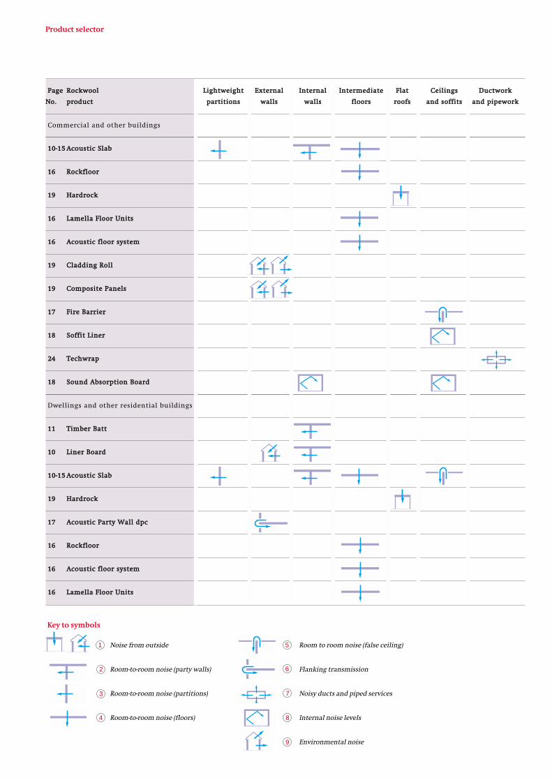
PPaaggee RRoocckkwwooooll LLiigghhttwweeiigghhtt EExxtteerrnnaall IInntteerrnnaall IInntteerrmmeeddiiaattee FFllaatt CCeeiilliinnggss DDuuccttwwoorrkk
NNoo.. pprroodduucctt ppaarrttiittiioonnss wwaallllss wwaallllss fflloooorrss rrooooffss aanndd ssooffffiittss aanndd ppiippeewwoorrkk
Commercial and other buildings
1100--1155 AAccoouussttiicc SSllaabb
1166 RRoocckkfflloooorr
1199 HHaarrddrroocckk
1166 LLaammeellllaa FFlloooorr UUnniittss
1166 AAccoouussttiicc fflloooorr ssyysstteemm
1199 CCllaaddddiinngg RRoollll
1199 CCoommppoossiittee PPaanneellss
1177 FFiirree BBaarrrriieerr
1188 SSooffffiitt LLiinneerr
2244 TTeecchhwwrraapp
1188 SSoouunndd AAbbssoorrppttiioonn BBooaarrdd
Dwellings and other residential buildings
1111 TTiimmbbeerr BBaatttt
1100 LLiinneerr BBooaarrdd
1100--1155 AAccoouussttiicc SSllaabb
1199 HHaarrddrroocckk
1177 AAccoouussttiicc PPaarrttyy WWaallll ddppcc
1166 RRoocckkfflloooorr
1166 AAccoouussttiicc fflloooorr ssyysstteemm
1166 LLaammeellllaa FFlloooorr UUnniittss
Noise from outside
Room-to-room noise (party walls)
Room-to-room noise (partitions)
Room-to-room noise (floors)
Room to room noise (false ceiling)
Flanking transmission
Noisy ducts and piped services
Internal noise levels
Environmental noise
Key to symbols
1
2
4
3
5
6
8
7
Product selector
9
Fig.3 Upgrading an existing separating wall with
access limited to one side only
Rockwool 59.5 mm Liner Board (plasterboard/mineral wool laminate) to both sides
Solid blockwork
Fig.4 Rockwool Liner Board for upgrading existing
cavity block party wall
Commercial / residential / other buildings - Separating walls
Separating walls between dwellings (new build)
The following three construction methods meet Building
Regulation requirements if carefully constructed:
Wall Type 1: Solid masonry having a large mass (weight) per
unit area.
Wall Type 2: Lightweight masonry of lower mass, but with
two leaves separated by an airspace and connected by wall-
ties only.
Wall Type 4: Lightweight framed construction (timber or
metal stud) of double wall with a wide airspace and the
minimum necessary connection between the two leaves;
usually with 2 layers of plasterboard on each face, and
Rockwool Batts or Acoustic Slab insulation within the
cavity (see Figures 5 and 6, page 11).
Indicative performance - upgraded separating wallsCCoonnssttrruuccttiioonn UUnniinnssuullaatteedd IInnssuullaatteedd wwiitthh 5599..55 mmmm LLiinneerr BBooaarrdd
SSiinnggllee--ssiiddeedd BBootthh ssiiddeess
Lightweight block (1) 50 dB (2) 55 dB (3) 58 dB (2)
cavity wall
Dense block (4) 40 dB (5) 50 dB (6) 53 dB (3)
single leaf
These values are for guidance only. It will be seen that the single leaf block construction lined on one
side does not achieve the requirements of the Building Regulations.
(1) Plasmor Stranlite (4) 200 kg/m2
(2) AIRO Report PT3223 (5) AIRO Report L/1805/1
Upgrading sound insulation of existing masonry party walls
Where a noise nuisance has been identified as being the result of poorly constructed walls
between dwellings, and statutory sound transmission values have not been achieved, or are
not considered sufficient, Rockwool Liner Board can provide the necessary acoustic
improvement. Indicative performances are given in the table below:
Upgrading existing separating wallsRockwool Acoustic Slab(Data sheet 081)Fig. 3 shows a well built solid masonry separating orparty wall with plaster on both sides, whereimprovement of sound attenuation is required, andaccess is available to only one side of the wall.
The high density of the Rockwool Acoustic Slab andthe isolation from the wall itself of the addedconstruction should give a sound reduction in theorder of 53 dB.
12.5 mm plasterboard�
67 mm Acoustic Slab
Air gap
Existing plasterboard
Existing plaster
Rockwool Liner Board (Data sheet 080)Fig. 4 shows a construction where access is availableto both sides of the separating wall. Rockwool LinerBoard is adhesive fixed to the blockwork andprovides a surface suitable for either skim coat plasteror direct decoration.

2 layers plasterboard min 30 mm overall light
metalties 67 mm
Acoustic Slab
Timber framed separating walls
Timber Batts (Data Sheet 090, Timber frame products) andAcoustic Slab (Data Sheet 081)Rockwool Timber Batts or Acoustic Slab, fixed on one side
only, in combination with two layers of plasterboard on
each side (Fig. 5) provides a sound reduction index which
meets the requirements of Approved Document E1/2/3 of
the Building Regulations.
Fig. 6 shows a similar construction but with Rockwool
Timber Batts placed between the double studs. The
constructions shown in both Fig. 5 and Fig. 6 meet the
Building Regulations requirement for sound attenuation, as
well as affording 1 hour fire resistance.
To achieve these performances, the constructions must be
carried up into the roof space.
Acoustic Party Wall dpc (Data sheet 028)Acoustic Party Wall dpc provides an acoustic cavity closer
where a separating wall joins an external cavity wall. This
meets Building Regulations and NHBC requirements.
The Acoustic Party Wall dpc is based on the Rockclose design
and is minimum 50 mm† thick, 260 mm wide insulation
bonded to 340 mm wide dpc.
†Other thicknesses can be ordered to suit different cavity widths.
Rockwool Acoustic Party Wall dpc has been assessed asgiving 1 hour fire resistance (integrity and insulation) byWarrington Fire Research Centre (Ref: C81747).
Acoustic Party Wall dpc
separating wall
Fig.7 Acoustic Party Wall dpc for sound and fire
resistance at separating walls
Fig.6 Alternative method of acoustic insulation in
timber framed separating wall using Rockwool
Timber Batts in the cavity
80 - 90 mm Timber Batt also acts as a continuousfire barrier
Fig.5 Rockwool Acoustic Slab or Timber Batts as
insulation to timber framed separating walls.
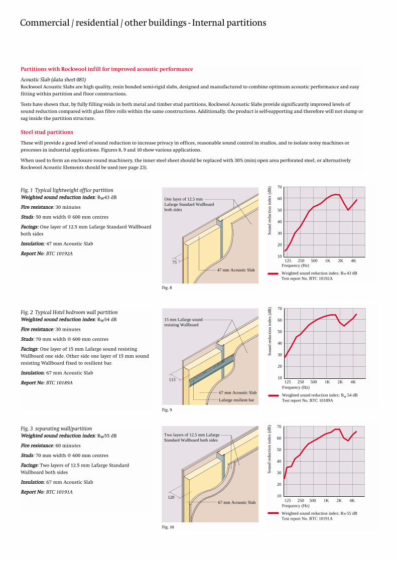
Commercial / residential / other buildings - Internal partitions
One layer of 12.5 mm Lafarge Standard Wallboard both sides
75
47 mm Acoustic Slab
125 250 500 1K 2K 4K
Soun
d re
duct
ion
inde
x (d
B)
Weighted sound reduction index: R 43 dBTest report No. BTC 10192A
70
60
50
40
30
20
10
w
Frequency (Hz)
15 mm Lafarge sound resisting Wallboard
113
67 mm Acoustic Slab
Lafarge resilient barWeighted sound reduction index: R 54 dBTest report No. BTC 10189A
125 250 500 1K 2K 4K
Soun
d re
duct
ion
inde
x (d
B) 70
60
50
40
30
20
10
w
Frequency (Hz)
Fig. 1 Typical lightweight office partitionWWeeiigghhtteedd ssoouunndd rreedduuccttiioonn iinnddeexx: Rw43 dB
FFiirree rreessiissttaannccee: 30 minutes
SSttuuddss: 50 mm width @ 600 mm centres
FFaacciinnggss: One layer of 12.5 mm Lafarge Standard Wallboard
both sides
IInnssuullaattiioonn: 47 mm Acoustic Slab
RReeppoorrtt NNoo: BTC 10192A
Fig. 2 Typical Hotel bedroom wall partition WWeeiigghhtteedd ssoouunndd rreedduuccttiioonn iinnddeexx: Rw54 dB
FFiirree rreessiissttaannccee: 30 minutes
SSttuuddss: 70 mm width @ 600 mm centres
FFaacciinnggss: One layer of 15 mm Lafarge sound resisting
Wallboard one side. Other side one layer of 15 mm sound
resisting Wallboard fixed to resilient bar.
IInnssuullaattiioonn: 67 mm Acoustic Slab
RReeppoorrtt NNoo: BTC 10189A
Fig. 8
Two layers of 12.5 mm Lafarge Standard Wallboard both sides
12067 mm Acoustic Slab
Weighted sound reduction index: R 55 dBTest report No. BTC 10191A
125 250 500 1K 2K 4K
Soun
d re
duct
ion
inde
x (d
B) 70
60
50
40
30
20
10
w
Frequency (Hz)
Fig. 3 separating wall/partitionWWeeiigghhtteedd ssoouunndd rreedduuccttiioonn iinnddeexx: Rw55 dB
FFiirree rreessiissttaannccee: 60 minutes
SSttuuddss: 70 mm width @ 600 mm centres
FFaacciinnggss: Two layers of 12.5 mm Lafarge Standard
Wallboard both sides
IInnssuullaattiioonn: 67 mm Acoustic Slab
RReeppoorrtt NNoo: BTC 10191A
Fig. 10
Partitions with Rockwool infill for improved acoustic performance
Acoustic Slab (data sheet 081)Rockwool Acoustic Slabs are high quality, resin bonded semi-rigid slabs, designed and manufactured to combine optimum acoustic performance and easy
fitting within partition and floor constructions.
Tests have shown that, by fully filling voids in both metal and timber stud partitions, Rockwool Acoustic Slabs provide significantly improved levels of
sound reduction compared with glass fibre rolls within the same constructions. Additionally, the product is self-supporting and therefore will not slump or
sag inside the partition structure.
Steel stud partitions
These will provide a good level of sound reduction to increase privacy in offices, reasonable sound control in studios, and to isolate noisy machines or
processes in industrial applications. Figures 8, 9 and 10 show various applications.
When used to form an enclosure round machinery, the inner steel sheet should be replaced with 30% (min) open area perforated steel, or alternatively
Rockwool Acoustic Elements should be used (see page 23).
Fig. 9

Partition structure SSppeecciiffiiccaattiioonn NNoommiinnaall WWeeiigghhtteedd FFiirree
tthhiicckknneessss ssoouunndd rreedduuccttiioonn RReessiissttaannccee
((mmmm)) iinnddeexx ((mmiinnuutteess))((RRwwddBB))
SSttuuddss: 70 mm width @ 600 mm centres. 95 36 30FFaacciinnggss: One layer 12.5 mm Lafarge Standard
Wallboard both sidesNNoo iinnssuullaattiioonn
As above with 67 mm Acoustic Slab 95 44 30RReeppoorrtt NNoo: BTC 10190A
SSttuuddss: 70 mm width @ 600 mm centres. 132 57 90FFaacciinnggss: Two layers of 15 mm Lafarge
sound resisting Wallboard both sidesIInnssuullaattiioonn: 67 mm Acoustic SlabRReeppoorrtt NNoo: BTC 10183A
SSttuuddss: 70 mm width @ 600 mm centres. 143 63 90FFaacciinnggss: Two layer 15 mm Lafarge
sound resisting Wallboard one side. Other
side two layers of 15 mm sound resisting
Wallboard fixed to resilient bar.IInnssuullaattiioonn: 67 mm Acoustic SlabRReeppoorrtt NNoo: BTC 10187A
SSttuuddss: 146 mm width @ 600 mm centres. 176 53 60FFaacciinnggss: One layer of 15 mm Lafarge
Firecheck Wallboard both sidesIInnssuullaattiioonn: 2 layers of 67 mm Acoustic SlabRReeppoorrtt NNoo: BTC 10193A
Fig. 11
Fig. 12
Fig. 14
Fig. 13
Sound reduction
The composition of Rockwool makes it an ideal product for sound reduction, due to its ability to absorb sound within the cavity of metal and timber
framed constructions over a wide frequency range. The table below gives examples of sound reduction figures achievable using Rockwool in a variety
of steel frame partitions.
Figures 11 to 14 show four types of metal stud construction using Rockwool Acoustic Slab, with sound reduction figures for each.
The integrity of sound reducing partition constructions can be maintained above suspended ceilings by using Rockwool Fire Barrier.
For details see page 17 (Fig. 24).

Timber stud partitions
Acoustic Slab performs effectively as an infill between timber studs.
Note: NHBC require a minimum of 38 dB for specific internal partitions.
50 x 50 mm timber studs at 600 mm centres
47 mm Acoustic Slab
75
12.5 mm plasterboard both sides Average sound reduction index: R = 39 dB
125 250 500 1K 2K 4K
Soun
d re
duct
ion
inde
x (d
B) 70
60
50
40
30
20
10 Frequency (Hz)
_
38 x 57 mm timber studs staggered at 400 mm centres
Two layers of 47 mmAcoustic Slab
130Two layers of 9.5 mm plasterboard
Weighted sound reduction index: R 59 dBAverage sound reduction index: R = 55 dBRI Test Report P7
125 250 500 1K 2K 4K
Soun
d re
duct
ion
inde
x (d
B) 70
60
50
40
30
20
10
w
Frequency (Hz)
_
Fig. 15 Lightweight domestic timber stud partitionAAvveerraaggee ssoouunndd rreedduuccttiioonn iinnddeexx: R = 39 dBFFiirree rreessiissttaannccee: 30 minutes
SSttuuddss: 50 x 50 timber studs @ 600 mm centres
FFaacciinnggss: 12.5 mm plasterboard both sides
IInnssuullaattiioonn: 47 mm Acoustic Slab
Fig. 17 Non-loadbearing separating wall constructionWWeeiigghhtteedd ssoouunndd rreedduuccttiioonn iinnddeexx: Rw59 dB
FFiirree rreessiissttaannccee: 60 minutes
SSttuuddss: 38 x 57 timber studs @ 400 mm centres
FFaacciinnggs: Two layers of 9.5 mm plasterboard both sides
IInnssuullaattiioonn: Two layers of 47 mm Acoustic Slab
RReeppoorrtt NNoo: RI Test Report P7
Fig. 16 Typical lightweight office partition adjacent tofactoryWWeeiigghhtteedd ssoouunndd rreedduuccttiioonn iinnddeexx: Rw46 dB
FFiirree rreessiissttaannccee: 60 minutes
SSttuuddss: 44 x 75 timber studs @ 600 mm centres
FFaacciinnggs: Two layers of 12.5 mm Lafarge Standard
Wallboard both sides
IInnssuullaattiioonn: 67 mm Acoustic Slab
RReeppoorrtt NNoo: L/1944/A/7
Fig. 15
Fig. 17
44 x 75 mm timber studs at 600 mm centres
67 mm Acoustic Slab
125
Two layers of 12.5 mm Lafarge Standard Wallboard
Fig. 16
Weighted sound reduction index: R 46 dBTest Report L/1944/A/7
125 250 500 1K 2K 4K
Soun
d re
duct
ion
inde
x (d
B) 70
60
50
40
30
20
10
w
Frequency (Hz)
Commercial / residential / other buildings - Internal partitions

Commercial / residential / other buildings - Intermediate floors
The National Building Regulations
Floors, walls and partitions within single-occupancy dwellings
Regulations cover only walls and floors separating
dwellings from other buildings or separate dwellings
within the same building. There are no requirements for
walls or floors within individual dwellings.
It is, however, important that architects and designers
should provide a degree of acoustic insulation in these
situations. Bathrooms and WCs for instance, should not be a
source of annoyance to people in adjoining bedrooms. (See
notes on page 4).
Floors
The Approved Document E/1/2/3 of the Building Regulations
sets minimum sound insulation standards for floors tested
in accordance with BS 2750 and BS 5821.
The standards apply to both airborne and impact sound,
and separate criteria are set for new-build and conversion
applications, as follows:
Airborne sound Impact soundWeighted standardised Weighted standardised
level difference (DnT,w) pressure level(L’ nT,w)Conversion
48 dB 65 dB
New-build
52 dB 61 dB
To achieve the required noise transmission losses in terms
of both airborne and structure-borne sound a variety of
constructions can be considered, of which the following are
the more common:
Floor Type 1: Solid concrete of a specified minimum
mass/unit area with a resilient floor covering (to reduce
impact noise)
Floor Type 2: Solid concrete of lower mass, with a
separating, sound-deadening layer between the structural
floor and the floor finish (usually screed). Edge insulation,
in the form of Rockwool Isolation Strip is also required to
prevent flanking transmissions of structure-borne sound
via adjacent walls.
(Floating floor construction)
Floor Type 3A: Timber (or steel) joisted floors, with two
layers of plasterboard on the soffit, plus a sound absorbing
element between the joists (Rockwool Timber Roll or
Rollbatt) and a resilient layer (Rockwool Rockfloor) between
subfloor and floor finish.
NOTE: It is strongly recommended that Floor Types 3B and
3C (Ribbed floors) shown in Part E of the Building
Regulations are not used.
Upgrading existing floor constructions
In conversions of buildings for multiple occupancy
residential use, Rockwool mineral wool rolls, slabs or batts,
in conjunction with additional floor and ceiling layers, can
be used to upgrade the sound insulation to acceptable
levels.
Such a construction is shown in figure 18.
2 layers 47 mm Acoustic Slabfitted between joists
hardboard layer over square edgedfloorboards
double layer of 12.5 mm plasterboard
Fig.18 Upgrading the airborne sound insulation of a
fixed timber floor using 2 layers of 47 mm Rockwool
Acoustic Slab.
Approximate sound reduction: 43 dB.
Note that this treatment will slightly improve the
impact noise resistance.

Floating floor constructions - timber joisted and concrete
Commercial / residential / other buildings - Intermediate floors
Fig.19 Timber joisted floor using RockwoolRockfloor and Rockwool Rollbatt
Airborne sound reduction: Rw56 dB
Impact sound reduction: Ln,w62 dB
Laboratory test report L 2206/E* shows that thisconstruction meets the requirements of the BuildingRegulations for separating floors between dwellings.
18 mm chipboard on19 mm plasterboard plank on 30 mm Rockfloor on dpm
Rockwool Isolation Strip
19 + 12 mm plasterboard ceiling
100 mm Rollbatt between joists
15 mm plywood on timber joists
Rockwool Acoustic Floor
RW2 100 mm (see data sheet 072)
22 mm timber floorboards
31.5 mm plasterboard ceiling
Fig.22 Timber joisted floor using RockwoolAcoustic Floor System
Airborne sound reduction: Rw53 dB
Impact sound reduction: Ln,w62 dB
Laboratory test report AIRO No. L/2388/3. *Theconstruction consists of panels manufactured from 25 mm Rockwool bonded to 20 mm tongued andgrooved, special high density cement particle board,together with 100 mm RW2 between joists. Tests showthat this construction meets the requirements of theNational Building Regulations and TechnicalStandards for conversion applications.
Note
*In order to protect the chipboard from moisture
migrating from a damp structural floor, it is
recommended that a dpm (e.g. polyethylene) is placed
below and lapped up and over the perimeter of the
insulation.
Fig.20 Beam and block floor using RockwoolRockfloor on levelling screed
Airborne sound reduction: DnT,w52 dB
Impact sound reduction: L,nT,w 54 dB
Site test report AAD 91137* shows that this
construction meets the requirements of the Building
Regulations for separating floors between dwellings.
levelling screed on beamand block floor (277 kg/m2)
18 mm chipboard on 30 mm Rockfloor on dpm
battened ceiling
Rockwool Isolation Strip
20 mm screed
9.5 mm plasterboard
65 (min) screed on 30 mm Rockfloor
Rockwool Isolation Strip
dense concrete floor slab (min 300 kg/m2)
Fig.23 Dense concrete floor using RockwoolRockfloor under screed
Airborne sound reduction: DnT,w 52 dB
Impact sound reduction: L,nT,w 53 dB
Laboratory test report L 2206/B modified by
Assessment letter 9th July 1993 shows that this
construction meets the requirements of the Building
Regulations for separating floors between dwellings.
Fig.23a Screeded beam and block floor
Airborne sound reduction: Rw 59 dB
Impact sound reduction: LnT,w 44 dB
Laboratory test report L 2206/B shows that this
construction meets the requirements of the Building
Regulations for separating floors between dwellings.
Fig.21 Beam and block floor using RockwoolLamella Floor Units
Airborne sound reduction: Rw60 dB
Impact sound reduction: Ln,w45 dB
Laboratory test report L 2206/A* shows that this
construction meets the requirements of the Building
Regulations for separating floors between dwellings.
Note: In-situ concrete or concrete plank floors can be
substituted for the beam and block floors shown in
Fig. 21 provided the overall weight is 300 kg/m2
minimum. If such a construction does not include a
battened ceiling, reference should be made to
Assessment Letter dated 9th July 1993 in addition to
the relevant test report.
48 mm Lamella Floor Units on dpm
Rockwool Isolation Strip
levelling screed on beam and block floor (300 kg/m2)
battened ceiling
12.5 mm plasterboard
35 mm levelling screed
battened ceiling with50 mm RW2 between battens
edge insulation with offcuts
12.5 mm plasterboard
35 mm levelling screedon beam and blockfloor (min 300g/m )2
65 (min) screed on30 mm Rockfloor

Commercial / residential / other buildings - Flanking transmission
1. Rockwool Fire Barrier hung from soffit or beam and draped over the partition head (See Fig. 22)
IImmpprroovveemmeenntt TToottaall rreedduuccttiioonn
50 mm Fire Barrier +12 dB 42 dB
100 mm Fire Barrier (2 x 50 mm) +16 dB 46 dB
50 mm Fire Barrier foil faced +14 dB 44 dB
100 mm (2 x 50 mm) Fire Barrier foil faced +20 dB 50 dB
2. Both ceilings overlaid with lightweight insulation
47 mm Rockwool Acoustic Slab +7 dB 37 dB
67 mm Rockwool Acoustic Slab or 100 mm Rollbatts +10 dB 40 dB
75 mm Rockwool RWA45 +12 dB 42 dB
100 mm Rockwool RWA45 or 150 mm Rollbatts +16 dB 46 dB
120 mm Rockwool RWA45 or 100+80 mm Rollbatts +18 dB 48 dB
N.B. Overlaying ceiling tiles with an insulating product might impair the fire resistance of the tiles.
The ceiling manufacturer should be consulted if this method is used.
Improving room-to-room sound attenuation aboveinternal partitions
The integrity of sound reducing partition constructions can
be maintained above suspended ceilings by the use of
Rockwool insulation products.
There are two methods. The first involves filling the void
between the soffit and the head of the partition with a
dense insulation. The other method is to totally overlay both
ceilings either side of the partition with a lightweight
insulation.
The figures quoted below are based on test results obtained
using a typical suspended ceiling lay-in grid tile system
providing a basic 30 dB room-to-room sound attenuation:
Rockwool FireBarrier
Buildex HT rangefixings or M6 coachscrews at max300 mmcentresFBS
punchedstrap
headplate
ceiling board
Fig.24 Fire Barrier above partition
Acoustic Party Wall dpc
separating wall
Fig.25 Acoustic Party Wall dpc
Fire Stop
Fire Stop
Fire Stop
Fire Stop
Fire Stop
Fire Stop
Fire Stop
Fire Stop
Fire Stop
Fire Stop
Fig.26 Access Floor FireStop Slab (typically directly
under partition line)
Rockwool Acoustic Party Wall dpc (data sheet 028)The use of this product as illustrated in Fig. 25 will avoid the
flanking transmission commonly associated with
lightweight inner leaves of blockwork. It will also afford the
requisite fire resistance as defined in the Building
Regulations.
Rockwool Access Floor FireStop Slab (data sheet 061)Access Floor FireStop Slab, used primarily for firestopping
purposes, has the added advantage of reducing unwanted
flanking transmission via the access floor void. The product
is illustrated in Fig. 26 and is cut on site to suit access floor
void depth.
Rockwool Fire Barrier (data sheet 060)A single layer of Fire Barrier will improve the room-to-room
performance of the ceiling by approx. 12 dB, and by up to
20 dB when a double layer is used with foil facing. (see Fig.
24 below).

Commercial / residential / other buildings - Reducing internal noise levels
cover strips
timber battens
wall
air space
RockwoolAcoustic Matnom. 50 mmthickness
0 125 250 500 1K 2K 4KFrequency (Hz)
Rating according to EN ISO 11654: 1997Weighted Sound Absorption Coefficient ∝ = 0.85Test report BTC 10268A
1.2
1.0
0.8
0.6
0.4
0.2
abso
rptio
n co
effi
cien
t
w
Acoustic control
Rockwool Sound Absorption BoardThe product consists of rigid, resin bonded insulation, faced
on one side with black glass tissue. The structure of Sound
Absorption Board makes it an ideal product for use as a
sound absorber with characteristically high coefficients
over a wide range of frequencies.
The product is designed for use behind perforated/slatted
linings in areas such as cinemas, theatres, leisure centres,
auditoria and other locations where high levels of acoustic
control are required (See Fig. 27). The product can also be
used for noise reduction requirements in plant room areas.
Rockwool Sound Absorption Boards are manufactured to
standard dimensions of 1200 x 600 x 50 mm and
1200 x 600 x 70 mm.Fig.27 Rockwool Sound Absorption Board behind
a slatted hardwood facing for acoustic control in
an auditorium.
Fig.28 Rockwool Acoustic Mat showing fixing
method
Rockwool Acoustic MatRockwool Acoustic Mat is a flexible liner which offers a
simple technique for sound absorption in temporary or
permanent situations. It is ideal for both commercial and
industrial use, and is typically manufactured to a standard
width of 1200 mm and nominal thickness of 50 mm.
Acoustic Mat consists of a Rockwool core totally enclosed in
a fire retardant fabric, which is stitched at intervals to form
a quilt. It can be used in either vertical or horizontal
applications.
Typically, Acoustic Mat is fixed as indicated in Fig. 28. The
product can be used in recording or broadcasting studios
and auditoria for effective sound control. It can also be used
for sound absorption requirements in industrial
environments.
Absorption coefficients are shown below the diagram.
Soffit Lining Solutions (Data sheet 201)Two products, High Impact Liner Board and Soffit Liner
provide both effective acoustic and thermal insulation for
concrete soffits.
High Impact Liner Board is a laminate of high density
Rockwool Lamella Slabs bonded with an adhesive to cement
bonded particle board. High Impact Liner Board provides a
cost effective means of achieving excellent levels of thermal
insulation coupled with fire safety and acoustic insulation.
The boards offer excellent impact resistance and will
significantly reduce the risk of condensation (Fig. 29).
Soffit Liners are robust Rockwool Slabs with a high quality,
Class ‘O’ decorative finish particularly suited for
underground vehicle parks and other situations requiring
significant thermal insulation and acoustic absorption
(Fig. 30).
Fig.29 High Impact Liner Board Fig.30 Soffit Liner

Rockwool Hardrock Roofing Boards (data sheet 050)A commercial flat roof incorporating
150 mm Rockwool Hardrock with a single ply waterproof
membrane has been shown to achieve a sound reduction
index of 44 dB (SRL Ltd test report No. C/6487/405/1). This
construction is particularly suitable for buildings close to
airports (see Fig. 31).
Alternatively, 80 mm Hardrock in a similar roof
construction will achieve a weighted sound reduction index
of 38 dB (University of Salford test reference No. 90/4/18).
Rockwool Cladding Roll (data sheet 011)Rockwool Cladding Roll U/F or Cladding Roll Alu-faced, used
as the thermal insulant between profiled steel sidewall
cladding and steel sheet liner panels, provides a good sound
insulation barrier. An weighted sound reduction index of
Rw37 dB can be expected (see Fig. 32 ).
single ply membrane
150 mm total thickness HardrockStandard Roofing Board
65 mm deepprofiled aluminiumKorrugal deck
Fig.31 Flat roof detail, Stansted Airport, with
Rockwool Hardrock Roofing Board - Sound
reduction index = 44 dB.
Commercial / residential / other buildings - Reducing noise from outside
Rockwool-CORED composite acoustic panelsComposite Acoustic Panels consist of sheet steel faces,
bonded to a Rockwool core. The constructions shown below
(Figs. 33 and 34) achieve an average
32 dB sound attenuation within the range 125 Hz to 4000
Hz. The panels can be profiled to interlock at the edges. For
further information on panel systems, please contact
Rockwool Ltd., Systems Division.
foam seal
85 mm Rockwool core
sheet steel
sheet steel
Fig.33 Support detail
Fig.34 Edge profile
125 250 500 1K 2K 4K Frequency (Hz)
80
70
60
50
40
30
20
10
0
sou
nd r
educ
tion
inde
x (d
B)
With Rockwool -Weighted sound reduction index: R 32 dBTest report No. AC97-216 Test No.1
w
50 x 50 x 1.6 mmsteel rails
85 mm Rockwoolsheetsteel
foam seals
Fig.32 Sidewall cladding with Rockwool Cladding
Roll and Rock-Lam Thermal Break strips
- Weighted sound reduction index = Rw37 dB
The prestigious telecommunications centre for Orange at
Darlington required a high performance acoustic roofing
system. Aesthetically it also demanded a system which did
not involve mechanical fixings penetrating the
undersurface of the ‘on view’ roofing deck.
The solution was an acoustic flat roofing system
comprising a perforated steel deck overlaid with a non-
woven glass fleece barrier, above which the insulation
build-up includes 60 mm Hardrock covered with a
bituminous vapour control layer and a further 70 mm of
Hardrock Single-Ply Adhered boards.
The roofing system is considered environmentally friendly,
has excellent thermal and fire protection capabilities as
well as outstanding dimensional stability.

Industrial buildings
Selecting the right Rockwool product
The table on the facing page shows the range of specialised Rockwool acoustic products for
use in industrial buildings, and in particular, for the acoustic insulation of services, plant
and machinery.
The vertical columns give the location or building element, and the symbol identifies the
appropriate product and its acoustic function. Cross reference to the drawing will show
specific areas of application.
Environmental noise
Noise from outside
Noisy plant and machinery
Internal noise levels
Noisy ducts and piped services
Room-to-room noise (partitions)
Room-to-room noise (ceilings)
WorkshopsOffice
1
Noisy plantWorkshops
2
6
2
3
2
1
4
1
2
3
4
5
6
Key to symbols
7
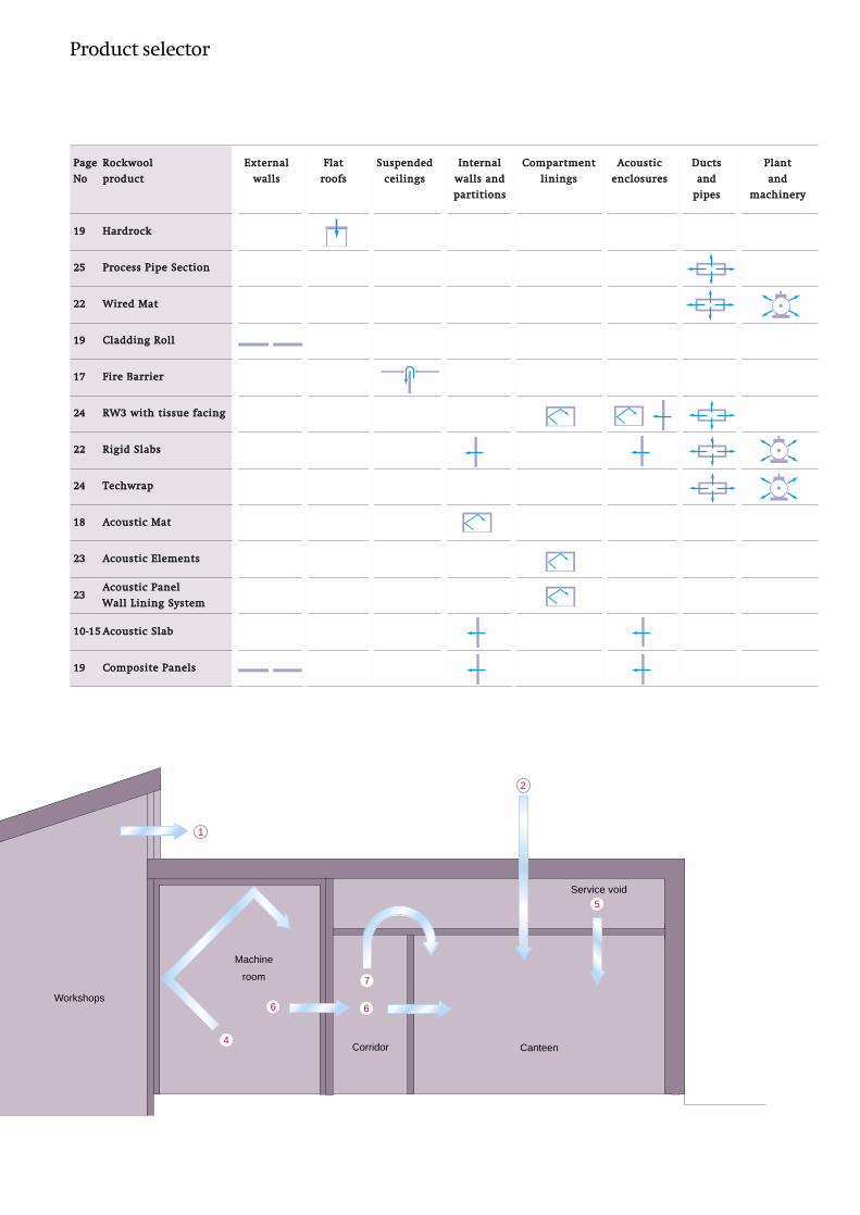
PPaaggee RRoocckkwwooooll EExxtteerrnnaall FFllaatt SSuussppeennddeedd IInntteerrnnaall CCoommppaarrttmmeenntt AAccoouussttiicc DDuuccttss PPllaanntt
NNoo pprroodduucctt wwaallllss rrooooffss cceeiilliinnggss wwaallllss aanndd lliinniinnggss eenncclloossuurreess aanndd aanndd
ppaarrttiittiioonnss ppiippeess mmaacchhiinneerryy
1199 HHaarrddrroocckk
2255 PPrroocceessss PPiippee SSeeccttiioonn
2222 WWiirreedd MMaatt
1199 CCllaaddddiinngg RRoollll
1177 FFiirree BBaarrrriieerr
2244 RRWW33 wwiitthh ttiissssuuee ffaacciinngg
2222 RRiiggiidd SSllaabbss
2244 TTeecchhwwrraapp
1188 AAccoouussttiicc MMaatt
2233 AAccoouussttiicc EElleemmeennttss
2233AAccoouussttiicc PPaanneell
1100--1155 AAccoouussttiicc SSllaabb
1199 CCoommppoossiittee PPaanneellss
Machine
room
Corridor Canteen
2
2
Workshops
4
6 6
5
1
7
Service void
WWaallll LLiinniinngg SSyysstteemm
Product selector

Industrial processes
Many industrial processes are inherently
noisy and require acoustic treatment to
reduce noise to acceptable levels. To protect
personnel from prolonged exposure to high
levels of noise, which can induce hearing
loss, the The Health and Safety at Work Act
(1974) and Noise at Work Regulations (1989)
stipulate a “first action level” of 85 dB(A)
daily personal noise exposure normalised to
an eight hour working day. HSE guidance on
the Noise at Work Regulations states that
there is a quantifiable risk of hearing
damage from exposure between 85 dB(A)
(first action level) and 90 dB(A) (second action
level), and a residual though small risk below
85 dB(A).
To achieve reduced noise levels, a number of
steps can be taken:
1. Use quieter machines and processes
2. Enclose noisy machines individually
3. Where there are a large number of
machines, treat the whole interior surface
with noise absorbing panels.
(The maximum practicable reduction in
environmental noise within plant rooms is
10 dB. A typical reduction in a room where
only the ceiling is treated is 5 dB).
4. Apply acoustic control methods to noisy
pipes, ducts and air-handling plant.
Noisy equipment
Industrial and HD Wired Mats (data sheet 120)
Rockwool Industrial and HD Wired Mats are ideally suited
for use where acoustic or thermal insulation of large or
irregularly shaped equipment is required.
Alternatively, where a higher degree of acoustic
performance is required, or where access to machinery
cannot be restricted, an enclosure may be installed around
the equipment or the whole compartment may be treated.
The figures below show the two alternatives
diagrammatically.
Fig.36 Acoustic lining to plant room where individual
enclosure is impracticable.
Lining formed using Rockwool Acoustic Elements (see
page 23)
Ventilation should be provided and any openings
acoustically lined.
Fig.35 Isolation of plant noise source by acoustic
treatment of base and individual enclosure.
Enclosure formed by steel faced partition with
perforated inner sheet and incorporating Rockwool
Rigid Slab (typically RW3).
Industrial buildings - Enclosing noisy plant or machinery
Rockwool Rigid Slabs (data sheet 030)Rigid Slabs are part of a range of rigid, semi-rigid and
flexible slabs which, depending on type, can be used at
temperatures of up to 800oC without any functional
deterioration. They are manufactured in a variety of
thicknesses and densities to suit most requirements.
The range of densities allows the designer to select the
product with the correct compression strength and elastic
limit properties for its structural use in the sound
insulation of plant and machinery.

Rockwool Acoustic Element, standard size, fixed
over a 50 mm cavity.
Test method: ISO 354 (1985)
Rockwool Acoustic Panel Wall Lining SystemThe system provides a simple technique for the wall
application of a sound absorbent lining protected by a
perforated metal facing. The unique construction results in
a panel with optimum acoustic absorption with the
advantage of high impact resistance.
The system consists of lengths of retaining channel which
are fixed at 1200 mm centres into which the absorber panels
are held by cover strips, secured by self tapping screws.
The metal facing of the panel forms a tray into which a
specially constructed Rockwool core is laminated.
No vertical supports are required other than the use of the
same retaining channels at external corners or vertical
terminations of the system.
The product has been tested, with a 50 mm air gap, for
random incidence sound absorption to BS 3638: 1987 and
the test results, shown in the graph, give the measured
absorption coefficients over a range of frequencies taken at
1/3 octave intervals.
Rockwool Acoustic Panel Wall Lining System can also be
fixed direct to a wall.
For further details please contact the Industrial Technical
Services Department.
Fig.38 Rockwool Acoustic Panel Wall Lining System
on 50 mm battens.
Industrial buildings - Wall-mounted acoustic control of noisy plant and machinery
Rockwool Acoustic ElementsRockwool Acoustic Elements provide exceptional levels of
acoustic absorption - at certain octave bands the absorption
coefficient can be 1.0 (measured in accordance with
ISO 354).
Particularly suitable for use in work areas subject to intense
noise levels from plant and machinery, Rockwool Acoustic
Elements are available in a range of sizes and are simply
bolted to bulkhead and soffit areas. The perforated steel and
'impervious film' facing allows easy washdown and
maintenance and provides high resistance to impact
damage - especially important features in plant rooms.
Standard dimensionsThickness: 50 mm
Outside dimensions: 600 x 1200 mm (nom.). The Elements
can be easily cut to size on site and positioned to avoid
services and penetrations.
Other sizes may be available to special order.
impervious film facing
Rockwool
perforated steel
0 125 250 500 1K 2K 4KFrequency (Hz)
Abs
orpt
ion
coef
fici
ent
1.0
0.8
0.6
0.4
0.2
galv. m.s. retaining channels
Rock-Lam core
perforated metal facing600 x 1200 mm
0 125 250 500 1K 2K 4KFrequency (Hz)
Abs
orpt
ion
coef
fici
ent 1.0
0.8
0.6
0.4
0.2
Fig.37 Rockwool Acoustic Element
Casing: Single piece, aluminium, galvanised or
stainless steel sheet formed into open-backed
'cassette'. Front face perforated with 3 mm dia
holes, 33% open area.
Inlay: Rockwool with plastics wrapping.
Note: Elements also available in 50 and 100 mm
thicknesses and in outside dimensions to suit.
Rockwool Acoustic Acoustic Panel Wall Lining
System on 50 mm battens - Average noise
absorption coefficient: 0.90.

Industrial buildings - Reducing noise transmission from pipework and services
drop rodbearer
duct wall
TECHWRAP AROUND PIPE
TECHWRAP AROUND DUCT
polymerichigh-massfacing
Rockwool Techwrap
Fig.40 High level acoustic attenuation provided to
ducts, pipes and enclosures - Rockwool Techwrap
dB IMPROVEMENTS DOUBLE LAYER TECHWRAP SINGLE LAYER
50
40
30
20
10
0
dB s
ound
red
ucti
on
Frequency (Hz)
50 63 80 100 125 160 200 250 315 400 500 630 800 1K 1.25K 1.6K 2K 2.5K 3.15K 4K 5K
Rockwool Techwrap (data sheet 131)Techwrap is a ‘high mass’ faced Rockwool mineral wool
comprising:
• Reinforced aluminium foil (inner)• Rockwool, 25 mm standard (other thicknesses available
to special order)• High mass polymeric, 5 kg/m2 standard (10 and 15 kg/m2
also available to special order)• Woven glass cloth• Reinforced aluminium foil (outer)
Sound reduction testNoise level improvements (in dB) through a tested 0.8 mm
duct are given in the graph below for both single and double
layers of standard 25 mm Rockwool Techwrap.
duct clamps
resilient pads
anti-vibration mat
metalduct
Rockwool RW3 with applied tissue lining.The perimeter of the tissue facing is returned behind the edges of the slab to help prevent delamination of the facing in turbulent or high velocity airstreams
Fig.39 Internal acoustic lining to attenuate duct-borne noise - Rockwool RW3 and tissue lining on the
exposed side
Air conditioning and ventilation ductwork
Rockwool RW3 with tissue liningRW3 with a tissue lining applied to the exposed surface can
be used as an internal lining to ducts (see Fig. 39). The
perimeter of the tissue facing is returned behind the edges
of the slab to help prevent delamination of the facing in
turbulent or high velocity airstreams. The acoustic lining
attenuates noise levels both within the duct and outside.
Noise transmitted along an air duct

Rockwool Process Pipe Sections and Rockwool Wired Mats (data sheets 101 and 120) These products can be used to significantly reduce noise
emissions from pipes.
For optimum acoustic performance, the following
principles should be followed.
• Process Pipe Section or Wired Mat to be installed tightly
around the pipe• Where suitable, Wired Mat to be used in preference to
Pipe Section• An outer cladding to be applied to the Rockwool
insulation• Cladding weight to be as great as practicable• Rigid mechanical contact between pipe and outer
cladding to be diligently avoided
Although the sound reduction resulting from use of
Rockwool pipe insulation is significantly affected by the size
of the pipe treated, the example shows a typical level of
performance.
It should be noted that the sound attenuation obtained at
low frequencies will be less for smaller diameter pipes. In
some cases, a negative insertion loss may occur at
frequencies below 250 Hz.
Note: An extensive range of Rockwool Offshore products is
also available to provide thermal and acoustic insulation to
plant. Please contact the Rockwool Industrial Division for
further details.
Fig.41 Reduction of structure borne noise at duct
penetration - Rockwool Industrial Handfill / RW6 Slab
Fig.42 Penetration of structure by insulated pipework
- RockLap 800 H & V Pipe Sections
Fig.43 Alternative method with pipe sleeved through
wall - using low density Rockwool packed tightly
Fig.44 100 mm Wired Mat + 0.75 mm steel cladding without support
rings. Pipe diameter 308 mm. The sound reduction achieved is shown
in the graph below.
sheet metal cover
tie wires
0 125 250 500 1K 2K 4KFrequency (Hz)
Soun
d re
duct
ion
(dB
)
50
40
30
20
10
Services penetrations
Figures 41 to 43 below show various techniques, using
Rockwool materials, for dealing with noise transmission
through a wall (or floor) caused by the penetration of ducts,
pipes or other services.
separatingwall
Rockwool packing(Industrial Handfill)
Rockwool RW6 slab
loose flanges bedded in mastic
insulation continuousthrough wall and slightly compressed
dense sand/cement fill
dense sand/cement fill
steel pipesleeve
Rockwool packed tightly
Pipework
Noise transmitted via a service penetrationSound reduction graph for construction shown in
Figure 44
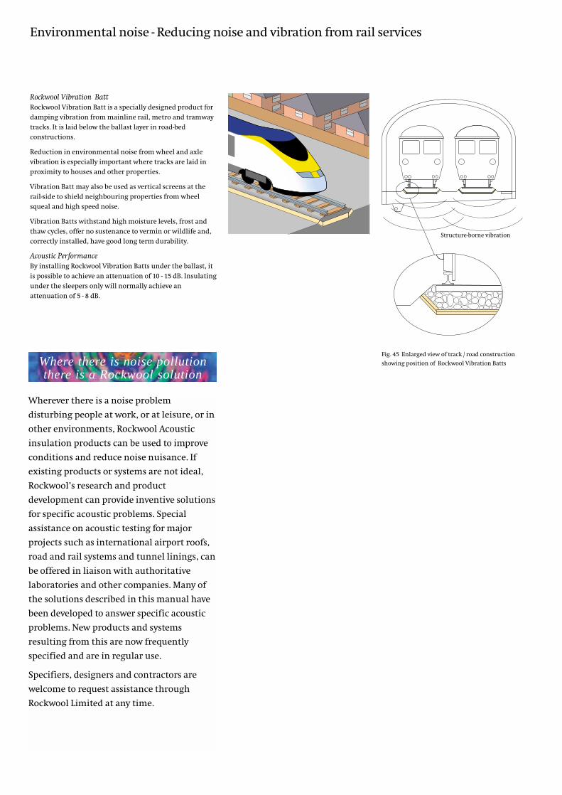
Rockwool Vibration BattRockwool Vibration Batt is a specially designed product for
damping vibration from mainline rail, metro and tramway
tracks. It is laid below the ballast layer in road-bed
constructions.
Reduction in environmental noise from wheel and axle
vibration is especially important where tracks are laid in
proximity to houses and other properties.
Vibration Batt may also be used as vertical screens at the
rail-side to shield neighbouring properties from wheel
squeal and high speed noise.
Vibration Batts withstand high moisture levels, frost and
thaw cycles, offer no sustenance to vermin or wildlife and,
correctly installed, have good long term durability.
Acoustic PerformanceBy installing Rockwool Vibration Batts under the ballast, it
is possible to achieve an attenuation of 10 - 15 dB. Insulating
under the sleepers only will normally achieve an
attenuation of 5 - 8 dB.
Fig. 45 Enlarged view of track / road construction
showing position of Rockwool Vibration Batts
Environmental noise - Reducing noise and vibration from rail services
Wherever there is a noise problem
disturbing people at work, or at leisure, or in
other environments, Rockwool Acoustic
insulation products can be used to improve
conditions and reduce noise nuisance. If
existing products or systems are not ideal,
Rockwool’s research and product
development can provide inventive solutions
for specific acoustic problems. Special
assistance on acoustic testing for major
projects such as international airport roofs,
road and rail systems and tunnel linings, can
be offered in liaison with authoritative
laboratories and other companies. Many of
the solutions described in this manual have
been developed to answer specific acoustic
problems. New products and systems
resulting from this are now frequently
specified and are in regular use.
Specifiers, designers and contractors are
welcome to request assistance through
Rockwool Limited at any time.
Structure-borne vibration
Where there is noise pollutionthere is a Rockwool solution

Alphabetical index
Subject/product Page No.Absorption coefficients of Rockwool materials 6
Access Floor FireStop 17
Acoustic Elements 23
Acoustic Floor System 16
Acoustic enclosure 7, 22
Acoustic linings 7
Acoustic lining to plant room 22
Acoustic Mat 18
Acoustic Panel Wall Lining System 23
Acoustic Party Wall dpc 11
Acoustic Slab 10 - 15
Air conditioning and ventilation ductwork 24
Ambient noise levels 6
Building Regulations, Part E 4, 5, 11, 15
Building Regulations (floors and partitions) 15
Cladding Roll 19
Composite Panels 19
Control of noise levels 5-7
Duct insulation 24
Duct penetration 25
Enclosing noisy plant and machinery 22
Environmental noise 26
Fire Barrier 17
Flanking transmission 5
Floating floor construction 16
Hardrock Roofing Boards 19
Health and Safety at Work 4
High Impact Liner Board 18
Incidental improvement 5
Industrial processes 22
Intermediate floors 15, 16
Internal noise levels 18
Internal partitions 12 - 14
Internal partitions (flanking transmission) 17
Isolation of plant noise 22
Lamella Floor Units 16
Liner Board 10
Lightweight metal stud partitions 12, 13
Neighbourhood noise 5
Noise from outside 4
Noise from pipework and services 26
Noise from plant and equipment 7, 22
Noise measurement 2
Overhead noise 5
Partitions 12 - 14
Pipes and ductwork 7
Process Pipe Sections 7
Product selector - industrial 20
Product selector - commercial and residential 8
Rail transport noise 26
Reducing noise levels 6
Rigid Slabs 22
Rockfloor 16
RW3 tissue faced slabs 24
Separating walls 10
Services penetrations 7, 25
Steel faced partitions 12
Soffit Liner 18
Sound absorption 6
Sound Absorption Board 18
Sound reasons for acoustic insulation 3
Techwrap 24
Timber Batt 11
Timber framed separating walls 11
Timber stud partitions 14
Transmission loss 5
Upgrading existing separating walls 10
Upgrading existing floors 15
Vibration Insulation Batt 26
Wall-mounted acoustic control 23
Wired Mats 22, 25

Rockwool Limited reserves the right
to alter or amend the specification of
products without notice as our policy
is one of constant improvement.
The information contained in this
data sheet is believed to be correct
at the date of publication. Whilst
Rockwool will endeavour to keep its
publications up to date, readers will
appreciate that between publications
there may be pertinent changes in the
law, or other developments affecting
the accuracy of the information
contained in this data sheet.
The above applications do not
necessarily represent an exhaustive
list of applications for Firebatt 825.
Rockwool Limited does not accept
responsibility for the consequences of
using Firebatt 825 in applications
different from those described above.
Expert advice should be sought where
such different applications are
contemplated, or where the extent of
any listed application is in doubt.
Rockwool Limited
Pencoed. Bridgend. cf35 6ny
t 01656 862621
f 01656 862302
www.rockwool.co.uk
Designed and produced by
Communication Design Partnership
Printed by APB Colour Print Ltd.
F I R E S A F E I N S U L A T I O N
Technical services
Rockwool technical staff with expertise in all aspects of
acoustic, thermal and fire performance are always ready to
give help and advice on any matters concerned with the
acoustic applications of Rockwool products.
All Rockwool products are dealt with by their respective
Divisions, which include those for Building, Systems, and
Industrial.
References
This is one of a series of Rockwool Manuals, Data Sheets and
other technical publications covering the complete range of
Rockwool insulation products.