firewall - usg boral€¦ · · 2017-09-08boral is a leading australian supplier of building and...
TRANSCRIPT
AREA SEPARATION WALLS FOR INDUSTRIAL BUILDINGS
BORAL PLASTERBOARDBuild something great™
Firewall®
www.boral.com.au/firewall PB235 April 2013
2 April 2013 | BORAL PLASTERBOARD
Firewall®
Boral’s Purpose …
to create sustainable solutions for a worldwide building and construction industry.
Boral is a leading Australian supplier of building and construction
materials, operating also throughout Asia and in the Unites States.
Boral offers a wide range of building solutions for the residential,
commercial and infrastructure sectors, including Bricks, Roof Tiles,
Plasterboard, Concrete, Asphalt and many others. Information on
the full range of Boral products can be found at www.boral.com.au
Boral Plasterboard specialises in the manufacture, distribution
and installation of plasterboard based wall and ceiling systems. In
Australia, Boral operates plasterboard manufacturing facilities in
New South Wales, Queensland and Victoria. Boral Plasterboard also
operates Australia-wide distribution network of company owned
stores and independent resellers.
Striving to create sustainable building solutions for a worldwide
building and construction industry, Boral aims to reduce the
impact of its operations on the environment and to make a positive
difference to the communities in which it operates.
Boral Plasterboard prides itself on its leadership in the area of
lightweight building solutions.
Among the successful solutions introduced by the company
over the years are: Partiwall® and IntRwall® separating wall
systems, OutRwall® and FireClad® fi re rated exterior wall systems,
CinemaZone® acoustic walls and ceilings for home cinemas, and
many others.
Boral Plasterboard’s Product and Systems Development (PSD) team
boasts unrivalled expertise in lightweight fi re rated and acoustic
systems, and routinely works with customers to select and, if
required, tailor solutions for specifi c projects.
Together with the TecASSIST® customer help line, Boral
Plasterboard’s PSD team is well positioned to provide technical
support to projects of any size and complexity.
For expert advice on lightweight Building Systems, contact Boral
TecASSIST® 1800 811 222.
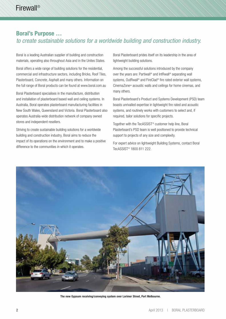
The new Gypsum receiving/conveying system over Lorimer Street, Port Melbourne.

3BORAL PLASTERBOARD | April 2013
Firewall®
Contents
Introduction 3
Design Issues 4
What Happens in a Fire? 4
What About Acoustics? 5
Firewall® System Types 6
Design 7
Structural Design 7
Materials 7
Single and Twin Stud Wall Firewall® Systems 8
Fire Design 8
Single Stud Firewall® Systems - System Selector 9
Twin Stud Firewall® Systems - System Selector 10
D-Stud™ Wall System 11
Non Load Bearing D-Stud™ Walls 11
D-Stud™ - System Selector 12
Details 13
Base Detail of Single Stud Wall 13
Base Detail of Twin Stud Wall 13
Single Stud Wall Head Elevation - Perpendicular to Portal Frame 13
Wall Running Below Purlins 14
Wall Running Between Purlins 14
Single Stud Wall Head Section Parallel to Portal 15
Single Stud Wall Head Parallel to Portal 15
Twin Stud Wall Head Section Parallel to Portal 16
Twin Stud Wall Head Section Perpendicular to Portal 16
Wall Junction With External Metal Clad Non Fire Rated Wall 17
Wall Junction With External Pre-Cast Concrete Panel Wall - No Cleats 17
Wall Junction With External Pre-Cast Concrete Panel Wall - Using Cleats 17
Treatment of Steel Members Penetrating Firewall® 18
Impact Protection 18
Wall With Steel Sheet Between Plasterboard Layers 19
Wall With Mesh Reinforcement 19
Section D - Wall With Mesh Reinforcement 19
Head Detail for Non Load Bearing 4 Hour Wall 20
Section E - Non Load Bearing 4 Hour Wall 21
Wall "T" Intersection - Non Load Bearing 4 Hour Wall 21
4 Hour Wall Base Detail 22
Linerstrip® Fixing Detail 22
Construction Notes 23
Approved Sealants 23
Contacts and Further Information
Sustainability 24
Health and Safety 24
Technical Enquiries 24
Sales Enquiries 24
IntroductionFirewall® Area Separation Walls are recommended for use in
buildings that have a steel roof structure such as warehouses,
cinemas and factories. Firewall® Area Separation Walls can be
utilised in the retail, commercial and industrial sector to provide
sub-divisions or fi re compartments within a building envelope.
These walls can be fi re rated up to 4 hours (non-load bearing) and
have acoustic ratings up to Rw = 78dB.
This brochure will give the reader an understanding of:
• How a building with a steel roofing system can behave
in a fire.
• The design issues when specifying Firewall® Area
Separation Walls.
• What systems are available to meet the designer’s
requirements.
• How to detail the plasterboard application to achieve the
required performance when installed.

4 April 2013 | BORAL PLASTERBOARD
Firewall®
What Happens in a Fire?
When dividing a building having a sheet roof into two or more fi re
compartments, the fi re-rated wall system selected is often assumed
to be non-load bearing as the structure is already standing. The
fi re walls are thought of only as ‘infi ll’ walls. This assumption is true
before a fi re.
However, if a fi re should occur, structural roof components exposed
to the fi re may lose their strength requiring the adjacent ‘non-load
bearing’ wall to support the dead load of these structural roof
components and any loadings generated by structural components
on the unaffected side of the fi re wall.
As shown in the following diagrams, a fi re begins in one of the
areas in the steel framed building separated from the adjacent area
with a fi re rated wall running perpendicular to portal frame.
As the fi re continues and temperature increases, it can cause the
steel in the portal frame to lose strength and sag under its own
weight. As a consequence, the fi re rated dividing wall may be
required to carry the loads of the collapsing section of the portal
and the unaffected part of the portal frame.
If the fi re rated wall is unable to carry these imposed loads and
were to collapse then the fi re would no longer be contained within
the fi re compartment and spread to the rest of the building.
Design Issues
A similar situation will occur when the fi re wall runs parallel to the
portal roof beams whereby the dead loads of the fi re affected portal
frames may be transferred into the fi re wall via the roof purlins
spanning from portal frame to portal frame.
When designing the wall to support the imposed axial loads during
a fi re, the Engineer needs to be aware that the fi re rated wall may
bow out of plane as the heat affects the studs. In steel stud walls
the wall tends to bow toward the fi re as the stud fl ange closest
to the fi re heats up. This may have an impact on the axial load
carrying capacity of the stud due to ‘P-delta’ effects. The presence
of the plasterboard insulates the stud fl anges slowing the heating
process and the amount of bowing in the wall.
A further issue to be considered by the designer is the conduction
of heat along steel members that penetrate the fi re rated Area
Separation Wall. Steel is a very good conductor of heat and
precautions need to be taken to ensure that combustible material in
contact with the steel member does not catch fi re.
Fire testing undertaken at Victoria University of Technology in
conjunction with Bluescope Steel and OneSteel examined how heat
fl ows along steel members passing through Boral plasterboard
walls and what simple methods could be employed to prevent the
steel reaching temperatures that could allow a fi re to cross the
Firewall® Area Separation Wall – refer construction details on pages
15-22 of this publication.
Note:
Refer CSIRO Assessment FCO-2440 'Industrial Wall Systems' for certification of Firewall systems and behaviour of Boral plasterboard in fire conditions outlined in this publication.

5BORAL PLASTERBOARD | April 2013
Firewall®
» Design Issues
What About Acoustics?
The acoustic performance of a wall is measured by a term called
the Weighted Sound Reduction Index, Rw and is expressed as a
single number rating. The higher the Rw the better the wall is in
preventing sound passing through it.
The Rw alone is not a good indicator of how well the partition
isolates low frequency (bass) sounds which may be an important
factor when choosing an appropriate area separation wall system.
To choose a wall with improved low frequency performance, the
Rw + Ctr should be considered. For instance, the Building Code
of Australia requires specifi c walls separating dwellings to have a
minimum Rw + Ctr = 50 dB.
This may be a good starting point for factories where noisy
machinery is being used and an area separation wall is required to
reduce sound to a level that does not annoy the occupants on the
other side.
For walls dividing cinemas, a typical Specifi cation has required the
performance of the wall to be a minimum Rw = 65dB with particular
emphasis on noise reduction performance in selected octave band
centre frequencies. The D-Stud™ system has been successfully
used on many Cinema projects.
The higher the Rw + Ctr value the better the sound isolation
performance, particularly in the low frequencies.
The amount of sound isolation a wall provides is a function of:
• Mass of plasterboard on each side
• Size of the wall cavity
• Whether cavity insulation is present
• If there is a connection between the linings from one side
to the other.
Sound isolation can be improved by adding more layers of
plasterboard, increasing the wall cavity and adding insulation into
the wall cavity. For greater performance, it is important that there
is no mechanical linkage between the plasterboard leaves from one
side of the wall to the other. This can be achieved through using
either the Twin Stud wall system or the Boral D-Stud™ wall system.
The diagram below provides an indication of the Rw rating as it
relates to speech isolation. For example speech will be heard
through a partition that has an Rw = 36dB rating.
Typical Rw Ratings
(10mm plasterboard each side of stud wall is approx Rw = 36dB)
Rw(dB)
Noise Source
Normal speech can be heard easily
Loud speech can be heard easily
Loud speech can be heard, but not understood
Loud speech can be heard only as a murmur
Must strain to hear loud speech
Only some loud speech can be barely heard
Loud speech cannot be heard
25
30
35
42
45
48
50

6 April 2013 | BORAL PLASTERBOARD
Firewall®
Firewall System Types
Single stud walls comprise steel studs, lined on both sides of the
stud with plasterboard. Rows of noggings or bridging are normally
required to provide stability to the stud section.
The fi re rating will be dependent upon the number of layers of
plasterboard fi xed to the studwork.
The walls are usually non load bearing, but can be designed to
carry axial loads. The size of the studs will be dependent upon
the anticipated design loadings and should be determined by a
Structural Engineer. Load bearing members can be installed within
the wall cavity and be protected by the plasterboard linings on each
side of the wall.
Single Stud Walls
Twin Stud Walls
D-Stud™ Walls
Twin stud walls comprise two sets of steel studs, each one lined on
one side only with plasterboard. Rows of noggings or bridging are
required to provide stability to the stud section.
Twin stud walls can be used where improved acoustic performance
is required or the wall width is dictated by the size of steel columns
or other fi xtures present within the wall cavity.
The fi re rating will be dependent upon the number of layers of
plasterboard fi xed to the studwork. The size of the studs will be
dependent upon the anticipated design loadings and should be
determined by a Structural Engineer.
D-Stud™ walls are non load bearing and can be used where
increased acoustic performance is required, especially in Cinemas.
The D-Stud™ wall system does not need nogging or bridging
between the studs. and allows stud centres greater than 600mm
max centres.
The system with four layers of 16mm Boral Firestop® on each side,
cavity insulation and an overall width of 500mm has been used at
the Chadstone Cinemas in Victoria.
Note:
D-Stud™ systems are subject to Australian Patent Number 697958

7BORAL PLASTERBOARD | April 2013
Firewall®
Structural Design
When designing Firewall® Area Separation Walls, the Engineer
must consider the lateral pressures that may be exerted upon the
wall. With most factory/warehouse type buildings, they often have
large doorways to facilitate the loading and unloading of trucks.
These large or ‘dominant’ openings allow the air pressure within the
building to respond more quickly to the external environment than
would occur if the building had small openings or was sealed. The
building designer will need to take these loads into account when
designing the structure of the building, especially in regards to the
lateral loadings that the wall may apply to the bottom chords of roof
beams or purlins supporting the top of the walls.
For this reason the connections between the top of area separation
wall and the supporting structure have to have a greater capacity
than those normally used for fi re rated walls where light gauge
defl ection head tracks are used. Similarly the base connections will
also have to be capable of resisting the internal pressures acting on
the wall.
If the wall is to be non-load bearing (except in fi re service) then
the Engineer has to ensure that an appropriate defl ection head is
selected that will allow for any upward or downward defl ections in
the roof so that the wall will not impact upon the existing structure
as it was originally designed to perform.
For fi re rated walls running perpendicular to portal frames or roof
beams, additional structural columns may be required to support
the roof structure during a fi re event.
Similarly, for fi re rated walls running parallel and not to full length
of main roof structure additional columns may be required. Refer
construction details in pages 15-22.
The Engineer must consider appropriate wall bracing systems
to account for any racking loads exerted on the separation wall,
in particular walls running parallel to portal frames. At no time
must the plasterboard be assumed to provide bracing to the
separation wall.
The Building Code of Australia sets out minimum defl ection criteria
in Specifi cation C1.8 for fi re rated walls depending upon the
purpose of the wall. For ‘walls generally’ the defl ection criteria is
height/240 to a maximum of 30mm when the wall is subjected to
a design load of 250Pa. This means that all walls over 7.2m
in height under this classifi cation have a maximum allowable
defl ection of 30mm.
If the wall forms part of a fi re escape passageway, then the design
load is increased to either 350Pa or 1kPa depending upon the use
of the building.
Materials
All materials must be delivered in their original unopened packages
where appropriate and stored clear of the ground in an enclosed
shelter providing protection from damage and exposure to the
elements. Damaged or deteriorated materials must be removed
from site.
The stud sections and fi xing details used to build the wall are to
be designed by a Structural Engineer to resist the design loads
determined to be acting upon the wall before, during and after
a fi re.
For details of D-Stud™ wall systems refer to current Boral
Plasterboard technical literature.
Boral Linerstrip LS1® has been developed to simplify installation of
Shaftliner™ plasterboard.
Note:
Linerstrip LS1® sections are subject to Australian Registered Design Numbers 302762, 302763 and 302765 and New Zealand Registered Design Numbers 406256, 406258 and 406259
Design
Linerstrip LS1®
0.75mm BMTGalvanised Mild Steel

8 April 2013 | BORAL PLASTERBOARD
Firewall®
Fire Design
The following board confi gurations to each side of single stud wall
or twin stud wall may be used for load bearing and non load bearing
fi re rated walls achieving the FRL’s stated under the conditions
listed in the table below.
Where walls are non load bearing and columns used to support the
structure during or after a fi re require fi re protection, the designer
should refer to the Boral Plasterboard Column and Beam Protection
Systems brochure.
Notes:
• For load bearing walls with up to 2 layers of 16mm Firestop®
on each side, all joints in the first layer to be backed by
nogging or studs. Elsewhere noggings to be provided at
1200mm maximum centres.
• Bracing to be provided within the wall as required by Structural
Engineer ignoring plasterboard contribution.
• Cold formed steel wall studs to be designed by a suitably
qualified Structural Engineer and shall comply with
AS/NZS 4600:1996 Cold Formed Steel Structures.
• Any structure providing support, including lateral support,
to the load bearing wall must have an FRL of at least that of
the wall (assuming that the particular structure will be required
to provide the support whilst being exposed to the fire).
• 25mm Shaftliner™ sheets fixed to wall studs using
Linerstrip LS1®.
• Stud splicing not allowed.
• Unless noted otherwise, walls to be lined to standard Boral
Plasterboard non load bearing fire rated details.
• Construction details contained in this brochure have been
assessed by CSIRO FCO-2765, refer to report for fire
performance.
• It is the Designer's/Builder's responsibility to ensure
that systems and details contained in this brochure
meet their project requirements and specifications.
Board Confi guration
Firestop®
FRL Fire Attack DirectionSide 1 Side 2
1x13 1x13 30/30/30 Both
1x16 1x16 60/60/60 Both
2x13 2x13 90/90/90 Both
2x16 2x16 120/120/120 Both
1x25*
1x16
1x25*
1x16 120/120/120 Both
1x25*
1x16
1x25*
1x16 -/180/180 Both
2x25*
1x16
2x25*
1x16 180/180/180 Both
2x25*
1x16
2x25*
1x16 -/240/240 Both
* Denotes 25mm thick Shaftliner™ with Linerstrip LS1®
Single and Twin Stud Firewall® Systems

9BORAL PLASTERBOARD | April 2013
Firewall®
• Wall system thumbnails are for illustrative purposes only • Acoustic ratings based on 2.0mm BMT studs at 600mm centres by Graeme Harding & Associates
• 100G14 denotes 100mm thick glasswool insulation, min density 14kg/m3 • 100P14 denotes 100mm thick polyester insulation, min density 14kg/m3
S1313F
1 layer 13mm Firestop®
each side of frame
150 Refer
Engineer
21.0 30/30/30
Both sidesFCO-1045
38 — Nil
200 21.0 39 — Nil
150 21.0 41 33 100G14, 100P14
200 21.0 42 34 100G14, 100P14
S1616F
1 layer 16mm Firestop®
each side of frame
150 Refer
Engineer
26.0 60/60/60
Both sidesFCO-1045
39 — Nil
200 26.0 40 — Nil
150 26.0 42 34 100G14, 100P14
200 26.0 43 35 100G14, 100P14
S2626F
2 layers 13mm Firestop®
each side of frame
150 Refer
Engineer
42.0 90/90/90
Both sidesFCO-1045
43 — Nil
200 42.0 44 — Nil
150 42.0 47 42 100G14, 100P14
200 42.0 48 43 100G14, 100P14
S3232F
2 layers 16mm Firestop®
each side of frame
150 Refer
Engineer
52.0 120/120/120
Both sidesFCO-1045
43 — Nil
200 52.0 44 — Nil
150 52.0 47 42 100G14, 100P14
200 52.0 48 43 100G14, 100P14
S4141F
Linerstrip LS1® 1x25 Shaftliner™ and
1x16 Firestop® each side of frame
150 Refer
Engineer
67.0 120/120/120
-/180/180
Both sidesFCO-2440
47 — Nil
200 67.0 48 — Nil
150 67.0 51 46 100G14, 100P14
200 67.0 52 47 100G14, 100P14
S6666F
Linerstrip LS1® 2x25 Shaftliner™ and
1x16 Firestop® each side of frame
150 Refer
Engineer
108.5 180/180/180
-/240/240
Both sidesFCO-2440
50 — Nil
200 108.5 50 — Nil
150 108.5 55 50 100G14, 100P14
200 108.5 55 50 100G14, 100P14
Assembly System Reference
NomCavityWidth
(mm)
Stud
Size(mm)
Pbd
Weight(kg/m2)
Fire
FRLBasis
Acoustic Ratings
Rw Rw+Ctr Insulation
» Single Stud Firewall® Systems
Cavity
width
Specified plasterboard
Cavity
width
Specified plasterboard
Cavity
width
Specified plasterboard

10 April 2013 | BORAL PLASTERBOARD
Firewall®
• Wall System thumbnails are for illustrative purposes only • Acoustic ratings based on 2.0mm BMT studs at 600mm centres by Graeme Harding & Associates
• 200G14 denotes 200mm thick glasswool insulation, min density 14kg/m3 • 200P14 denotes 200mm thick polyester insulation, min density 14kg/m3
ST1313F
1 layer 13mm Firestop®
each side of frame
350 Refer
Engineer
21.0 30/30/30
Both sidesFCO-1045
42 — Nil
400 21.0 43 — Nil
450 21.0 44 — Nil
350 21.0 55 46 200G14, 200P14
400 21.0 56 47 200G14, 200P14
450 21.0 56 49 200G14, 200P14
ST1616F
1 layer 16mm Firestop®
each side of frame
350 Refer
Engineer
26.0 60/60/60
Both sidesFCO-1045
45 — Nil
400 26.0 46 — Nil
450 26.0 47 Nil
350 26.0 57 49 200G14, 200P14
400 26.0 57 50 200G14, 200P14
450 26.0 58 50 200G14, 200P14
ST2626F
2 layers 13mm Firestop®
each side of frame
350 Refer
Engineer
42.0 90/90/90
Both sidesFCO-1360
FCO-1045
51 — Nil
400 42.0 52 — Nil
450 42.0 53 Nil
350 42.0 66 58 200G14, 200P14
400 42.0 67 59 200G14, 200P14
450 42.0 68 60 200G14, 200P14
ST3232F
2 layers 16mm Firestop®
each side of frame
350 Refer
Engineer
52.0 120/120/120
Both sidesFCO-1360
FCO-1045
55 — Nil
400 52.0 56 — Nil
450 52.0 57 Nil
350 52.0 68 59 200G14, 200P14
400 52.0 69 60 200G14, 200P14
450 52.0 70 63 200G14, 200P14
ST4141F
Linerstrip LS1® 1x25 Shaftliner™
and 1x16 Firestop®
each side of frame
350 Refer
Engineer
67.0 120/120/120
-/180/180
Both sidesFCO-2440
58 — Nil
400 67.0 59 — Nil
450 67.0 60 Nil
350 67.0 72 63 200G14, 200P14
400 67.0 73 64 200G14, 200P14
450 67.0 74 65 200G14, 200P14
ST6666F
Linerstrip LS1® 2x25 Shaftliner™
and 1x16 Firestop®
each side of frame
350 Refer
Engineer
108.5 180/180/180
-/240/240
Both sidesFCO-2440
63 — Nil
400 108.5 64 — Nil
450 108.5 65 Nil
350 108.5 76 67 200G14, 200P14
400 108.5 77 68 200G14, 200P14
450 108.5 78 69 200G14, 200P14
» Twin Stud Firewall® Systems
Cavity
width
Specified plasterboard
Cavity
width
Specified plasterboard
Cav
ity w
idth
Specified plasterboard
Assembly System Reference
NomCavityWidth
(mm)
Stud
Size(mm)
Pbd
Weight(kg/m2)
Fire
FRLBasis
Acoustic Ratings
Rw Rw+Ctr Insulation
11BORAL PLASTERBOARD | April 2013
Firewall®
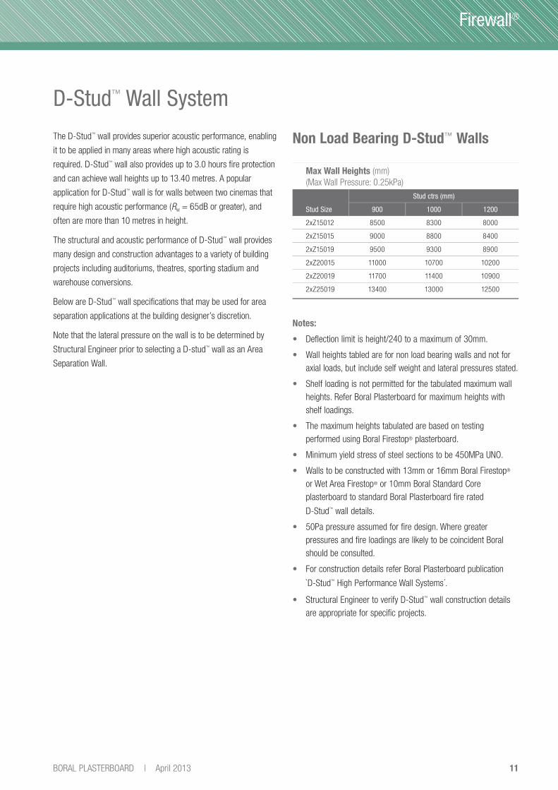
D-Stud™ Wall System
The D-Stud™ wall provides superior acoustic performance, enabling
it to be applied in many areas where high acoustic rating is
required. D-Stud™ wall also provides up to 3.0 hours fi re protection
and can achieve wall heights up to 13.40 metres. A popular
application for D-Stud™ wall is for walls between two cinemas that
require high acoustic performance (Rw = 65dB or greater), and
often are more than 10 metres in height.
The structural and acoustic performance of D-Stud™ wall provides
many design and construction advantages to a variety of building
projects including auditoriums, theatres, sporting stadium and
warehouse conversions.
Below are D-Stud™ wall specifi cations that may be used for area
separation applications at the building designer’s discretion.
Note that the lateral pressure on the wall is to be determined by
Structural Engineer prior to selecting a D-stud™ wall as an Area
Separation Wall.
Non Load Bearing D-Stud™ Walls
Notes:
• Deflection limit is height/240 to a maximum of 30mm.
• Wall heights tabled are for non load bearing walls and not for
axial loads, but include self weight and lateral pressures stated.
• Shelf loading is not permitted for the tabulated maximum wall
heights. Refer Boral Plasterboard for maximum heights with
shelf loadings.
• The maximum heights tabulated are based on testing
performed using Boral Firestop® plasterboard.
• Minimum yield stress of steel sections to be 450MPa UNO.
• Walls to be constructed with 13mm or 16mm Boral Firestop®
or Wet Area Firestop® or 10mm Boral Standard Core
plasterboard to standard Boral Plasterboard fire rated
D-Stud™ wall details.
• 50Pa pressure assumed for fire design. Where greater
pressures and fire loadings are likely to be coincident Boral
should be consulted.
• For construction details refer Boral Plasterboard publication
`D-Stud™ High Performance Wall Systems´.
• Structural Engineer to verify D-Stud™ wall construction details
are appropriate for specific projects.
Max Wall Heights (mm)
(Max Wall Pressure: 0.25kPa)
Stud Size
Stud ctrs (mm)
900 1000 1200
2xZ15012 8500 8300 8000
2xZ15015 9000 8800 8400
2xZ15019 9500 9300 8900
2xZ20015 11000 10700 10200
2xZ20019 11700 11400 10900
2xZ25019 13400 13000 12500

12 April 2013 | BORAL PLASTERBOARD
Firewall®
» D-Stud™ Wall System
System D4848F illustrated
D4848F
3 x 16mm Firestop® pbd layers
to each side of frame
500 Refer
Engineer
78.0 -/180/180FSV-1073
63 — Nil
500 78.0 74 65 200G14, 200P14
D4864F
3 x 16mm Firestop® pbd layers to
one side of frame
4 x 16mm Firestop® pbd layers
to other side
500 Refer
Engineer
91.0 -/180/180FSV-1073
64 — Nil
500 91.0 76 67 200G14, 200P14
D6464F
4 x 16mm Firestop® pbd layers
to each side of frame
500 Refer
Engineer
104.0 -/180/180FSV-1073
64 — Nil
500 104.0 77 68 200G14, 200P14
Note:
D-Stud™ systems are subject to Australian Patent Number 697958.
Assembly System Reference
NomCavityWidth
(mm)
Stud
Size(mm)
Pbd
Weight(kg/m2)
Fire
FRLBasis
Acoustic Ratings
Rw Rw+Ctr Insulation

13BORAL PLASTERBOARD | April 2013
Firewall®
Details
Base Detail of Single Stud WallNote: Refer to FCO-2765 for fire performance.
Single Stud Wall Head Elevation - Perpendicular to Portal Frame
Note:
Refer page 23 for construction notes.Refer to FCO-2765 for fire performance.
Base Detail of Twin Stud WallNote: Refer to FCO-2765 for fire performance.
Cavity insulation, if required
Cavity insulation, if required
150-2
00m
m o
verlap
Overlapping plasterboard cut in around
the beam and joined above and below the
beam. Joins in multiple layers of board to
be offset by 100mm min
Portal rafter
A, B similar. Refer p14
Stud section determined by
Structural Engineer
Cleat connecting base of stud to
concrete floor slab. Fixings
determined by Structural Engineer
dependent upon loadings on wall
Min 35 x 35 x 0.75mm bmt angle
fixed to purlin section or slab,
to fix plasterboard to and as a
backing to flexible fire rated sealant
10mm flexible fire rated sealant
between end of plasterboard
sheets and the floor slab
Base track section or pair of
angles sized according to wall stud
and fixed to concrete floor slab
with fixings determined by
Structural Engineer dependent
upon loadings on wall
10mm flexible fire rated sealant
between end of plasterboard
sheets and the floor slab
Stud sections determined
by Structural Engineer
Rockwool insulation compressed
between top edges of plasterboard
sheets and underside of roof sheeting
Structural roof framing behind
not shown for clarity
Wall framing behind not shown for clarity.
Where required provide 50x50x0.75mm
bmt angle to facilitate fixing of
plasterboard typical UNO
10 - 15mm wide flexible fire rated
sealant between beam and cut edges
of plasterboard layers

14 April 2013 | BORAL PLASTERBOARD
Firewall®
» Details
Portal rafter
Portal rafter
Purlin
Purlin
Stud section determined by
Structural Engineer
Screw fixings
Cleat designed by Structural
Engineer connecting top of stud
to supporting beam
0.75mm bmt angle fixed to
underside of roof beam to
fix plasterboard to
Cleat designed by Structural
Engineer connecting top of stud
to supporting beam
0.75mm bmt angle fixed
across underside of roof beam
flange to fix plasterboard to
If required column within wall cavity
designed by structural engineer to
carry dead loads imposed by roof
beam losing strength during a fire
event. Where column exceeds the
cavity width it shall be protected
using the appropriate column
protection system
Stud section determined
by Structural Engineer
Rockwool insulation compressed
between top edges of plasterboard
sheets and underside of roof sheeting
Custom rolled track section in
0.55mm bmt (minimum) to suit wall
width and roof pitch, and attached to
top or bottom flange of roof purlin at
600mm centres
Beam section designed by Structural
Engineer to span between roof beams
to support top of wall
Note:
Details shown do not consider the effects of sound
flanking paths at the head connection that may
detrimentally affect the overall acoustic performance of
the wall. If critical, it is recommended that the advice of
a noise and vibration isolation specialist be sought for
the design of an appropriate detail with due regard to
any imposed loadings that may need to be considered.
Typical for all head details published in this brochure.
Rockwool insulation compressed
between top edges of
plasterboard sheets and
underside of roof sheeting and
in space above purlin sections
0.75mm bmt angle fixed to purlin
section to fix plasterboard to
Beam section designed by
Structural Engineer to span
between roof beams to
support top of wall
0.75mm bmt angle fixed to
under side of roof beam to
fix plasterboard to
Purlin sections selected by
Structural Engineer screwed
together to form a 'T' section
to span between roof beams
supporting the top of the
plasterboard against the
underside of the roof sheeting
If required column within wall cavity
designed by Structural Engineer to carry
dead loads imposed by roof beam losing
strength during a fire event. Where
column exceeds the cavity width it shall
be protected using the appropriate
column protection system
Section A - Wall Running Below PurlinsNote: Refer page 23 for construction notes.Refer to FCO-2765 for fire performance.
Section B - Wall Running Between PurlinsNote: Refer page 23 for construction notes.Refer to FCO-2765 for fire performance.

15BORAL PLASTERBOARD | April 2013
Firewall®
» Details
C
C
Plasterboard cut around purlins.
See detail below
Refer section C below
Wall framing not shown for clarity
0.75mm bmt angles fixed to roof
beam to fix plasterboard to – typical
Screw fixing
Purlin
Portal rafter
Stud section determined by
Structural Engineer
Rockwool insulation
compressed between top edges
of plasterboard sheets and
underside of roof sheeting
If the separation wall runs the full length of the roof
beam between structural supports, the additional
columns may not be necessary as the beam
receives some fire protection by being within the
wall (Structural Engineer to confirm)
Cleat designed by Structural
Engineer connecting top of
studto supporting beamIf required column within wall
cavity designed by Structural
Engineer to carry dead loads
imposed by roof beam losing
strength during a fire event.
Where column exceeds the cavity
width it shall be protected using
the appropriate column
protection system
Plasterboard cut around the purlins with gaps
filled full-depth with flexible fire rated sealant.
Fill penetration with pieces of Firestop®
plasterboard, 150mm long and seal to lining
plasterboard with fire rated sealant
150m
m
over
lap
Single Stud Wall Head Section Parallel to PortalNote: Refer page 23 for construction notes.Refer to FCO-2765 for fire performance.
Section C - Single Stud Wall Head Elevation Parallel to PortalNote: Refer to FCO-2765 for fire performance.

16 April 2013 | BORAL PLASTERBOARD
Firewall®
» Details
Twin Stud Wall Head Section Parallel to PortalNote: Refer page 23 for construction notes.Refer to FCO-2765 for fire performance.
Twin Stud Wall Head Section
Perpendicular to PortalNote: Refer page 23 for construction notes.Refer to FCO-2765 for fire performance.
Screw fixings
Stud section determined by
Structural Engineer
Screw fixing
Purlin
Purlin
Portal rafter
Portal rafter
Plasterboard cut around purlins
Rockwool insulation
compressed between top
edges of plasterboard sheets
and underside of roof sheeting
0.75mm bmt angles fixed to
roof beam to fix plasterboard to
Overlap in plasterboard to be at least
15mm greater than the expected
deflection in the head (+ve or -ve).
Structural Engineer to advise
Cleat designed by Structural
Engineer connecting top of
stud to supporting beam
Stud section determined by
Structural Engineer
If required column within wall cavity designed
by Structural Engineer to carry dead loads
imposed by roof beam losing strength during
a fire event. Where column exceeds the cavity
width it shall be protected using the
appropriate column protection system
Beam section designed by
Structural Engineer to span
between roof beams to
support top of wall
Custom made track section in
0.75mm bmt (min) to suit wall
width and roof pitch, and attached
to top or bottom flange of roof
purlin at 600mm centres
0.75mm bmt angle fixed
to underside of beam to
fix plasterboard to
Cleat designed by Structural
Engineer connecting top of stud
to supporting beam
Rockwool insulation compressed
between top edges of plasterboard
sheets and underside of roof sheeting
If required column within wall cavity designed by
Structural Engineer to carry dead loads imposed
by roof beam losing strength during a fire event.
Where column exceeds the cavity width it shall
be protected using the appropriate column
protection system
Refer Section C
page 14 for details

17BORAL PLASTERBOARD | April 2013
Firewall®
» Details
Portal column
Portal column
Girt
150mm min overlap
50mm gap nom
150mm min overlap
150mm
Panel cleats
Portal column
50mm gap nom
150mm min overlap
50mm gap nomRockwool gasket
between stud and column flange
Plasterboard screw fixed to
continuous 0.75mm bmt angles
connected to flanges of column
Where cleats are installed to connect precast
panels to the columns, plasterboard layers
(300mm x 150mm) are to be screw laminated to
the previous layers until the cleat is obscured by
the plasterboard. A 10mm gap is to be left
between the plasterboard and the concrete which
is to be filled with a flexible fire rated sealant
10mm flexible fire rated sealant between
end of plasterboard sheets and the
pre-cast concrete panel external wall
Wall studs to Structural
Engineers details
Rockwool gasket
between stud and column flange
Plasterboard screw fixed to
continuous 0.75mm bmt angles
connected to flanges of column
10mm flexible fire rated sealant
between end of plasterboard
sheets and the pre-cast concrete
panel external wall
Rockwool insulation compressed
between edges of plasterboard sheets
and inside of metal wall sheeting
Plasterboard screw fixed to continuous
0.75mm bmt angles connected to the
flanges of the column
Voids formed around girt penetrations to
be filled with 150mm lengths of Firestop®
plasterboard and sealed to girts and
adjoining plasterboard with flexible fire
rated sealant
Wall studs to Structural
Engineer’s details
Rockwool gasket between stud
and column flangeWall Junction
With External Metal Clad
Non Fire Rated WallNote: Refer to FCO-2765 for fire performance.
Wall Junction With External Pre-cast Concrete Panel Wall - No CleatsNote: Refer to FCO-2765 for fire performance.
Wall Junction With External Pre-cast Concrete Panel Wall - Using CleatsNote: Refer to FCO-2765 for fire performance.
18 April 2013 | BORAL PLASTERBOARD
Firewall®
» Details
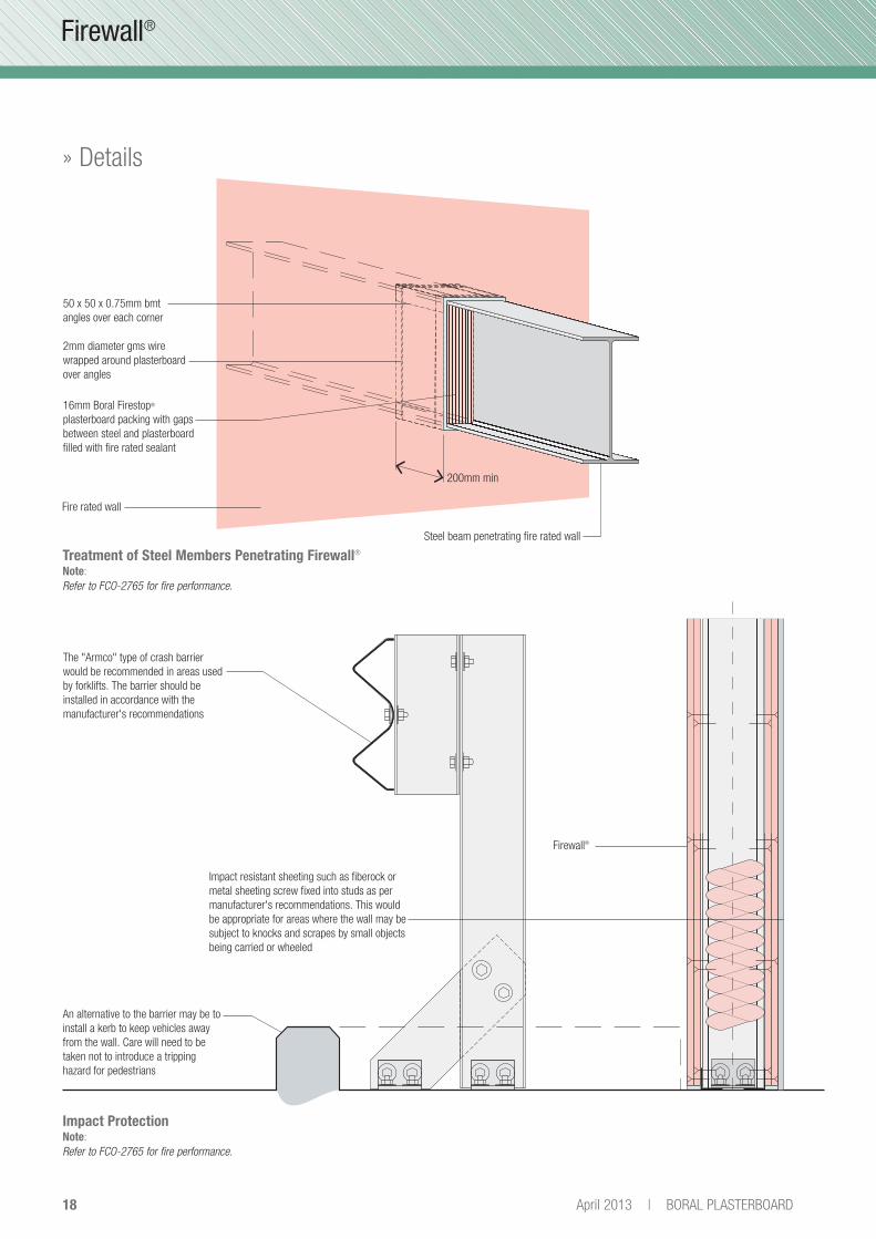
Firewall®
Steel beam penetrating fire rated wall
Fire rated wall
200mm min
50 x 50 x 0.75mm bmt
angles over each corner
2mm diameter gms wire
wrapped around plasterboard
over angles
16mm Boral Firestop®
plasterboard packing with gaps
between steel and plasterboard
filled with fire rated sealant
The "Armco" type of crash barrier
would be recommended in areas used
by forklifts. The barrier should be
installed in accordance with the
manufacturer's recommendations
Impact resistant sheeting such as fiberock or
metal sheeting screw fixed into studs as per
manufacturer's recommendations. This would
be appropriate for areas where the wall may be
subject to knocks and scrapes by small objects
being carried or wheeled
An alternative to the barrier may be to
install a kerb to keep vehicles away
from the wall. Care will need to be
taken not to introduce a tripping
hazard for pedestrians
Impact ProtectionNote: Refer to FCO-2765 for fire performance.
Treatment of Steel Members Penetrating Firewall®
Note: Refer to FCO-2765 for fire performance.

19BORAL PLASTERBOARD | April 2013
Firewall®
» Details
Cavity insulation if required
Firewall®
Cavity insulation if required
D D
2mm galvanised steel sheet
sandwiched between plasterboard
sheets and screw fixed to studs at
400mm maximum centres using
pan head screws
Outer layer of plasterboard can be
screwed to the steel sheet instead
of into the stud
Ceiling batten screwed to
stud with a fixing through
each flange of batten
200 x 200mm 7mm diameter mesh
with horizontal rods against face of
stud. Ceiling battens to be screw
fixed to the studs at 300mm centres
up the wall to fix the plasterboard to
Mesh held in place against stud
by batten section
22mm ceiling batten,
screw fixed to stud
Plasterboard
screw fixed to ceiling batten
Section D - Wall With Mesh Reinforcement
Wall With Steel Sheet Between Plasterboard LayersNote: Refer to FCO-2765 for fire performance.
Wall With Mesh ReinforcementNote: Refer to FCO-2765 for fire performance.

20 April 2013 | BORAL PLASTERBOARD
Firewall®
» Details
Head Detail for Non Load Bearing 4 Hour WallNote: Systems utilising Linerstrip LS1® sections are subject to Australian Patent Application Number 2006203282.Refer to FCO-2765 for fire performance.
E. Refer p 21
Portal rafter
Purlin
50 x 50 x 0.75mm angle
Rockwool insulation compressed
between top edges of plasterboard
sheets and underside of roof sheeting
Rockwool insulation across top of wall
to seal wall cavity from underside of
support beam extending up into the
beam cavity area on each side
Rockwool insulation 10mm thicker
than the width of the stud plus the gap
to the face of the wall sheet
150mm long pieces of Firestop®
plasterboard packing where lining
cannot be cut to fit 10mm away
from the roof purlin
Stud framing from minimum 64CS75
supported from the beam by angles
and with the head track section fixed
between roof purlins
50 x 50 x 0.75mm angle screw fixed
to stud framing to support horizontal
lengths of Shaftliner™
Overlap of wall stud by framing stud
on beam to be at least 100mm plus
the expected upward deflection of
the roof beam
50 x 50 x 0.75mm angle screw
fixed through Shaftliner™ into
previously fixed angle to provide
support to corner and horizontal
lengths of plasterboard
Horizontal plasterboard to butt
neatly into the vertical plasterboard
face to allow for vertical deflection
of roof beam
16mm Firestop® screw fixed
to Linerstrip LS1® flanges
@ 300mm max ctrs
Linerstrip LS1® supporting
Shaftliner screw fixed to wall stud
2 layers of Shaftliner™ fixed to wall
stud using Linerstrip LS1®. Second
layer offset by 300mm
Wall stud to
Structural Engineers details
Rondo P/N140's capping on each
shaftliner screw fixed to stud
Sawn edges of lengths of Shaftliner™
should rest against the face of the wall
sheet such that the gap should not
exceed 1mm
3 layers of 25mm Shaftliner™
to bottom of stud framing

21BORAL PLASTERBOARD | April 2013
Firewall®
» Details
Section E - Non Load Bearing 4 Hour Wall
Notes:
1. The wall studs should be sized by the Structural Engineer designing the structure
and be capable of withstanding lateral pressure loads and axial forces that will act
on the wall before and after a fire event.
2. For a four hour non load bearing wall (-/240/240), 2 layers of Shaftliner™
supported by Linerstrip LS1® with a single layer of 16mm Firestop® screw fixed
to the Linerstrip LS1® supporting the outer layer of Shaftliner™ on each side of
the wall.
3. The width that the higher plasterboard overlaps the lower plasterboard to be
100mm plus the expected deflection due to uplift of the roof beam.
4. The plasterboard should be installed in accordance with Boral Plasterboard's
standard requirements for fire rated wall.
5. The wall studs to be installed at 600mm maximum centres.
Plasterboard cut around purlins, with
gaps filled full depth with flexible fire
rated sealant.
Fill the void with pieces of Firestop®
plasterboard 150mm long and seal to
lining plasterboard with fire rated sealant
Rockwool compressed between the top
of the stud wall and plasterboard and
the underside of the roof sheeting
Wall "T" Intersection - Non Load Bearing 4 Hour WallNote: Refer to FCO-2765 for fire performance.
Cen
trel
ine
of r
oof
beam
abo
ve
Roo
f be
am s
pan
dire
ctio
n
Purlin span direction
25mm Shaftliner™
16mm Firestop®
Studs to Structural Engineers details
If required column within wall cavity designed
by Structural Engineer to carry dead loads
imposed by roof beam losing strength during
a fire event. Where column exceeds cavity
width it shall be protected using the
appropriate column protection system
End stud of intersecting wall to be
screw fixed through plasterboard
intoa stud specifically placed where
intersection occurs at 600mm
maximum centres vertically
10mm wide gap filled with flexible
fire rated sealant to full depth

22 April 2013 | BORAL PLASTERBOARD
Firewall®
Cavity insulation, if required
300m
m t
ypic
al
25mm Shaftliner™ sheets
Stud section determined
by Structural Engineer
Rondo PN140 sections encasing
bottom edge of Shaftliner™ panels
resting on floor slab and screw
fixed into stud section.
First layer Linerstrip LS1® at 600mm
ctrs up the wall fixed directly to the stud
to support first layer of Shaftliner™ Refer
below for fixing details
16mm Firestop® screw fixed to
Linerstrip LS1® at 300mm maximum ctrs
Second layer Linerstrip LS1® at 600mm ctrs
up the wall fixed through previous
Shaftliner™ and into stud section. Second
layer Linerstrip LS1® to be staggered 300mm
from first layer Linerstrip LS1® typical
First outer layer of Shaftliner™ to be
cut in half only each side
Cleat connecting base of stud to
concrete floor slab. Fixings determined
by Structural Engineer dependent upon
loadings on wall
10mm flexible fire rated sealant
between end of 16mm Firestop®
plasterboard and floor slab
First layer Linerstrip LS1® fix with
10 x 16 wafer head DP screw to all
studs. Second layer Linerstrip LS1®
fix with a 10 x 45 wafer head DP screw
to all studs. End of Linerstrip LS1® to
be butt joined on wall stud and screw
fixed to each end typical UNO
Note:
Systems utilising Linerstrip LS1® sections are subject to Australian Patent Application Number 2006203282
» Details
Linerstrip LS1® Fixing Detail
4 Hour Wall Base DetailNote: Refer to FCO-2765 for fire performance.

23BORAL PLASTERBOARD | April 2013
Firewall®
• The slotted holes in the cleats supporting wall studs and the
spigot connection on the beam supporting column to allow the
roof system to deflect without applying axial loading onto the
wall. The length of the slots in the cleats and the spigot will be
subject to +ve and –ve deflections in the structure and should
be sized by project Structural Engineer.
• The number of layers and type of plasterboard used will be
dependent upon the fire or acoustic performance required from
the system.
• The width that the higher plasterboard overlaps the lower
plasterboard to be 150mm minimum.
• The plasterboard shall be installed in accordance with Boral
Plasterboard’s standard requirements for fire rated walls.
• The wall studs to be installed at 600mm maximum centres
unless approved otherwise by Boral Plasterboard.
• Unless detailed or specified, penetrations in Firewall® Area
Separation Walls should be referred to Boral Plasterboard for
assessment prior to commencement of work.
• Control joints should be provided in long continuous runs
of area separation walls at 12 metre centres maximum and
wherever structural expansion joints are located. Control joints
to be verified by Structural Engineer prior to commencement
of work. Refer to standard Boral Plasterboard fire rated wall
systems for details.
Construction Notes
Approved Sealants
The following fi re grade sealants can be used in the installation
of the Firewall® Area Separation Wall systems:
Approved Fire Grade Sealants
Product Name Manufacturer
Fyreflex sealant Grinnel
Promaseal Mastic Promat
Lorient Fire Sealant Lorient
Multiflex Pyropanel
Fireban 1 Bostik
FireSound HB Fuller
BCC 06196 Apr13(Rebrand of 05160)
BLA 11Apr2013
Sales Enquiries 1800 003 377ACT 7 Barrier Street, Fyshwick 2609 F: (02) 6280 5816
New South Wales 3 Thackeray Street, Camellia 2142 F: (02) 9638 5557
Northern Territory Coonawarra Road, Winnellie 0820 F: (08) 8984 3778
Queensland 22 Kirra Street, Pinkenba 4008 F: (07) 3115 7321
South Australia 39 Burleigh Avenue, Woodville North 5012 F: (08) 7002 6381
Tasmania 93 Albert Road, Moonah 7009 F: (03) 6278 9865
Victoria 251 Salmon Street, Port Melbourne 3207 F: (03) 9214 2192
Western Australia 41 Rudderham Drive, North Fremantle 6159 F: (08) 6226 9833
Export Department 251 Salmon Street, Port Melbourne 3207 F: (03) 9214 2192
T: (03) 9214 2121
SustainabilityBoral Plasterboard aims to minimise the environmental impact of its operations and to make a positive difference to the environment and
communities in which it operates. Plasterboard is manufactured from abundant natural gypsum resources and 100% recycled paper liner.
Plasterboard waste can be recycled back into new plasterboard or used as a soil conditioner. Please contact Boral Plasterboard regarding
waste collection services available in your region.
Technical Enquiries 1800 811 222TecASSIST® provides technical advice to builders, architects, contractors, engineers, regulators and home owners throughout Australia.
Our friendly team can offer both practical and design input at all levels of the plasterboard industry. Get your next project off on the right track
by contacting TecASSIST® weekdays 8.30am - 4.30pm AEST on 1800 811 222 or www.boral.com.au/tecassist.
Health and SafetyFor information regarding the safe use of Boral Plasterboard products and accessories please refer to instructions on the product packaging
or contact your local Boral Plasterboard Sales Offi ce or TecASSIST® for a current copy of the Material Safety Data Sheet.
www.boral.com.au/firewallBoral, the Boral Logo and boral.com.au, Firewall®, Partiwall®, IntRwall®, OutRwall®, Fireclad®, Cinemazone®, Firestop® and Linerstrip® are
registered trade marks of Boral Australian Gypsum in Australia, other countries, or both. If these and other Boral trade marks are marked
on their fi rst appearance in this information with trade mark symbols ( ® or ™ ), these symbols indicate Australian registered or common law
trade marks owned by Boral and others at the time this information was published. Such trade marks may also be registered or common
law marks in other countries.
© Copyright Boral Limited 2013
This technical information is intended to provide general information on plasterboard products and should not be a substitute for
professional building advice. We recommend you use a qualifi ed person to install Boral plasterboard. Illustrations in this guide are
only representative of Boral plasterboard products and the appearance and effects that may be achieved by their use. To ensure the
information you are using is current, Boral recommends you review the latest building information available on the Boral website. For
further information contact TecASSIST® or your nearest Boral Plasterboard Sales Offi ce.