first lasing from a high power cylindrical grating smith...
TRANSCRIPT

FIRST LASING FROM A HIGH POWER CYLINDRICAL GRATING SMITH-PURCELL DEVICE*
H.P. Bluem#, R.H. Jackson, J.D. Jarvis, A.M.M. Todd, Advanced Energy Systems, Princeton, NJ, USA J. Gardelle, P. Modin, CEA-CESTA, Le Barp cedex, France
J. T. Donohue, CENBG, Gradignan, France Abstract
Many applications of THz radiation remain impractical or impossible due to an absence of compact sources with sufficient power. A source where the interaction occurs between an annular electron beam and a cylindrical grating is capable of generating high THz power in a very compact package. The strong beam bunching generates significant power at the fundamental frequency and harmonics. A collaboration between Advanced Energy Systems and CEA/CESTA has been ongoing in performing proof-of-principle tests on cylindrical grating configurations producing millimeter wave radiation. First lasing was achieved in such a device. Further experiments performed with a 6 mm period grating produced fundamental power at 15 GHz, second harmonic power at 30 GHz and, although not measured, simulations show meaningful third harmonic power at 45 GHz. Comparison with simulations shows very good agreement and high conversion efficiency. Planned experiments will increase the frequency of operation to 100 GHz and beyond. Ongoing simulations indicate excellent performance for a device operating at a fundamental frequency of 220 GHz with realistic beam parameters at 10 kV and simple extraction of the mode.
BACKGROUND & INTRODUCTION The generation of tunable, narrowband, coherent,
terahertz (THz) radiation is a topic of great interest across a wide variety of disciplines and applications. Although significant scientific and industrial opportunities exist, progress in the development of high-power compact sources has been frustrated by various technical and engineering challenges. AES is developing a flexible, compact, THz source architecture that addresses many of these historical challenges and aims to deliver high average power from 0.2 to 2 THz. The AES concept is a cylindrical extension of the so-called Smith-Purcell free-electron laser (SPFEL). The SPFEL is a type of backward-wave oscillator (BWO) that lases on an evanescent wave (surface wave) supported by an open slow-wave structure (SWS) [1].
When an electron passes in close proximity to an open, periodic, metallic grating, energy is transferred from the electron to radiative modes of the grating. This so-called Smith-Purcell radiation (SPR) is emitted over a broad spectrum with the wavelength of the emitted photons
being correlated to the angle of emission by the Smith-Purcell relation:
,
where L is the grating period, p is the diffraction order of the grating, is the electron velocity normalized to the speed of light, and is the emission angle relative to the beam axis [2]. The SPR radiation is always at a higher frequency than the backward surface wave, except when the fundamental is confined laterally on a scale comparable to its wavelength [3]. When the electron beam is bunched by the backward wave interaction the SPR power is dramatically enhanced and is strongly peaked at angles corresponding to harmonics of the bunching frequency [4]. Under these conditions the SPR is said to be superradiant and significant power output can be generated at high frequencies.
The radiation output of a SPFEL is then a combination of the fundamental and the superradiant SPR at its harmonics. The power in the backward wave is much higher than the SPR power; however, because the backward wave is nonradiative, some form of outcoupling is required. Simple, although suboptimal, outcoupling is provided by scattering off of the discontinuities at the ends of the grating. Optimized structures can deliver efficient outcoupling in the forward or backward directions.
The SPFEL can easily be designed for a specific frequency by adjusting the grating geometry and the beam energy. A limited active-tuning range is possible via adjustment of the beam energy. Ultimately, the highest frequency achievable will be determined by current density, energy spread, and ohmic losses in the grating, and fabrication tolerances. This is highly dependent on the specifics of the system design. Higher frequency output, albeit at lower power, may be provided by the coherently enhanced SPR.
The AES concept, which utilizes a cylindrical SWS and a high-power annular electron beam, is compatible with established transport and compression techniques from the microwave-tube industry. Furthermore, the cylindrical geometry provides for maximum grating surface area in a compact package. The open grating design provides significant flexibility in the generation and extraction of fundamental and harmonic radiation; this is a major point of contrast with other e-beam driven sources.
The AES system is a significant departure from previous designs. As such, it was determined that the demonstration of key concepts at microwave frequencies
_____________ *Work supported by the Office of Naval Research and the Office of Naval Research Global #[email protected]
Proceedings of FEL2014, Basel, Switzerland WEA04
FEL Oscillator
ISBN 978-3-95450-133-5
611 Cop
yrig
ht©
2014
CC
-BY-
3.0
and
byth
ere
spec
tive
auth
ors
would provide an important reference point for theoretical and experimental efforts, and would help ensure the success of a THz prototype.
EXPERIMENT Over the past year, a joint effort between AES and
CEA-CESTA has successfully achieved first lasing of a cylindrical SPFEL. This collaboration leverages the existing infrastructure and capabilities of CEA-CESTA as well its previous successes in the demonstration of SPFEL technology [3, 5-7]. Experiments have been performed using two separate gratings: one designed for operation at 5-GHz, and one for 15 GHz. The initial 5-GHz experiments took place in September 2013 and the 15 GHz experiments followed shortly thereafter in January 2014. In this report we will focus primarily on the results of the 15-GHz experiment.
The basic experimental configuration is shown in Figure 1. An electron gun diode is situated at the end of a 200-kV, 500-A sub-microsecond cable generator. The electron source is an explosive electron emission cathode with an annular geometry. We have characterized the performance of the gun diode using a printed-circuit-board cathode (copper layer on phenolic) and a graphite cathode. The performance for these two sources is substantially the same. The electron beam is shaped, and its current reduced, using an adjustable aperture at the anode. Various beam currents, thicknesses, and beam-grating separations can be investigated in this way. The typical energy and current of the transmitted beam is 80 keV and 50 A. The grating is machined to the desired geometry from a single piece of aluminum, and the beam stop is attached at the downstream end. The entire apparatus is housed in a large plastic vacuum chamber operating at ~10-4 Torr. A pulsed solenoid surrounds the vacuum chamber and provides a confinement field of approximately 5 kG during the beam pulse.
Figure 1: Basic experimental arrangement for the cylindrical SPFEL demonstrations.
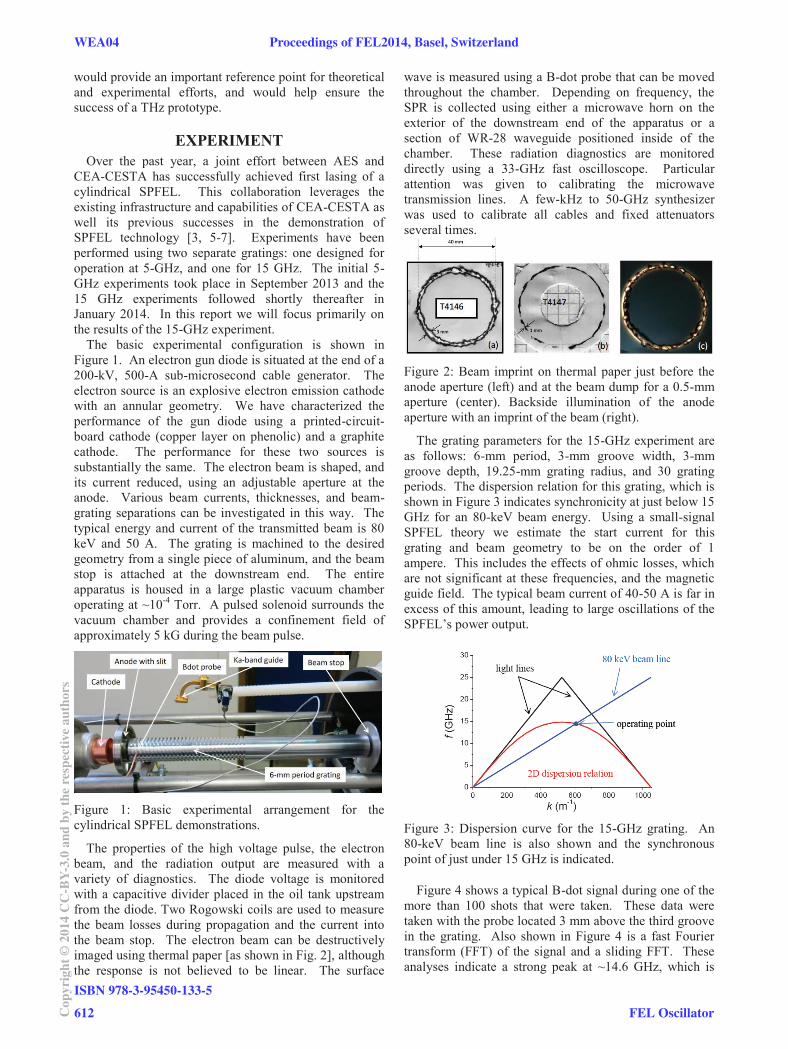
The properties of the high voltage pulse, the electron beam, and the radiation output are measured with a variety of diagnostics. The diode voltage is monitored with a capacitive divider placed in the oil tank upstream from the diode. Two Rogowski coils are used to measure the beam losses during propagation and the current into the beam stop. The electron beam can be destructively imaged using thermal paper [as shown in Fig. 2], although the response is not believed to be linear. The surface
wave is measured using a B-dot probe that can be moved throughout the chamber. Depending on frequency, the SPR is collected using either a microwave horn on the exterior of the downstream end of the apparatus or a section of WR-28 waveguide positioned inside of the chamber. These radiation diagnostics are monitored directly using a 33-GHz fast oscilloscope. Particular attention was given to calibrating the microwave transmission lines. A few-kHz to 50-GHz synthesizer was used to calibrate all cables and fixed attenuators several times.
Figure 2: Beam imprint on thermal paper just before the anode aperture (left) and at the beam dump for a 0.5-mm aperture (center). Backside illumination of the anode aperture with an imprint of the beam (right).
The grating parameters for the 15-GHz experiment are as follows: 6-mm period, 3-mm groove width, 3-mm groove depth, 19.25-mm grating radius, and 30 grating periods. The dispersion relation for this grating, which is shown in Figure 3 indicates synchronicity at just below 15 GHz for an 80-keV beam energy. Using a small-signal SPFEL theory we estimate the start current for this grating and beam geometry to be on the order of 1 ampere. This includes the effects of ohmic losses, which are not significant at these frequencies, and the magnetic guide field. The typical beam current of 40-50 A is far in excess of this amount, leading to large oscillations of the SPFEL’s power output.
Figure 3: Dispersion curve for the 15-GHz grating. An 80-keV beam line is also shown and the synchronous point of just under 15 GHz is indicated.
Figure 4 shows a typical B-dot signal during one of the more than 100 shots that were taken. These data were taken with the probe located 3 mm above the third groove in the grating. Also shown in Figure 4 is a fast Fourier transform (FFT) of the signal and a sliding FFT. These analyses indicate a strong peak at ~14.6 GHz, which is
WEA04 Proceedings of FEL2014, Basel, Switzerland
ISBN 978-3-95450-133-5
612Cop
yrig
ht©
2014
CC
-BY-
3.0
and
byth
ere
spec
tive
auth
ors
FEL Oscillator

very close to the expected frequency of the evanescent mode. The frequency of the mode changes slightly with time due to variation of the accelerating voltage in the electron gun. Based on the probe’s inductance and the calibration measurements of attenuation in the measurement system, we estimate a field strength of ~17 G at this location. The B-dot probe was subsequently placed at four different positions in azimuth to determine the homogeneity of the field strength; several shots were taken at each location. The field strength was nearly uniform in azimuth for this longitudinal position.
Figure 4: B-dot signal (top), FFT (center), and sliding FFT (bottom) for a typical shot.
The WR-28 waveguide used to collect the superradiant SPR is located ~65mm above the grating surface and can be positioned arbitrarily along the length of the grating. Conveniently, the length of the waveguide is sufficient to place the fundamental radiation beyond the cutoff frequency. A sliding FFT of a typical signal is shown in Figure 5. As expected, the signal is dominated by a single frequency (~29.2 GHz) that is exactly twice the fundamental. Again, the frequency variation is consistent with that expected from the time dependence of the beam
energy. The superradiant SPR was also found to be uniform in the azimuthal coordinate. Estimates of the emitted SPR power and comparisons with simulations are given in the following section.
Figure 5: Sliding FFT of the radiation collected by the WR-28 waveguide. The intensity map shows the FFT vs time, the black line is the nominal centroid of the distribution, the red line shows the variation of the beam voltage, and the green line is the theoretical operating frequency multiplied by two.
SIMULATIONS The simulations were carried out using two different
PIC codes: MAGIC 3D and VORPAL, and the agreement between these codes was found to be excellent. Figure 6 shows an intensity map of the azimuthal magnetic field during the lasing process and after saturation. The second harmonic is clearly visible in the top image at ~70° above the horizontal. Ultimately, for this simple grating, the radiation output is dominated by scattered fundamental radiation from the upstream end of the grating. Figure 7 shows the simulated azimuthal magnetic field at the nominal position of the B-dot probe. The observed frequency, 14.3 GHz, is very close to the 14.6 GHz measured in the experiments. Also, the field strength is of the same order, as seen in Table 1.
Proceedings of FEL2014, Basel, Switzerland WEA04
FEL Oscillator
ISBN 978-3-95450-133-5
613 Cop
yrig
ht©
2014
CC
-BY-
3.0
and
byth
ere
spec
tive
auth
ors

Figure 6: Intensity maps of the azimuthal magnetic field during lasing (top) and after saturation (bottom).
The collection efficiency of the WR-28 waveguide was determined using particle in cell (PIC) simulations in MAGIC 3D. The effective emitting area for the coherent SPR was estimated through simulations as well. Combining these simulated results with the experimental data, we estimate that the radiated power at 29 GHz is on the order of 8.5 kW. This compares well with the simulation estimates of ~5 kW. Although it was not measured in the experiments, the simulated third-harmonic power is ~0.5 kW.
Table 1: Comparison of Experimentally Estimated Field and Power Levels with Simulated Values from MAGIC and VORPAL
Figure 7: MAGIC (top) and VORPAL (bottom) simulations of the azimuthal magnetic field strength at the nominal location of the B-dot probe.
The simulated results can also be used to estimate the conversion efficiency between kinetic energy of the electron beam and energy in the fields. The energy loss
fluctuates wildly due to the excessively high beam current; however, the maximum rms kinetic energy lost by the beam is approximately 15 keV. This corresponds to a total power in the fields approaching a megawatt.
CONCLUSIONS AND FUTURE WORK AES has been developing a cylindrical Smith-Purcell
free-electron laser concept for the production of high-power THz radiation. Recently, a collaboration between AES and CEA-CESTA has successfully demonstrated first lasing of such a device at 5 and 15 GHz. Validation of key concepts in the microwave regime will help mitigate risk as system designs are pushed toward higher frequencies. Good agreement is obtained between experimental data, PIC simulations, and small-signal SPFEL theory. Building on these successes we are planning near-term demonstrations at 50 and 100 GHz (fundamental) using the same electron gun and power systems. Extensive simulations are being carried out to optimize grating structures according to various performance metrics, including start current, superradiant SPR production, and outcoupling efficiency for the evanescent fundamental. Additionally, AES is designing a 220-GHz prototype that will utilize existing cathode technology and a reliable, low-voltage, compressionless design.
ACKNOWLEDGMENT This work was supported by the Office of Naval
Research and the Office of Naval Research Global under contract No. N00014-10-C-0191 and grant No. N62909-13-1-N62.
REFERENCES [1] H. L. Andrews and C. A. Brau, Phys. Rev. ST Accel.
Beams 7, 070701 (2004). [2] S. J. Smith and E. M. Purcell, Phys. Rev. 92, 1069
(1953). [3] J. Gardelle, P. Modin, and J. T. Donohue, Appl.
Phys. Lett. 100, 131103 (2012). [4] H. L. Andrews, C. H. Boulware, C. A. Brau, and J.
D. Jarvis, Phys. Rev. ST Accel. Beams 8, 110702 (2005).
[5] J. Gardelle, L. Courtois, P. Modin, and J. T. Donohue, Phys. Rev. ST Accel. Beams 12, 110701 (2009).
[6] J. Gardelle, P. Modin, and J. T. Donohue, Phys. Rev. Lett. 105, 224801 (2010).
[7] J. T. Donohue and J. Gardelle, Appl. Phys. Lett. 99, 161112 (2011).
WEA04 Proceedings of FEL2014, Basel, Switzerland
ISBN 978-3-95450-133-5
614Cop
yrig
ht©
2014
CC
-BY-
3.0
and
byth
ere
spec
tive
auth
ors
FEL Oscillator