first season quiet observations: measurements of …
TRANSCRIPT

The Astrophysical Journal, 741:111 (18pp), 2011 November 10 doi:10.1088/0004-637X/741/2/111C© 2011. The American Astronomical Society. All rights reserved. Printed in the U.S.A.
FIRST SEASON QUIET OBSERVATIONS: MEASUREMENTS OF COSMIC MICROWAVE BACKGROUNDPOLARIZATION POWER SPECTRA AT 43 GHz IN THE MULTIPOLE RANGE 25 ! ! ! 475
QUIET Collaboration, C. Bischoff1,22, A. Brizius1,2, I. Buder1, Y. Chinone3,4, K. Cleary5, R. N. Dumoulin6,A. Kusaka1, R. Monsalve7, S. K. Næss8, L. B. Newburgh6,23, R. Reeves5, K. M. Smith1,23, I. K. Wehus9, J. A. Zuntz10,11,12,
J. T. L. Zwart6, L. Bronfman13, R. Bustos7,13,14, S. E. Church15, C. Dickinson16, H. K. Eriksen8,17, P. G. Ferreira10,T. Gaier18, J. O. Gundersen7, M. Hasegawa3, M. Hazumi3, K. M. Huffenberger7, M. E. Jones10, P. Kangaslahti18,
D. J. Kapner1,24, C. R. Lawrence18, M. Limon6, J. May13, J. J. McMahon19, A. D. Miller6, H. Nguyen20, G. W. Nixon21,T. J. Pearson5, L. Piccirillo16, S. J. E. Radford5, A. C. S. Readhead5, J. L. Richards5, D. Samtleben2,25, M. Seiffert18,
M. C. Shepherd5, S. T. Staggs21, O. Tajima1,3, K. L. Thompson15, K. Vanderlinde1,26, R. Williamson6,27, and B. Winstein11 Kavli Institute for Cosmological Physics, Department of Physics, Enrico Fermi Institute, The University of Chicago,
Chicago, IL 60637, USA; [email protected] Max-Planck-Institut fur Radioastronomie, 53121 Bonn, Germany
3 High Energy Accelerator Research Organization (KEK), Tsukuba, Ibaraki 305-0801, Japan4 Astronomical Institute, Graduate School of Science, Tohoku University, Aramaki, Aoba, Sendai 980-8578, Japan
5 Cahill Center for Astronomy and Astrophysics, California Institute of Technology, Pasadena, CA 91125, USA6 Department of Physics and Columbia Astrophysics Laboratory, Columbia University, New York, NY 10027, USA
7 Department of Physics, University of Miami, Coral Gables, FL 33146, USA8 Institute of Theoretical Astrophysics, University of Oslo, N-0315 Oslo, Norway
9 Department of Physics, University of Oslo, N-0316 Oslo, Norway10 Department of Astrophysics, University of Oxford, Oxford OX1 3RH, UK
11 Oxford Martin School, Oxford OX1 3BD, UK12 Department of Physics and Astronomy, University College London, London WC1E, UK
13 Departamento de Astronomıa, Universidad de Chile, Casilla 36-D, Santiago, Chile14 Departamento de Astronomıa, Universidad de Concepcion, Casilla 160-C, Concepcion, Chile
15 Kavli Institute for Particle Astrophysics and Cosmology and Department of Physics, Stanford University,Varian Physics Building, Stanford, CA 94305, USA
16 Jodrell Bank Centre for Astrophysics, Alan Turing Building, School of Physics and Astronomy,The University of Manchester, Manchester M13 9PL, UK
17 Centre of Mathematics for Applications, University of Oslo, N-0316 Oslo, Norway18 Jet Propulsion Laboratory, California Institute of Technology, Pasadena, CA 91109, USA
19 Department of Physics, University of Michigan, Ann Arbor, MI 48109, USA20 Fermi National Accelerator Laboratory, Batavia, IL 60510, USA
21 Joseph Henry Laboratories of Physics, Jadwin Hall, Princeton University, Princeton, NJ 08544, USAReceived 2010 December 14; accepted 2011 July 12; published 2011 October 25
ABSTRACT
The Q/U Imaging ExperimenT (QUIET) employs coherent receivers at 43 GHz and 94 GHz, operating on theChajnantor plateau in the Atacama Desert in Chile, to measure the anisotropy in the polarization of the cosmicmicrowave background (CMB). QUIET primarily targets the B modes from primordial gravitational waves. Thecombination of these frequencies gives sensitivity to foreground contributions from diffuse Galactic synchrotronradiation. Between 2008 October and 2010 December, over 10,000 hr of data were collected, first with the19 element 43 GHz array (3458 hr) and then with the 90 element 94 GHz array. Each array observes the samefour fields, selected for low foregrounds, together covering ≈1000 deg2. This paper reports initial results from the43 GHz receiver, which has an array sensitivity to CMB fluctuations of 69 µK
√s. The data were extensively studied
with a large suite of null tests before the power spectra, determined with two independent pipelines, were examined.Analysis choices, including data selection, were modified until the null tests passed. Cross-correlating maps withdifferent telescope pointings is used to eliminate a bias. This paper reports the EE, BB, and EB power spectra inthe multipole range ! = 25–475. With the exception of the lowest multipole bin for one of the fields, where apolarized foreground, consistent with Galactic synchrotron radiation, is detected with 3σ significance, the E-modespectrum is consistent with the ΛCDM model, confirming the only previous detection of the first acoustic peak. TheB-mode spectrum is consistent with zero, leading to a measurement of the tensor-to-scalar ratio of r = 0.35+1.06
−0.87.The combination of a new time-stream “double-demodulation” technique, side-fed Dragonian optics, natural skyrotation, and frequent boresight rotation leads to the lowest level of systematic contamination in the B-mode powerso far reported, below the level of r = 0.1.
Key words: cosmic background radiation – cosmology: observations – gravitational waves – inflation –polarization
Online-only material: color figures, extended figure
22 Current address: Harvard-Smithsonian Center for Astrophysics, 60 GardenStreet MS 43, Cambridge, MA 02138, USA.23 Current address: Joseph Henry Laboratories of Physics, Jadwin Hall,Princeton University, Princeton, NJ 08544, USA.24 Current address: Micro Encoder Inc., Kirkland, WA 98034, USA.
25 Current address: Nikhef, Science Park, Amsterdam, The Netherlands.26 Current address: Department of Physics, McGill University, 3600 RueUniversity, Montreal, Quebec H3A 2T8, Canada.27 Current address: Kavli Institute for Cosmological Physics, Enrico FermiInstitute, The University of Chicago, Chicago, IL 60637, USA.
1

The Astrophysical Journal, 741:111 (18pp), 2011 November 10 QUIET Collaboration et al.
1. INTRODUCTION
The inflationary paradigm resolves several outstanding issuesin cosmology, including the flatness, horizon, and monopoleproblems, and it provides a compelling explanation for theorigin of structure in the universe (e.g., Liddle & Lyth 2000and references therein). So far all cosmological data, includ-ing measurements of cosmic microwave background (CMB)anisotropies, support this paradigm; still, the underlying funda-mental physics responsible for inflation is unknown. Inflationproduces a stochastic background of gravity waves that induceodd-parity tensor “B modes” at large angular scales in the CMBpolarization. If these primordial B modes, parameterized by thetensor-to-scalar ratio r, are detected, one can learn about the en-ergy scale of inflation. In many attractive slow-roll models, thisscale is given approximately by r1/4 × 1016 GeV. For large-fieldmodels, the energy scale is near the Grand Unification Scale inparticle physics, so that r " 0.01. A new generation of experi-ments aims for good sensitivity in this range of r. Establishingthe existence of primordial B modes would both verify an im-portant prediction of inflation and provide access to physics atan incredibly high energy scale.
The most stringent limit to date is r < 0.20 at the 95%confidence level (Komatsu et al. 2011) set by a combination ofCMB-temperature-anisotropy measurements, baryon acousticoscillations, and supernova observations, but cosmic varianceprohibits improvements using only these measurements.
E-mode polarization has now been detected by many exper-iments (e.g., Kovac et al. 2002; Leitch et al. 2005; Montroyet al. 2006; Sievers et al. 2007; Wu et al. 2007; Bischoff et al.2008; Larson et al. 2011). These measurements are consistentwith predictions from CMB-temperature-anisotropy measure-ments, and they provide new information on the epoch ofreionization. Only BICEP has accurately measured E-modepolarization in the region of the first acoustic peak (Chianget al. 2010); that paper also reports the best limit on r comingfrom cosmological B modes: r < 0.72 at the 95% confidencelevel.
Experiments measuring B-mode polarization in the CMBshould yield the best information on r, but this technique isstill in its infancy. B modes are expected to be at least an orderof magnitude smaller than the E modes so control of system-atic errors and foregrounds will be particularly critical. Below≈90 GHz, the dominant foreground comes from Galactic syn-chrotron emission, while at higher frequencies, emission fromthermal dust dominates. Most planned or operating CMB po-larization experiments employ bolometric detectors observingmost comfortably at frequencies "90 GHz, so they cannot esti-mate synchrotron contamination from their own data.
The Q/U Imaging ExperimenT (QUIET) is one of two CMBpolarization experiments to observe at frequencies suitable foraddressing synchrotron contamination, making observations at43 GHz (Q band) and 94 GHz (W band) and with sufficientsensitivity to begin to probe primordial B modes. The other isPlanck (Tauber et al. 2010).
QUIET uses compact polarization-sensitive modules basedupon High Electron Mobility Transistor (HEMT) amplifiers,combined with a new time-stream “double-demodulation” tech-nique, side-fed Dragonian optics (for the first time in a CMBpolarization experiment), natural sky rotation, and frequent ro-tation about the optical axis to achieve a very low level of con-tamination in the multipole range where a primordial-B-modesignal is expected.
Figure 1. Overview of the QUIET instrument. The cryostat and 1.4 m telescopemirrors are enclosed in a rectangular comoving absorbing ground screen; inthis figure its walls are transparent. The telescope, cryostat, and electronicsare mounted on a single platform attached to the deck bearing, which allowsrotations around the instrument’s optical axis.(A color version of this figure is available in the online journal.)
Between 2008 October and 2010 December, QUIET collectedover 10,000 hr of data, split between the Q-band and W-bandreceivers. Here, we report first results from the first season of3458 hr of Q-band observation. The principal investigator forQUIET was our recently deceased colleague, Bruce Winstein,whose intellectual and scientific guidance was crucial to QUIETin all of its stages, from design through analysis, through thewriting of this paper.
After describing the instrument, observations, and detectorcalibrations (Sections 2–4), we discuss our analysis techniquesand consistency checks (Sections 5 and 6). CMB power spec-tra are then presented together with a foreground detection(Section 7). We evaluate our systematic errors (Section 8) andthen conclude (Section 9).
2. THE INSTRUMENT
The QUIET instrument comprises an array of correlationpolarimeters cooled to 20 K and coupled to a dual-reflectortelescope, installed on a three-axis mount inside a comovingground screen. The instrument is illustrated in Figure 1. Furtherdetails are given below and in Newburgh (2010), Kusaka (2010),and Buder (2010).
The Q-band QUIET receiver is a 19 element array containing17 low-noise correlation polarimeters, each simultaneouslymeasuring the Stokes Q, U, and I parameters, and two CMBdifferential-temperature monitors.
QUIET uses a 1.4 m classical side-fed Dragonian antenna(Dragone 1978). This consists of a parabolic primary, a concavehyperbolic secondary along with a platelet array of corrugatedfeed horns (Gundersen & Wollack 2009). These elements areoriented in a way to satisfy the Mizuguchi condition (Mizugutchet al. 1976) in order to minimize cross polar response, andunlike dual offset classical Gregorian or Cassegrain antennas,the elements combine to generate high gain with low sideloberesponse over a wide field of view (Chang & Prata 2004). Thetelescope is described in detail in Imbriale et al. (2011). It yieldsan FWHM beam size of 27.′3 and a roughly circular field ofview of 7◦ in diameter. Radiation from each feed horn enters aseptum polarizer (Bornemann & Labay 1995) which separatesleft and right circularly polarized components (L and R) into
2

The Astrophysical Journal, 741:111 (18pp), 2011 November 10 QUIET Collaboration et al.
two waveguide ports that mate to a QUIET correlation module,detailed below.
The module array and feed horns are cooled to 20 K in acryostat to reduce instrumental noise. An electronics enclosuremounted next to the cryostat houses the electronics necessaryfor biasing the modules and recording their data. The cryostat,electronics, and telescope are installed on the former CosmicBackground Imager mount (Padin et al. 2002). This mountprovides three-axis motion: azimuth, elevation, and rotationabout the optical axis. This last is called “deck” rotation.
The cryostat and telescope are enclosed by an absorbingcomoving ground screen. The ground screen was designed tohave two parts, but the upper section (not shown in Figure 1) wasnot installed until after the Q-band instrument was removed. Itsabsence was correctly anticipated to result in two far sidelobes,which were mapped with a high-power source by the QUIETW-band instrument in the field and measured to be #–60 dB withthe QUIET Q-band instrument when the Sun passed throughthem. The effects of these sidelobes are mitigated throughfiltering and data selection (Sections 5.1.3 and 5.2). Section 8.4shows that any residual contamination is small.
Each QUIET Q-band correlation module, in a footprint ofonly 5.1 × 5.1 cm2, receives the circular polarization modes ofthe celestial radiation and outputs Stokes Q, U, and I as follows.Each input is independently amplified and passed through aphase switch. One phase switch alternates the sign of the signalvoltage at 4 kHz, while the other switches do so at 50 Hz. Thetwo signals are combined in a 180◦ hybrid coupler, with outputsproportional to the sum and difference of the inputs. Since themodule inputs are proportional to (L,R) = (Ex ± iEy)/
√2,
where Ex and Ey are orthogonal components of the incidentelectric field, the coupler outputs are amplified versions of Exand iEy, with the phase switch reversing their roles. Half of eachoutput is bandpass filtered and rectified by a pair of detectordiodes, while the other half passes into a 90◦ hybrid coupler. Asecond pair of bandpass filters and detector diodes measures thepower from this coupler’s outputs (Kangaslahti et al. 2006).
Synchronous demodulation of the 4 kHz phase switchingyields measurements of Stokes +Q and −Q on the first twodiodes and Stokes +U and −U on the remaining two. This high-frequency differencing suppresses low-frequency atmosphericfluctuations as well as 1/f noise from the amplifiers, detectordiodes, bias electronics, and data-acquisition electronics. Sub-sequent demodulation of the 50 Hz phase switching removesspurious instrumental polarization generated by unequal trans-mission coefficients in the phase-switch circuits. The resultingfour “double-demodulated” time streams are the polarizationchannels.
Averaging the output of each diode rather than demodulatingit results in a measurement of Stokes I, hereafter called totalpower, denoted “TP.” The TP time streams are useful for moni-toring the weather and the stability of the detector responsivities,but suffer too much contamination from 1/f noise to constrainthe CMB temperature anisotropy. Therefore, the Q-band instru-ment includes two correlation modules that are coupled to apair of neighboring feed horns to measure the temperature dif-ference between them, in a scheme similar to the WilkinsonMicrowave Anisotropy Probe (WMAP) differencing assemblies(Jarosik et al. 2003). These differential-temperature modulesprovide calibration data for the telescope pointing, beams, andsidelobes, as well as CMB data. Their feed horns are in theouter ring of the close-packed hexagonal array, ≈3◦ from thecenter.
Table 1Patch Locations and Integration Times
Patch R.A. Decl. Integration(J2000) Hours
CMB-1 12h04m −39◦00′ 905CMB-2 05h12m −39◦00′ 703CMB-3 00h48m −48◦00′ 837CMB-4 22h44m −36◦00′ 223
G-1 16h00m −53◦00′ 311G-2 17h46m −28◦56′ 92
Notes. The central equatorial coordinates and integration times for eachobserving patch. G-1 and G-2 are Galactic patches.
Here, we summarize several array-wide characteristics of thepolarimeters. Bandpass measurements in the lab and at the startof the observing season find that the average center frequencyis 43.1±0.4 GHz, and the average bandwidth is 7.6±0.5 GHz.We calculate the noise power spectra of the double-demodulatedpolarimeter time streams from each 40–90 minute observationto assess their 1/f knee frequencies and white-noise levels (seeSection 5.1). The median 1/f knee frequency is 5.5 mHz, wellbelow the telescope scan frequencies of 45–100 mHz.
From the white-noise levels and responsivities (Section 4.1),we find an array sensitivity28 to CMB fluctuations of 69 µK
√s,
such that the mean polarized sensitivity per module is280 µK
√s.
3. OBSERVATIONS
QUIET is located on the Chajnantor plateau in the AtacamaDesert of northern Chile (67◦45′42′′W, 23◦01′42′′S). A combi-nation of high altitude (5080 m) and extreme dryness results inexcellent observing conditions for most of the year. During theeight months of QUIET Q-band observations, the median pre-cipitable water vapor (PWV) measured at the nearby AtacamaPathfinder Experiment site (Gusten et al. 2006) was 1.2 mm.
We began observations with the Q-band receiver on 2008October 24, and took 3458 hr of data until 2009 June 13 (whenthe receiver was replaced on the telescope by the 90 elementW-band receiver). Of these data, 77% are for CMB, with 12%of the observing time used for Galactic fields, 7% for calibrationsources, and 4% cut due to obvious instrumental problems suchas lack of telescope motion. We observe 24 hr a day, exceptwhen interrupted. Our full-season operating efficiency is 63%;causes of downtime include occasional snow, power outages,and mechanical failures.
3.1. Field Selection
We observe four CMB fields, referred to henceforth as“patches.” Table 1 lists their center positions and total integrationtimes, while Figure 2 indicates their positions on the sky.29
The number of patches is determined by the requirement toalways have one patch above the lower elevation limit of themount (43◦). The specific positions of each patch were chosento minimize foreground emission using WMAP three-year data.The area of each patch is ≈250 deg2. In addition to the four
28 This is the sensitivity for 62 polarization channels. Six of 68 polarizationchannels are non-functional—an array yield of 92%.29 Patch CMB-3 partially overlaps with the field the BICEP collaboration hasobserved for CMB analysis (Chiang et al. 2010). The data may be used forfuture analysis cross-correlating maps from the two experiments.
3

The Astrophysical Journal, 741:111 (18pp), 2011 November 10 QUIET Collaboration et al.
CMB-1
G-1
G-2
CMB-2
CMB-4
CMB-3
20 mK
20h
18h
16h
14h
12h
22h0h2h4h6h8h
60°
30°
0°
-30°
-60°
Figure 2. CMB and Galactic patches, in equatorial coordinates, superimposedon a Q-band all-sky WMAP seven-year temperature map (Jarosik et al. 2010).Note that the Galactic-plane temperature signal saturates the color scale. PatchG-2 is the Galactic center.(A color version of this figure is available in the online journal.)
CMB patches, we observe two Galactic patches. These allowus to constrain the spectral properties of the polarized low-frequency foregrounds with a high-signal-to-noise ratio. Theresults from the Galactic observations will be presented in afuture publication.
3.2. Observing Strategy
Scanning the telescope modulates the signal from the sky,converting CMB angular scales into frequencies in the polarime-ter time streams. Since QUIET targets large angular scales, fastscanning (≈5◦ s−1 in azimuth) is critical to ensure that the po-larization modes of interest appear at higher frequencies thanthe atmospheric and instrumental 1/f knee frequencies.
So that each module sees a roughly constant atmosphericsignal, QUIET scans are periodic motions solely in azimuthwith both the elevation and deck-rotation axes fixed. Each scanhas an amplitude of 7.◦5 on the sky, with period 10–22 s. Theseazimuth scans are repeated for 40–90 minutes; each set of scansat fixed elevation is denoted a “constant-elevation scan” (CES).We repoint the telescope and begin a new CES when the patchcenter has moved by 15◦ in order to build up data over an area of≈15◦ ×15◦ for each patch. Note that a central region (8◦ acrossis observed by all polarimeters since the instrument’s field ofview has a diameter of (7◦. Diurnal sky rotation and weeklydeck rotations provide uniform parallactic-angle coverage of thepatch, and ensure that its peripheral regions are also observedby multiple polarimeters.
4. CALIBRATION
Four quantities are required to convert polarimeter timestreams into polarization power spectra: detector responsivi-ties, a pointing model, detector polarization angles, and beamprofiles. To this end, a suite of calibration observations is per-formed throughout the season using astronomical sources (Tau-rus A—hereafter Tau A, Jupiter, Venus, RCW38, and the Moon),atmospheric measurements (“sky dips,” which typically con-sist of three elevation nods of ±3◦), and instrumental sources(a rotating sparse wire grid and a polarized broadband noisesource). From these we also measure instrumental polarization,as described below. QUIET’s regular calibration observationsare summarized in Table 2.
We typically use two or more methods to determine acalibration constant, taking the spread among the methods as
-20-10
01020
-20-10
01020
-20-10
01020
Instrument Position Angle (deg)-20 0 20 40 60 80 100 120 140 160
-20-10
01020
V)
µR
espo
nse
to P
olar
izat
ion
of T
auA
(
Q
-Q
U
-U
Figure 3. Polarimeter responses from the central feed horn to the polarization ofTau A at four deck angles. The horizontal axis corresponds to the position angleof the receiver focal plane in equatorial coordinates. These data were collectedwith one correlation module in about 20 minutes. The errors are smaller thanthe points. From top to bottom, responses are shown for the detector diodessensitive to the Stokes parameters + Q, −Q, + U, and −U, respectively. Foreach, the fitted model is plotted as a dashed line.
Table 2Regular Calibration Observations
Source Schedule Duration(minutes)
Sky dips Every 1.5 hr 3Tau A Every 1–2 days 20Moon Weekly 60Jupiter Weekly 20Venus Weekly 20RCW38 Weekly 20
an indication of the uncertainty. We show in Section 8 thataside from the case of absolute responsivity, all calibrationuncertainties lead to estimates of systematic effects on the powerspectra well below statistical errors. This immunity comes fromhaving a large number of detectors and highly cross-linkedpolarization maps.
4.1. Responsivity
The polarized flux from Tau A provides a 5 mK signal whichwe observe at four parallactic angles. The sinusoidal modulationof the signal induced by the changing parallactic angles is fittedto yield responsivity coefficients for each detector. Figure 3shows the response of the four polarization channels from thecentral feed horn to Tau A. A typical responsivity is 2.3 mV K−1,with a precision from a single set of observations of 6%. Theabsolute responsivity from Tau A was measured most frequentlyfor the central feed horn. We choose its +Q diode detector toprovide the fiducial absolute responsivity.
The responsivities of other detectors relative to the fiducialdetector are determined with the sky dips as described below.We have three independent means of assessing the relativeresponsivities among polarimeters: from nearly simultaneousmeasurements of the Moon, from simultaneous measurementsof responses to the rotating sparse wire grid in post-season tests,
4

The Astrophysical Journal, 741:111 (18pp), 2011 November 10 QUIET Collaboration et al.
and from Tau A measurements. The errors from these methodsare 4%, 2%, and 6%, respectively, while the error from thesky-dip method is 4%. All the methods agree within errors.
Sky dips generate temperature signals of several 100 mK andthus permit measurement of the TP responsivities. The signalsvary slightly with PWV. We estimate the slope from the data as4% mm−1 and correct for it. This slope is consistent with theatmospheric model of Pardo et al. (2001). Because the ratiosof the responsivities for the TP and polarized signals from eachdetector diode are stable quantities within a few percent of unity,we use sky dips performed immediately before each CES tocorrect short-term variations in the polarimeter responsivities.The responsivities vary by #10% over the course of a daydue to changing thermal conditions for the bias electronics.Further post-season tests provide a physical model: the relevanttemperatures are varied intentionally while the responsivitiesare measured with sky dips. We confirm the results with thepolarized broadband source.
We bound the uncertainty in the absolute responsivity ofthe polarimeter array at 6%. The largest contributions to thisestimate are uncertainties in (1) the beam solid angle (4%, seebelow), (2) the response difference between polarized and TPsignals for each diode detector (3%), and (3) the Tau A flux (3%;Weiland et al. 2011). The first enters in converting the flux ofTau A into µK, while the second enters because, although onefiducial diode detector is calibrated directly from Tau A, for therest we find relative responsivities from sky dips and normalizeby the fiducial diode’s responsivity.
For the differential-temperature modules, all detectors ob-serve the signal from Jupiter simultaneously, providing the ab-solute responsivity for all channels upon comparison with theJupiter flux from Weiland et al. (2011). Observations of Venus(Hafez et al. 2008) and RCW38 agree with the Jupiter measure-ments within errors, and sky dips track short-term variations.We calibrate the absolute responsivity with 5% accuracy.
4.2. Pointing
The global pointing solution derives from a physical modelof the three-axis mount and telescope tied to observations of theMoon with the central feed horn in the array, as well as Jupiterand Venus with the differential-temperature feed horns. Opticalobservations are taken regularly with a co-aligned star cameraand used to monitor the time evolution of the pointing model.
During the first two months in the season, a mechanical prob-lem with the deck-angle encoder resulted in pointing shifts. Theproblem was subsequently repaired. Based on pointing observa-tions of the Moon and other astronomical sources, we verify thatthese encoder shifts are less than 2◦. Systematic uncertaintiesinduced by this problem are discussed in Section 8.1.
After the deck-angle problem is fixed, no significant evolutionof the pointing model is found. The difference in the meanpointing solution between the start and the end of the seasonis smaller than 1′. Observations of the Moon and Jupiter alsoprovide the relative pointing among the feed horns. The rmspointing error in the maps is 3.′5.
4.3. Detector Polarization Angles
Our primary measurement of the polarization angle foreach detector comes from observing the radial polarizationof the Moon, as illustrated in Figure 4. The measurementhas a high signal-to-noise ratio and its inaccuracy is domi-nated by systematic error due to the temperature gradient of
-1 -0.5 0 0.5 1x [degrees]
-1
-0.5
0
0.5
1
y [d
egre
es]
Figure 4. Map of the polarization of the Moon from one detector diode. Theamplitude of the quadrupole polarization visible here is ≈400 mK. Similar mapsare produced for all 17 polarization modules in the array with a single ≈ hour-long observation. The dotted line indicates the polarization orientation of thedetector. Contours are spaced at intervals of 100 mK, with negative contoursindicated by dashed lines.
the Moon surface. One can see the effect in the different am-plitudes of the two positive envelopes in Figure 4. The fluc-tuations of the detector polarization-angle measurements overmany observations with different phases of the Moon and tele-scope orientations are typically 1◦ in rms. Although simulationssuggest these fluctuations can be due to the failure to account inanalysis for the temperature gradient, we conservatively assignthem as upper limits on the fluctuations of the polarization anglesduring the season. Based on this conservative limit, we estimatethe systematic error in the CMB-power-spectra measurement inSection 8.2, resulting in a negligible contribution.
Two other less precise methods also give estimates of thedetector angles: fits to the Tau A data, and the determinationof the phases of the sinusoidal responses of all the detectors torotation of the sparse wire grid. In each case, the differencesbetween the detector angles determined by the secondarymethod and the Moon are described by a standard deviationof ≈3◦. However, we find a mean shift between the Tau Aderived and Moon-derived angles of 1.◦7. To estimate the errorsin the angles in light of this shift, we use an empirical approach:in Section 8.2 we estimate the impact on the power spectra fromusing the Tau A results instead of the Moon results, and find itto be small.
4.4. Beam Profile and Window Function
The polarization and differential-temperature beams are ob-tained from maps created using the full data sets of Tau A andJupiter observations, respectively, with square pixels of 1.′8 on aside. For polarization, this process produces the main and leak-age beam maps simultaneously, with the latter describing theinstrumental polarization. The average FWHM for the beamsacross the array is 27.′3, measured with 0.′1 precision for thecentral feed horn and for the differential-temperature feed hornsat the edge of the focal plane. The non-central–polarization-horn FWHMs are measured less frequently and thus are lessprecisely known, with an uncertainty of 1.′5. The beam elon-gation is typically small (1%), and its effect is further reducedby the diurnal sky rotation and weekly deck rotations whichresult in a symmetrized effective beam in the CMB maps. Wecompute one-dimensional symmetrized beam profiles, with a
5

The Astrophysical Journal, 741:111 (18pp), 2011 November 10 QUIET Collaboration et al.
10-3
10-2
10-1
100
0 10 20 30 40 50
Nor
mal
ized
Bea
m P
rofil
e
Angle from Beam Center [arcmin]
MeasurementModel
10-2
10-1
100
0 100 200 300 400 500
Bea
m W
indo
w F
unct
ion
Figure 5. Top panel: polarization beam profile from Tau A observations with thecentral feed horn. The data are overplotted with the expansion in Gauss–Hermitepolynomials described in the text. Bottom panel: beam window function witherrors shown by the gray band.
resolution of 0.′6. These profiles are modeled as a sum of sixeven Gauss–Hermite terms (Monsalve 2010). The main-beamsolid angles are computed by integrating these models out to 54′
(roughly −28 dB), yielding 78.0 ± 0.4 µsr for the differential-temperature horns and 74.3 ± 0.7 µsr for the central horn. Anaverage gives 76 µsr for all horns in the array. We also exam-ine alternative estimates such as integrating the raw beam mapinstead of the analytical fit. We assign a systematic uncertaintyof 4% based on the differences among these different estimates.The systematic error includes possible contributions from side-lobes, which we constrain to 0.7 ± 0.4 µsr with antenna rangemeasurements carried out before the observation season.
The window functions, encoding the effect of the finiteresolution of the instrument on the power spectra, are computedfrom the central-horn and the temperature-horn–profile models.The central-horn beam profile and window function are shownin Figure 5. The uncertainty accounts for statistical error anddifferences between polarization and differential-temperaturebeams, as described in Section 8.1.
4.5. Instrumental Polarization
Instrumental imperfections can lead to a spurious polariza-tion signal proportional to the unpolarized CMB temperatureanisotropy. We call this the I to Q (or U) leakage term. In ourinstrument, a fraction of the power input on one port of the cor-relation module is reflected because of a bandpass mismatch tothe septum polarizer, and a fraction of the reflected power re-enters the other port. The dominant monopole term comes fromthis effect. We measure the monopole term from the polarimeterresponses to temperature changes, using sky dips; Moon, TauA, and Galactic signals; as well as variations from the weather.The average magnitude is 1.0% (0.2%) for the Q (U) diodes.Note that the discrepancy in the Q and U averages was predictedfrom measurements of the properties of the septum polarizers
and confirmed in the field. We do not correct for this effect butassign systematic errors as described in Section 8.3.
5. DATA ANALYSIS PROCEDURE
QUIET employs two independent analysis pipelines to deriveCMB power spectra. We present the methods used for analysisin each pipeline, including data selection, filtering, map making,and power-spectra estimation.
Pipeline A is based on the pseudo-C! analysis framework, firstdescribed by Hivon et al. (2002), which is used by numerousexperiments (Netterfield et al. 2002; Brown et al. 2009; Chianget al. 2010; Larson et al. 2011; Lueker et al. 2010). This pipelinemade all analysis choices in accordance with a strict (blind)analysis validation policy described in Section 6. An advantageof the pseudo-C! framework is computational efficiency, whichis critical for completing the more than 30 iterations of thenull-test suite. For the same reason, this pipeline is used forthe systematic-error evaluations found in Section 8. Pseudo-C!
analysis also enables us to perform cross-correlation, makingthe resultant power spectra immune to possible misestimationof noise bias.
Pipeline B implements a maximum-likelihood framework(e.g., Tegmark 1997; Bond et al. 1998), which has a longhistory of use by CMB experiments (e.g., Mauskopf et al.2000; Page et al. 2007; Wu et al. 2007; Bischoff et al. 2008).This framework yields minimum-variance estimates of thepower spectra, naturally accounts for E/B mixing, and directlyprovides the exact CMB likelihood required for estimationof cosmological parameters, without the use of analyticalapproximations. In addition to power spectra, it producesunbiased maps with full noise-covariance matrices, useful forcomparisons with other experiments. On the other hand, thisapproach is also computationally more expensive than thepseudo-C! framework, and a reduced set of null tests is thereforeused to evaluate data consistency.
The processing of the time-ordered data (TOD) and themethodology used for data selection are treated in Sections 5.1and 5.2, respectively. Brief descriptions of the pseudo-C!
and maximum-likelihood techniques are found in Section 5.3.TOD processing, data selection, and analysis for temperature-sensitive modules are discussed in Section 5.4.
5.1. Time-ordered-data Processing
To prepare the TOD for map making, we execute three steps:pre-processing, noise modeling, and filtering. Of these steps,only the filtering is significantly different between the twopipelines.
5.1.1. Pre-processing
The first data-processing step is to correct for a smallnonlinearity that was discovered in the analog-to-digital con-verter (ADC) system. The nonlinearities occur every 1024 bits;roughly 14% of the data are affected. Systematic uncertaintyfrom this effect is estimated in Section 8.5. Next, the receiverdata are synchronized with the telescope pointing. The double-demodulation step, described in Section 2, is applied, reducingthe sample rate from 100 Hz to 50 Hz. A model of the de-tectors’ polarized responsivities converts the data from ADCcounts into thermodynamic temperature. The two pipelines usedifferent responsivity models. Pipeline A applies a constant re-sponsivity throughout each CES, addressing possible variabilitywithin a CES as part of the systematic error (Section 8); pipeline
6

The Astrophysical Journal, 741:111 (18pp), 2011 November 10 QUIET Collaboration et al.
B updates responsivities on two-minute timescales (Dumoulin2010).
5.1.2. Noise Model
After pre-processing, the time streams for each detector diodein each CES are Fourier-transformed and their noise powerspectra are fit to a model30 with three parameters: the amplitudeof white noise, the 1/f knee frequency, and the power-law slopeof the 1/f noise. We also compute the white-noise correlationsamong detector diodes in the same module: the most importantare between the two Q or the two U detector diodes (withan average coefficient of 0.22). A small fraction of the noisespectra contain features not accounted for in the noise model:beam sidelobes (see Section 2) scanning across features on theground create a narrow spike at the scan frequency; slowlychanging weather patterns during a CES create a broader peakalso at the scan frequency; and there are some narrow spikesat high ("6 Hz) frequencies. To prevent these features frombiasing the noise model, the fit excludes a region around thescan frequency as well as frequencies above 4.6 Hz. In additionto the noise-model parameters, several statistics quantifying theagreement between the data and noise model are also used fordata selection as described in Section 5.2.
5.1.3. Filtering
In pipeline A, three filters are applied. These were cho-sen from the results of many runs of the null-test suite(see Section 6). First, to remove the high-frequency narrowspikes, we apply a low-pass filter that cuts signals off sharplyabove 4.6 Hz.31 Second, to suppress contamination from atmo-spheric fluctuations and detector 1/f noise, we subtract a lin-ear function from each telescope half-scan (left-going or right-going) removing modes below twice the scan frequency.32 Thethird filter, designed to eliminate signal from ground emission,removes any azimuthal structure that remains after summingover all half-scans in the CES.
In pipeline B, an apodized bandpass filter is used thataccepts modes from 2.5 times the scan frequency to 4.5 Hz;the high-pass component of this filter is designed to suppressscan-synchronous contamination. Further, a time-independentground-emission model is subtracted. The model of groundemission is generated by building low-resolution and high-signal-to-noise maps in horizon coordinates from the full-seasondata for each deck angle and module, using large (55′) pixels.Only features that are stable in time, azimuth, elevation, anddeck angle contribute to this model. The amplitude of the groundcorrection is #1 µK.
5.2. Data Selection
The fundamental unit of data used for analysis is the double-demodulated output of one detector diode for a single CES,referred to as a “CES-diode.” Selecting only those CES-diodesthat correspond to good detector performance and observingconditions is a critical aspect of the data analysis. The data-selection criteria began with a nominal set of cuts and evolvedinto several distinct configurations, as many as 33 in the caseof pipeline A. For each configuration, analysis validation (see
30 At the level of a single CES, the TOD of each detector diode are dominatedby noise; the contribution of the CMB is negligible.31 For QUIET’s beam size and scanning speed a low-pass filter of 4.5–4.6 Hzresults in a minimal loss of sensitivity to the CMB.32 Typical scan frequencies range from 45 mHz to 100 mHz.
Table 3Total Hours Observed and Data-selection Efficiencies
Patch Total Hours A B Common(%) (%) (%)
CMB-1 905 81.7 84.3 76.7CMB-2 703 67.3 70.0 61.2CMB-3 837 56.0 61.4 51.4CMB-4 223 70.6 74.2 65.9
All patches 2668 69.4 72.9 64.2
Notes. Selection efficiencies for each pipeline. “Common” gives the efficienciesif both sets of cuts were applied.
Section 6) was performed yielding statistics quantifying the lackof contamination in the data set. The final data set was chosenwhen these statistics showed negligible contamination and werelittle affected by changes to the cuts.
Cut efficiencies, defined as the fractions of CES-diodesaccepted for the analysis, are given for both pipelines in Table 3.While each pipeline applies its own cuts uniformly to allfour patches, the efficiencies among patches are non-uniformbecause of differences in weather quality. Over the course ofthe eight-month observing season, patch CMB-1 is primarilyvisible at night, when the atmosphere tends to be more stable;patch CMB-3 is mostly observed during the day.
The first step of the data selection is simply to remove knownbad data: data from six non-functional detector diodes, dataduring periods of mount malfunctions, and CESs lasting lessthan 1000 s. Furthermore, we cut individual CES-diodes thatshow deviation from the expected linear relationship betweenthe demodulated and TP signals. This cut removes data withpoor thermal regulation of the electronics or cryostat, or residualADC nonlinearity.
The beam sidelobes, described in Section 2, introduce con-tamination to the data if the telescope scanning motion causesthem to pass over the ground or the Sun. Ground pickup is dealtwith by filtering as described in Section 5.1.3. The less frequentcases of Sun contamination are handled by cutting those CES-diodes for which the Sun’s position overlaps with the measuredsidelobe regions for each diode.
Additional cuts are specific to each pipeline. Pipeline A re-moves data taken during bad weather using a statistic calculatedfrom fluctuations of the TP data during 10 s periods, averagedacross the array. This cut removes entire CESs. Several more cutsremove individual CES-diodes. While these additional cuts arederived from the noise modeling statistics, they also target resid-ual bad weather. During such marginal weather conditions onlysome channels need to be cut, since the sensitivity for a given de-tector diode to atmospheric fluctuations depends on its level ofinstrumental polarization. Next, we reject CES-diodes with pooragreement between the filtered data and the noise model in threefrequency ranges: a narrow range (only 40 Fourier modes) aboutthe scan frequency, from twice the scan frequency to 1 Hz, andfrom 1 Hz to 4.6 Hz. We also cut CES-diodes that have higherthan usual 1/f knee frequencies, or large variations during theCES in the azimuthal slopes of the double-demodulated timestreams; both these cuts help to eliminate bad weather periods.Finally, we also remove any CES-diodes with an outlier greaterthan 6σ in the time domain on three timescales (20 ms, 100 ms,and 1 s).
For pipeline B, the weather cut rejects CESs based on astatistic computed from fluctuations of the double-demodulated
7
The Astrophysical Journal, 741:111 (18pp), 2011 November 10 QUIET Collaboration et al.
signals from the polarization modules on 10 s and 30 stimescales. Three cuts are applied to remove individual CES-diodes. The first is a cut on the 1/f knee frequency, similar tothat of pipeline A. Second, a cut is made on the noise modelχ2 in the frequency range passed by the filter, and third, wereject CES-diodes having a largeχ2 in the azimuth-binned TOD.This cut rejects data with possible time variation in the groundsignal. Finally, an entire CES is removed if more than 40% ofits detectors have already been rejected.
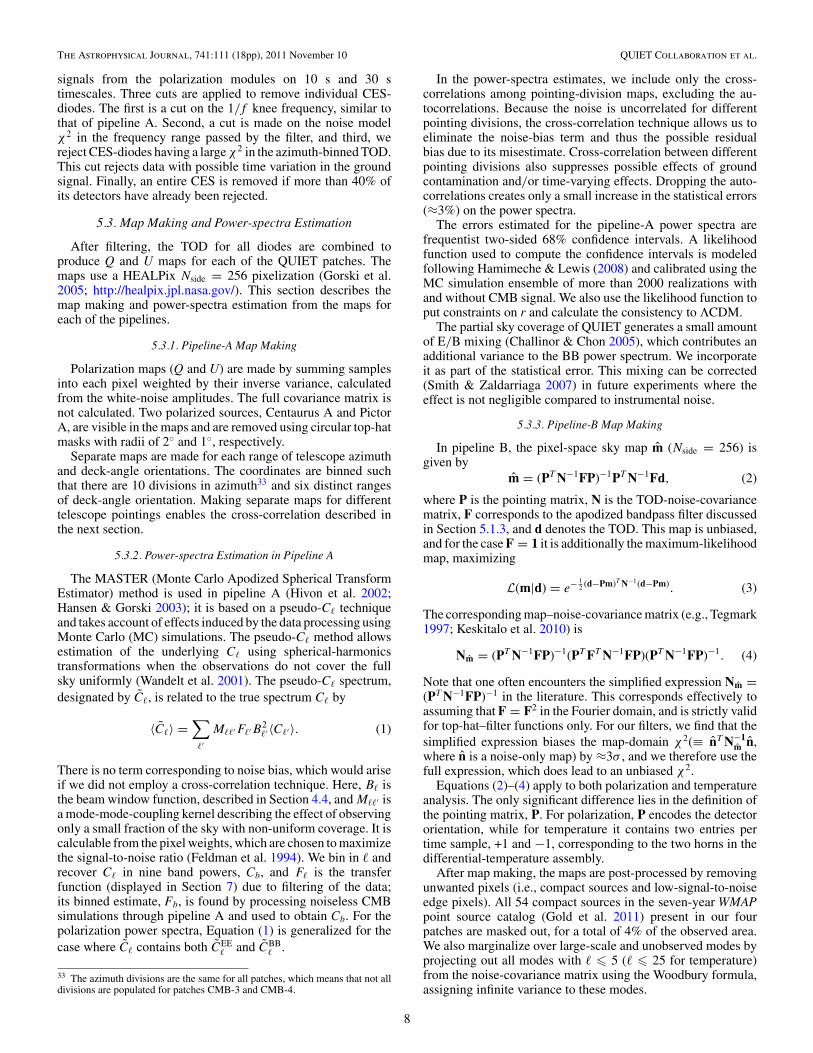
5.3. Map Making and Power-spectra Estimation
After filtering, the TOD for all diodes are combined toproduce Q and U maps for each of the QUIET patches. Themaps use a HEALPix Nside = 256 pixelization (Gorski et al.2005; http://healpix.jpl.nasa.gov/). This section describes themap making and power-spectra estimation from the maps foreach of the pipelines.
5.3.1. Pipeline-A Map Making
Polarization maps (Q and U) are made by summing samplesinto each pixel weighted by their inverse variance, calculatedfrom the white-noise amplitudes. The full covariance matrix isnot calculated. Two polarized sources, Centaurus A and PictorA, are visible in the maps and are removed using circular top-hatmasks with radii of 2◦ and 1◦, respectively.
Separate maps are made for each range of telescope azimuthand deck-angle orientations. The coordinates are binned suchthat there are 10 divisions in azimuth33 and six distinct rangesof deck-angle orientation. Making separate maps for differenttelescope pointings enables the cross-correlation described inthe next section.
5.3.2. Power-spectra Estimation in Pipeline A
The MASTER (Monte Carlo Apodized Spherical TransformEstimator) method is used in pipeline A (Hivon et al. 2002;Hansen & Gorski 2003); it is based on a pseudo-C! techniqueand takes account of effects induced by the data processing usingMonte Carlo (MC) simulations. The pseudo-C! method allowsestimation of the underlying C! using spherical-harmonicstransformations when the observations do not cover the fullsky uniformly (Wandelt et al. 2001). The pseudo-C! spectrum,designated by C!, is related to the true spectrum C! by
〈C!〉 =∑
!′
M!!′F!′B2!′ 〈C!′ 〉. (1)
There is no term corresponding to noise bias, which would ariseif we did not employ a cross-correlation technique. Here, B! isthe beam window function, described in Section 4.4, and M!!′ isa mode-mode-coupling kernel describing the effect of observingonly a small fraction of the sky with non-uniform coverage. It iscalculable from the pixel weights, which are chosen to maximizethe signal-to-noise ratio (Feldman et al. 1994). We bin in ! andrecover C! in nine band powers, Cb, and F! is the transferfunction (displayed in Section 7) due to filtering of the data;its binned estimate, Fb, is found by processing noiseless CMBsimulations through pipeline A and used to obtain Cb. For thepolarization power spectra, Equation (1) is generalized for thecase where C! contains both CEE
! and CBB! .
33 The azimuth divisions are the same for all patches, which means that not alldivisions are populated for patches CMB-3 and CMB-4.
In the power-spectra estimates, we include only the cross-correlations among pointing-division maps, excluding the au-tocorrelations. Because the noise is uncorrelated for differentpointing divisions, the cross-correlation technique allows us toeliminate the noise-bias term and thus the possible residualbias due to its misestimate. Cross-correlation between differentpointing divisions also suppresses possible effects of groundcontamination and/or time-varying effects. Dropping the auto-correlations creates only a small increase in the statistical errors(≈3%) on the power spectra.
The errors estimated for the pipeline-A power spectra arefrequentist two-sided 68% confidence intervals. A likelihoodfunction used to compute the confidence intervals is modeledfollowing Hamimeche & Lewis (2008) and calibrated using theMC simulation ensemble of more than 2000 realizations withand without CMB signal. We also use the likelihood function toput constraints on r and calculate the consistency to ΛCDM.
The partial sky coverage of QUIET generates a small amountof E/B mixing (Challinor & Chon 2005), which contributes anadditional variance to the BB power spectrum. We incorporateit as part of the statistical error. This mixing can be corrected(Smith & Zaldarriaga 2007) in future experiments where theeffect is not negligible compared to instrumental noise.
5.3.3. Pipeline-B Map Making
In pipeline B, the pixel-space sky map m (Nside = 256) isgiven by
m = (PT N−1FP)−1PT N−1Fd, (2)
where P is the pointing matrix, N is the TOD-noise-covariancematrix, F corresponds to the apodized bandpass filter discussedin Section 5.1.3, and d denotes the TOD. This map is unbiased,and for the case F = 1 it is additionally the maximum-likelihoodmap, maximizing
L(m|d) = e− 12 (d−Pm)T N−1(d−Pm). (3)
The corresponding map–noise-covariance matrix (e.g., Tegmark1997; Keskitalo et al. 2010) is
Nm = (PT N−1FP)−1(PT FT N−1FP)(PT N−1FP)−1. (4)
Note that one often encounters the simplified expression Nm =(PT N−1FP)−1 in the literature. This corresponds effectively toassuming that F = F2 in the Fourier domain, and is strictly validfor top-hat–filter functions only. For our filters, we find that thesimplified expression biases the map-domain χ2(≡ nT N−1
m n,where n is a noise-only map) by ≈3σ , and we therefore use thefull expression, which does lead to an unbiased χ2.
Equations (2)–(4) apply to both polarization and temperatureanalysis. The only significant difference lies in the definition ofthe pointing matrix, P. For polarization, P encodes the detectororientation, while for temperature it contains two entries pertime sample, +1 and −1, corresponding to the two horns in thedifferential-temperature assembly.
After map making, the maps are post-processed by removingunwanted pixels (i.e., compact sources and low-signal-to-noiseedge pixels). All 54 compact sources in the seven-year WMAPpoint source catalog (Gold et al. 2011) present in our fourpatches are masked out, for a total of 4% of the observed area.We also marginalize over large-scale and unobserved modes byprojecting out all modes with ! ! 5 (! ! 25 for temperature)from the noise-covariance matrix using the Woodbury formula,assigning infinite variance to these modes.
8
The Astrophysical Journal, 741:111 (18pp), 2011 November 10 QUIET Collaboration et al.
5.3.4. Power-spectra Estimation in Pipeline B
Given the unbiased map estimate, m, and its noise-covariancematrix, Nm, we estimate the binned CMB power spectra, Cb,using the Newton–Raphson optimization algorithm describedby Bond et al. (1998), generalized to include polarization. Inthis algorithm, one iterates toward the maximum-likelihoodspectra by means of a local quadratic approximation to the fulllikelihood. The iteration scheme in its simplest form is
δCb = 12
∑
b′
F−1bb′ Tr[(mmT − C)(C−1C,b′C−1)], (5)
where b denotes a multipole bin, C is the signal-plus-noisepixel-space covariance matrix, and C,b is the derivative of Cwith respect to Cb. The signal component of C is computedfrom the binned power spectra, Cb, and the noise component isbased on the noise model described in Section 5.1.2, includingdiode–diode correlations. Finally,
Fbb′ = 12
Tr(C−1C,bC−1C,b′ ) (6)
is the Fisher matrix. Additionally, we introduce a step lengthmultiplier, α, such that the actual step taken at iteration i isα δCb, where 0 < α ! 1 guarantees that C is positive definite.We adopt the diagonal elements of the Fisher matrix as theuncertainties on the band powers.
We start the Newton–Raphson search at C! = 0, and iterateuntil the change in the likelihood value is lower than 0.01 timesthe number of free parameters, corresponding roughly to a 0.01σuncertainty in the position of the multivariate peak. Typically,we find that 3–10 iterations are required for convergence.
Estimation of cosmological parameters, θ , is done by brute-force grid evaluation of the pixel-space likelihood,
L(θ ) ∝ −(1/2)dT C−1(θ )d√|C(θ )|
. (7)
Here, C(θ ) is the covariance matrix evaluated with a smoothspectrum, C!, parameterized by θ . In this paper, we onlyconsider one-dimensional likelihoods with a parameterizedspectrum of the form C! = a Cfid
! , a being a scale factor and Cfid!
a reference spectrum; the computational expense is thereforenot a limiting factor. Two different cases are considered, with abeing either the tensor-to-scalar ratio, r, or the amplitude of theEE spectrum, q, relative to the ΛCDM model.
5.4. Temperature Data Selection and Analysis
As described in Section 2, we dedicate one pair of modulesto differential-temperature measurements. While these modulesare useful for calibration purposes, when combined with ourpolarization data they also enable us to make self-containedmeasurements of the TE and TB power spectra.
For temperature, both pipelines adopt the pipeline-A data-selection criteria used for polarization analysis (see Section 5.2).The temperature-sensitive modules, however, are far moresusceptible to atmospheric contamination than the polarizationmodules. Thus, these cuts result in reduced efficiencies: 12.4%,6.9%, and 6.8% for patches CMB-1, CMB-2, and CMB-3,respectively.34 More tailoring of the cuts for these moduleswould improve efficiencies.
34 Patch CMB-4 is excluded due to low data-selection efficiency and a lack ofsufficient cross-linking.
In pipeline A, the analysis proceeds as described inSections 5.1.3, 5.3.1, and 5.3.2 except for two aspects. First,in the TOD processing a second-order polynomial is fit and re-moved from each telescope half-scan instead of a linear function.This suppresses the increased contamination from atmosphericfluctuations in the temperature data. Second, we employ an itera-tive map maker based on the algorithm described by Wright et al.(1996). Map making for differential receivers requires that eachpixel is measured at multiple array pointings or cross-linked. Inorder to improve cross-linking, we divide the temperature datainto only four maps by azimuth and deck angle, rather than the60 divisions used for polarization analysis. To calculate TE andTB power spectra, polarization maps are made for these fourdivisions, plus one additional map that contains all polarizationdata with pointings not represented in the temperature data.
For pipeline B, the algorithms for making temperature mapsand estimating power spectra are identical to the polarizationcase, as described in Sections 5.3.3 and 5.3.4.
6. ANALYSIS VALIDATION
The QUIET data analysis follows a policy of not looking atthe power spectra until the analysis is validated using a set ofpredefined tests for possible systematic effects.35 The validationtests consist of a suite of null tests, comparisons across multipleanalysis configurations, and consistency checks among powerspectra from different CMB patches. Data-selection criteria,filtering methods, and the division of data into maps for cross-correlation in pipeline A are all evaluated based on the testresults.
Details of tests found in this section describe pipeline A.While the pipeline-B analysis follows a similar program ofnull tests to verify the result, the increased computationalrequirements of the maximum-likelihood framework limit thenumber of tests that could be performed and require thosetests to be run using lower-resolution maps than for the non-null analysis. The bulk of this section treats validation ofthe polarization analysis; at the end, we briefly describe thetemperature analysis validation.
We conduct this validation in a blind-analysis framework toreduce experimenter bias, the influence of the experimenter’sknowledge of prior results and theoretical predictions on theresult (power spectra). Blind analysis, making the analysischoices without knowing the result, is a standard techniquefor minimizing this bias (Klein & Roodman 2005). In ourblind-analysis framework, we finalize all aspects of the dataanalysis including calibration, data selection, and evaluation ofthe systematic error. Only after the analysis is finalized and thefollowing validation tests pass do we examine the power spectra.
In a null test, the data are split into two subsets. Maps, m1and m2, are made from each subset. The power spectra ofthe difference map, mdiff ≡ (m1 − m2)/2, are analyzed forconsistency with the hypothesis of zero signal. The null suiteconsists of 42 tests,36 each targeting a possible source of signalcontamination or miscalibration. These are highly independenttests; the data divisions for different null tests are correlated atonly 8.8% on average. Nine tests divide the data by detectordiode based on susceptibility to instrumental effects, such asinstrumental polarization. Ten tests target effects that depend
35 Some systematic effects, such as a uniform responsivity-calibration error,cannot be detected by these techniques, and are addressed in Section 8.36 Only 41 null tests are performed for patch CMB-4; one test is droppedbecause there are no data in one of the subsets.
9

The Astrophysical Journal, 741:111 (18pp), 2011 November 10 QUIET Collaboration et al.
-10
0
10
20
30
40
0 100 200 300 400 500
C
(+1
)/2π
[ µK
2 ]
EEBB
-1
-0.5
0
0.5
0 100 200
Figure 6. EE and BB power spectra for the patch CMB-1 null test between Qand U detector diodes. The inset shows the low-! region in detail.
on the telescope pointing such as data taken at high or lowelevation. Five tests divide based on the proximity of the mainor sidelobe beams to known sources such as the Sun and Moon.Eight tests target residual contamination in the TOD usingstatistics mentioned in Section 5.2. Ten tests divide the databy environmental conditions such as ambient temperature orhumidity.
Each null test yields EE and BB power spectra in nine ! bins,calculated separately for each CMB patch. Figure 6 shows thepower spectra from one null test. Although the EB spectra arealso calculated for each null test, they are assigned lesser signif-icance since sources of spurious EB power will also result in thefailure of EE and BB null tests. Combining all EE and BB pointsfor all patches and null tests in the null suite yields a total of 3006null-spectrum points. For each power-spectrum bin b, we calcu-late the statistic χnull ≡ Cnull
b /σb, where Cnullb is the null power
and σb is the standard deviation of Cnullb in MC simulations. We
evaluate both χnull and its square; χnull is sensitive to system-atic biases in the null spectra while χ2
null is more responsive tooutliers. We run MC simulations of the full null suite to takeinto account the small correlation among the null tests and theslight non-Gaussianity of theχnull distribution. Non-Gaussianityis caused by the small number of modes at low !.
As we refine the data-selection criteria based on the resultsof the null suite, we use a second test to monitor changes inthe non-null power spectra. Using a blind-analysis framework,we compute the difference of the power spectra betweenany two iterations of the data selection without revealing thenon-null spectra. Furthermore, we randomize the sign of thedifference to hide the direction of the change; knowledge ofthe direction could allow experimenter bias (e.g., a preferencefor low BB power). Figure 7 shows the differences in thepower spectra between the final configuration and severalintermediate iterations of the data selection, starting with datasets that showed significant failures for the null-test suite.Statistically significant differences indicate a change in the levelof contamination in the selected data set. Our data-selectioncriteria are finalized when further iterations only result instatistically expected fluctuations. The sensitivity of this testis demonstrated by the fact that the expected fluctuations aremuch less than the statistical error of the final result.
Finally, the non-null power spectra are compared amongthe four CMB patches. A χ2 statistic is computed from thedeviation of each patch’s non-null power spectra from theweighted average over all patches. The total χ2 is comparedto MC simulations to compute probabilities to exceed (PTE).
-0.05
0
0.05
0.1
0.15
0.2
0.25
I II III IV V VI
∆C
(+1
)/2π
[µK
2 ]
Data Selection Iteration
ΛCDM EEEEBBEB
Figure 7. Power-spectra differences between the final data selection and sixof the 32 earlier data-selection iterations, ordered by date. The lowest-! bin ofpatch CMB-1 is shown. The error bars correspond to the expected fluctuationsdue to the differences in data selected, which are much smaller than the finalstatistical errors in this bin (≈0.10 µK2 for BB). Iterations that are closer to thefinal data selection have smaller errors. The expected EE power in this bin fromthe ΛCDM model is also shown for comparison.
10-5
10-4
10-3
10-2
10-1
100
-4 -3 -2 -1 0 1 2 3 4 5
Fra
ctio
nal C
ount
χnull
Pipeline A Pipeline B
0
0.02
0.04
0.06
0.08
0.1
0 0.1 0.2 0.3 0.4 0.5 0.6 0.7 0.8 0.9 1
Fra
ctio
nal C
ount
Probability To Exceed
Figure 8. Null-suite statistics. The upper panel shows a histogram of the χnullvalues for the pipeline-A null suite (circles), pipeline-B null suite (triangles),and the average of 1024 MC realizations of the pipeline-A null suite (grayhistogram). Both data and MC distributions show similar non-Gaussianity inthe χnull statistic. The shift in χnull seen for pipeline B, also seen in earlieriterations of pipeline A, is discussed in the text. The lower panel shows ahistogram of PTEs calculated from the χ2
null statistic (outliers from either sideof the upper distribution manifest as low PTEs).
When all aspects of the analysis are finalized, the last roundof null tests and CMB patch comparisons validates the non-null-power-spectra results. Figure 8 shows the distributions ofthe χnull statistic and of the PTEs corresponding to all χ2
nullvalues from the full null suite. In pipeline A, the distributionof χnull is consistent with the expectation from MC simulations.
10

The Astrophysical Journal, 741:111 (18pp), 2011 November 10 QUIET Collaboration et al.
Table 4Null-suite Probability to Exceed by Patch
Patch Pipeline A Pipeline B(%) (%)
CMB-1 44 7CMB-2 19 43CMB-3 16 23CMB-4 68 28
Note. PTEs calculated from the sums of the χ2null statistics, for EE and BB
spectra points, over the null tests for each patch.
The mean of the χnull distribution is 0.02±0.02; the mean of theMC-ensemble χnull distribution is also consistent with zero. Thedistribution of the χ2
null PTEs is uniform as expected. Table 4lists the PTEs for the sums of the χ2
null statistic over all bins ineach patch. Examinations of various subsets of the null suite,such as EE or BB only, do not reveal any anomalies. The EBnull spectra do not indicate any failure either. Patch comparisonPTEs are 0.16, 0.93, and 0.40 for EE, BB, and EB, respectively,demonstrating no statistically significant difference among thepatches.
A similar, but smaller, null suite is run by pipeline B.Specifically, 21 null tests are made at a HEALPix resolutionof Nside = 128. The results obtained in these calculations aresummarized in the bottom panel of Figure 8, and total PTEs foreach patch are listed in Table 4. As in pipeline A, no anomalousvalues are found.
Finally, we make a comment on the usefulness of the χnulldistribution (as opposed to the χ2
null distribution) for identifyingand quantifying potential contaminants. During the blind stageof the analysis, a positive bias in the χnull distribution of 0.21(0.19) was identified using pipeline A (B) (corresponding to21% (19%) of the statistical errors). The number from pipelineA was obtained when including autocorrelations in its power-spectra estimator. When excluding autocorrelations, and cross-correlating maps made from data divided by time (day by day),the bias decreased to 0.10. Further detailed studies lead to thedivision of data into maps based on the telescope pointing, asdescribed in Section 5.3; the result is an elimination of theobserved bias.
The maximum-likelihood technique employed by pipeline Bintrinsically uses autocorrelations, and a corresponding shift inthe χnull distribution is seen in Figure 8. However, as will beseen in Section 7, the power spectra from the two pipelines arein excellent agreement, thereby confirming that any systematicbias coming from including autocorrelations is well belowthe level of the statistical errors. We close this section bymentioning that we know of no other CMB experiment reportingan examination of the χnull distribution, which is sensitive toproblems not detected by examining the χ2
null distribution only.
6.1. Validation of the Temperature Analysis
A smaller number of null tests is used for the temperatureanalysis. Several are not applicable and others are discardeddue to lack of data with sufficient cross-linking. Even so, weare able to run suites of 29, 27, and 23 TT null tests on patchesCMB-1, CMB-2, and CMB-3, respectively. We calculate thesums of χ2
null statistics, yielding PTEs of 0.26 and 0.11 forpatches CMB-1 and CMB-2, respectively. No significant out-liers are found for these patches. However, a 5σ outlier in a
Table 5CMB-Spectra Band Powers from QUIET Q-band Data
! bin EE BB EB
25–75 0.33+0.16−0.11
a −0.01+0.06−0.04 0.00+0.07
−0.07
76–125 0.82+0.23−0.20 0.04+0.14
−0.12 −0.10+0.11−0.12
126–175 0.93+0.34−0.31 0.24+0.28
−0.25 0.71+0.22−0.20
176–225 1.11+0.58−0.52 0.64+0.53
−0.46 0.18+0.38−0.38
226–275 2.46+1.10−0.99 1.07+0.98
−0.86 −0.52+0.68−0.69
276–325 8.2+2.1−1.9 0.8+1.6
−1.4 0.9+1.3−1.3
326–375 11.5+3.6−3.3 −2.2+2.7
−2.4 0.0+2.0−2.0
376–425 15.0+6.2−5.8 −4.9+5.3
−4.9 3.2+3.9−3.9
426–475 21+13−11 2+11
−10 4.5+8.3−8.2
Notes. Units are thermodynamic temperatures, µK2, scaled as C!!(! + 1)/2π .a Patch CMB-1 has significant foreground contamination in the first EE bin.
single test37 is found in patch CMB-3, implying contamina-tion in its temperature map. CMB-3 is therefore excluded fromfurther analysis. We confirm consistency between the patchesCMB-1 and CMB-2 with a PTE of 0.26.
With no significant contamination in TT, EE, or BB spectra,one may be confident that the TE and TB spectra are similarlyclean. For confirmation, we calculate TE and TB null spectrafor the five null tests that are common to the temperature andpolarization analyses. These yield PTEs of 0.61 and 0.82 forTE, and 0.16 and 0.55 for TB, for patches CMB-1 and CMB-2,respectively, with no significant outliers. Patch consistencychecks give PTEs of 0.48 for TE and 0.26 for TB. Thus, theTE and TB power spectra, as well as the TT, pass all validationtests that are performed.
7. RESULTS
We report results from the first season of QUIET Q-band ob-servations: CMB power spectra, derived foreground estimates,and constraints on the tensor-to-scalar ratio, r.
7.1. Polarization Power Spectra
The CMB power spectra are reported in nine equally spacedbands with ∆! = 50, beginning at !min = 25. Given thepatch size, modes with ! < !min cannot be measured reliably.The correlation between neighboring bins is typically −0.1; itbecomes negligible for bins further apart.
The EE, BB, and EB polarization power spectra estimated byboth pipelines are shown in Figure 9. The agreement betweenthe results obtained by the two pipelines is excellent, andboth are consistent with the ΛCDM concordance cosmology.Our findings and conclusions are thus fully supported by bothpipelines. Only the statistical uncertainties are shown here; wetreat systematic errors in Section 8. Because the systematic erroranalysis was only done for pipeline A, we adopt its power-spectra results (tabulated in Table 5) as the official QUIETresults.
The bottom sub-panels in Figure 9 show the window andtransfer functions for each bin computed by pipeline A.Figure 10 shows the maps for patch CMB-1 computed bypipeline B, and Figure 11 shows the QUIET power spec-tra in comparison with the most relevant experiments in our
37 This null test divides the data based on array pointing.
11

The Astrophysical Journal, 741:111 (18pp), 2011 November 10 QUIET Collaboration et al.
0
10
20
30
40
50C
EE
(
+1)/
2 π [µ
K2 ]
ΛCDMPipeline APipeline B
0
1
2
0 100 200
0 100 200 300 400 5000
1
-5
0
5
10
15
20
CB
B
(+1
)/2π
[µK
2 ]
-0.5
0
0.5
1
0 100 200
0 100 200 300 400 5000
1
-5
0
5
10
15
20
CE
B
(+1
)/2π
[µK
2 ]
-0.5
0
0.5
1
0 100 200
0 100 200 300 400 5000
1
Figure 9. EE, BB, and EB power spectra from each QUIET pipeline, allfour patches combined. The insets show the low-! region in detail. Windowand transfer functions for each ! bin are shown below the correspondingpower spectra in black and gray, respectively. The window function combinesthe mode-mode-coupling kernel M!!′ with the beam (B!) and represents, incombination with the transfer function (F!), the response in each band tothe true C! spectrum. The EE point in the lowest-! bin includes foregroundcontamination from patch CMB-1. For this display, pipeline A shows frequentist68% confidence intervals while pipeline B uses the diagonal elements of theFisher matrix; the difference is most pronounced in the lowest-! bin where thelikelihood is the most non-Gaussian.
multipole range.38 Additional plots and data files are availableat the QUIET Web site at the University of Chicago.39
Fitting only a free amplitude, q, to the EE spectrum40 relativeto the seven-year best-fit WMAP ΛCDM spectrum (Larsonet al. 2011), we find q = 0.87 ± 0.10 for pipeline A and
38 Since Larson et al. (2011) do not provide an upper limit on the BB power,we use the diagonal elements of the Fisher matrix and show the points that are1.65 σ above their central values as 95% upper limits.39 http://quiet.uchicago.edu/results/index.html40 Only ! ! 76 are used in the EE fit and the χ2 calculation relative to ΛCDMbecause the first EE bin has a significant foreground contribution (seeSection 7.2).
Figure 10. Maps of patch CMB-1 in Galactic coordinates. The top row shows ourpolarization maps with compact sources masked (white disks). The bottom rowshows E and B modes decomposed using a generalized Wiener filter technique,implemented through Gibbs sampling where the signal term of the Wienerfilter is marginalized over the power spectra constrained by the data of thispatch themselves (Eriksen et al. 2004; Larson et al. 2007). The maps includeonly modes for ! ! 76 and smoothed to 1◦ FWHM; lower multipoles areremoved due to a significant foreground contribution. Note the clear differencein amplitude: the E modes show a high-signal-to-noise cosmological signalwhile the B modes are consistent with noise. Maps for the other patches areavailable online.
(A color, extended version of this figure is available in the online journal.)
q = 0.94 ± 0.09 for pipeline B. Taking into account the fullnon-Gaussian shapes of the likelihood functions, both resultscorrespond to more than a 10σ detection of EE power. Inparticular, in the region of the first peak, 76 ! ! ! 175,we detect EE polarization with more than 6σ significance,confirming the only other detection of this peak made by BICEPat higher frequencies. The χ2 relative to the ΛCDM model, withCEB! = CBB
! = 0, is 31.6 (24.3) with 24 degrees of freedom,corresponding to a PTE of 14% (45%) for pipeline A (B).
7.2. Foreground Analysis
In order to minimize possible foreground contamination,QUIET’s four CMB patches were chosen to be far from theGalactic plane and known Galactic synchrotron spurs. In theseregions, contributions from thermal dust emission are negligiblein Q band. Spinning dust is expected to be polarized at nomore than a few percent in Q band (Battistelli et al. 2006;Lopez-Caraballo et al. 2011), so we expect the contributionto polarized foreground emission in our patches to be small.We therefore consider only two dominant sources of possibleforeground contamination, namely, compact radio sources andGalactic diffuse synchrotron emission.
To limit the effect of compact radio sources, we apply acompact-source mask to our maps before computing the powerspectra, as described in Section 5. We also evaluate the CMBspectra both with and without the full WMAP temperaturecompact-source mask (Gold et al. 2011), and find no statisticallysignificant changes. The possible contribution from compactradio sources with fluxes below the WMAP detection level (1 Jy)is small: 0.003 µK2 at ! = 50 and 0.01 µK2 at ! = 100 (Battyeet al. 2011).41 We therefore conclude that our results are robust
41 The estimate is robust since 90% of the contribution comes from thehigh-flux population between 100 mJy and 1 Jy, where the distribution of thepopulation is well understood.
12

The Astrophysical Journal, 741:111 (18pp), 2011 November 10 QUIET Collaboration et al.
0
10
20
30
40
50
0 100 200 300 400 500
CE
E
(+1
)/2π
[µK
2 ]
ΛCDMQUIETBICEPQUaD
WMAP
0
1
2
0 100 200
10-3
10-2
10-1
100
101
102
50 500
CB
B
(+1
)/2π
[µK
2 ]
Primordial+LensingPrimordial (r = 0.2)
Gravitational Lensing
Figure 11. Top panel shows EE results with 68% C.L. error bars; the bottom panel shows BB 95% C.L. upper limits. For comparison, we also plot results fromprevious experiments (Brown et al. 2009; Chiang et al. 2010; Larson et al. 2011) and the ΛCDM model (the value r = 0.2 is currently the best 95% C.L. limit ontensor modes).(A color version of this figure is available in the online journal.)
with respect to contamination from compact radio sources andthat the dominant foreground contribution comes from diffusesynchrotron emission.
In Figure 12, we show the power spectra measured fromeach patch. The CMB-1 EE band power for the first bin is0.55 ± 0.14 µK2, a 3σ outlier relative to the expected ΛCDMband power of 0.13 µK2; while not significant enough to spoilthe overall agreement among the patches as shown in Section 6,this is a candidate for a bin with foreground contamination.
To estimate the Q-band polarized synchrotron contaminationin our CMB patches, we process the WMAP7 K-band (23 GHz)map through pipeline A and estimate its band power, CKK
b , aswell as the cross-spectra with the QUIET Q-band data, C
QKb .
These results are shown for the first bin (25 ! ! ! 75;b = 1) in Table 6, together with the corresponding QUIETband powers, C
QQb . Since foregrounds do not contribute to the
sample variance, the uncertainties for CKKb=1 and C
QKb=1 are given
by instrumental noise only, including contributions from bothWMAP and QUIET. For C
QQb=1, sample variance as predicted by
the ΛCDM model is also included.There is significant EE power in patch CMB-1 as mea-
sured by CKKb=1. We also find a correspondingly significant
Table 6Band and Cross Powers for ! = 25–75
Patch Spectrum CKKb=1 C
QKb=1 C
QQb=1
CMB-1 EE 17.4 ± 4.7 3.30 ± 0.55 0.55 ± 0.14BB 4.8 ± 4.5 0.40 ± 0.41 0.06 ± 0.08EB −6.2 ± 3.2 0.27 ± 0.38 0.10 ± 0.08
CMB-2 EE 5.5 ± 3.7 0.01 ± 0.56 0.23 ± 0.19BB 4.6 ± 3.4 0.18 ± 0.48 −0.11 ± 0.13EB −5.5 ± 2.8 −0.39 ± 0.41 −0.20 ± 0.12
CMB-3 EE 0.2 ± 1.9 0.64 ± 0.43 0.10 ± 0.18BB −0.3 ± 2.6 0.33 ± 0.35 0.01 ± 0.13EB 1.4 ± 1.7 −0.34 ± 0.30 −0.27 ± 0.11
CMB-4 EE −5.2 ± 5.1 0.7 ± 1.2 0.65 ± 0.58BB −2.6 ± 5.2 −0.1 ± 1.1 −0.37 ± 0.52EB −1.0 ± 3.9 0.0 ± 0.9 −0.15 ± 0.47
Notes. Power-spectra estimates for the first multipole bin for each patch,computed from the WMAP7 K-band data and the QUIET Q-band data. Theunits are !(!+ 1)C!/2π (µK2) in thermodynamic temperature. Uncertainties forCKK
b=1 and CQKb=1 include noise only. For C
QQb=1, they additionally include CMB
sample variance as predicted by ΛCDM. Values in bold are more than 2σ awayfrom zero.
13

The Astrophysical Journal, 741:111 (18pp), 2011 November 10 QUIET Collaboration et al.
-50
0
50
100
150
0 100 200 300 400 500
CE
E
(+1
)/2π
[µK
2 ]ΛCDMCMB-1CMB-2CMB-3CMB-4
Combined
0
1
2
0 100 200
-50
0
50
0 100 200 300 400 500
CB
B
(+1
)/2π
[µK
2 ]
-2
-1
0
1
0 100 200
Figure 12. CMB power spectra are shown for each patch individually. The topand bottom panels show the EE and BB spectra, respectively. The different errorbars for each patch mainly reflect the amounts of time each was observed.(A color version of this figure is available in the online journal.)
cross-correlation between the WMAP K band and the QUIET Qband, confirming that this excess power is not due to systematiceffects in either experiment and is very likely a foreground. Nosignificant power is found in any other case. The non-detectionof foreground power at ! > 75 is consistent with the expectedforeground dependence: ∝ !−2.5 (Carretti et al. 2010), and thelow power found in CKK
b=1.The excess power observed in the first EE bin of CMB-1 is
fully consistent with a typical synchrotron frequency spectrum.To see this, we extrapolate CKK
b=1 from K band to Q band,assuming a spectral index of β = −3.1 (Dunkley et al. 2009),and calculate the expected power in C
QKb=1 and C
QQb=1,
CQKb=1 = 1.05
1.01
(43.123
)β
CKKb=1 = 2.57 ± 0.69 µK2 , (8)
CQQb=1 =
[1.051.01
(43.123
)β]2
CKKb=1 = 0.38 ± 0.10 µK2 , (9)
where the prefactor accounts for the fact that β is defined inunits of antenna temperature, and the uncertainties are scaledfrom that of CKK
b=1. These predictions are fully consistent withthe observed values of C
QKb=1 and C
QQb=1, when combined with the
ΛCDM-expected power. We conclude that the excess power isindeed due to synchrotron emission.
7.3. Constraints on Primordial B Modes
We constrain the tensor-to-scalar ratio, r, using the QUIETmeasurement of the BB power spectrum at low multipoles
-2000
0
2000
4000
6000
CTT
(+1
)/2π
[µK
2 ]
ΛCDMPipeline APipeline B
-250
-150
-50
50
150
CTE
(+1
)/2π
[µK
2 ]
-60-40-20
0
0 100 200
-100
-50
0
50
100
150
0 100 200 300 400 500
CTB
(+1
)/2π
[µK
2 ]-20-10
0 10
0 100 200
Figure 13. Top row compares our temperature map to the WMAP seven-yearQ-band map (Jarosik et al. 2010) for patch CMB-1 in Galactic coordinates.Lower panels show the CMB temperature power spectra: TT, TE, and TB.(A color version of this figure is available in the online journal.)
(25 ! ! ! 175). Here, r is defined as the ratio of the primordial-gravitational-wave amplitude to the curvature-perturbation am-plitude at a scale k0 = 0.002 Mpc−1. We then fit our measure-ment to a BB-spectrum template computed from the ΛCDMconcordance parameters with r allowed to vary. For simplicity,we fix the tensor spectral index at nt = 0 in computing the tem-plate.42 This choice makes the BB-power-spectrum amplitudedirectly proportional to r.
For pipeline A, we find r = 0.35+1.06−0.87, corresponding to
r < 2.2 at 95% confidence. Pipeline B obtains r = 0.52+0.97−0.81.
The results are consistent; the lower panel of Figure 11 showsour limits on BB power in comparison with those from BICEP,QUaD, and WMAP. QUIET lies between BICEP and WMAPin significantly limiting r from measurements of CMB-B-modepower in our multipole range. Although we neither expectednor detected any BB foreground power, the detection of an EEforeground in patch CMB-1 suggests that BB foregrounds mightbe present at a smaller level. We emphasize that the upper limitwe report is therefore conservative.
7.4. Temperature Power Spectra
Figure 13 compares the QUIET and WMAP Q-band temper-ature maps and TT, TE, and TB power spectra. Agreement withthe ΛCDM model is good. This is a strong demonstration ofthe raw sensitivity of the QUIET detectors; the single QUIET
42 Our definition of r agrees with Chiang et al. (2010).
14

The Astrophysical Journal, 741:111 (18pp), 2011 November 10 QUIET Collaboration et al.
100 200 300 400
)2Kµ
EB
(
−510
−410
−310
−210
−110
1
10Statistical Error
EB
100 200 300 400
)2Kµ
BB
(
−510
−410
−310
−210
−110
1
10Statistical ErrorPrimodial (r=0.1)Lensing
BB
100 200 300 400
−510
−410
−310
−210
−110
1
10Statistical Error
CDMΛ
EE
PointingBeam Window FunctionPolarization AngleResponsivity ModelI to Q/U (monopole)I to Q/U (dipole, quadrupole)Sun Signal due to Far Sidelobes
C!
(+
1)/2
π[µ
K2]
Figure 14. Systematic uncertainty estimates for EE, BB, and EB power spectra. Estimates for a variety of effects (see the text) are shown for the three power spectra.In all cases, they are well below the statistical errors, which are also shown. In particular, the contaminations to the primordial-B-mode signal, at multipoles below100, are below the level of r = 0.1, even though we do not make a correction for the largest contaminant, the monopole leakage.(A color version of this figure is available in the online journal.)
differential-temperature assembly produces a high-signal-to-noise map using only 189 hr (after selection) of observations.The high sensitivity of these modules makes them very usefulfor calibration, pointing estimation, and consistency checks (seeSection 4).
8. SYSTEMATIC ERRORS
The passing of the null suite itself limits systematic uncer-tainty, but to get well below the statistical errors, dedicated stud-ies are needed. They are important for gaining confidence in theresult and also for evaluating the potential of the methods andtechniques we use for future efforts. We pay special attention toeffects that can generate false B-mode signals. Our methodol-ogy is to simulate and then propagate calibration uncertainties(see Section 4) and other systematic effects through the entirepipeline. The systematic errors in the power spectra are shownin Figure 14. The possible contaminations are well below thestatistical errors; in particular, the levels of spurious B modesare less than the signal of r = 0.1. This is the lowest level ofBB contamination yet reported by any CMB experiment. Thissection describes how each effect in Figure 14 is determined andconsiders three additional possible sources of contamination.
An uncertainty not shown in Figure 14 is that arising fromthe overall responsivity error estimate of 6% (12% in power-spectra units). After including the effect of possible time-dependent responsivity variations (4%, see below), the power-spectra uncertainty is 13%. It is multiplicative, affecting allpower-spectra results independent of multipole.
8.1. Beam Window Function and Pointing
The uncertainty in the beam window function is anothermultiplicative factor, one which increases with multipole. We
estimate this uncertainty using the difference of the beamwindow functions measured for the central module and themodules of the differential-temperature assembly, which are atthe edge of the array. The difference is statistically significant,coming from the different locations (with respect to the optics)in the focal plane; it is expected from the pre-season antennarange measurements.
Uncertainties in pointing lead to distortions in polarizationmaps. E power will be underestimated and spurious B power(if the distortions are nonlinear) generated (Hu et al. 2003).We quantify these effects by using the differences in pointingsolutions from two independent models: the fiducial model usedfor the analysis and an alternative model based on a differentset of calibrating observations. We also modeled and includedthe effects of the deck-angle-encoder shift which occurred for aportion of the season (Section 4.3).
8.2. Responsivity and Polarization Angle
Responsivity shifts, particularly within CESs, lead to distor-tions in the maps. Full-pipeline simulations quantify the shiftscaused by variations in the cryostat or electronics temperatures.Similarly shifts from using responsivities determined from theMoon data, Tau A data, or from the sparse wire grid, rather thanthose from the sky dips, are determined. We also incorporatethe uncertainty in the atmospheric-temperature model used inanalyzing the sky-dip data. The largest possible effects on thepower spectra are shown in Figure 14.
Uncertainties in the orientation of the polarization axes ofthe modules can lead to leakage between E and B modes. Toquantify this leakage, we use the differences in power spectrawhere these angles are determined from Moon data, Tau A data,and the sparse-wire-grid data. As expected, the largest effects
15

The Astrophysical Journal, 741:111 (18pp), 2011 November 10 QUIET Collaboration et al.
show up in EB power. We also estimate systematic error dueto possible fluctuation of the detector angles over the course ofthe season. The contribution is negligibly small compared tothe overall shift of the angles described above. Both effects areincluded in the “Polarization Angle” points in Figure 14.
8.3. Instrumental Polarization
As described in Section 4.5, the I to Q (U) leakage coefficientsfor the QUIET detector diodes are small: 1% (0.2%). Except inthe case of patch CMB-4, our scanning strategy significantlyreduces this effect with the combination of sky and deck-anglerotation.
We estimate spurious Q and U in the maps for each CES-diodeusing the WMAP temperature map and our known leakages.Shown in Figure 14 are the estimates of spurious EE, BB,and EB powers from full-pipeline simulations, where for eachrealization the spurious Q and U are added to the Q and U fromsimulated ΛCDM E modes. While this method has an advantageof being able to use the real (not simulated) temperature map,it does not incorporate TE correlation, which only affects thespurious EE power. As a complement, we repeat the study,but using simulated ΛCDM maps for both temperature andpolarization; this only changes the estimate of spurious EEpower by 30% at most. Because the spurious power is as smallas it is, we have treated it as a systematic rather than correctingfor it. Doing so would give us a further order of magnitudesuppression.
Differing beam ellipticities can also induce higher multipolepolarization signals. We measure these leakages from Tau A andJupiter observations and find that the higher-order multipolesare at most 0.1% of the main-beam peak amplitude. Thecorresponding effects on the power spectra, which are seen inFigure 14, are of little concern.
8.4. Far Sidelobes Seeing the Sun
While we make cuts to reduce the effects of far sidelobesseeing the Sun (Sections 2 and 5.1.3), small contaminationscould remain. We make full-season maps for each diode inSun-centered coordinates and then use these maps to addcontamination to full-pipeline CMB simulations. The excesspower found in the simulations is taken as the systematicuncertainty. We do not observe any signature from the Moon, nordo we cut on proximity to it. We estimate the related systematicerror and find that it is negligibly small compared to that assignedto the contamination from the Sun.
8.5. Other Possible Sources of Systematic Uncertainty
Here, we discuss a few additional potential sources ofsystematic uncertainty, which are found to be subdominant.
Ground-synchronous signals. QUIET’s far sidelobes do seethe ground for some diodes at particular elevations and deckangles. Ground pickup that is constant throughout a CES isremoved by our TOD filters; the net effect of this filtering in thefull-season maps is a correction of ≈1 µK.
The only concern is ground pickup that changes over theshort span of a single CES. We find little evidence for changeseven over the entire season, let alone over a single CES. Wetherefore conservatively place an upper limit on such changesusing the statistical errors on the ground-synchronous signal. Westart with the CES and module with the largest ground pickup.We then simulate one day’s worth of data, inserting a ground-synchronous signal that changes by its statistical error. Given the
distribution in the magnitude of the ground-synchronous signaland assuming that changes in this signal are proportional to thesize of the signal itself, by considering that the signals fromchanging pickup add incoherently into the maps made frommultiple CES-diodes at a variety of elevations and deck angles,we estimate an upper limit on residual B power from possiblechanging ground-pickup signals. The result is #10−4 µK2 atmultipoles below 100.
ADC nonlinearities. The possible residual after the correctionfor the nonlinearity in the ADC system results in effectssimilar to the I to Q (or U) leakage and the variation of theresponsivity during the CES. We estimate such effects basedon the uncertainty in the correction parameters, confirming thatthere is at most a 3% additional effect for the leakage bias, andthat the responsivity effect is also small, less than half of thesystematic error shown for the responsivity in Figure 14.
Data-selection biases. Cuts can cause biases if they are, forexample, too stringent. We expect none but to be sure we applyour selection criteria to 144 CMB + noise simulations. No biasis seen, and in particular we limit any possible spurious B modesfrom this source to #10−3 µK2 at multipoles below 100.
9. CONCLUSIONS
QUIET detects polarization in the EE power spectrum at43 GHz. We confirm with high significance the detection ofpolarization in the region of the first acoustic peak (Chiang et al.2010) in the multipole region ! = 76–175. We find no significantpower in either BB or EB between ! = 25 and ! = 475. Wemeasure the tensor-to-scalar ratio to be r = 0.35+1.06
−0.87.These results are supported by a very extensive suite of
null tests in which 42 divisions of data were used for eachof 33 different cut configurations. The selection criteria andsystematic errors were determined before the power spectrathemselves were examined. Biases were revealed during thisprocess, the last of which was a contamination present in thenull spectra at the level of about 20% of the statistical errors, buteliminated when cross-correlating maps with differing telescopepointings. The robustness of the final results is further supportedby having two pipelines with results in excellent agreement, eventhough one uses only cross-correlations while the other also usesautocorrelations.
Several possible systematic effects are studied with full end-to-end simulations. The possible contaminations in the B-modepower are thereby limited to a level smaller than for any otherpublished experiment: below the level of r = 0.1 for the pri-mordial B modes; simply correcting for the known level ofinstrumental polarization would reduce this to r < 0.03. Thisvery low level of systematic uncertainty comes from the com-bination of several important design features, including a newtime-stream “double-demodulation” technique, side-fed Drag-onian optics, natural sky rotation, and frequent deck rotation.
The correlation modules we use have a polarization sensitivity(Q and U combined) of 280 µK
√s, leading to an array sensitivity
of 69 µK√
s. Further, the 1/f noise observed in our detectorsis small: the median knee frequency is just 5.5 mHz. Oneimportant outcome of this work, then, is the demonstration thatour detectors, observing from a mid-latitude site, give excellentsensitivity and systematic immunity.
Because of our mid-latitude site, we are driven to collectdata in four separate patches. While we lose some sensitiv-ity (compared to going deeper on a single patch), there area few advantages that we have exploited. The patches arescanned differently, in terms of time of day and the degree of
16

The Astrophysical Journal, 741:111 (18pp), 2011 November 10 QUIET Collaboration et al.
cross-linking, and these differences allow some important sys-tematic checks. Another advantage concerns foregrounds.
Foreground contamination is expected to be one of the mainlimiting factors in the search for primordial B modes. Indeedwe report a 3σ detection of synchrotron emission in one ofour four CMB patches, originally chosen for their expected lowforeground levels. Our detection is only in EE; our BB 2σ limitpermits a BB signal about half as large. If we extrapolate thatvalue to the foreground minimum of about 94 GHz, we wouldhave synchrotron contamination at the level of r = 0.05 fromthis one patch. Neither WMAP nor Planck will have enoughsensitivity (Tauber et al. 2010) to sufficiently constrain thepolarized synchrotron amplitude at this level in any patch. Infact, our Q-band polarization maps are already as deep or deeperthan what Planck will achieve at the same frequency. Dedicatedlow-frequency observations are clearly needed to achieve suchconstraints. When foreground cleaning becomes important,consistency among separate patches will be an important handleon our understanding.
Further progress must be made through larger arrays andlonger integration times. In hand, we have data collected bythe 90 element W-band array with similar sensitivity to ourQ-band array and more than twice the number of observinghours. Results from the analysis of that data set will be reportedin future publications. A W-band receiver with the sensitivity toreach below the level of r = 0.01 is under development.
Support for the QUIET instrument and operation comesthrough the NSF cooperative agreement AST-0506648. Sup-port was also provided by NSF awards PHY-0355328,AST-0448909, AST-1010016, and PHY-0551142; KAKENHI20244041, 20740158, and 21111002; PRODEX C90284; aKIPAC Enterprise grant; and by the Strategic Alliance for theImplementation of New Technologies (SAINT).
Some work was performed on the Joint Fermilab-KICPSupercomputing Cluster, supported by grants from Fermilab, theKavli Institute for Cosmological Physics, and the University ofChicago. Some work was performed on the Titan Cluster, ownedand maintained by the University of Oslo and NOTUR (theNorwegian High Performance Computing Consortium), and onthe Central Computing System, owned and operated by theComputing Research Center at KEK. Portions of this work wereperformed at the Jet Propulsion Laboratory (JPL) and CaliforniaInstitute of Technology, operating under a contract with theNational Aeronautics and Space Administration. The Q-bandpolarimeter modules were developed using funding from theJPL R&TD program.
C.D. acknowledges an STFC Advanced Fellowship and anERC IRG grant under FP7. P.G.F. and J.A.Z. gratefully ac-knowledge the support of the Beecroft Institute of ParticleAstrophysics and Cosmology, the Oxford Martin School, andthe Science and Technology Facilities Council. L.B., R.B., andJ.M. acknowledge support from CONICYT project Basal PFB-06. R.B. acknowledges support from ALMA-Conicyt 31080022and 31070015. A.D.M. acknowledges a Sloan foundation fel-lowship.
PWV measurements were provided by the AtacamaPathfinder Experiment (APEX). We thank CONICYT for grant-ing permission to operate within the Chajnantor Scientific Pre-serve in Chile, and ALMA for providing site infrastructuresupport. Field operations were based at the Don Esteban fa-cility run by Astro-Norte. We are particularly indebted to theengineers and technician who maintained and operated the tele-
scope: Jose Cortes, Cristobal Jara, Freddy Munoz, and CarlosVerdugo.
In addition, we acknowledge the following people for theirassistance in the instrument design, construction, commission-ing, operation, and in data analysis: Augusto Gutierrez Aitken,Colin Baines, Phil Bannister, Hannah Barker, Matthew R.Becker, Alex Blein, Mircea Bogdan, April Campbell, AnushyaChandra, Sea Moon Cho, Emma Curry, Maire Daly, RichardDavis, Fritz Dejongh, Joy Didier, Greg Dooley, Hans Eide, WillGrainger, Jonathon Goh, Peter Hamlington, Takeo Higuchi, SethHillbrand, Christian Holler, Ben Hooberman, Kathryn D. Huff,William Imbriale, Koji Ishidoshiro, Eiichiro Komatsu, JosteinKristiansen, Richard Lai, Erik Leitch, Kelly Lepo, MarthaMalin, Mark McCulloch, Oliver Montes, David Moore, MakotoNagai, Ian O’Dwyer, Stephen Osborne, Stephen Padin, FelipePedreros, Ashley Perko, Alan Robinson, Jacklyn Sanders, DaleSanford, Mary Soria, Alex Sugarbaker, David Sutton, MatiasVidal, Liza Volkova, Edward Wollack, Stephanie Xenos, andMark Zaskowski.
REFERENCES
Battistelli, E. S., Rebolo, R., Rubino-Martın, J. A., et al. 2006, ApJ, 645,L141
Battye, R. A., Browne, I. W. A., Peel, M. W., Jackson, N. J., & Dickinson, C.2011, MNRAS, 413, 132
Bischoff, C., Hyatt, L., McMahon, J. J., et al. 2008, ApJ, 684, 771Bond, J. R., Jaffe, A. H., & Knox, L. 1998, Phys. Rev. D, 57, 2117Bornemann, J., & Labay, V. A. 1995, IEEE Trans. MTT, 43, 95Brown, M. L., Ade, P., Bock, J., et al. 2009, ApJ, 705, 978Buder, I. 2010, Proc. SPIE, 7741, 77411DCarretti, E., Haverkorn, M., McConnell, D., et al. 2010, MNRAS, 405,
1670Challinor, A., & Chon, G. 2005, MNRAS, 360, 509Chang, S., & Prata, A. 2004, IEEE Trans. Antennas Propag., 52, 12Chiang, H. C., Ade, P. A. R., Barkats, D., et al. 2010, ApJ, 711, 1123Dragone, C. 1978, Bell Syst. Tech. J., 57, 2663Dumoulin, R. N. 2010, Proc. SPIE, 7741, 77412NDunkley, J., Spergel, D. N., Komatsu, E., et al. 2009, ApJ, 701, 1804Eriksen, H. K., O’Dwyer, I. J., Jewell, J. B., et al. 2004, ApJS, 155, 227Feldman, H. A., Kaiser, N., & Peacock, J. A. 1994, ApJ, 426, 23Gold, B., Odegard, N., Weiland, J. L., et al. 2011, ApJS, 192, 15Gorski, K. M., Hivon, E., Banday, A. J., et al. 2005, ApJ, 622, 759Gundersen, J., & Wollack, E. 2009, J. Phys.: Conf. Ser., 155, 012005Gusten, R., Nyman, L. Å., Schilke, P., et al. 2006, A&A, 454, L13Hafez, Y., Davies, R. D., Davis, R. J., et al. 2008, MNRAS, 388, 1775Hamimeche, S., & Lewis, A. 2008, Phys. Rev. D, 77, 103013Hansen, F. K., & Gorski, K. M. 2003, MNRAS, 343, 559Hivon, E., Gorski, K. M., Netterfield, C. B., et al. 2002, ApJ, 567, 2Hu, W., Hedman, M., & Zaldarriaga, M. 2003, Phys. Rev. D, 67, 043004Imbriale, W. A., Gundersen, J., & Thompson, K. L. 2011, IEEE Trans. Antennas
Propag., 59, 1972Jarosik, N., Bennett, C. L., Dunkley, J., et al. 2011, ApJS, 192, 14Jarosik, N., Bennett, C. L., Halpern, M., et al. 2003, ApJS, 145, 413Kangaslahti, P., et al. 2006, in Microwave Symp., ed. J. Sowers & M. Thorburn
(Piscataway, NJ: IEEE), 89Keskitalo, R., Ashdown, M. A. J., Cabella, P., et al. 2010, A&A, 522, A94Klein, J. R., & Roodman, A. 2005, Ann. Rev. Nucl. Part. Sci., 55, 141Komatsu, E., Smith, K. M., Dunkley, J., et al. 2011, ApJS, 192, 18Kovac, J. M., Leitch, E. M., Pryke, C., et al. 2002, Nature, 420, 772Kusaka, A. 2010, in Proc. XLVth Recontres de Moriond, ed. E. Auge, J.
Dumarchez, & J. T. T. Van (Ha Noi: The Gio’i Publishers), 7Larson, D., Dunkley, J., Hinshaw, G., et al. 2011, ApJS, 192, 16Larson, D. L., Eriksen, H. K., Wandelt, B. D., et al. 2007, ApJ, 656, 653Leitch, E. M., Kovac, J. M., Halverson, N. W., et al. 2005, ApJ, 624, 10Liddle, A. R., & Lyth, D. H. 2000, Cosmological Inflation and Large-Scale
Structure (Cambridge: Cambridge Univ. Press)Lopez-Caraballo, C. H., Rubino-Martın, J. A., Rebolo, R., & Genova-Santos,
R. 2011, ApJ, 729, 25Lueker, M., Reichardt, C. L., Schaffer, K. K., et al. 2010, ApJ, 719, 1045Mauskopf, P. D., Ade, P. A. R., de Bernardis, P., et al. 2000, ApJ, 536,
L59
17
The Astrophysical Journal, 741:111 (18pp), 2011 November 10 QUIET Collaboration et al.
Mizugutch, Y., Akagawa, M., & Yokoi, H. 1976, in Antennas and PropagationSociety Int. Symp. (Piscataway, NJ: IEEE), 2
Monsalve, R. A. 2010, Proc. SPIE, 7741, 77412MMontroy, T. E., Ade, P. A. R., Bock, J. J., et al. 2006, ApJ, 647, 813Netterfield, C. B., Ade, P. A. R., Bock, J. J., et al. 2002, ApJ, 571, 604Newburgh, L. 2010, Proc. Twelfth Marcel Grossmann Meeting on General
Relativity, in pressPadin, S., Shepherd, M. C., Cartwright, J. K., et al. 2002, PASP, 114,
83Page, L., Hinshaw, G., Komatsu, E., et al. 2007, ApJS, 170, 335
Pardo, J., Cernicharo, J., & Serabyn, E. 2001, IEEE Trans. Antennas Propag.,49, 1683
Sievers, J. L., Achermann, C., Bond, J. R., et al. 2007, ApJ, 660, 976Smith, K. M., & Zaldarriaga, M. 2007, Phys. Rev. D, 76, 043001Tauber, J. A., Mandolesi, N., Puget, J.-L., et al. 2010, A&A, 520, A1Tegmark, M. 1997, ApJ, 480, L87Wandelt, B. D., Hivon, E., & Gorski, K. M. 2001, Phys. Rev. D, 64, 083003Weiland, J. L., Odegard, N., Hill, R. S., et al. 2011, ApJS, 192, 19Wright, E. L., Hinshaw, G., & Bennett, C. L. 1996, ApJ, 458, L53Wu, J. H. P., Zuntz, J., Abroe, M. E., et al. 2007, ApJ, 665, 55
18