first steps in the development of an architecture ... · first steps in the development of an...
TRANSCRIPT

Presentation No. 10771
First Steps in the Development of an Architecture Framework for a Product
Development ProcessPresenter: Jeffery L. Williams, PhD Candidate
Co-author: Jerrell T. Stracener, PhD
1

Presentation No. 10771
Research Foundation• This presentation is based on my PhD research to develop
a methodology an model to optimize the design of an organization (a complex system) for developing an Aerospace & Defense (A&D) system
• An organization is a function of the Product Development Processes and the goals & objectives of the end item system
• Therefore, the initial research is focused on the application of an Architecture Framework for a Product Development Process and its impact on the design of the organization
2

Presentation No. 10771
Where does the need for an Architecture Framework come from?
• Today’s A&D systems are becoming increasingly more complex• Today’s defense acquisition process is a complex phase-gated
process that forces A&D system developers to continually restructure its organizations in order to respond to changing demands
• Each A&D system developer needs to redefine itself at the start of each acquisition phase (and at key decision points within a phase) in order to accomplish the objectives of that phase in the most efficient manner possible
• In the Systems Engineering Journal, Vol. 12 No. 1 2009 p69-90, Tyson R. Browning identified Product Development Process (PDP) as a “kind of complex system” and he discussed the need for research regarding the application of Architecture Frameworks (AFs) to the development of PDPs.[1]
3

Presentation No. 10771
Response to the Need
• Melvin Conway stated in his paper, How Do Committees Invent?[2]
– Any organization that designs a system (defined more broadly here than just information systems) will inevitably produce a design whose structure is a copy of the organization’s communication structure.
• My research is focused on the design of organizations for the development of A&D systems. – These organizations are complex systems that are
continually adapting and modifying their needlines in order to operate efficiently
If an AF can be defined for an organization in the PDP, then it may be possible to determine a method to optimize the design of that organization.
Conway’s Law
4
Presentation No. 10771
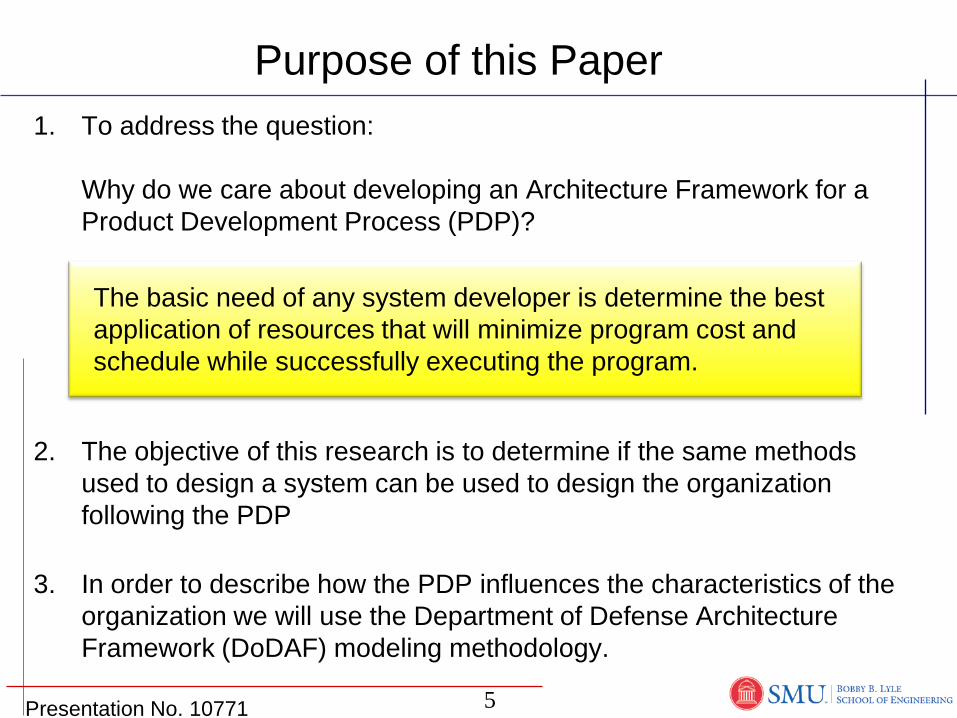
1. To address the question:
Why do we care about developing an Architecture Framework for a Product Development Process (PDP)?
2. The objective of this research is to determine if the same methods used to design a system can be used to design the organization following the PDP
3. In order to describe how the PDP influences the characteristics of the organization we will use the Department of Defense Architecture Framework (DoDAF) modeling methodology.
Purpose of this Paper
The basic need of any system developer is determine the best application of resources that will minimize program cost and schedule while successfully executing the program.
5

Presentation No. 10771
Why use DoDAF V2.0?1. DoDAF V2.0 is the “overarching, comprehensive framework and
conceptual model enabling the development of architectures to facilitate the ability of DoD managers at all levels make key decisions more effectively …”[3,pES-1]
2. The DoDAF is widely used by organizations developing system solutions for the DoD– Developers of A&D Systems are most likely to be the first to see
the need to optimize the design of the their organizations3. Version 2.0 added missing viewpoints necessary for modeling an
evolving organization– Capability Viewpoint– Data Information Viewpoint– Project Viewpoint
DoDAF V2.0 is a common methodology that architects already know!
6

Presentation No. 10771
How do we Tailor DoDAF V2.0?• The 6 steps used to tailor DoDAF V2.0 [3, p62]
1. Define Stakeholders2. Document the decisions made by the stakeholders3. Define information requirements for decisions4. Define DoDAF artifacts that support Stakeholder
decisions5. Align information requirements to the data sets for
decisions6. Develop architectural artifacts
7

Presentation No. 10771
Use of the Zachman Framework (ZF) [4]
• By mapping the stakeholders onto the ZF it helps us to:
– Understandeach stakeholder’sneeds
– Address thesix interrogatives
8

Presentation No. 10771
First Primary Stakeholders & Their Decisions1. Planner: Program Managers & Executive Leadership
– The Planner’s decisions are based on the scope of the effort and its impact on the enterprise
– Mapping of the Planner’s decision needs to the 6 interrogatives & DoDAF V2.0
Stakeholder What How Where When Who Why
Planner Business Entity
Business Function
Location Event (IMP)
The Org. Goals & Strategies
Planner DIV-1 OV-5a OV-2 CV-3PV-1
OV-4 AV-1CV-1OV-1
9

Presentation No. 10771
Second Primary Stakeholders & Their Decisions
2. Owner: Program Manager, Chief Engineer, Manufacturing & Logistics Leads– The Owner’s decisions are based on the definition of
the enterprise responsible for execution– Mapping of the Owner’s decision needs to the 6
interrogatives & DoDAF V2.0Stakeholder What How Where When Who Why
Owner Relationships of Business Entities
Process Models
Logistics of Execution
Master Schedule
Resource Groups
Business Plan or RFP
Owner DIV-2AV-2
OV-5bOV-6aOV-6b
OV-2 OV-6cCV-3CV-4CV-2PV-2
OV-3OV-4
AV-1CV-1PV-3
10

Presentation No. 10771
Third Primary Stakeholders & Their Decisions3. Designer: Chief Engineer, Manufacturing & Logistics
Leads– The Designer’s decisions based on defining the day-
to-day operations of the organization– Mapping of the Designer’s decision needs to the 6
interrogatives & DoDAF V2.0
Next Slide
11

Presentation No. 10771
Third Primary Stakeholders & Their DecisionsStakeholder What How Where When Who Why
Designer Data Products
Exchangeof DPs
Org Network
Sequence Org. ResourcesRq’d - Nos.
SOWs,CLINS, & Processes
Designer DIV-3SV-1SvcV-1SV-3SvcV-3aSvcV-3b
SV-4SvcV-4SV-5aSvcV-5aSV-5bSvcV-5bSV-6SvcV-6SV-7SvcV-7SV-10bSvcV-10bStdV-1
SV-2SvcV-2
SV-10cSvcV-10CCV-5
OV-2SV-6SvcV-6
StdV-2SV-10aSvcV-10ACV-6CV-7
Note 1: Select either a System or Service view of the organizationNote 2: SV-6 & SvcV-6 emphasis is on data & products flowing from/to org. needsNote 3: OV-2 definition is expanded at this level
12
Presentation No. 10771
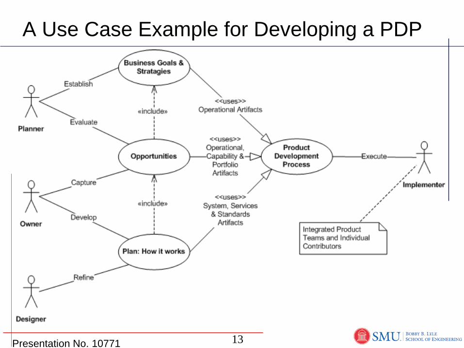
A Use Case Example for Developing a PDP
13

Presentation No. 10771
Definition of Scope of First Application• Analysis of Material Solution Analysis Phase to define
generic requirements for a SOW
14

Presentation No. 10771
Mapping of Requirements to AF ArtifactsRequirement OV-5a OV-5b SvcV-5 SV-5a SV-5b
DR.MSA.Cntrtr.001 ↑ ↑ ↑ ↑ ↑
DR.MSA.Cntrtr.002 ↑ ↑ ↑ ↑ ↑
DR.MSA.Cntrtr.003 ↑ ↑ ↑ ↑ ↑
DR.MSA.Cntrtr.004 ↑ ↑ ↑ ↑ ↑
DR.MSA.Cntrtr.005 ↑ ↑ ↑ ↑ ↑
DR.MSA.Cntrtr.006 ↑ ↑ ↑ ↑ ↑
DR.MSA.Cntrtr.007 ↑ ↑ ↑ ↑ ↑
The requirements derived from the description of the MSA phase in the Defense Acquisition Guidebook (DAG)[5] map to those artifacts associated with defining the activities to be performed.
15

Presentation No. 10771
Next Step• Develop example artifacts to guide an application of the
process– In work, initial artifacts are being created in the
modeling environment• Identification of program to support creation of an applied
architecture– Initial discussions with an Aerospace & Defense
developer were initiated on 8 Oct 2010• Development of the resultant network model to optimize
the program execution for the given constraints• Analysis of the optimized network model to determine
ideal organizational structure
16

Presentation No. 10771
Summary• An initial evaluation of the DoDAF 2.0 indicates that it has
sufficient breadth to support the development of a System Architecture of a Product Development Process
• The Viewpoints of the DoDAF 2.0 provide artifacts that address each of the decisions the primary stakeholders must address
• Final Observation – An extrapolation from Conway’s Law– If an AF is not used to produce a System Architecture
of an organization in the PDP, design flaws imposed on the organization will reflect the weaknesses of both the structure and process model of the enterprise.
17

Presentation No. 10771
References[1] The Many Views of a Process: Toward a Process
Architecture Framework for Product Development Processes, System Engineering Vol. 12, No. 1, 2009, p69-90.
[2] How Do Committees Invent?, Datamation, April 1968. Copy available at: http://www.melconway.com/Home/Committees_Paper.html
[3] DoD Achitecture Framework Version 2.0, Volume 1: Introduction, Overview, and Concepts, Manager’s Guide, 28 May 2009. The DoDAV C2 guides are available at: http://cio-nii.defense.gov/sites/dodaf20/index.html
[4] The Zachman Enterprise FrameworkTM . Available at: http://zachmaninternational.com/index.php and https://apps.adcom.uci.edu/EnterpriseArch/Zachman/
18
Presentation No. 10771
References[5] Defense Acquisition Guidebook. Available at:
https://dag.dau.mil/Pages/Default.aspx
19

Presentation No. 10771
Other papers of interest not referencesThe Use of Zachman Framework Primitives for Enterprise Modeling, Gundars Osvalds, Senior Principal Member of Technical Staff, Litton/TASC, 26 October 2000
A framework for information systems architecture, J.A. Zachman, IBM Systems Journal, Vol 26, No. 3, 1987.
20

Presentation No. 10771
Backup Slides
21

Presentation No. 10771
DoDAF 2.0 Definitions[3, p23-26]
Model DescriptionAV-1: Overview and Summary Information
Describes a Project's Visions, Goals, Objectives, Plans, Activities, Events, Conditions, Measures, Effects (Outcomes), and produced objects.
AV-2: Integrated Dictionary An architectural data repository with definitions of all terms used throughout the architectural data and presentations.
CV-1: Vision The overall vision for transformational endeavors, which provides a strategic context for the capabilities described and a high-level scope.
CV-2: Capability Taxonomy A hierarchy of capabilities which specifies all the capabilities that are referenced throughout one or more Architectural Descriptions.
CV-3: Capability Phasing The planned achievement of capability at different points in time or during specific periods of time. The CV-3 shows the capability phasing in terms of the activities, conditions, desired effects, rules complied with, resource consumption and production, and measures, without regard to the performer and location solutions.
CV-4: Capability Dependencies The dependencies between planned capabilities and the definition of logical groupings of capabilities.
22

Presentation No. 10771
DoDAF 2.0 Definitions[3, p23-26]
Model DescriptionCV-5: Capability to Organizational Development Mapping
The fulfillment of capability requirements shows the planned capability deployment and interconnection for a particular Capability Phase. The CV-5 shows the planned solution for the phase in terms of performers and locations and their associated concepts.
CV-6: Capability to Operational Activities Mapping
A mapping between the capabilities required and the operational activities that those capabilities support.
CV-7: Capability to Services Mapping
A mapping between the capabilities and the services that these capabilities enable.
DIV-1:Conceptual Data Model The required high-level data concepts and their relationships.
DIV-2: Logical Data Model The documentation of the data requirements and structural business process (activity) rules. In DoDAF V1.5, this was the OV-7.
DIV-3: Physical Data Model The physical implementation format of the Logical Data Model entities, e.g., message formats, file structures, physical schema. In DoDAF V1.5, this was the SV-11.
OV-1: High-Level Operational Concept Graphic
The high-level graphical/textual description of the operational concept.
OV-2: Operational Resource Flow Description
A description of the Resource Flows exchanged between operational activities.
23

Presentation No. 10771
DoDAF 2.0 Definitions[3, p23-26]
Model DescriptionOV-3: Operational Resource Flow Matrix
A description of the resources exchanged and the relevant attributes of the exchanges.
OV-4: Organizational Relationships Chart
The organizational context, role or other relationships among organizations.
OV-5a: Operational Activity Decomposition Tree
The capabilities and activities (operational activities) organized in a hierarchal structure.
OV-5b: Operational Activity Model The context of capabilities and activities (operational activities) and their relationships among activities, inputs, and outputs; Additional data can show cost, performers, or other pertinent information.
OV-6a: Operational Rules Model One of three models used to describe activity (operational activity). It identifies business rules that constrain operations.
OV-6b: State Transition Description One of three models used to describe operational activity (activity). It identifies business process (activity) responses to events (usually, very short activities).
OV-6c: Event-Trace Description One of three models used to describe activity (operational activity). It traces actions in a scenario or sequence of events.
24

Presentation No. 10771
DoDAF 2.0 Definitions[3, p23-26]
Model DescriptionPV-1: Project Portfolio Relationships It describes the dependency relationships between the
organizations and projects and the organizational structures needed to manage a portfolio of projects.
PV-2: Project Timelines A timeline perspective on programs or projects, with the key milestones and interdependencies.
PV-3: Project to Capability Mapping A mapping of programs and projects to capabilities to show how the specific projects and program elements help to achieve a capability.
SvcV-1 Services Context Description The identification of services, service items, and their interconnections.
SvcV-2 Services Resource Flow Description
A description of Resource Flows exchanged between services.
SvcV-3a Systems-Services Matrix The relationships among or between systems and services in a given Architectural Description.
SvcV-3b Services-Services Matrix The relationships among services in a given Architectural Description. It can be designed to show relationships of interest, (e.g., service-type interfaces, planned vs. existing interfaces).
SvcV-4 Services Functionality Description
The functions performed by services and the service data flows among service functions (activities).
25

Presentation No. 10771
DoDAF 2.0 Definitions[3, p23-26]
Model DescriptionSvcV-5 Operational Activity to Services Traceability Matrix
A mapping of services (activities) back to operational activities (activities).
SvcV-6 Services Resource Flow Matrix
It provides details of service Resource Flow elements being exchanged between services and the attributes of that exchange.
SvcV-7 Services Measures Matrix The measures (metrics) of Services Model elements for the appropriate time frame(s).
SvcV-8 Services Evolution Description
The planned incremental steps toward migrating a suite of services to a more efficient suite or toward evolving current services to a future implementation.
SvcV-9 Services Technology & Skills Forecast
The emerging technologies, software/hardware products, and skills that are expected to be available in a given set of time frames and that will affect future service development.
SvcV-10a Services Rules Model One of three models used to describe service functionality. It identifies constraints that are imposed on systems functionality due to some aspect of system design or implementation.
SvcV-10b Services State Transition Description
One of three models used to describe service functionality. It identifies responses of services to events.
26

Presentation No. 10771
DoDAF 2.0 Definitions[3, p23-26]
Model DescriptionSvcV-10c Services Event-Trace Description
One of three models used to describe service functionality. It identifies service-specific refinements of critical sequences of events described in the Operational Viewpoint.
StdV-1 Standards Profile The listing of standards that apply to solution elements.
StdV-2 Standards Forecast The description of emerging standards and potential impact on current solution elements, within a set of time frames.
SV-1 Systems Interface Description The identification of systems, system items, and their interconnections.
SV-2 Systems Resource Flow Description
A description of Resource Flows exchanged between systems.
SV-3 Systems-Systems Matrix The relationships among systems in a given Architectural Description. It can be designed to show relationships of interest, (e.g., system-type interfaces, planned vs. existing interfaces).
SV-4 Systems Functionality Description
The functions (activities) performed by systems and the system data flows among system functions (activities).
SV-5a Operational Activity to Systems Function Traceability Matrix
A mapping of system functions (activities) back to operational activities (activities).
27

Presentation No. 10771
DoDAF 2.0 Definitions[3, p23-26]
Model DescriptionSV-5b Operational Activity to Systems Traceability Matrix
A mapping of systems back to capabilities or operational activities (activities).
SV-6 Systems Resource Flow Matrix Provides details of system resource flow elements being exchanged between systems and the attributes of that exchange.
SV-7 Systems Measures Matrix The measures (metrics) of Systems Model elements for the appropriate timeframe(s).
SV-8 Systems Evolution Description The planned incremental steps toward migrating a suite of systems to a more efficient suite, or toward evolving a current system to a future implementation.
SV-9 Systems Technology & Skills Forecast
The emerging technologies, software/hardware products, and skills that are expected to be available in a given set of time frames and that will affect future system development.
SV-10a Systems Rules Model One of three models used to describe system functionality. It identifies constraints that are imposed on systems functionality due to some aspect of system design or implementation.
SV-10b Systems State Transition Description
One of three models used to describe system functionality. It identifies responses of systems to events.
28

Presentation No. 10771
DoDAF 2.0 Definitions[3, p23-26]
Model DescriptionSV-10c Systems Event-Trace Description
One of three models used to describe system functionality. It identifies system-specific refinements of critical sequences of events described in the Operational Viewpoint.
29