fisher gx 3 way control valve and actuator system - …€¦ · · 2018-03-27fisher™ gx 3-way...
TRANSCRIPT

www.Fisher.com
Fisher™ GX 3-Way Control Valve and Actuator SystemThe Fisher GX 3-Way is a compact, state-of-the-artcontrol valve and actuator system, designed toaccurately control water, oils, steam, and otherindustrial fluids. The robust GX 3-way valve package isperfectly suited to address the space limitations of theOEM industry.
The GX 3-Way is rugged, reliable, and easy to select.The internal valve trim is designed to ensure longservice life and avoiding unnecessary maintenance.The same construction may be used for bothconverging and diverging applications.
The GX 3-Way meets the requirements of both EN andASME standards. It is available with a completeaccessory package, including the FIELDVUE™ DVC2000and FIELDVUE DVC6200 integrated digital valvecontrollers.
The GX 3-Way trim characteristics are designed foraccurate temperature control in heat exchangerapplications.
� Side-Port Common (SPC)--The side flange is thecommon pipe connection for general converging(flow-mixing) and diverging (flow-splitting) service(see figure 4). Utilizes an unbalanced plug design.
� Bottom-Port Common (BPC)--A balanced designused for high pressure drop applications. Thebottom flange is the common pipe connection forboth converging and diverging service (see figures 8and 10).
� High-Temperature Side-Port Common (SPC)-- Theside flange is the common pipe connection forgeneral converging (flow-mixing) and diverging(flow-splitting) service (see figure 2). Utilizes anunbalanced plug design, a stem extension, a yokeextension, and includes ENVIRO-SEAL™ graphiteULF packing (figure 14) and a hard-faced seat ring.
Fisher GX 3-Way High-Temperature Control Valve andActuator
W9557
GE49204X0176
Fisher GX 3-Way Control Valve, Actuator, and FIELDVUEDVC2000 Digital Valve Controller
GX 3-Way Valve and ActuatorD103305X012
Product Bulletin51.1:GX 3-Way
August 2017

GX 3-Way Valve and ActuatorD103305X012
Product Bulletin51.1:GX 3-WayAugust 2017
2
Figure 1. Fisher GX 3-Way Control Valve Assembly with Port-Guided Contoured Plug (Side Port Common)
COMPACT FIELD-REVERSIBLEMULTI-SPRING ACTUATOR
INTEGRATED POSITIONERMOUNTING
NAMUR POSITIONERMOUNTING CAPABILITY
ONE-PIECE SCREWEDPACKING FOLLOWER
CLAMPED BONNET DESIGN
STANDARD ENVIRO-SEAL PACKING
W9578-1
Figure 2. Fisher GX 3-Way High-Temperature Control Valve Assembly with Port-Guided Contoured Plug (Side PortCommon)
COMPACT FIELD-REVERSIBLEMULTI-SPRING ACTUATOR
INTEGRATED POSITIONERMOUNTING
NAMUR POSITIONERMOUNTING CAPABILITY
ONE-PIECE SCREWEDPACKING FOLLOWER
CLAMPED BONNET DESIGN
STANDARD ENVIRO-SEAL GRAPHITE ULF PACKING
X0094-1
HARD-FACED SEAT AND GUIDESURFACES ON SEAT RING
STEM EXTENSION
YOKE EXTENSION
GRAPHITE SEAL RING

GX 3-Way Valve and ActuatorD103305X012
Product Bulletin51.1:GX 3-Way
August 2017
3
Features� Easy to size and select
� No actuator sizing required--selection is automatic
� Engineered for easy maintenance
� Maximum part commonality across sizes
� Replaceable trim
� Low lifetime costs
� Robust, low-profile design
� Available with integrated, easy-to-calibrate DVC2000 or DVC6200 digital valve controller
� Valve body sizes DN 25 to DN 100 (NPS 1 through 4)
� Pressure Classes PN 10-40, CL150 and 300
� High capacity design
� Valve body flow passage optimized for flow stability
� Shutoff capabilities: Class IV metal to metal
� ISO 5210 F7 mounting available for use with electric actuators
ContentsFeatures 3. . . . . . . . . . . . . . . . . . . . . . . . . . . . . . . . . . . . .Principle of Operation 10. . . . . . . . . . . . . . . . . . . . . . . .GX 3-Way Control Valve Specifications
and Materials of Construction 11. . . . . . . . . . . . . . .The GX 3-Way Diaphragm Actuator 14. . . . . . . . . . . . .
Valve-Actuator Dimensions and Weights 17. . . . . . . . .GX 3-Way Actuator Accessories 19. . . . . . . . . . . . . . . .The FIELDVUE DVC2000 Digital Valve Controller 19. .Optional Positioners and Instruments 20. . . . . . . . . . .

GX 3-Way Valve and ActuatorD103305X012
Product Bulletin51.1:GX 3-WayAugust 2017
4
Figure 3. Fisher GX 3-Way and FIELDVUE DVC2000 Digital Valve Controller
LINKAGE-LESS POSITIONFEEDBACK
PUSH-BUTTON INSTRUMENT SETUP
DVC2000COVER
INTEGRAL PNEUMATICPASSAGEWAYS
Optimized valve and actuator system. Productsimplicity and ease of selection form the foundation ofthe GX 3-Way. Mounted with a digital or analogpositioner, the GX 3-Way provides high performancecontrol across a wide range of process applications.
Compact actuator design. The multi-spring GX 3-Wayactuator is a compact robust design. The GX 3-Waydesign has been optimized to eliminate complicated3-way actuator sizing procedures - once the valve bodyand port size are selected, the actuator size is fixed.
Reliable Actuator Performance. Special actuatordiaphragm material helps reduce common problemssuch as air oxidation, thermal aging, low temperatureembrittlement, and loss of retention (see table 6). Thedouble-sided diaphragm within the actuator helpseliminate mechanical wear-induced failure.
Modular design. The design architecture has beenoptimized to maximize the use of common partsacross sizes. The actuator stem and stem connectorare used across all GX 3-Way sizes.
Low lifetime costs. Reduced product complexity, lowparts count, and part commonality all contribute toreduced inventory and maintenance costs.
Stable flow control. The flow cavity of the GX 3-Wayvalve body has been engineered to provide stable flowand reduce process variability. This linear stability forboth converging and diverging flow is perfectly suitedfor temperature and pH control applications.
Emission Requirements— ENVIRO-SEAL packingsystems provide an improved stem seal to helpprevent the loss of valuable or hazardous process fluid.The GX 3-Way comes standard with ENVIRO-SEAL PTFEpacking. ENVIRO-SEAL graphite ULF packing is alsoavailable for all sizes and is standard on hightemperature constructions.
Easy maintenance. The simple screwed seat-ring andone-piece plug and stem design provide easymaintenance. Design simplicity and partscommonality contribute to reduced spares inventory.The integrated DVC2000 and DVC6200 digital valvecontrollers allow easy instrument removal, without a

GX 3-Way Valve and ActuatorD103305X012
Product Bulletin51.1:GX 3-Way
August 2017
5
requirement for tubing disconnection or replacement(fail-down construction).
Digital valve controller. The GX 3-Way is available withthe DVC2000 digital valve controller. The DVC2000 iseasy to use, compact, and designed for easymounting. It converts a 4-20 mA input signal into apneumatic output signal, which feeds the control valveactuator. Instrument setup is performed with a pushbutton and LCD interface. This interface is protectedfrom the environment within a sealed enclosure. Theinterface supports multiple languages, includingGerman, French, Italian, Spanish, Chinese, Japanese,Portuguese, Russian, Polish, Czech, Arabic, andEnglish.
Intrinsic safety and non-incendive construction isavailable to CSA, FM, ATEX, and IEC standards. Anoptional module provides integrated limit switchesand a position transmitter.
Integrated mounting. The DVC2000 and DVC6200digital valve controllers integrally mount to the GX3-Way actuator, eliminating the need for mountingbrackets. The DVC2000 transmits a pneumatic signal
to the actuator casing via an air passage in the yokeleg, causing the valve to stroke (see figure 12). Thiseliminates the need for positioner-to-actuator tubingin the fail-down configuration.
The DVC2000 and DVC6200 mounting interfaces areidentical on both sides of the actuator yoke for valvebody sizes DN 25 through DN 100 (NPS 1 through 4).This symmetrical design allows the DVC2000 to beeasily moved from one side of the valve to the otherwithout the need to rotate the actuator.
Linkage-less feedback. The DVC2000 and DVC6200digital valve controllers offer as standard anon-contacting valve position feedback system. This isa true linkage-less design, which uses no levers and notouching parts between the valve stem and thepositioner.
Additional Accessory selection. The GX 3-Way isavailable with a variety of digital or analog positionersbesides the DVC2000 or DVC6200, as well as solenoidand limit switches. The actuator is also compatiblewith the IEC 60534-6-1 (NAMUR) positioner mountingstandard.

GX 3-Way Valve and ActuatorD103305X012
Product Bulletin51.1:GX 3-WayAugust 2017
6
Flow Directions -- Side Port Common ConstructionsFigure 4. Side Port Common Construction Details for Diverging Constructions
SEAT RING
VALVE PLUG
O-RING
BONNET
RIGHT PORT
BOTTOM PORT
DIVERGING
LEFT PORT(COMMON PORT)
W9580-1
Figure 5. Fisher GX 3-Way Flow Directions for Side Port Common Diverging Constructions
DIVERGINGPLUG DOWN (0% TRAVEL)
INLET
ALL FLOW PASSESTHROUGH FROM LEFT TO
RIGHT-HAND PORT
INLETINLET
DIVERGINGPLUG MID TRAVEL (50% TRAVEL)
DIVERGINGPLUG UP (100% TRAVEL)
FLOW IS DIVERTED EQUALLYBETWEEN BOTTOM AND
RIGHT-HAND PORT
ALL FLOW PASSESTHROUGH FROM LEFT TO
BOTTOM PORT

GX 3-Way Valve and ActuatorD103305X012
Product Bulletin51.1:GX 3-Way
August 2017
7
Figure 6. Side Port Common Construction Details for Converging Constructions
BOTTOM PORT
RIGHT PORTSEAT RING
LEFT PORT(COMMON PORT)
VALVE PLUG
O-RING
BONNET
CONVERGING
W9580-1
Figure 7. Fisher GX 3-Way Flow Directions for Side Port Common Converging Constructions
CONVERGINGPLUG DOWN (0% TRAVEL)
CONVERGINGPLUG MID TRAVEL (50% TRAVEL)
CONVERGINGPLUG UP (100% TRAVEL)
INLET INLET
INLET
BOTTOM PORT FLOW IS SHUTOFF. ALL RIGHT-HAND FLOW
EXITS LEFT-HAND PORT
FLOW IS MIXED EQUALLY FROMBOTTOM AND RIGHT-HAND
PORTS
RIGHT-HAND FLOW IS SHUTOFF.ALL BOTTOM PORT FLOW EXITS
THROUGH LEFT-HAND PORT
INLET

GX 3-Way Valve and ActuatorD103305X012
Product Bulletin51.1:GX 3-WayAugust 2017
8
Flow Directions -- Bottom Port Common ConstructionsFigure 8. Bottom Port Common Construction Details for Diverging Constructions
LOWER SEAT / CAGE
O-RING
BONNET
VALVE PLUG
SEAL RING
BACKUP RING
RIGHT PORT
BOTTOM PORT (COMMON PORT)
DIVERGING
LEFT PORT
W9579-1
Figure 9. Fisher GX 3-Way Flow Directions for Bottom Port Common Diverging Constructions
DIVERGINGPLUG DOWN (0% TRAVEL)
INLET
ALL FLOW EXITING RIGHT-HAND PORT
INLETINLET
DIVERGINGPLUG MID TRAVEL (50% TRAVEL)
DIVERGINGPLUG UP (100% TRAVEL)
FLOW IS DIVERTED EQUALLYBETWEEN BOTH SIDE PORTS
ALL FLOW IS EXITING THELEFT-HAND PORT

GX 3-Way Valve and ActuatorD103305X012
Product Bulletin51.1:GX 3-Way
August 2017
9
Figure 10. Bottom Port Common Construction Details for Converging Constructions
BOTTOM PORT (COMMON PORT)
RIGHT PORTLEFT PORT
CONVERGING
LOWER SEAT / CAGE
O-RING
BONNET
VALVE PLUG
SEAL RING
BACKUP RING
W9579-1
Figure 11. Fisher GX 3-Way Flow Directions for Bottom Port Common Converging Constructions
CONVERGINGPLUG DOWN (0% TRAVEL)
CONVERGINGPLUG MID TRAVEL (50% TRAVEL)
CONVERGINGPLUG UP (100% TRAVEL)
INLET INLET INLET
LEFT-HAND FLOW IS SHUTOFF. ALL RIGHT-HAND FLOW
EXITS THROUGH THE BOTTOM
FLOW IS MIXED EQUALLY FROMBOTH SIDE PORTS
RIGHT-HAND FLOW IS SHUTOFF.ALL LEFT-HAND FLOW EXITS
THROUGH THE BOTTOM PORT
INLET

GX 3-Way Valve and ActuatorD103305X012
Product Bulletin51.1:GX 3-WayAugust 2017
10
Principle of Operation - GX 3-Way ActuatorFigure 12. Fisher GX 3-Way Principle of Operation -- Actuator Fail Position
FAIL-DOWN (REVERSE-ACTING)(STANDARD CONFIGURATION)
FAIL-UP (DIRECT-ACTING)(OPTIONAL CONFIGURATION)
E0896-3
AIR SUPPLY
AIR SUPPLY
AIR VENT
AIR VENT
Integrated Air Supply. When mounted with theDVC2000 digital valve controller, the GX 3-Way usesan integrated actuator air supply system. In thefail-down configuration, air is supplied to the lower
actuator casing via a port on the actuator yoke face --no tubing is required. In the fail-up configuration, air issupplied to the upper casing via tubing.

GX 3-Way Valve and ActuatorD103305X012
Product Bulletin51.1:GX 3-Way
August 2017
11
GX 3-Way Control Valve Specifications and Materials ofConstructionTable 1. Fisher GX 3-Way Valve Specifications(1)
Specifications EN ASME
Valve Body Size DN 25, 40, 50, 80, 100 NPS 1, 1-1/2, 2, 3, 4
Pressure Rating PN 10 / 16 / 25 / 40 per EN 1092-1 CL150 / 300 per ASME B16.34
End Connections Flanged raised face per EN 1092-1Flanged raised face per ASME B16.5
Screwed (NPS 1, 1-1/2, and 2)
Valve Body Materials1.0619 steel ASME SA216 WCC steel
1.4409 stainless steel ASME SA351 CF3M stainless steel
Bonnet Materials 1.4409 stainless steel / CoCr-A SA351 CF3M SST / CoCr-A
Face-to-Face Dimensions See table 10
Shutoff per IEC 60534-4
and ANSI/FCI 70-2Metal seat - Class IV (standard)
SPC High Temperature construction: Metal seat - Class IV for bottom seat, Class II for upper seat
Flow Direction Converging and Diverging
Flow Coefficients See Fisher Catalog 12
Trim Style
Type Plug Sizes Description
Side Port Common All sizes Unbalanced Port-guided
Bottom Port Common All sizes Balanced Cage-guided
1. Stainless steel valve body is recommended for steam service when the high temperature construction is selected.
Table 2. Materials (Other Valve Components)Component Material
Packing Follower S21800 SST screwed follower
Body/Bonnet
Bolting and NutsSA193-B7 studs / SA194-2H nuts with NCF2 coating for carbon steel and stainless steel constructions
PackingENVIRO-SEAL Live-loaded PTFE V-ring (standard) with N07718 Belleville springs
ENVIRO-SEAL Live-loaded Graphite ULF (optional) with N07718 Belleville springs, (standard) on High Temperature construction.
Bonnet Gasket Graphite laminate
Bottom Port
Common Trim
(all sizes)
Carbon-Filled PTFE Seal Ring
Back-up Rings
NBR (Standard) -46 to 82�C (-50 to 180�F)
Ethylene Propylene [EPDM] (Optional): -46 to 232�C (-50 to 450�F) in steam and hot water;
-46 to 121�C (-50 to 250�F) in air (EPDM is not recommended for use in hydrocarbons)
FKM Fluorocarbon (Optional): -18 to 204�C (0 to 400�F) (Applicable in a wide variety of solvents, chemicals,
and hydrocarbons. Avoid use with steam, ammonia, or hot water over 82�C [180�F])
O-ring
(not used with
GX 3-Way High
Temperature)
NBR (Standard) -46 to 82�C (-50 to 180�F)
Ethylene Propylene [EPDM] (Optional): -46 to 232�C (-50 to 450�F) in steam and hot water;
-46 to 121�C (-50 to 250�F) in air (EPDM is not recommended for use in hydrocarbons)
FKM Fluorocarbon (Optional): -18 to 204�C (0 to 400�F) (Applicable in a wide variety of solvents, chemicals, and hydrocarbons.
Avoid use with steam, ammonia, or hot water over 82�C [180�F])
Seal Ring
(GX 3-Way High
Temperature)Graphite (FMS 17F27) -46 to 371�C (-50 to 700�F)
Stem Extension
(GX 3-Way High
Temperature)Stainless steel

GX 3-Way Valve and ActuatorD103305X012
Product Bulletin51.1:GX 3-WayAugust 2017
12
Table 3. Trim Materials (all sizes)Valve Body
ConstructionTrim Type Stem Plug Upper Seat Lower Seat/Cage(1)
Carbon steel (1.0619 /
WCC)
Bottom Port Common S31603 strain hardened CF3M Chrome-plated CF3M/CoCr-A CF3M
Side Port Common S31603 strain hardened CF3M CF3M/CoCr-A CF3M
Stainless steel
(1.4409 / CF3M)
Bottom Port Common S31603 strain hardened CF3M Chrome-plated CF3M/CoCr-A CF3M
Side Port Common S31603 strain hardened CF3M CF3M/CoCr-A CF3M
1. HT construction includes CF3M/CoCr-A lower seating. Seat and guide surfaces are hard-faced.
Table 4. Allowable Temperature Ranges for Valve Body, Bonnet and Trim(1)
VALVE BODY / BONNETMATERIAL
BONNET STYLEENVIRO-SEAL
PACKINGGASKET TRIM STYLE
TEMPERATURE
�C �F
Min Max Min Max
1.0619/SA216 WCC
SteelStandard
PTFE or
Graphite ULFGraphite laminate
Bottom Port Common,
Side Port Common-29 232 -20 450
1.4409/SA351 CF3M SST StandardPTFE or
Graphite ULFGraphite laminate
Bottom Port Common,
Side Port Common-46 232 -50 450
1.0619/SA216 WCC
SteelHT Construction Graphite ULF Graphite laminate Side Port Common -29 371 -20 700
1.4409/SA351 CF3M SST HT Construction Graphite ULF Graphite laminate Side Port Common -46 371 -50 700
1. Bonnet O-ring and back-up ring materials used on BPC trim may be limited by temperature and application.
Figure 13. Material Pressure/Temperature Curves

GX 3-Way Valve and ActuatorD103305X012
Product Bulletin51.1:GX 3-Way
August 2017
13
Figure 14. Fisher GX 3-Way Packing
STANDARD BONNET WITH ENVIRO-SEAL LIVE-LOADED PTFE PACKING SETDN 25 through DN 100 (NPS 1 through 4)
STANDARD BONNET WITH OPTIONAL ENVIRO-SEAL LIVE-LOADED GRAPHITE ULFPACKING SET (STANDARD ON HIGH TEMPERATURE CONSTRUCTION)
DN 25 through DN 100 (NPS 1 through 4)
BELLEVILLESPRING PACK
PACKING SPACER
PACKINGRINGS
PACKINGBOX RING
GE38594_ULF
BELLEVILLESPRING PACK
PACKING SPACER
PACKING SETANTI-EXTRUSIONWASHER
PACKINGBOX RING
ANTI-EXTRUSIONWASHER
E0897

GX 3-Way Valve and ActuatorD103305X012
Product Bulletin51.1:GX 3-WayAugust 2017
14
The GX 3-Way DiaphragmActuator
Figure 15. Fisher GX 3-Way Actuator
W8487-3
The GX 3-Way uses a multi-spring, pneumaticdiaphragm actuator (see figure 15). It is capable of airsupply pressures up to 5.0 barg (72 psig), allowingvalve shutoff at high pressure drops (see table 8).
The GX 3-Way product selection system automaticallymatches the actuator to the valve, eliminating theneed for complex actuator sizing procedures.
The multiple spring design provides the preload,eliminating the need for bench set adjustment. Theactuator is available in fail-down and fail-upconfigurations.
The GX 3-Way actuator can be used for throttling oron-off service.
The GX 3-Way is available with the integratedDVC2000 digital valve controller. Other digital andanalog positioners are available, as well as optionalsolenoids and limit switches.
Table 5. Actuator SpecificationsDescription Pneumatic spring-return diaphragm actuator
Operating PrincipleFail-down (standard configuration)
Fail-up (optional configuration)
Operating Pressure Ranges See tables 8 and 9
Ambient Temperature -46 to 82�C (-50 to 180�F)
Pressure Connection (Fail-Up Construction) G 1/4 internal casing connection
Finish Powder coat polyester
Table 6. Materials of ConstructionPart Material
Upper and Lower Casings AISI 1010 stamped carbon steel
Springs Steel
Diaphragm NBR and nylon
Diaphragm Plate AISI 1010 stamped carbon steel
Yoke and Yoke Extension on High Temperature Construction Carbon steel
Casing Fasteners A2-70 stainless steel bolts and nuts
Actuator Rod Stainless steel
Stem Connector CF3M
Stem Connector Fasteners SA193-B7 bolts with NCF2 coating
Stem Bushing High-density polyethylene (HDPE)
Stem Seal NBR

GX 3-Way Valve and ActuatorD103305X012
Product Bulletin51.1:GX 3-Way
August 2017
15
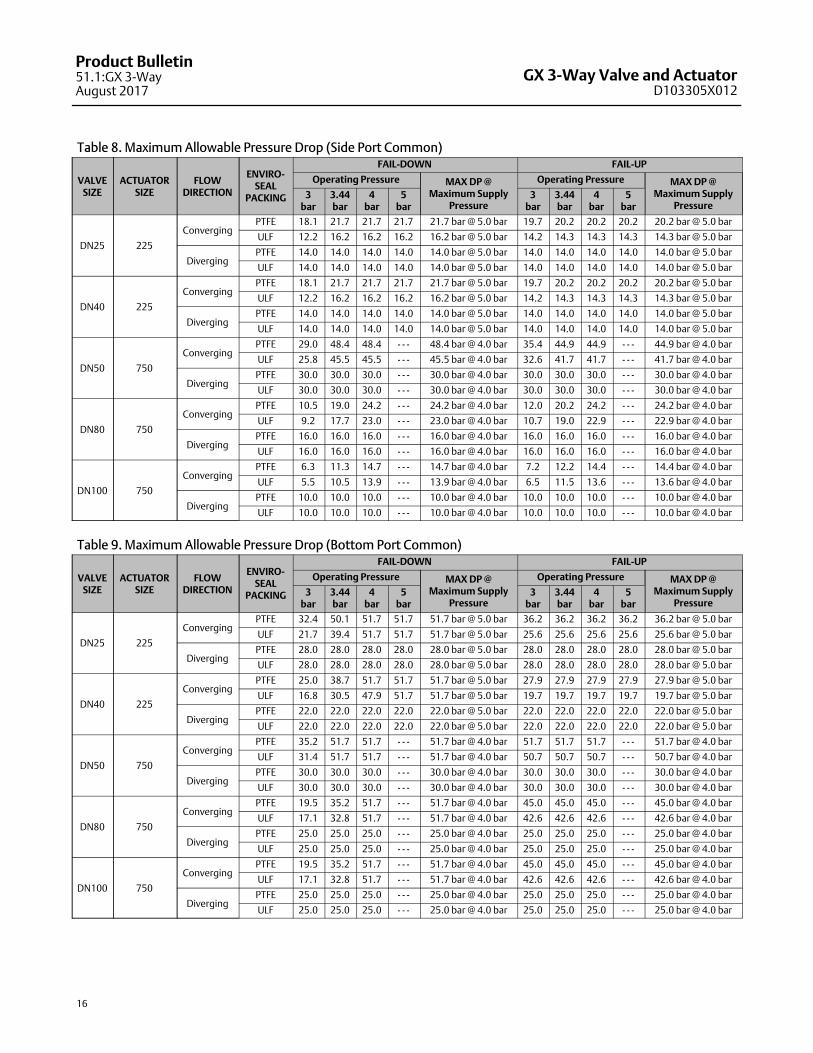
Actuator Selection
With the GX 3-Way, actuator selection has never beeneasier. Once the valve size has been determined, theactuator is automatically selected.
The following tables provide the maximum allowablepressure drops for the GX 3-Way. See table 8 for SidePort Common construction and table 9 for BottomPort Common construction. For optimal performance,the GX 3-Way should be operated with a FIELDVUEdigital valve controller.
GX ISO 5210 ElectricActuator MountingElectric actuator mounting is available for anymanufacturing models that comply with ISO 5210,Flange type F7. The mounting offering includes a GXyoke, actuator rod adaptor, spacer, and bolting.
Thrust limitations apply when sizing electric actuators(see table 7).
Mounting offering can be engineered if not alreadyavailable for a selected actuator. For additionalinformation, contact your Emerson sales office or LocalBusiness Partner.
Table 7. Fisher GX 3-Way Maximum Allowable Thrust for use with ISO 5210 Electric Actuators (THRUST LIMITATIONS APPLY IN BOTH TRAVEL DIRECTIONS)
VALVE SIZESTEM DIAMETER TRAVEL
STEM MATERIALMAXIMUM THRUST
mm mm N lbf
DN25-DN40
(NPS 1 to 1-1/2)10 19 S31603 6900 1550
DN50 (NPS 2) 14 19 S31603 14000 3150
DN80-DN100
(NPS 3 to 4)14 38 S31603 14000 3150
GX 3-Way Valve and ActuatorD103305X012
Product Bulletin51.1:GX 3-WayAugust 2017
16
Table 8. Maximum Allowable Pressure Drop (Side Port Common)
VALVESIZE
ACTUATORSIZE
FLOWDIRECTION
ENVIRO-SEAL
PACKING
FAIL-DOWN FAIL-UP
Operating Pressure MAX DP @Maximum Supply
Pressure
Operating Pressure MAX DP @Maximum Supply
Pressure3
bar3.44bar
4bar
5bar
3bar
3.44bar
4bar
5bar
DN25 225
ConvergingPTFE 18.1 21.7 21.7 21.7 21.7 bar @ 5.0 bar 19.7 20.2 20.2 20.2 20.2 bar @ 5.0 bar
ULF 12.2 16.2 16.2 16.2 16.2 bar @ 5.0 bar 14.2 14.3 14.3 14.3 14.3 bar @ 5.0 bar
DivergingPTFE 14.0 14.0 14.0 14.0 14.0 bar @ 5.0 bar 14.0 14.0 14.0 14.0 14.0 bar @ 5.0 bar
ULF 14.0 14.0 14.0 14.0 14.0 bar @ 5.0 bar 14.0 14.0 14.0 14.0 14.0 bar @ 5.0 bar
DN40 225
ConvergingPTFE 18.1 21.7 21.7 21.7 21.7 bar @ 5.0 bar 19.7 20.2 20.2 20.2 20.2 bar @ 5.0 bar
ULF 12.2 16.2 16.2 16.2 16.2 bar @ 5.0 bar 14.2 14.3 14.3 14.3 14.3 bar @ 5.0 bar
DivergingPTFE 14.0 14.0 14.0 14.0 14.0 bar @ 5.0 bar 14.0 14.0 14.0 14.0 14.0 bar @ 5.0 bar
ULF 14.0 14.0 14.0 14.0 14.0 bar @ 5.0 bar 14.0 14.0 14.0 14.0 14.0 bar @ 5.0 bar
DN50 750
ConvergingPTFE 29.0 48.4 48.4 - - - 48.4 bar @ 4.0 bar 35.4 44.9 44.9 - - - 44.9 bar @ 4.0 bar
ULF 25.8 45.5 45.5 - - - 45.5 bar @ 4.0 bar 32.6 41.7 41.7 - - - 41.7 bar @ 4.0 bar
DivergingPTFE 30.0 30.0 30.0 - - - 30.0 bar @ 4.0 bar 30.0 30.0 30.0 - - - 30.0 bar @ 4.0 bar
ULF 30.0 30.0 30.0 - - - 30.0 bar @ 4.0 bar 30.0 30.0 30.0 - - - 30.0 bar @ 4.0 bar
DN80 750
ConvergingPTFE 10.5 19.0 24.2 - - - 24.2 bar @ 4.0 bar 12.0 20.2 24.2 - - - 24.2 bar @ 4.0 bar
ULF 9.2 17.7 23.0 - - - 23.0 bar @ 4.0 bar 10.7 19.0 22.9 - - - 22.9 bar @ 4.0 bar
DivergingPTFE 16.0 16.0 16.0 - - - 16.0 bar @ 4.0 bar 16.0 16.0 16.0 - - - 16.0 bar @ 4.0 bar
ULF 16.0 16.0 16.0 - - - 16.0 bar @ 4.0 bar 16.0 16.0 16.0 - - - 16.0 bar @ 4.0 bar
DN100 750
ConvergingPTFE 6.3 11.3 14.7 - - - 14.7 bar @ 4.0 bar 7.2 12.2 14.4 - - - 14.4 bar @ 4.0 bar
ULF 5.5 10.5 13.9 - - - 13.9 bar @ 4.0 bar 6.5 11.5 13.6 - - - 13.6 bar @ 4.0 bar
DivergingPTFE 10.0 10.0 10.0 - - - 10.0 bar @ 4.0 bar 10.0 10.0 10.0 - - - 10.0 bar @ 4.0 bar
ULF 10.0 10.0 10.0 - - - 10.0 bar @ 4.0 bar 10.0 10.0 10.0 - - - 10.0 bar @ 4.0 bar
Table 9. Maximum Allowable Pressure Drop (Bottom Port Common)
VALVESIZE
ACTUATORSIZE
FLOWDIRECTION
ENVIRO-SEAL
PACKING
FAIL-DOWN FAIL-UP
Operating Pressure MAX DP @Maximum Supply
Pressure
Operating Pressure MAX DP @Maximum Supply
Pressure3
bar3.44bar
4bar
5bar
3bar
3.44bar
4bar
5bar
DN25 225
ConvergingPTFE 32.4 50.1 51.7 51.7 51.7 bar @ 5.0 bar 36.2 36.2 36.2 36.2 36.2 bar @ 5.0 bar
ULF 21.7 39.4 51.7 51.7 51.7 bar @ 5.0 bar 25.6 25.6 25.6 25.6 25.6 bar @ 5.0 bar
DivergingPTFE 28.0 28.0 28.0 28.0 28.0 bar @ 5.0 bar 28.0 28.0 28.0 28.0 28.0 bar @ 5.0 bar
ULF 28.0 28.0 28.0 28.0 28.0 bar @ 5.0 bar 28.0 28.0 28.0 28.0 28.0 bar @ 5.0 bar
DN40 225
ConvergingPTFE 25.0 38.7 51.7 51.7 51.7 bar @ 5.0 bar 27.9 27.9 27.9 27.9 27.9 bar @ 5.0 bar
ULF 16.8 30.5 47.9 51.7 51.7 bar @ 5.0 bar 19.7 19.7 19.7 19.7 19.7 bar @ 5.0 bar
DivergingPTFE 22.0 22.0 22.0 22.0 22.0 bar @ 5.0 bar 22.0 22.0 22.0 22.0 22.0 bar @ 5.0 bar
ULF 22.0 22.0 22.0 22.0 22.0 bar @ 5.0 bar 22.0 22.0 22.0 22.0 22.0 bar @ 5.0 bar
DN50 750
ConvergingPTFE 35.2 51.7 51.7 - - - 51.7 bar @ 4.0 bar 51.7 51.7 51.7 - - - 51.7 bar @ 4.0 bar
ULF 31.4 51.7 51.7 - - - 51.7 bar @ 4.0 bar 50.7 50.7 50.7 - - - 50.7 bar @ 4.0 bar
DivergingPTFE 30.0 30.0 30.0 - - - 30.0 bar @ 4.0 bar 30.0 30.0 30.0 - - - 30.0 bar @ 4.0 bar
ULF 30.0 30.0 30.0 - - - 30.0 bar @ 4.0 bar 30.0 30.0 30.0 - - - 30.0 bar @ 4.0 bar
DN80 750
ConvergingPTFE 19.5 35.2 51.7 - - - 51.7 bar @ 4.0 bar 45.0 45.0 45.0 - - - 45.0 bar @ 4.0 bar
ULF 17.1 32.8 51.7 - - - 51.7 bar @ 4.0 bar 42.6 42.6 42.6 - - - 42.6 bar @ 4.0 bar
DivergingPTFE 25.0 25.0 25.0 - - - 25.0 bar @ 4.0 bar 25.0 25.0 25.0 - - - 25.0 bar @ 4.0 bar
ULF 25.0 25.0 25.0 - - - 25.0 bar @ 4.0 bar 25.0 25.0 25.0 - - - 25.0 bar @ 4.0 bar
DN100 750
ConvergingPTFE 19.5 35.2 51.7 - - - 51.7 bar @ 4.0 bar 45.0 45.0 45.0 - - - 45.0 bar @ 4.0 bar
ULF 17.1 32.8 51.7 - - - 51.7 bar @ 4.0 bar 42.6 42.6 42.6 - - - 42.6 bar @ 4.0 bar
DivergingPTFE 25.0 25.0 25.0 - - - 25.0 bar @ 4.0 bar 25.0 25.0 25.0 - - - 25.0 bar @ 4.0 bar
ULF 25.0 25.0 25.0 - - - 25.0 bar @ 4.0 bar 25.0 25.0 25.0 - - - 25.0 bar @ 4.0 bar

GX 3-Way Valve and ActuatorD103305X012
Product Bulletin51.1:GX 3-Way
August 2017
17
Valve-Actuator Dimensions and WeightsTable 10. Fisher GX 3-Way Dimensions and Weights (Standard and High Temperature Constructions)
VALVESIZE
TYPE
PORT DIA
ACTUATORSIZE
TRAVEL
A B C
Upper LowerPN10 -PN40
CL150 CL300PN10 -PN40
CL150 CL300 Bonnet
mm mm mm mm mm mm mm mm mm mm
DN 25/
NPS 1
BPC 29 36225 19 197 184 197 98.5 92 98.5 73
SPC 36 36
DN 40/
NPS
1-1/2
BPC 39 46225 19 235 222 235 117.5 111 117.5 76
SPC 36 36
DN 50/
NPS 2
BPC 61 70750 19 267 254 267 133.5 127 133.5 95
SPC 46 46
DN 80/
NPS 3
BPC 78 90750 38 318 298 318 159 149 159 119
SPC 70 70
DN 100/
NPS 4
BPC 78 90750 38 368 352 368 184 176 184 119
SPC 90 90
Table 11. Fisher GX 3-Way Dimensions and Weights
VALVE SIZE
D (Actuator Height) E F (AR) TOTAL WEIGHT
Std ConstructionHigh Temperature
ConstructionCasing Dia Removal Height(1) Std Construction
High TemperatureConstruction
mm mm mm mm kg kg
DN 25/ NPS 1 313 418 270 115 26 30
DN 40/ NPS 1-1/2 313 422 270 115 28 32
DN 50/ NPS 2 342 485 430 120 66 74
DN 80/ NPS 3 395 585 430 145 97 112
DN 100/ NPS 4 395 585 430 145 123 138
1. Clearance required for removing actuator from installed valve body.
Figure 16. Fisher GX 3-Way Dimensions (also see tables 10 and 11)
STANDARD CONSTRUCTION HIGH TEMPERATURE CONSTRUCTION
ARE
D
F
C
B
A/2
A
ARE
D
F
C
B
A/2A
F
GE54802

GX 3-Way Valve and ActuatorD103305X012
Product Bulletin51.1:GX 3-WayAugust 2017
18
Table 12. Fisher GX 3-Way Electric Actuator Mounting Dimensions and Weights
VALVE SIZE
G H
K
TOTAL WEIGHT,GX ELECTRIC ACTUATOR MOUNTING ASSEMBLY
ISO 5210 Electric Actuator Yoke
HeightYoke Diameter Std Construction
High TemperatureConstruction
mm mm mm kg kg
DN 25/ NPS 1 202 170 92 17 21
DN 40/ NPS 1-1/2 202 170 92 19 23
DN 50/ NPS 2 202 170 92 29 37
DN 80/ NPS 3 222 170 92 57 72
DN 100/ NPS 4 226 170 92 83 98
Figure 17. Fisher GX 3-Way Electric Actuator Mounting Dimensions (also see table 12)
H
G
GE54756_2
K

GX 3-Way Valve and ActuatorD103305X012
Product Bulletin51.1:GX 3-Way
August 2017
19
Table 13. Positioner Selection Guidelines
Type Digital I/P(1) I/P(2) P/P(3) IntrinsicSafety(4)
Flameproof / ExplosionProof(4) Non- Incendive(4)
DVC2000 X X X
DVC6200 X X X X
3661 X X X
3660 X
1. Digital I/P - microprocessor based electro-pneumatic with HART communication.2. I/P - electro-pneumatic3. P/P - pneumatic4. Refer to Fisher bulletin 9.2:001 (D103222X012) for instrument hazardous area classification details.
GX 3-Way ActuatorAccessoriesThe GX 3-Way is available with a variety of pneumatic(P/P), electro-pneumatic (I/P), and digital valvepositioners, as well as limit switches and solenoids.Table 13 provides the basic features of the positionersoffered with the GX 3-Way actuator.
The FIELDVUE DVC2000Digital Valve ControllerThe DVC2000 digital valve controller (figure 18) issimple to use, compact, and designed for the GX3-Way control valve. It converts a 4-20mA input signalinto a pneumatic output signal, which feeds thecontrol valve actuator. Instrument setup is performedwith a pushbutton and LCD interface. This interface isprotected from the environment within an IP66enclosure. Multiple languages are supported with thelocal interface including German, French, Italian,Spanish, Chinese, Japanese, Portuguese, Russian,Polish, Czech, Arabic, and English. Additionally, HART�communication is supported over the 4-20mA loopwiring.
The DVC2000 is designed to be integrally mounted tothe GX 3-Way actuator, avoiding the need formounting brackets. The DVC2000 mounts directly toan interface pad on the actuator yoke leg with a secure3-point mounting. An internal passage inside the yokeleg transmits the pneumatic signal to the actuatorcasing, eliminating the need for external tubing (in thefail-down configuration).
Figure 18. FIELDVUE DVC2000 Digital Valve Controller
W8755
The high-performance linkage-less position feedbacksystem eliminates physical contact between the valvestem and the digital valve controller or instrument.There are no wearing parts so cycle life is maximized.Additionally, the elimination of levers and linkagesreduces the number of mounting parts and themounting complexity. Digital valve controller orinstrument replacement and maintenance is simplifiedbecause the feedback parts stay connected to theactuator.
The DVC2000 is available with an optional modulewhich includes two (2) integral limit switches and astem position transmitter. The limit switches areconfigurable for open and closed valve indication. Theposition transmitter provides a 4-20mA signal for valveposition feedback verification. As an integralcomponent to the instrument, this option moduleavoids the need for difficult-to-mount externalswitches and transmitters.
Designed to meet intrinsic safety and non-incendiverequirements, this instrument delivers scalablefunctionality and high performance in a small package.

GX 3-Way Valve and ActuatorD103305X012
Product Bulletin51.1:GX 3-WayAugust 2017
20
Optional Positioners andInstruments
3660 and 3661 Valve Positioners
The 3660 pneumatic and 3661 electro-pneumaticpositioners are rugged, accurate, and feature lowsteady-state air consumption. Designed to meetintrinsic safety requirements, these positioners offersimple functionality in a small package. (See table 13.)
Figure 19. FIELDVUE DVC6200 Digital Valve Controller
W9713
DVC6200 Digital Valve ControllerThe DVC6200 digital valve controller is acommunicating, microprocessor-basedcurrent-to-pneumatic instrument. Using HART orFOUNDATION� fieldbus communication protocol,access to critical instrument, valve, and processconditions is provided. When used with ValveLink�software, valve diagnostic tests can be run while thevalve is in service to advise you of the performance ofthe entire control valve assembly. Designed to meet abroad range of hazardous area classifications, thisinstrument offers maximum functionality to improveyour process performance. (See figure 19 and table13.)
Emerson Automation Solutions Marshalltown, Iowa 50158 USASorocaba, 18087 BrazilChatham, Kent ME4 4QZ UKDubai, United Arab EmiratesSingapore 128461 Singapore
www.Fisher.com
The contents of this publication are presented for informational purposes only, and while every effort has been made to ensure their accuracy, they are notto be construed as warranties or guarantees, express or implied, regarding the products or services described herein or their use or applicability. All sales aregoverned by our terms and conditions, which are available upon request. We reserve the right to modify or improve the designs or specifications of suchproducts at any time without notice.
� 2008, 2017 Fisher Controls International LLC. All rights reserved.
Fisher, FIELDVUE, ENVIRO-SEAL, and ValveLink are marks owned by one of the companies in the Emerson Automation Solutions business unit of EmersonElectric Co. Emerson Automation Solutions, Emerson, and the Emerson logo are trademarks and service marks of Emerson Electric Co. All other marks arethe property of their respective owners.
Neither Emerson, Emerson Automation Solutions, nor any of their affiliated entities assumes responsibility for the selection, use or maintenanceof any product. Responsibility for proper selection, use, and maintenance of any product remains solely with the purchaser and end user.