fitting a gas locker - contessa 32 · fitting a gas locker page: 2 of 10 contacts this document and...
TRANSCRIPT

CONTESSA 32 CLASS ASSOCIATION TECHNICAL PAPER
FITTING A GAS LOCKER

FITTING A GAS LOCKER
PAGE: 2 OF 10
CONTACTS
DOCUMENT INFORMATION
Technical Paper Name Fitting a gas locker (and laid teak in the cockpit)
Original Contributor Paul Smith
Edited by N/A
Date of Original Creation April 2012
This document and the information contained therein remains the property of the Contessa 32 Class Association. The document may not be
reproduced or the contents transmitted to any third party without the express consent of the Contessa 32 Class Association. In the absence of
any specific provision, this document has consultative status only. It does not constitute a contract between the Contessa 32 Class Association
and any other party. Furthermore, the Contessa 32 Class Association does not accept liability for the contents of the document, although it has
used reasonable endeavors to ensure accuracy in the information provided
The Contessa 32 Class Association does not accept liability for any damage to yourself or your property following the use of information in this
document. If you are unsure about any of the activities or procedures in this document please contact a trained professional.
Working in and around boatyards can be dangerous, please ensure you follow the safety guidelines of any products used and wear appropriate
protective clothing when necessary.

FITTING A GAS LOCKER
PAGE: 3 OF 10
OVERVIEW
When we bought Waratah in 1989 the gas system was delightfully simple and foolproof. The bottle sat high up in the
cockpit locker where it could be turned on or off from the hatch through the bulkhead from the galley. The cooker
was fed through a couple of meters of rubber hose, no joints, nothing to leak and the only maintenance required was
to replace the hose every 5 years.
However, this doesn’t meet modern standards, but that in itself would not have convinced me to change. Two other
factors came into play. We fitted a pressurized hot water system, and the best place for the pump, calorfier and
associated filters and accumulators seemed to be the cockpit locker bulkhead, so the gas bottle had to move and as a
result became more vulnerable to knocks from general activity in the locker. Also the teak slats on the cockpit seats
had worn so thin that the screw points were showing and it was no longer really feasible just to file them down flat –
something had to be done there too.
There’s really only one place to fit a gas locker, that’s abaft the cockpit locker where Jeremy fits them to new
Contessas. There’s very little room to play with in any direction, particularly keeping the bottom of the locker as far
above the water line as possible to enable the locker to drain.
The whole process ended up taking considerably longer than anticipated. Two factors here, there was more work than
expected and it was done with the boat afloat on the piles at Lymington, so every trial run necessitated a dinghy trip
to the boat and back.
Nothing is square and very little is straight. My original intention was for the side and top of the gas locker to be able
to be bonded to the underside and “vertical” side of the cockpit locker, but the resulting shape is very complex, so in
the end I chose to go for flush to the locker top and fill the gap to the side with spacers.
The other major design / construction issue is how to create the locker lid and lip unless you’re proficient with GRP
and gelcoat and prepared to cut large holes.
REPAIR PROCESS
The first step was to relocate the bilge pump to the stern locker while keeping the hose runs out of the way of the
new gas locker and access to the stern locker.
The first step was to make a 6mm ply box and trim the size by trial and error until it would fit neatly under the deck
and almost sit on the hull at the aft end. If I was doing it again, I’d make it a bit longer to provide more space for the
bulkhead mounted regulator – it’s a tight fit as built..
FITTING A GAS LOCKER
PAGE: 4 OF 10
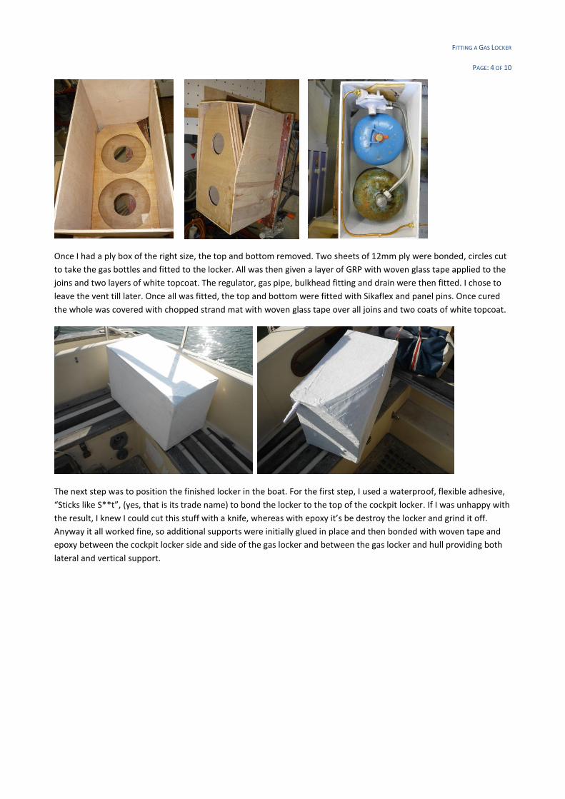
Once I had a ply box of the right size, the top and bottom removed. Two sheets of 12mm ply were bonded, circles cut
to take the gas bottles and fitted to the locker. All was then given a layer of GRP with woven glass tape applied to the
joins and two layers of white topcoat. The regulator, gas pipe, bulkhead fitting and drain were then fitted. I chose to
leave the vent till later. Once all was fitted, the top and bottom were fitted with Sikaflex and panel pins. Once cured
the whole was covered with chopped strand mat with woven glass tape over all joins and two coats of white topcoat.
The next step was to position the finished locker in the boat. For the first step, I used a waterproof, flexible adhesive,
“Sticks like S**t”, (yes, that is its trade name) to bond the locker to the top of the cockpit locker. If I was unhappy with
the result, I knew I could cut this stuff with a knife, whereas with epoxy it’s be destroy the locker and grind it off.
Anyway it all worked fine, so additional supports were initially glued in place and then bonded with woven tape and
epoxy between the cockpit locker side and side of the gas locker and between the gas locker and hull providing both
lateral and vertical support.

FITTING A GAS LOCKER
PAGE: 5 OF 10
Now we came to the first nerve racking bit – fitting the drain through the hull. You need to maintain a fall from the
locker to the skin fitting to ensure you don’t get water locking, so the skin fitting is inevitably only a few inches above
the water line and will almost certainly be submerged on starboard tack. To minimise the problem the skin fitting was
shortened as far as possible. This is one operation that wasn’t carried out with the boat afloat! But was done between
tides on the scrubbing posts. Remembering from dinghy sailing how little speed you need for self bailers to be
effective a standard vent cover was sikaflexed over the skin fitting to form a primitive self bailer – yet to be tested!!
While it could be fitted on the centre line, it would then be under water on both tacks and foul the kedge anchor
stowage.
Now we come to the second nerve racking bit – taking a jig saw to the cockpit seat. Since I was replacing al the teak
anyway, the first step was to remove all the old woodwork. The slats are screwed in place from below and the screw
heads glassed over, so it’s a brute force job to lever the teak off and then cut off the remaining screws and file flat.
With the gas locker glued in place it’s a blind cut, so definitely a case of measure twice and cut once!

FITTING A GAS LOCKER
PAGE: 6 OF 10
It’s a cosy fit, The vent runs up into the cubby hole in the cockpit coaming and the gas supply runs under the side deck,
into the galley food locker where there’s an emergency shut off and pressure test point.

FITTING A GAS LOCKER
PAGE: 7 OF 10
Teak locker tops
Don’t even think about doing this unless you have a lot of time and patience! If you have both, then it’s a rewarding
but expensive project and a great improvement. Buying sufficient teak strips ready planed from Robbins Timber will
set you back almost £1000 and the necessary Sika products another £400+. I was lucky and found someone selling
quarter sawn Burmese teak strips on eBay cut from old beams, so well seasoned. As I was able to provide a detailed
cutting list, which included a lot of short lengths, I got a good deal – it ended up that the adhesives and caulking cost
more than the timber!
With the boat afloat, it was not feasible to fit strip by strip, so I made 6mm ply templates for each section and built
the panels in the workshop over the winter. This reduced the time required to fit the panels on board, even so I had to
rework a couple of the edges. The templates were laid on a peg board and 10mm dowels and wedges used to hold the
outer strips in place during cutting and assembly. Once everything was a satisfactory fit, the panels were caulked with
Sika 290 DC, which also provides sufficient adhesion for them to be handled easily while maintaining some flexibility.
There are almost no right angles or straight lines anywhere, though typically it’s only a few degrees out – the section
forward of the cockpit locker for example was 88,89,91,92, but enough to not look right if you use a true right angle.
Tools required, in addition to normal woodworking hand tools :
a good mitre saw – I found the scale on mine is a degree out!
Router table and router, unless you plan to cut the rebates by hand
Moulding plane for rounded edges, or use the router
For more information, eMail questions to [email protected] or if you’re in Lymington come and have a
look.

FITTING A GAS LOCKER
PAGE: 8 OF 10

FITTING A GAS LOCKER
PAGE: 9 OF 10

FITTING A GAS LOCKER
PAGE: 10 OF 10
ADDITIONAL PHOTOGRAPHS
SUPPLIERS AND ADDITIONAL INFORMATION
Plywood : http://www.a1building.co.uk/
GRP : http://www.fibreglassdirect.co.uk/
Gas fittings : Mostly http://www.gasproducts.co.uk/ with test piece from http://www.leisureshopdirect.com/ and
saddles from http://www.chandleryworld.co.uk/
Sika products and general chandlery http://www.thechandler.co.uk/
If you would like any additional information about how to proceed with upgrades or repairs to your Contessa 32 an
excellent forum is available on the Association website where you can post questions and draw on the collective
knowledge of many owners.
Contessa 32 owners are in the very lucky position to be able to contact the original and current manufacturer of
Contessa yachts, the team at Jeremy Rogers Yachts are extremely helpful and will offer free advice to owners as well
as historical information about your particular Contessa. Jeremy Rogers Yachts can provide a range of spare parts and
will carry out repairs both small and large, their contact details can be found on the Jeremy Rogers website