fitting instructions ~ weld-in roll cages - safety devices devices weld-in roll... · fitting...
TRANSCRIPT
Fitting Instructions for Weld-in Roll Cages
Safety Devices International Ltd, Enterprise Court, Studlands Park Avenue, Newmarket, Suffolk. CB8 7EP Page 1 of 3 Tel: +44 (0) 1638 560524 Fax: +44 (0) 1638 560524 Email: [email protected] Web: www.safetydevices.com
Due to the many differing vehicles to which Safety Devices roll cages can be fitted, these instructions are of a general nature and not specific to your vehicle. Important Note Roll bars and/or front cages must not be fitted to any car with significant rusting of the bodyshell near where the bar will be welded down. For the main bar this usually applies to the rear wheel arches, base of centre pillars and adjacent floor or sills and to the floor toe-board or sills near the front door pillars for the front cage. Further, if the vehicle has ever suffered any accident damage, the bodyshell may be distorted and therefore may not fit the roll-over bar or front cage. It is usually easier to straighten the car than modify our bars! Slight floor damage is usually simply rectified before fitting starts.
Please read these instructions all the way through before starting, since the order of work is important. 1. Check all the components of the kit and review the layout drawing as to the position of each. 2. If still in place, remove from the car the following:
A. The front and rear seats.
B. The carpets, underfelt and rear wheel arch trim where the rear cage will stand.
C. All internal trim and roof lining.
D. The seat belts.
E. The dashboard.
F. Sun visors or interior mirrors.
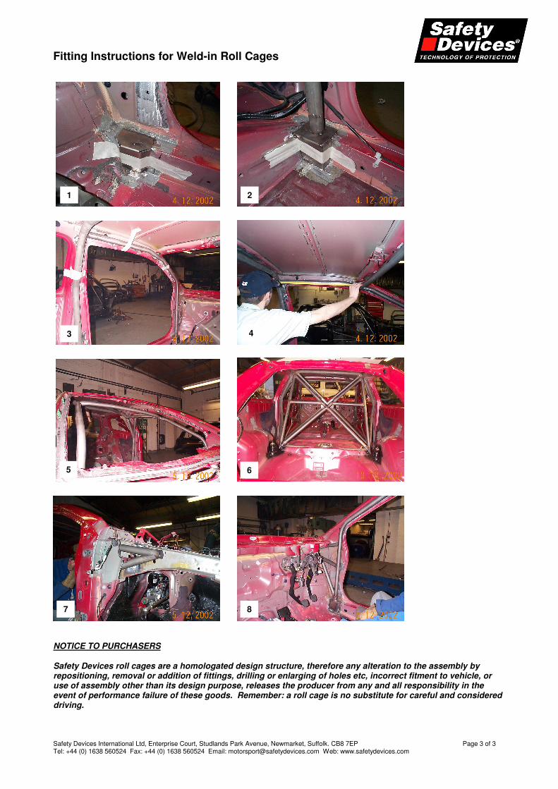
3. For safe welding to take place, disconnect the battery and empty the fuel tank or, if possible, remove the fuel tank. 4. Locate the ‘B’ post hoop (main hoop) floor plate loosely in position and hold it in place with a piece of tape (figure 1). This plate position must remain flexible until the main structure of the cage is finished. This plate position is the starting point of the original development and the starting point for installation. 5. The main hoop will require trimming to length. A black guideline is on each leg but the height of the hoop will have to be made in relation to each individual body shell. 6. Position the main hoop on the mounting plate, checking roof clearance etc. To hold the hoop in place, tape around the ‘B’ post to allow flexibility of movement (figure 2). 7. Loosely position the front leg plates and hold in place with tape. 8. Check the fit of the legs with the ‘B’ hoop and profile the legs to fit against the ’B’ hoop. Each leg has a guideline marked on it (at both ends) (figure 3).
9. The screen rail should now be positioned and the same profiling of tube ends carried out. If there is a roof diagonal in the kit, this must also be profiled and the whole assembly check fitted at the same time (figure 4). The fit and finish of this group of parts is paramount to the appearance of the cage. 10. Make sure:
A. The legs are close enough to the body to weld later and do not foul any other components.
B. The screen rail and roof diagonal are a good fit.
C. The link to the front triangulation is good and the welder can get to all joints easily (this only applies if front triangulation is being used)
11. Now you are ready to do the final welding of the main structure joints.
Fitting Instructions for Weld-in Roll Cages
Safety Devices International Ltd, Enterprise Court, Studlands Park Avenue, Newmarket, Suffolk. CB8 7EP Page 2 of 3 Tel: +44 (0) 1638 560524 Fax: +44 (0) 1638 560524 Email: [email protected] Web: www.safetydevices.com
12. Weld the joints as much as possible. 13. Remove the fitting plates from the ‘B’ post hoop and front legs. 14. Drop the cage down to the floor level. It may be necessary to pull the legs together with a rope or ratchet strap (figure 5). 15. Finish off the welding of the main structure on the topside of the joints. 16. Lift the cage back into position and relocate the foot plates 17. Shuffle the whole assembly to get the best fit in relation to the body. Tack the cage to the body to hold it in position.
DO NOT finalise the welding at this point. 18. Rear backstays and other straight points can now be positioned. Many have the ends already profiled but may require to be chamfered individually to get a perfect fit. Use a file or a die grinder to do this (figure 6). 19. Only when you have all the tubes tacked in place and are satisfied with the overall fit, do you finally weld all joints including the floor plates and gussets. 20. Use minimum weld lengths of 40mm when stitching to the body. Space them out accordingly and symmetrically. Remember, good quality, neat welding is very important. 21. Front triangulation: this usually requires a degree of skill in fitting the cage accurately. The triangulation will need to be in place prior to the front legs being finally positioned (figures 7 and 8). The illustrations are of a Rover 25 with the outer panel removed. Most cars’ triangulation is installed inside the engine compartment. 22. Always check the clearance to other components as you progress with the assembly. It is too late if, for example, you have finished the job and the seats foul.
SEE NEXT PAGE FOR PHOTOS
Fitting Instructions for Weld-in Roll Cages
Safety Devices International Ltd, Enterprise Court, Studlands Park Avenue, Newmarket, Suffolk. CB8 7EP Page 3 of 3 Tel: +44 (0) 1638 560524 Fax: +44 (0) 1638 560524 Email: [email protected] Web: www.safetydevices.com
NOTICE TO PURCHASERS Safety Devices roll cages are a homologated design structure, therefore any alteration to the assembly by repositioning, removal or addition of fittings, drilling or enlarging of holes etc, incorrect fitment to vehicle, or use of assembly other than its design purpose, releases the producer from any and all responsibility in the event of performance failure of these goods. Remember: a roll cage is no substitute for careful and considered driving.
1 2
3 4
5 6
7 8