fitting instructions zx6r 636 2013-2016 to be fitted by …
TRANSCRIPT

FITTING INSTRUCTIONSTO BE FITTED BY A QUALIFIED TECHNICIANZX6R 636 2013-2016
Secondary Alternator Cover Part No. EC-ZX6-2009-1-GBR / Secondary Clutch Cover Part No. EC-ZX6-2009-2-GBR /
Secondary Pulse Cover Part No. EC-ZX6-2007-3-GBR /
Bullet Frame Race Slider Set RACE - Part No. FS-ZX6-2009-R
Bobbin Set Part No. BA12-8-GBR-SET / Lower Chain Guard Part No. CGA09-GBR
THIS SHEET INCLUDES FITTING INSTRUCTIONS FOR THE FOLLOWING PARTS:
SECONDARY ALTERNATOR COVER PART NO. EC-ZX6-2009-1-GBR
www.GBRacing.eu
1 Remove lower fairing.2 Remove 4 existing bolts from the stock
Alternator cover, shown as position Bolt 1, 2 ,3 & 4.
3 Place the Secondary Alternator Cover over the stock cover.
4 Assemble 4 replacement bolts loosely in the correct position as shown.
5 Tighten bolts to a Torque of 11Nm as per manufacturers recommendations. DO NOT OVERTIGHTEN.
6 Re-Fit lower Fairing.
Bolt 3
Bolt 2
Bolt 1
Bolt 4
Bolt 1M6x35 - 11Nm
Bolt 2M6x35 - 11Nm
Bolt 3M6x35 - 11Nm
Bolt 4M6x35 - 11Nm
SECONDARY PULSE COVER PART NO. EC-ZX6-2007-3-GBR
1 Remove the Upper and Lower Fairings.2 Remove 4 existing bolts from the stock pulse
cover, shown as position Bolt 1, 2 ,3 & 4.3 Place the Secondary Pulse Cover over the
stock cover.4 Assemble 2 replacement M6x35, 1 replacement
M6x25 & 1 replacement M6x45 bolts, loosely in the correct position as shown.
5 Tighten bolts to a Torque of 11Nm as per Manufacturer’s recommendations. DO NOT OVERTIGHTEN.
6 Re-Fit the Fairings.
Bolt 3Bolt 4
Bolt 1M6x25 - 11Nm
Bolt 2M6x45 - 11Nm
Bolt 3M6x35 - 11Nm
Bolt 4M6x35 - 11Nm
Bolt 1
Bolt 2
SECONDARY CLUTCH COVER PART NO. EC-ZX6-2009-2-GBR
Bolt 2Bolt 1
Bolt 3
1 Remove lower fairing.2 Remove 4 existing bolts from the stock clutch
cover, shown as position Bolt 1, 2 ,3 & 4.3 Place the Secondary Clutch Cover over the
stock cover.4 Assemble 4 replacement M6x30 bolts, loosely
in the correct position as shown.5 Tighten bolts to a Torque of 11Nm as per
manufacturers recommendations. DO NOT OVERTIGHTEN.6 Re-Fit lower Fairing.
Bolt 1M6x30 - 11Nm
Bolt 2M6x30 - 11Nm
Bolt 3M6x30 - 11Nm
Bolt 4M6x30 - 11Nm
Bolt 4
FITTING INSTRUCTIONSTO BE FITTED BY A QUALIFIED TECHNICIAN
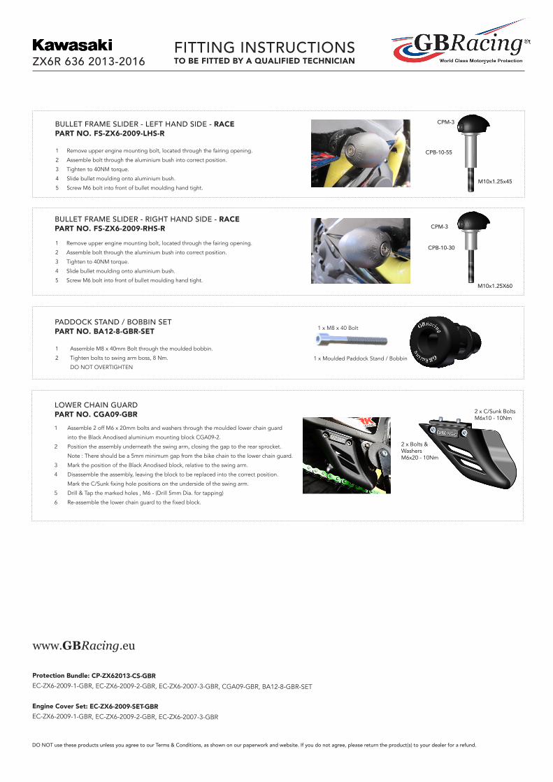
1 Assemble 2 off M6 x 20mm bolts and washers through the moulded lower chain guard
into the Black Anodised aluminium mounting block CGA09-2.
2 Position the assembly underneath the swing arm, closing the gap to the rear sprocket.
Note : There should be a 5mm minimum gap from the bike chain to the lower chain guard.
3 Mark the position of the Black Anodised block, relative to the swing arm.
4 Disassemble the assembly, leaving the block to be replaced into the correct position.
Mark the C/Sunk fixing hole positions on the underside of the swing arm.
5 Drill & Tap the marked holes , M6 - (Drill 5mm Dia. for tapping)
6 Re-assemble the lower chain guard to the fixed block.
LOWER CHAIN GUARD PART NO. CGA09-GBR
ZX6R 636 2013-2016
1 Remove upper engine mounting bolt, located through the fairing opening.
2 Assemble bolt through the aluminium bush into correct position.
3 Tighten to 40NM torque.
4 Slide bullet moulding onto aluminium bush.
5 Screw M6 bolt into front of bullet moulding hand tight.
BULLET FRAME SLIDER - RIGHT HAND SIDE - RACE PART NO. FS-ZX6-2009-RHS-R
CPB-10-30
M10x1.25X60
CPM-3
1 Remove upper engine mounting bolt, located through the fairing opening.
2 Assemble bolt through the aluminium bush into correct position.
3 Tighten to 40NM torque.
4 Slide bullet moulding onto aluminium bush.
5 Screw M6 bolt into front of bullet moulding hand tight.
BULLET FRAME SLIDER - LEFT HAND SIDE - RACEPART NO. FS-ZX6-2009-LHS-R
CPB-10-55
M10x1.25x45
CPM-3
2 x C/Sunk BoltsM6x10 - 10Nm
2 x Bolts & WashersM6x20 - 10Nm
Protection Bundle: CP-ZX62013-CS-GBREC-ZX6-2009-1-GBR, EC-ZX6-2009-2-GBR, EC-ZX6-2007-3-GBR, CGA09-GBR, BA12-8-GBR-SET
Engine Cover Set: EC-ZX6-2009-SET-GBREC-ZX6-2009-1-GBR, EC-ZX6-2009-2-GBR, EC-ZX6-2007-3-GBR
www.GBRacing.eu
DO NOT use these products unless you agree to our Terms & Conditions, as shown on our paperwork and website. If you do not agree, please return the product(s) to your dealer for a refund.
(1) Assemble M8 x 40mm Bolt thru moulded bobbin.
(2) Tighten bolts to swing arm boss , 8 N/m.
Do not overtighten.
Fitting Instructions
To be fitted by a qualified Technician
1 off M8 x 40 Bolts
1 off Moulded Paddock stand/bobbin
BA12-8-GBR
(1) Assemble M8 x 40mm Bolt thru moulded bobbin.
(2) Tighten bolts to swing arm boss , 8 N/m.
Do not overtighten.
Fitting Instructions
To be fitted by a qualified Technician
1 off M8 x 40 Bolts
1 off Moulded Paddock stand/bobbin
BA12-8-GBR
(1) Assemble M8 x 40mm Bolt thru moulded bobbin.
(2) Tighten bolts to swing arm boss , 8 N/m.
Do not overtighten.
Fitting Instructions
To be fitted by a qualified Technician
1 off M8 x 40 Bolts
1 off Moulded Paddock stand/bobbin
BA12-8-GBR
(1) Assemble M8 x 40mm Bolt thru moulded bobbin.
(2) Tighten bolts to swing arm boss , 8 N/m.
Do not overtighten.
Fitting Instructions
To be fitted by a qualified Technician
1 off M8 x 40 Bolts
1 off Moulded Paddock stand/bobbin
BA12-8-GBR
1 Assemble M8 x 40mm Bolt through the moulded bobbin.
2 Tighten bolts to swing arm boss, 8 Nm.
DO NOT OVERTIGHTEN
PADDOCK STAND / BOBBIN SET PART NO. BA12-8-GBR-SET
1 x Moulded Paddock Stand / Bobbin
1 x M8 x 40 Bolt