five star seal 80 series tm - flowserve · five star seal 80 series tm. 2 description the 86/87...
TRANSCRIPT
Installation Instructions
Experience In Motion
Dual, Cartridge Mounted,Flexible Stator Pusher SealDesigned for General ServiceApplications86 and 87
Five Star Seal 80 SeriesTM
2
Description
The 86/87 seals are cartridge mounted mechanical seals, designed for ease of installation and reliable operation. No seal setting dimensions are required. Rotatable centering tabs provide proper alignment. The flexible stator design compensates for inadvertent misalignment of the seal chamber face. Multiple springs provide uniform face loading and are external of the pumpage, resisting clogging or hang-up. Installation according to the following steps will assure long trouble free life of the 86/87 seals.
Equipment Check
1.1 Follow plant safety regulations: • lock out motor and valves. • wear designated personal safety equipment. • relieve any pressure in system. • consult plant MSDS files for hazardous material regulations.
1.2 Disassemble equipment to allow access to seal installation area.
1.3 Remove existing mechanical seal and gland or compression packing and packing gland.
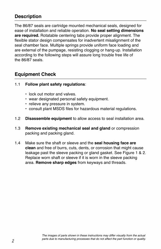
1.4 Make sure the shaft or sleeve and the seal housing face are clean and free of burrs, cuts, dents, or corrosion that might cause leakage past the sleeve packing or gland gasket. See Figure 1 & 2.
Replace worn shaft or sleeve if it is worn in the sleeve packing area. Remove sharp edges from keyways and threads.
The images of parts shown in these instructions may differ visually from the actual parts due to manufacturing processes that do not affect the part function or quality.
3
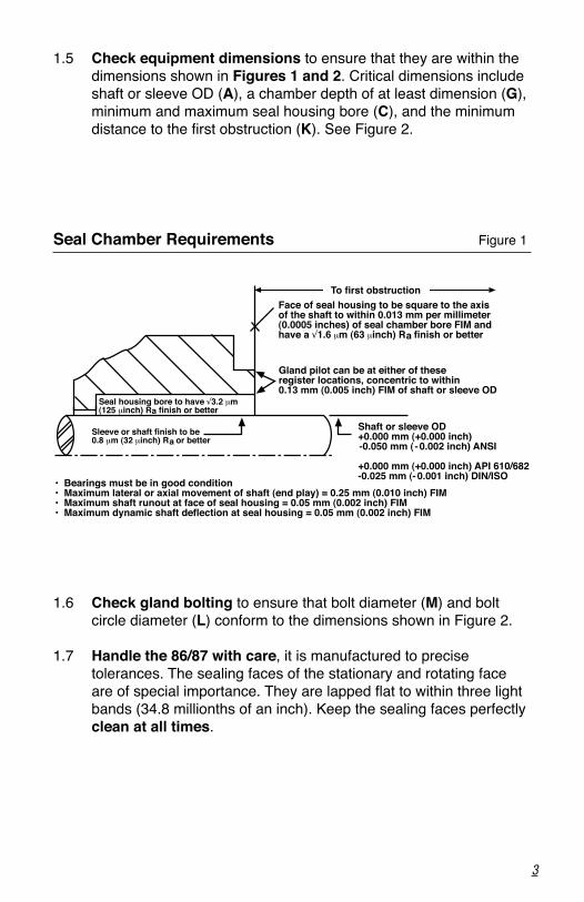
Seal Chamber Requirements Figure 1
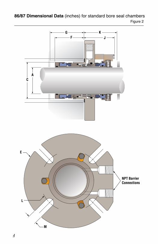
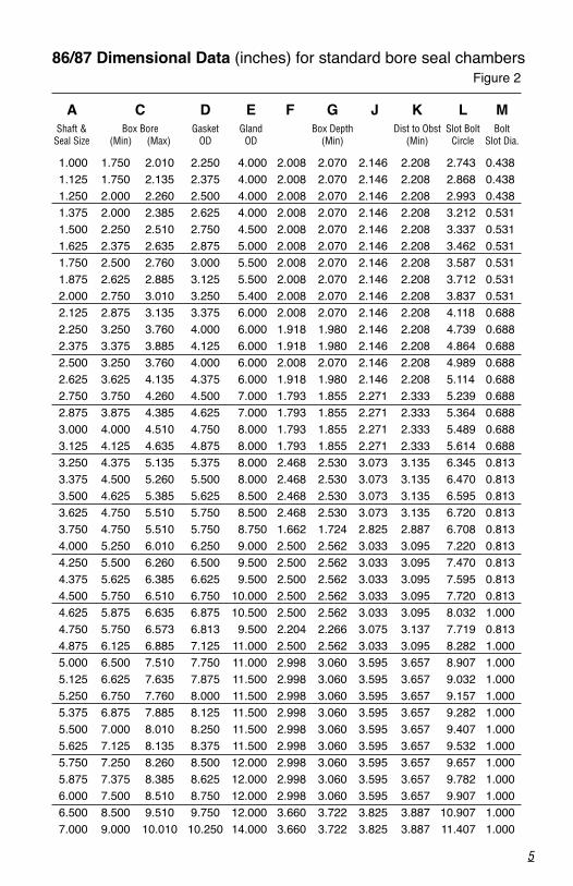
1.5 Check equipment dimensions to ensure that they are within the dimensions shown in Figures 1 and 2. Critical dimensions include shaft or sleeve OD (A), a chamber depth of at least dimension (G), minimum and maximum seal housing bore (C), and the minimum distance to the first obstruction (K). See Figure 2.
1.6 Check gland bolting to ensure that bolt diameter (M) and bolt circle diameter (L) conform to the dimensions shown in Figure 2.
1.7 Handle the 86/87 with care, it is manufactured to precise tolerances. The sealing faces of the stationary and rotating face are of special importance. They are lapped flat to within three light bands (34.8 millionths of an inch). Keep the sealing faces perfectly clean at all times.
To first obstructionFace of seal housing to be square to the axisof the shaft to within 0.013 mm per millimeter (0.0005 inches) of seal chamber bore FIM and have a √1.6 μm (63 μinch) R finish or bettera
Gland pilot can be at either of these register locations, concentric to within 0.13 mm (0.005 inch) FIM of shaft or sleeve OD
Seal housing bore to have √3.2 μm(125 μinch) R finish or better
Sleeve or shaft finish to be0.8 μm (32 μinch) R or better
a
aShaft or sleeve OD+0.000 mm (+0.000 inch)-0.050 mm ( -0.002 inch) ANSI
+0.000 mm (+0.000 inch) API 610/682-0.025 mm (- 0.001 inch) DIN/ISO• Bearings must be in good condition
• Maximum lateral or axial movement of shaft (end play) = 0.25 mm (0.010 inch) FIM• Maximum shaft runout at face of seal housing = 0.05 mm (0.002 inch) FIM• Maximum dynamic shaft deflection at seal housing = 0.05 mm (0.002 inch) FIM
4
86/87 Dimensional Data (inches) for standard bore seal chambers Figure 2
AC
GF
KJ
NPT BarrierConnections
E
L
M
5
1.000 1.750 2.010 2.250 4.000 2.008 2.070 2.146 2.208 2.743 0.438 1.125 1.750 2.135 2.375 4.000 2.008 2.070 2.146 2.208 2.868 0.438 1.250 2.000 2.260 2.500 4.000 2.008 2.070 2.146 2.208 2.993 0.438 1.375 2.000 2.385 2.625 4.000 2.008 2.070 2.146 2.208 3.212 0.531 1.500 2.250 2.510 2.750 4.500 2.008 2.070 2.146 2.208 3.337 0.531 1.625 2.375 2.635 2.875 5.000 2.008 2.070 2.146 2.208 3.462 0.531 1.750 2.500 2.760 3.000 5.500 2.008 2.070 2.146 2.208 3.587 0.531 1.875 2.625 2.885 3.125 5.500 2.008 2.070 2.146 2.208 3.712 0.531 2.000 2.750 3.010 3.250 5.400 2.008 2.070 2.146 2.208 3.837 0.531 2.125 2.875 3.135 3.375 6.000 2.008 2.070 2.146 2.208 4.118 0.688 2.250 3.250 3.760 4.000 6.000 1.918 1.980 2.146 2.208 4.739 0.688 2.375 3.375 3.885 4.125 6.000 1.918 1.980 2.146 2.208 4.864 0.688 2.500 3.250 3.760 4.000 6.000 2.008 2.070 2.146 2.208 4.989 0.688 2.625 3.625 4.135 4.375 6.000 1.918 1.980 2.146 2.208 5.114 0.688 2.750 3.750 4.260 4.500 7.000 1.793 1.855 2.271 2.333 5.239 0.688 2.875 3.875 4.385 4.625 7.000 1.793 1.855 2.271 2.333 5.364 0.688 3.000 4.000 4.510 4.750 8.000 1.793 1.855 2.271 2.333 5.489 0.688 3.125 4.125 4.635 4.875 8.000 1.793 1.855 2.271 2.333 5.614 0.688 3.250 4.375 5.135 5.375 8.000 2.468 2.530 3.073 3.135 6.345 0.813 3.375 4.500 5.260 5.500 8.000 2.468 2.530 3.073 3.135 6.470 0.813 3.500 4.625 5.385 5.625 8.500 2.468 2.530 3.073 3.135 6.595 0.813 3.625 4.750 5.510 5.750 8.500 2.468 2.530 3.073 3.135 6.720 0.813 3.750 4.750 5.510 5.750 8.750 1.662 1.724 2.825 2.887 6.708 0.813 4.000 5.250 6.010 6.250 9.000 2.500 2.562 3.033 3.095 7.220 0.813 4.250 5.500 6.260 6.500 9.500 2.500 2.562 3.033 3.095 7.470 0.813 4.375 5.625 6.385 6.625 9.500 2.500 2.562 3.033 3.095 7.595 0.813 4.500 5.750 6.510 6.750 10.000 2.500 2.562 3.033 3.095 7.720 0.813 4.625 5.875 6.635 6.875 10.500 2.500 2.562 3.033 3.095 8.032 1.000 4.750 5.750 6.573 6.813 9.500 2.204 2.266 3.075 3.137 7.719 0.813 4.875 6.125 6.885 7.125 11.000 2.500 2.562 3.033 3.095 8.282 1.000 5.000 6.500 7.510 7.750 11.000 2.998 3.060 3.595 3.657 8.907 1.000 5.125 6.625 7.635 7.875 11.500 2.998 3.060 3.595 3.657 9.032 1.000 5.250 6.750 7.760 8.000 11.500 2.998 3.060 3.595 3.657 9.157 1.000 5.375 6.875 7.885 8.125 11.500 2.998 3.060 3.595 3.657 9.282 1.000 5.500 7.000 8.010 8.250 11.500 2.998 3.060 3.595 3.657 9.407 1.000 5.625 7.125 8.135 8.375 11.500 2.998 3.060 3.595 3.657 9.532 1.000 5.750 7.250 8.260 8.500 12.000 2.998 3.060 3.595 3.657 9.657 1.000 5.875 7.375 8.385 8.625 12.000 2.998 3.060 3.595 3.657 9.782 1.000 6.000 7.500 8.510 8.750 12.000 2.998 3.060 3.595 3.657 9.907 1.000 6.500 8.500 9.510 9.750 12.000 3.660 3.722 3.825 3.887 10.907 1.000 7.000 9.000 10.010 10.250 14.000 3.660 3.722 3.825 3.887 11.407 1.000
A C D E F G J K L M Shaft & Box Bore Gasket Gland Box Depth Dist to Obst Slot Bolt Bolt Seal Size (Min) (Max) OD OD (Min) (Min) Circle Slot Dia.
86/87 Dimensional Data (inches) for standard bore seal chambers Figure 2
6
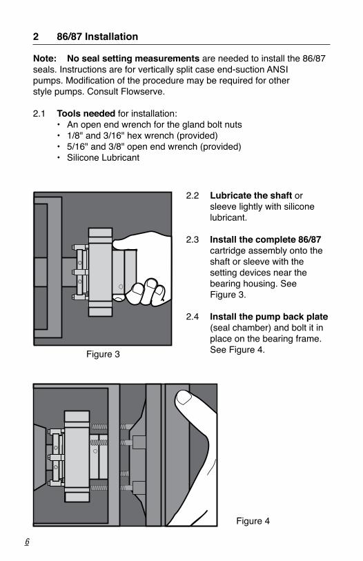
Note: No seal setting measurements are needed to install the 86/87 seals. Instructions are for vertically split case end-suction ANSI pumps. Modification of the procedure may be required for other style pumps. Consult Flowserve.
2.1 Tools needed for installation: • An open end wrench for the gland bolt nuts • 1/8" and 3/16" hex wrench (provided) • 5/16" and 3/8" open end wrench (provided) • Silicone Lubricant
2 86/87 Installation
2.2 Lubricate the shaft or sleeve lightly with silicone lubricant.
2.3 Install the complete 86/87
cartridge assembly onto the shaft or sleeve with the setting devices near the bearing housing. See Figure 3.
2.4 Install the pump back plate (seal chamber) and bolt it in place on the bearing frame. See Figure 4.Figure 3
Figure 4
7
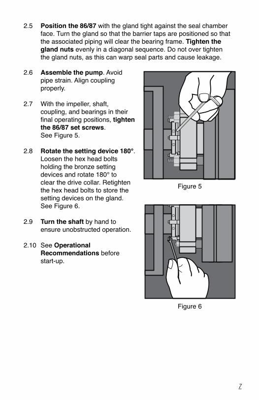
2.5 Position the 86/87 with the gland tight against the seal chamber face. Turn the gland so that the barrier taps are positioned so that the associated piping will clear the bearing frame. Tighten the gland nuts evenly in a diagonal sequence. Do not over tighten the gland nuts, as this can warp seal parts and cause leakage.
2.6 Assemble the pump. Avoid pipe strain. Align coupling properly.
2.7 With the impeller, shaft, coupling, and bearings in their final operating positions, tighten the 86/87 set screws. See Figure 5.
2.8 Rotate the setting device 180°. Loosen the hex head bolts holding the bronze setting devices and rotate 180° to clear the drive collar. Retighten the hex head bolts to store the setting devices on the gland. See Figure 6.
2.9 Turn the shaft by hand to ensure unobstructed operation.
2.10 See Operational Recommendations before start-up.
Figure 5
Figure 6
8
3 Piping
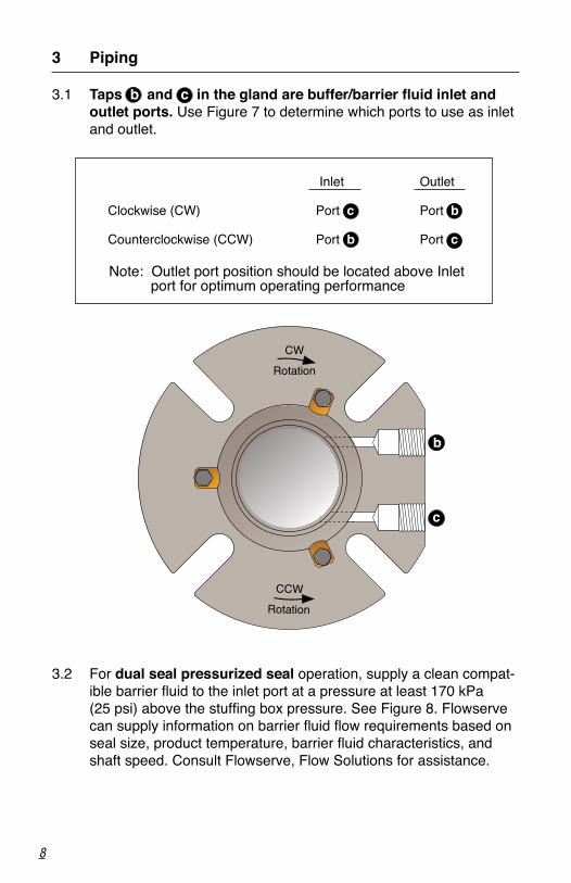
3.1 Taps b and c in the gland are buffer/barrier fluid inlet and outlet ports. Use Figure 7 to determine which ports to use as inlet and outlet.
3.2 For dual seal pressurized seal operation, supply a clean compat- ible barrier fluid to the inlet port at a pressure at least 170 kPa
(25 psi) above the stuffing box pressure. See Figure 8. Flowserve can supply information on barrier fluid flow requirements based on seal size, product temperature, barrier fluid characteristics, and shaft speed. Consult Flowserve, Flow Solutions for assistance.
Inlet Outlet
Clockwise (CW) Port c Port b
Counterclockwise (CCW) Port b Port c
CCW Rotation
CW
Rotation
b
c
Note: Outlet port position should be located above Inlet port for optimum operating performance
9
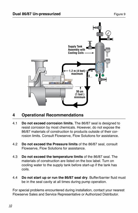
3.3 For dual seal un-pressurized operation, supply a clean compat-ible buffer fluid to the inlet port at a pressure below the stuffing box pressure. See Figure 9. Consult Flowserve, Flow Solutions for assistance. Flowserve can supply information on buffer fluid flow equirements based on seal size, product temperature, barrier fluid characteristics, and shaft speed.
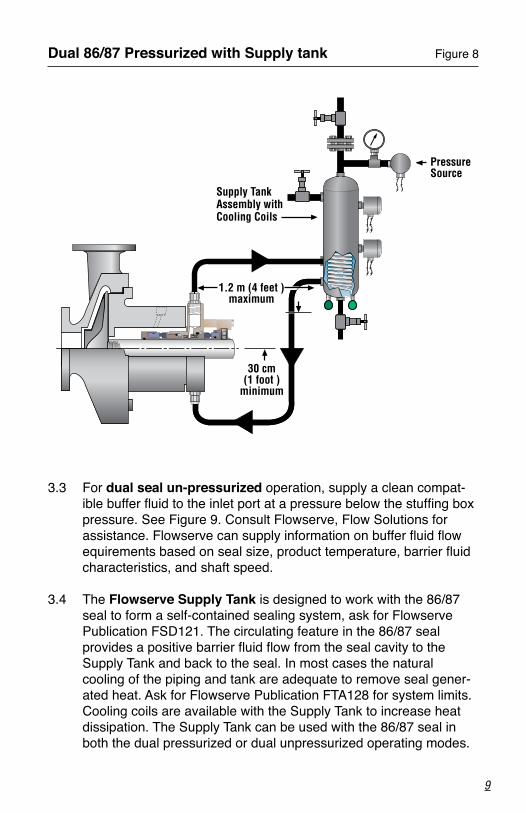
3.4 The Flowserve Supply Tank is designed to work with the 86/87 seal to form a self-contained sealing system, ask for Flowserve Publication FSD121. The circulating feature in the 86/87 seal provides a positive barrier fluid flow from the seal cavity to the Supply Tank and back to the seal. In most cases the natural cooling of the piping and tank are adequate to remove seal gener-ated heat. Ask for Flowserve Publication FTA128 for system limits. Cooling coils are available with the Supply Tank to increase heat dissipation. The Supply Tank can be used with the 86/87 seal in both the dual pressurized or dual unpressurized operating modes.
Dual 86/87 Pressurized with Supply tank Figure 8
1.2 m (4 feet )maximum
30 cm (1 foot )
minimum
Supply Tank Assembly with Cooling Coils
Pressure Source
10
Dual 86/87 Un-pressurized Figure 9
1.2 m (4 feet)maximum
30 cm(1 foot )
minimum
Supply Tank Assembly with Cooling Coils
4 Operational Recommendations
4.1 Do not exceed corrosion limits. The 86/87 seal is designed to resist corrosion by most chemicals. However, do not expose the 86/87 materials of construction to products outside of their cor-rosion limits. Consult Flowserve, Flow Solutions for assistance.
4.2 Do not exceed the Pressure limits of the 86/87 seal, consult
Flowserve, Flow Solutions for assistance.
4.3 Do not exceed the temperature limits of the 86/87 seal. The materials of construction are listed on the box label. Turn on cooling water to the supply tank before start-up if the tank has coils.
4.4 Do not start up or run the 86/87 seal dry. Buffer/barrier fluid must be in the seal cavity at all times during pump operation.
For special problems encountered during installation, contact your nearest Flowserve Sales and Service Representative or Authorized Distributor.
5 Repair
This product is a precision sealing device. The design and dimension tolerances are critical to seal performance. Only parts supplied by Flowserve should be used to repair a seal. To order replacement parts, refer to the part code and B/M number. A spare backup seal should be stocked to reduce repair time.
When seals are returned to Flowserve for repair, decontaminate the seal assembly and include an order marked "Repair or Replace." A signed certificate of decontamination must be attached. A Material Safety Data Sheet (MSDS) must be enclosed for any product that came in contact with the seal. The seal assembly will be inspected and, if repairable, it will be rebuilt, tested, and returned.
11
TO REORDER REFER TOB/M #F.O.
FIS152eng REV 11/12 Printed in USA
flowserve.com
To find your local Flowserve representativeand find out more about Flowserve Corporation, visit www.flowserve.com
Flowserve Corporation has established industry leadership in the design and manufacture of its products. When properly selected, this Flowserve product is designed to perform its intended function safely during its useful life. However, the purchaser or user of Flowserve products should be aware that Flowserve products might be used in numerous applications under a wide variety of industrial service conditions. Although Flowserve can provide general guidelines, it cannot provide specific data and warnings for all possible applications. The purchaser/user must therefore assume the ultimate responsibility for the proper sizing and selection, installation, operation, and maintenance of Flowserve products. The purchaser/user should read and understand the Installation Instructions included with the product, and train its employees and contractors in the safe use of Flowserve products in connection with the specific application.
While the information and specifications contained in this literature are believed to be accurate, they are supplied for informative purposes only and should not be considered certified or as a guarantee of satisfactory results by reliance thereon. Nothing contained herein is to be construed as a warranty or guarantee, express or implied, regarding any matter with respect to this product. Because Flowserve is continually improving and upgrading its product design, the specifications, dimensions and information contained herein are subject to change without notice. Should any question arise concerning these provisions, the purchaser/user should contact Flowserve Corporation at any one of its worldwide operations or offices.
© 2012 Flowserve Corporation
USA and Canada
Kalamazoo, Michigan USA
Telephone: 1 269 381 2650
Telefax: 1 269 382 8726
Europe, Middle East, Africa
Roosendaal, the Netherlands
Telephone: 31 165 581400
Telefax: 31 165 554590
Asia Pacific
Singapore
Telephone: 65 6544 6800
Telefax: 65 6214 0541
Latin America
Mexico City
Telephone: 52 55 5567 7170
Telefax: 52 55 5567 4224