fixed and base station fm receivers
TRANSCRIPT

7/28/2019 Fixed and Base Station FM Receivers
http://slidepdf.com/reader/full/fixed-and-base-station-fm-receivers 1/23
U.S. Department of Justice
National insti tute o f Justice
Fixed and
Base StationFM Receivers

7/28/2019 Fixed and Base Station FM Receivers
http://slidepdf.com/reader/full/fixed-and-base-station-fm-receivers 2/23
ABOUT THE TECHNOLOGY ASSESSMENT PROGRAM
Th e Technology Assessment Prog ram is sponsored by the Office of D evelopmen t, Testing, and Dissem-
ination o f the National Institute of Justice (NIJ), U.S. D epartm ent of Justice. The progr am responds to the
mandate of the Jus t ice Sys tem Improvement A ct of 1979, which created NIJ and directed it to encourage
research and developm ent to im prov e the criminal justice system and to disseminate :he results to Federal,
State, and local agencies.Th e Technology Assessment Prog ram is an applied researc 'l effo. that determines the technological
needs of justice sy stem agencies, sets minimum perfo rman ce standar ds for specific devices, tests commerciallyavailable equipm ent again st those standards, and disseminates the sta ndar ds and t he test results to criminal
justice agencies nationwide and internationally.
Th e program opera tes through:
T h e Tcci~nolo~glsscssmcnr Program Advisory Co~rtlcil T A P A C ) consisting of nationally recognized crim-inal justice pract itione rs from Fede ral, State , and local agencies, wh ich assesses technological needs and sets
priorities for research programs and items to be evaluated and tested.T h e Law Erlforccrncnt Standards Laboraton (L ES L) at the Natiorlal Bureau of Standards, w hich dev el-
op s volu ntary national perfo rman ce standard s for compliance testing to ensure that individual items of equip-
ment are suitable for use by criminal justice agencies. The standards are hased upon labor'ltory testing anii
evaluation of representative samples of each item of equipment t o determ ine the key attributes, develop testmethods, and establish minimum performance requirements for each essential attribute. In addition to the
highly technical standards, LE SL also produces user guides that explain in nontechnical te rm s the capabilities
of available equipment.T h e Tcc.iuloIog~1Asscsstncnt Program Itlformation Ccrltcr (TA PIC ), opera ted by a grantee . which super-
vises a national compliance testing program conducted by independent agencies. Th e standards developed b?
LESL wrve as performance benchmarks against which commercial equipment is measured. The facilities.
personnel, and testing capabilities of the independent laboratories ar e evaluated by L ES L prio r to testing each
item of equipment, and LESL helps the Information Center staff review and analyze data. Test results arepublished in Consumer Prod uct R eports designed to help justice system procurement officials make informed
purchasing decisions.Publications issued by the National Institute of Justice, including those of the Technology Assessment
Program, a re available from the National C riminal Justice Reference Service (NC JR S), which serves as acentral information and reference source for the Nation's criminal justice community. For further informa-
tion, or to register with NCJRS, write to the National Institute of Justice, National Criminal Justice
Reference Service, Washington, DC 10531.
Jmnes R. Stewart, Director.National Institute of Juqtice
The ,A\\~ \tun t Atlome! General. Ol ' fice o i Ju \ t icc P ro fram\ .
coord inare\ the act l \ i l~e\ l' the t 'o llouing profram Office\
an d Bureau\: National In\r itu~ c f Jubtice. Bureau o f J u t i c eStari\tic\. Burc;tu ol' Justice .A\si\tance. O ffice of J u v e n ~ l c
Ju5t1ce ~ n dDelinqucnc? Prevention. and Officc for Victims
ol' C r ~ n ~ c .

7/28/2019 Fixed and Base Station FM Receivers
http://slidepdf.com/reader/full/fixed-and-base-station-fm-receivers 3/23
U.S. Department of Justice
National Institute of Justice
Technology Assessment Program
Fixed and Base Station FM Receivers
NI Standard-0206.01
Supersedes NILECJ-STD-0206.00 dated September 1975
July 1988

7/28/2019 Fixed and Base Station FM Receivers
http://slidepdf.com/reader/full/fixed-and-base-station-fm-receivers 4/23
U.S. DEPARTMENT OF JUSTICE
National Institute of Justice
James K. Stewart, Dlrector
SupersedesNILECJSTD4206.00dated September 1975.
ACKNOWLEDGMENTS
Thit standard w u formulated by the Law Entorcement Standards Laboratory of the National Bureau of Standards under thedirection of Marshall J. T r d o , Program M anager for Communications Systems, and Lawrence K. Eliason, Chief of LESL.NBSElectromagnetic Fields Division staff members responsible for the prepamtion of th e standard were R amon L. Jesch and Arthur E.Wainright Acknowledgment is given to previous work in this field by the Associated Public-Safety Com munications Ofl7cers. Inc. andthe Elec tronic Indus tr ies W i n t i o n . This tandard has been reviewed and approved by the Techno logy Assessment Program A dvisoryCouncil.
The echnical effort to develo p this standard was conducted under Interagency Agreem ent LEAA-J-IAA 421-3, Project No. 8504.

7/28/2019 Fixed and Base Station FM Receivers
http://slidepdf.com/reader/full/fixed-and-base-station-fm-receivers 5/23
This docum ent, N IJ Standard-0206.01, Fixed and Base Station FM R eceivers , is an equipment standarddeveloped by the L aw Enforcement Standards Laboratory of th e National Bureau of Standards. It is pro-duced as part of the Technology Assessment Program of the National Institute of Justice (NIJ). A briefdescription of the prog ram appears on the inside front cover.
This standa rd is a technical document th at specifies perform ance and oth er requ irements equipmentshould m eet to satisfy th e needs of criminal justice agencies for high quality service. Purchase rs can use th etest methods described in this standard to determine whether a particular piece of equipment meets theessential requirements, or they may h ave th e tests conducted o n their behalf by a qualified testing laboratory.Procu reme nt officials may also refer to this standard in their purchasing documents and require that equip-ment offered for purchase meet the requirements. Compliance with the requirements of the standard may beattested to by an independent laboratory or guaranteed by the vendor.
Because the N IJ s tandard is designed as a procure men t aid, it is necessarily highly technical. Fo r thosewho seek general guidance concerning the selection and application of law enforcement equipment, userguides have also been published. The guides explain in nontechnical language how to select equipmentcapable of performance required by an agency.
NIJ standards are subjected to continuing review. Tech nical comments and recommended revisions arewelcome. Please send suggestions to th e Prog ram M anager fo r Standards, National Institute of Justice, U.S.Department of Justice, Washington, DC 20531.
Before citing this or any other N IJ standard in a con tract document, users should verify that t he mostrecent edition of the standard is used. Write to: Chief, Law Enforc emen t Stand ards Labo ratory, NationalBureau of Standards, Gaithersburg, MD 20899.
Lester D. ShubinProgram M anager for StandardsNational Institute of Justice
7/28/2019 Fixed and Base Station FM Receivers
http://slidepdf.com/reader/full/fixed-and-base-station-fm-receivers 6/23
NIJ STANDARDFOR
FIXED AND BASE STATION
FM RECEIVERS
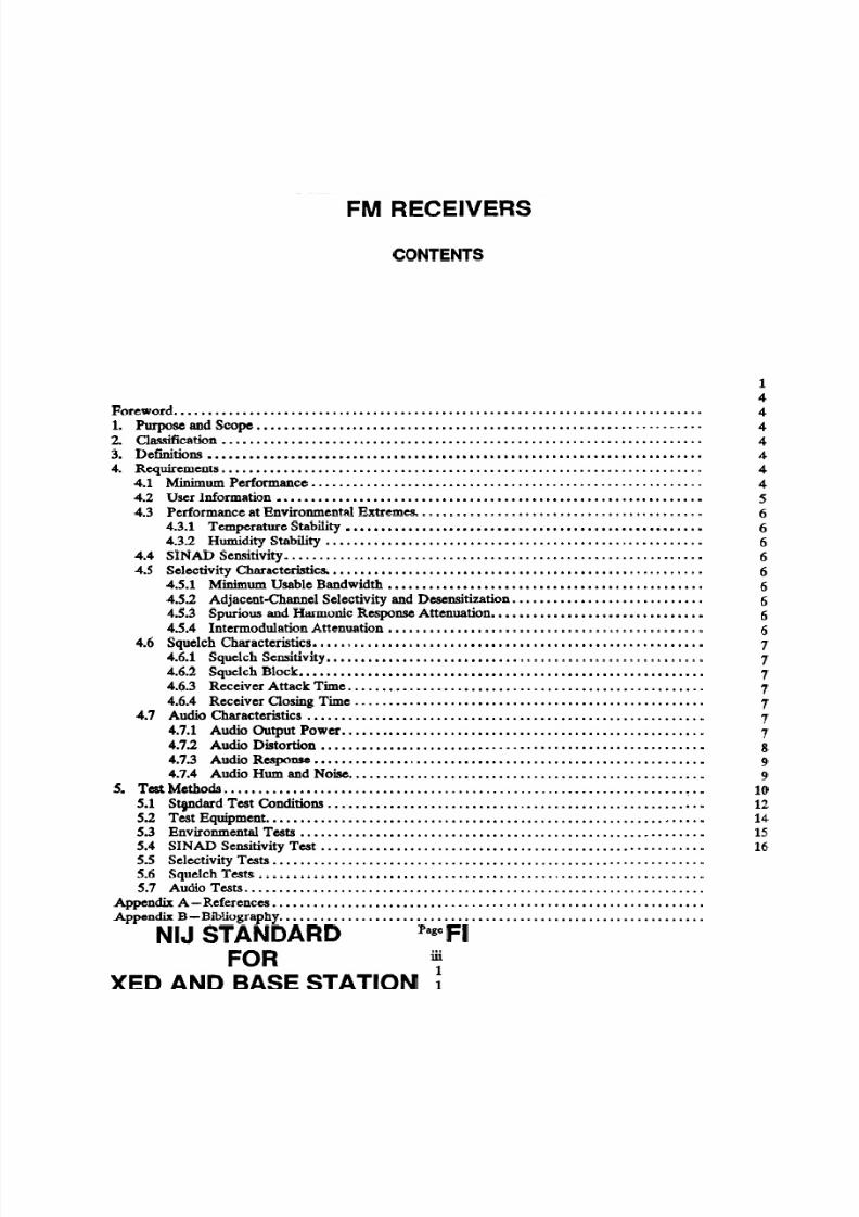
CONTENTS
Foreword.............................................................................1 Purpose and Scope .................................................................2. Classification ..............................................................................................................................................Definitions
4. Requirements................................................................................................................................1 Minimum Performance...............................................................2 User Information ..........................................3 Performance at Environmental Extremes.....................................................3.1 Temperature Stability
4.3.2 Humidity Stability .....................................................................................................................4 SINAD Sensitivity
4.5 Selectivity Characteristics.. .....................................................4.5.1 Minimum Usable Bandwidth ..............................................4.5.2 Adjacent-chamel Selectivity and Desensitization ............................4.5.3 Spurious and Harmonic Response Attenuation...............................4.5.4 Intermodulation Attenuation ..............................................
4.6 Squelch Characteristics.........................................................4.6.1 Squelch Sensitivity...................................................................................................................6.2 Squelch Block
4.6.3 Receiver Attack Time........................................................................................................6.4 Receiver Closing Time...........................................................7 Audio Characteristics
4.7.1 Audio Output Powa ....................................................4.7.2 Audio Distortion ........................................................4.7.3 Audio Response .........................................................4.7.4 Audio Hum and Noise ........................................................................................................................ Test Methods ........................................................1 Stpdard Test Conditions
5.2 Test Equipment................................................................5.3 Environmental Tests ...........................................................5.4 SINAD Sensitivity Test ........................................................5.5 Selectivity Tests ...............................................................5.6 Squelch Tests .....................................................................................................................................7 Audio Tests
Appendix A- eferences...............................................................Appendix B -Bibliography ..............................................................
Page
iii
1114
4
4
4
4
4
4
5
6
6
66
6
6
6
6
6
7
7
7
7
7
7
78
9
9
10
12
14
15
16

7/28/2019 Fixed and Base Station FM Receivers
http://slidepdf.com/reader/full/fixed-and-base-station-fm-receivers 7/23
COMMONLY USED SYMBOLS AND ABBREVIATIONS
A
acAMcdcmC P
CISdd Bd c"C
"Fd i memf
eqFfc
fig-FMft
f t1s
g
ggr
amperealternating currentamplitude modulationcandelacentimeterchemically pur ecycle per second
da ydecibeldirect currentdegree Celsiusdegree Fahrenheitdiameter
electromotive forceequationfaradfootcandlefigurefrequency modulationfoot
foot per secondacceleration
gramgrain
Hhhf
Hzi.d.inirJ
L
L
IbIbfIbf-inImIn
logM
rn
minmm
mp hm lsNN-m
henryhourhigh frequency
hert i (cls)inside diam eterinchinfraredjoulelambertliter
poundpound-forcepound-force inchlumenlogarithm (natural)logarithm (common)molarmeterminutemillimeter
mile per hourmeter per secondnewtonnewton meter
nmNo.0.d.nP.Pa
PePPPPm9tradrfrh
sSDsec.SWR
uhf
UV
vvhfW
Xwt
ar ea =u nit 2 (e.g., ft2, in2, etc.); vol um e= un ie (e.g., ft3, m3, etc.)
PREFIXES
d deci (lo-')c centi (lo-')m mil li ( W 3 )p, micro
n nano (10-4p pic0 (10-12)
da deka (10)
h hecto (I@k kilo (I d )M mega (lo6)
G giga (109)T tera (1e2)
COMMON CONVERSIONS
(See ASTM E380)
lb x 0.4535924=kgIbf x 4.448222 =NIbfl ftx 14.59390= N /mIbfminx 0.1129848=N-mIbf/in2x 6894.757 =P amph x 1.609344= km /hqt x 0.9463529=L
nanometernumberoutside diameterohm
pagepascalprobable error
Pagespart per million
q-tradianradio frequencyrelative humiditysecondstandard deviationsectionstanding wave radioultrahigh frequencyultravioletvoltvery high frequencywattwavelengthweight
Temperature: (T.F - 2)x 519= T-c
Temperature: (Tec X 9/5)+ 32=FF

7/28/2019 Fixed and Base Station FM Receivers
http://slidepdf.com/reader/full/fixed-and-base-station-fm-receivers 8/23
NIJ STANDARDFOR
FIXED AND BASE STATION
FM RECEIVERS
1. PURPOSE AND SCOPE
The purpose of this document is to establish performance requirements and methods of test for non-trunked, ftequency modulated (FM) fixed and base station receivers used by law enforcement agencies. Thisstandard applies to voice-modulated nonrnultiplex receivers which either do not have special subsystems suchas selective signaling or voice privacy, or in which such subsystems are bypassed or disabled during testingfor compliance with this standard. This standard supersedes NILECJSTD-0206.00, Fixed and Base Station
F M Receivers, dated September 1975.This revision has been written to include receivers operating in the806-866 MHz frequency band and it also provides modified requirements for receiver sensitivity, audioresponse and closing time. The tests have been revised to accommodate receivers with a balanced audiooutput and updated to incorporate improved tests of spurious and harmonic response attenuation and inter-modulation attenuation.
2. CLASSIFICATION
For the purpose of this standard, fixed and base station FM receivers are classified by their operatingfrequencies.
2.1 Type 1
Receivers which operate in the 25-50 MHz band with a receiver channel spacing of 20 kHz.
2.2 Type II
Receivers which operate in the 150-174MHz and with a receiver channel spacing of 30 kHz.
2.3 Type Ill
Receivers which operate in the 400-512 MHz band with a receiver channel spacing of 25 kHz.
2.4 Type IV
Receivers which operate in the 806-866 MHz band with a receiver channel spacing of 25 kHz.
3. DEFINITIONS
The principal terms used in this document are defined in this section. Additional definitions relating tolaw enforcement communications are given in LESP-RPT-0203.00, Technical Terms and Definitions Usedwith Law Enforcement Communications Equipment [I]'.
3.1 Adjacent-Channel Selectivity and Desensitization
The ability of a receiver to discriminate against a signal at the frequency of an adjacent channel.
'Numbers in brackets refer to the references in appendix A.
1

7/28/2019 Fixed and Base Station FM Receivers
http://slidepdf.com/reader/full/fixed-and-base-station-fm-receivers 9/23
3.2 AM Hum and Noise
Th e residual amplitude modulation present o n an unmodulated carrier.
3.3 Audio Harmonic Distortion
Nonlinear distortion characterized by the appearance in the output -1 integral multiples of an audiofre-quency input signal.
3.4 Audio Hum and Noise Power
Th e av erage audiofrequency powe r dissipated in a load across the o utput terminals of a receiver havingan unmodulated radio frequency (rf) signal input.
3.5 Audio Noise Output Power
Th e avera ge audiofrequency power dissipated in a load across the output terminals of an unsquelchedreceiver having no rf signal input.
3.6 Audio Output Power
The audiofrequency power dissipated in a load across the receiver output terminals of an unsquelchedreceiver having a mo dulated rf signal input.
3.7 Audio Response
Th e variation in the output of a receiver as a function of audiofrequenc y within a specified bandw idth.
3.8 Authorized Bandwidth
T he maximum w idth of the band of frequencies specified by th e Federal Com munications Comm ission tobe occu pied by an emission, i.e., 20 kHz for public safety agencies [2].
3.9 lntermodulation Attenuation
The ratio expressed in decibels, of (1) the level of specified signals that produces an intermodulationresponse under specified conditions to (2) the receiver's SINAD sensitivity.
3.10 lntermodulation Response
The response resulting from the mixing of two or more frequencies, in the nonlinear elements of a
receiver, in which a resultant frequency is generated that falls within the ra nge of frequencies passed by thereceiver.
3.1 1 Maxlmum Squelch Posltlon
T he adjustment of th e squelch control of a receiver to th e least sensitive condition.
3.12 Minimum Usable Bandwidth
Th e frequency displacement from the unmodulated carrier frequency, +3 kHz, of an input test signalwhich is 6 dB above the 12-dB SINAD sensitivity voltage and w hich p roduces a 12-dB SINAD ratio.
3.13 Noise Quieting
T he red uction of receiver aud io noise output caused by th e presence of an incoming rf signal.
3.14 Nominal Value
The numerical value of a device characteristic as specified by the manu facturer.

7/28/2019 Fixed and Base Station FM Receivers
http://slidepdf.com/reader/full/fixed-and-base-station-fm-receivers 10/23
3.1 5 Rated System Deviatlon
The maximum carrier frequency deviation permitted by the FCC. For law enforcement communications
systems, it is k 5 kHz.
3.1 6 Receive Mode
The condition of a receiver when unsquelched and receiving information.
3.1 7 Receiver Attack Time
The time required to produce a specified audio output power level upon application of a specified rf
input signal, when the squelch control is in the threshold squelch position.
3.18 Receiver Closing Time
The time required to reduce a specified audio output power to a designated level upon removal of the rf
input signal, when the squelch control is in the threshold squelch position.
3.19 Sampler
A series device which couples energy over a broad frequency range from a transmission line into a third
port. The attenuated output signal from the third port has the same waveform as the original signal.
3.20 Selectivity
The extent to which a receiver is capable of differentiating between the desired signal and signals at other
frequencies, some of which may differ only slightly from the desired signal.
3.21 SINAD Ratio
The ratio, expressed in decibels, of (1) signal plus noise plus distortion to (2) noise plus distortion
produced at the output of a receiver; from SIgnal NoiseAnd Distortion R atio.
3.22 SINAD Sensitivity
Theminimum modulated rf signal input level required to produce a specified SINAD ratio at a specified
audio output power level.
3.23 Spurlous and Harmonlc Response
The output of a receiver causedby a signal at a frequency other than that to which the receiver is tuned.
3.24 Squelch
A circuit function for preventing a receiver from producing audio output power in the absence of an rf
input signal.
3.25 Squelch Block
A squdched condition resulting from excessive frequency deviation due to a specifiedrf modulated input
signal level.
3.26 Standlng Wave Ratio (SWR)
The ratio of the maximum to the minimum amplitudes of the voltage or current appearing along a
transmission line with a constant input source.

7/28/2019 Fixed and Base Station FM Receivers
http://slidepdf.com/reader/full/fixed-and-base-station-fm-receivers 11/23
3.27 Threshold Squelch Position
The adjustment of the squelch control, starting from the maximum unsquelched position, that firstreduces the audio noise output power by a specified amount.
3.28 Threshold Squelch Sensitivity
T he minimum standard modulated rf signal input level required to unsquelch a receiver whe n the squelch
control is in the threshold squelch position.
3.29 Tight Squelch Sensitivity
The minimum standard mod ulated rf signal input level required to unsquelch a receiver whe n the squelchcontrol is in the maximum squelch position.
4. REQUIREMENTS
4.1 Minimum Performance
Th e receiver performance shall meet or exceed the requirement for each characteristic as given belowand in table 1. The performance requirements meet or exceed those given in the Rules and Regulationspublished by the FCC [2].
4.2 User Information
A nominal value for each of the characteristics listed in table 1 shall be included in the informationsupplied to th e purchaser by the m anufacturer or distributor. In addition, the manufacturer shall provide therange of temp eratures within w hich the receiver is designed t o be o perated, the receiver operating frequen-cies, the receiver audio o utput impedance, and the standard supply voltage.
4.3 Performance at Environmental Extremes
The ability of the receiver to operate in environmental extremes shall be determined using the testmethods described in paragraph 5.3. It is suggested that these tests be performed before the transceiver istested for compliance with the requirements of paragraphs 4.4 through 4.7.
4.3.1 Temperature Stablllty
Low temperature tests shall be conducted at -30 OC (- 22 O F ) or the lowest temperature at which themanufacturer s tates (sec. 4.2) that th e unit will operate properly, whichever is lower, and high temperaturetests shall be conducted at 60 OC (140 OF) or the highest temperature at w hich the manufacturer states that theunit will operate properly, whichever is higher.
When th e receiver is operated a t low and high temperatures, as defined above, its performance shall notvary, w ith respect to the ap propriate values in table 1 items A through U), more than items V through AB,
for th e characteristics listed. In addition, the receiver audio distortion at an audio output pow er of 5 W shallbe less than 9 percent (item AC) for an rf signal with standard m odulation.
4.3.2 Humldlty Stablllty
After the receiver h as been maintained'at 50 OC (122 OF) and 90 percent relative humidity or greater forat least 8 hours, its performance shall not vary, with respect to the appropriate values in table 1 (items Athrough U), more than items AD through AJ, or th e charac teristics listed. In addition, the rece iver audiodistortion at an audio output power of 5 W shall be less than 9 percent (item AK) for an rf signal withstandard modulation.
4.4 SlNAD Sensitivity
When measured in accordance with paragrap h 5.4, the SINAD sensitivity of th e receive r shall be 0.4 p V
(item A) o r less at a SINAD ratio of 12 dB and an audio output power of at least 50 percent of 5W, i.e.,

7/28/2019 Fixed and Base Station FM Receivers
http://slidepdf.com/reader/full/fixed-and-base-station-fm-receivers 12/23
TABLE1. Minimumperformance requirementsforF e d and bare station FM CM~VCTS.
Minimum requirement requency band
25-50 150-174 400-512 806-866
S d v i t y C ha ra eic rid csA SINAD SensitivityB. SINAD Sensitivity Variance
(Supply Voltage Varied *lo%)
SdadradrviryhamderictierC. Minimum Usable Bandwidth +5 kHz *5 kHz +5 kHz *5 kHz
D. Adjacent-Channel Selectivityand Desensitization 85dB 85 dB 85dB 80dB
E. Spurious and Harmonic ResponseAttenuation 95dB 95 dB 95dB 85dB
F. Intermodulation Attenuation 70dB 75 dB 80dB 65dB
Squelch Charade&tics
G. Threshold Squelch SensitivityH. Tight Squelch SensitivityL Threshold Squelch Sensitivity Variance
(Supply Voltage Varied *10%)J. Squelch BlockK. Receiver Anack TimeL. Receiver Closing Time
Audio CharaderidcsM. Audio Output Power (Loudspeaker)N. Audio Output Power (Earphones)
0. Audio Output Power (Telephone Line)P. Audio Output Power Variance
(Supply Voltage Varied A 10%)
Q. Audio DistortionR Audio Response (Loudspeaker)S. Audio Response (Earphones and
Telephone Line)T. Audio Hum and Noise (Unsquelched)U. Audio Hum and Noise (Squelched)
Temperature Stability
V. SINAD SensitivityW. Minimum Usable BandwidthX Adjacent-Channel Selectivity
and DesensitizationY. Tight Squelch Sensitivity2 Thrmhold Squelch Sed tivlt yM Audio Output Power
AB. Audlo Hum and N o hAC. Audlo Distortion
0.2 p v
25 kHz150ms
150ms
0.3 pV2 5 kHz150ms
150ms
0.3 pV+5 kHz150ms
150ms
0.3 pV*5 kHz
150ms
150ms
Humidity StabUityAD. SINAD SensitivityAE. Minimum Usable BandwidthAF. Adjacent-Channel Selectivity
and DesensitizationAG. Tight Squelch Sensitivity
AH. Threshold Squelch SensitivityAL Audio Output PowerAJ. Audio Hum and NoiseAK. Audio Distortion
2.5 W. When the standard power supply voltage is varied +.10 percent, the SINAD sensitivity shall be 0.4
pV (item B) or less.
The selectivity characteristics of minimum usable bandwidth, adjacent-channel selectivity and desensi-
tization, spurious and harmonic response attenuation, and intermodulation attenuation shall be measured in

7/28/2019 Fixed and Base Station FM Receivers
http://slidepdf.com/reader/full/fixed-and-base-station-fm-receivers 13/23
accordance with paragraph 5.5.
4.5.1 Mlnlmum Usable Bandwidth
The minimum usable bandwidth of the receiver shall be no less than 2 5 kHz (item C) for an applied rf
signal 6 dB above the measured 12-dB SINAD sensitivity value.
4.5.2 Adjacent-Channel Selecthrlty and Desensltlzatlon
The adjacentchannel selectivity and desensitization of the receiver shall be item D or more for a degra-dation of an on-channel signal from 12-dB SINAD ratio to 6-dB SINAD ratio caused by an adjacent-channel
signal.
4.5.3 Spurlous and Harmonlc Response Attenuation
The spurious and harmonic response attenuation of type I, I1 and I11 receivers shall be 95 dB (itemE) or
more as compared to the on-channel 20-dB noisequieting signal voltage for responses of the receiver between
the lowest intermediate frequency of the receiver and at least twice the receiver operating frequency, or 1000
MHz, whichever is higher. For type IV receivers, the spurious and harmonic response shall be 85 dB (itemE)
or more as compared to the standard SINAD signal voltage for responses of the receiver between the lowest
intermediate frequency of the receiver and at least twice the receiver operating frequency.
4.5.4 lntermodulatlon Attenuatlon
The intermodulation attenuation of type I, I1 and I11 receivers shall be item F or more for a degradation
of an on-channel signal from 12-dB SINAD ratio to 6dB SINAD ratio by two relatively strong signals
located at one and two channel spacings, respectively, from the receiver frequency, both signals being at
frequencies either above or below the on-channel signal. For type IV receivers, the intermodulation attenua-
tion shall be 65 dB (item F) or more for a degradation of an on-channel signal from the 12-dB SINAD ratio
plus 3 dB excess to the 12 dB SINAD ratio by two relatively strong signals located at one and two channel
spacings, respectively, from the receiver frequency, both signals being at frequencies either above or below
the on-channel signal.
4.6 Squelch Characteristics
The squelch characteristicsof sensitivity, block, receiver attack time and receiver release time shall
be measured in accordance with paragraph 5.6.
4.6.1 Squelch Senslthrlty
The threshold squelch sensitivityof the receiver shdl be item O or less. The tight squelch sensitivity
&all be 2.5 pV (item H) r less. When the standard power supply voltage is varied + 10 percent and - 0
percent, the threshold squelch sensitivity shall be item I or less.
4.6.2 Squelch Block
The receiver shall not squelch for modulation frequencies of 0.3 to 3 kHz when the squelch control
is adjusted to the maximum squelch position and the frequency deviation of the input signal is 2 5 kHz (item
J) or less.
4.6.3 Recelver Attack Tlme
The eceiver attack time for the receiver to produce an audio output power of 90 percent of 5 W, i.e., 4.5
W, shall be 150 ms (item K) or less.
4.6.4 Recelver Closing Tlme
The receiver closing time for the audio output power of the receiver to decrease to 10 percent of 5 W,
ie., 0.5 W, shall be 150 ms (item L) or less.

7/28/2019 Fixed and Base Station FM Receivers
http://slidepdf.com/reader/full/fixed-and-base-station-fm-receivers 14/23
4.7 Audlo Characterlstlcs
Th e audio ch aracteristics of output power, distortion, response, and hum and noise shall be m easured inaccordance with paragraph 5.7.
4.7.1 Audlo Output Power
The audio output power of the receiver shall be at least 5 W (item M) if a loudspeaker is used at th ereceiver output, a t least 3 mW (item N) if earphone s are used, and 12 mW (item 0)f a telephone line is used.When the standard supply voltage is varied +10 percent and - 0 percent, the audio output power shall notbe reduced mo re than 0.1 dB (item P) below 5 W.
4.79 Audlo DIstortlon
Audio distortion at audio output pow ers of 5 W and 3 mW shall be less than 5 percent (item Q) for an rfinput signal with standard modulation.
4.7.3 Audlo Response
T he audio response of the receiver, when used with a loudspeaker, shall be within - , +2.d B (item R)
of an ideal 6 dB p er o ctave deem phasis curv e with constant frequency deviation at frequencies between 0.3and 3 kHz, w ith the exception that a . dditional 6 dB per octav e roll-off may be present from 600 to 300 Hz.
When used with earphones or telephone line, the audio response of th e receiver shall also be w ithin-
,+1dB (item S) of the same curve a t frequencies between 0.3 and 3 kHz, with th e exception that a 6 dB per octave
roll-off from 600 to 300 Hz may be present.
4.7.4 Audlo Hum and Nolse
Th e audio hum and noise output power from the receiver in the unsquelched condition shall be 45 dB(item T) or m ore, and in th e maximum sq uelched condition shall be 60 dB (item U) or m ore below an audiooutput power of 5 W.
5. TEST METHODS
5.1Standard Test Conditions
Allow all measurement equipment to warm up until the system has achieved sufficient stability to per-form t he m easurement. Unless otherwise specified, perform all measu remen ts under standard test co nditions.
5.1.1 Standard Temperature
Standard ambient temperature shall be between 20 and 30 "C (68 and 86 OF).
5.1.2 Standard Relathre Humldlty
Standard ambient relative humidity shall be between 10 and 85 percent.
5.1.3 Standard Power Supply Voltage
Th e standard supply voltage shall be 120 V, 60 Hz , unless otherwise stated by th e manufacturer. Variableauto transformers or tapped transformers may be used to adjust the supply voltage to the required value,which should be m easured at the receiver pow er supply input terminals, if practicable, and adjusted to within1percent of the nominal value.
5.1.4 Standard Test Frequencies
The standard receiver test frequency shall be the receiver operating frequencies specified in section 4.2.

7/28/2019 Fixed and Base Station FM Receivers
http://slidepdf.com/reader/full/fixed-and-base-station-fm-receivers 15/23
5.1.5 Standard Audlo Test Modulatlon
Stan dard au dio test m odulation shall be a 1-lcHz signal (from a source with distortion less than 1percent)at the level required to produce 60 percent of rated system deviation (i.e., 2 3 kHz).
5.1.6 Standard Squelch Adjustment
Th e squelch co ntrol shall be adjusted t o the maximum unsquelch position for all receiver measurementsexcept wh ere otherw ise specified.
5.1.7 Standard Duty Cycle
Th e standard duty cy cle shall be continuous operation in the receive mode.
5.2 Test Equipment
The test equipment discussed in this section is limited to that equipment which is the most critical inmaking the m easurem ents discussed in this standard. All other test equipm ent shall be of co mp arabl e quality.
5.2.1 FM Slgnal Generator
Th e F M signal generator shall have a 50-fl output impedance, a maximum SW R of 1.2 and a calibratedvariable outp ut level acc urate to 22 dB when terminated in a 5 0 4 oad. It shall also have a single sideband
1-Hz bandwidth phase noise less than - 135 dB below the carrier at 25-kHz eparation for carrier frequenciesof 500 MHz and lower (- 130 dB at 900 MHz). Th e generator should include a digital frequency counterhaving an uncertainty no grea ter than one part in lo6, and a deviation monitor or calibrated control fo rdetermining the peak frequency deviation with an uncertainty no greater than 5 percent. If an integralfrequency counter is not included, a separate frequency counter having th e required accuracy shall be pro-vided. Thre e such generators are required.
5.2.2 CW Sweep Slgnal Generator
The CW sweep signal generator shall have the same characteristics as the F M signal generator exceptthat the FM capability and the low phase noise capability are not required. Th e sweep generator should havesome means of slowly, automatically sweeping the frequency band, especially for t he higher frequencies.
59.3 Dlstortlon Analyzer
Th e distortion analyzer shall have a required input level of between 1and 5 V rms, an input impedanceof at least 50,000 f l shunted by less than 100 p F and an accuracy of a t least +1 dB. It shall have th e capabilityto m easure both audio distortion and the rms voltage of audio signals to w ithin 2 3 percent. The analyzershall incorporate a 1000-Hz band elimination filter for the audio distortion measurements.
Th e isolation transformer shall have a turns ratio of 1 o 1, an mpedance of 600a,a frequency responsewithin k 0 .1 dB from at least 300 to 3000 Hz, and a power handling capability of 20 dBm. The isolationtransformer is needed w hen th e receiver audio output does not h ave an isolating circuit such as an outputtransformer o r capacitor and th e following measuring instrumen t (e.g., distortion analyzer) has a single-endedinput.
5.2.5 Standard Audlo Output Load
The standard audio output load shall be either the actual speaker or an impedance equivalent to thenominal impedance of the receiver speaker with a power rating equal to or exceeding the nominal audiooutput power of th e receiver. A filter network shall not be used between th e audio output terminals and theaudio output load. If an external monitor speaker is used, a matching netw ork to maintain the standa rd outputload impedance a t the audio output terminals shall be provided.
59.6 Standard RF Input Load
Th e standard rf input load shall consist of a shielded 5 0 4 resistor whose SW R is less than 1.05.

7/28/2019 Fixed and Base Station FM Receivers
http://slidepdf.com/reader/full/fixed-and-base-station-fm-receivers 16/23
A signal combiner shall be used when two or more signal generators are connected to the receiver undertest. Its amplitude imbalance shall be no greater than 0.2 dB, its SWR shall be no greater than 1.3 and theisolation between input terminals shall be aminimum of 30 dB. A variety of multiport devices may be used assignal combiners including power dividers, directional couplers, and hybrid junctions.
5.2.8 Audio Voltmeter
The audio voltmeter shall measure rms voltage to an uncertainty of1 percent or less.
52.9 Chart Recorder
The chart recorder shall have sufficient speed of response to record spurious receiver responses when thesignal generator is swept slowly.
5.2.10 Devlatlon Meter
The deviation meter shall be capable of measuring the peak deviation of a modulating waveform with anuncertainty no greater than 5 percent of the deviation being monitored.
52.1 1 Environmental Chamber
The environmental chamber shall produce air temperatures from -30 to 60 "C ( - 2 2 to 140 OF) andrelative humidities in the range of 90 to 95 percent. The test item shall be shielded from air currents blowingdirectly from heating or cooling elements in the chamber. The temperature of the test item shall be measuredwith a thermometer separate from the sensor used to control the chamberair temperature. Likewise, humidityshall be measured with a hygrometer separate from the sensor used to control humidity.
5.3 Environmental Tests
The environmental tests shall be performed using standard supply voltage and the measurement tech-niques described in sections5.4 through 5.7.
5.3.1 Temperature Test
Place the receiver, with the power turned off and all covers in place, in the environmental chamber.Adjust the chamber to the required low temperature t "C (+3.6 OF). Allow the receiver to reach tempera-ture equilibrium and maintain it at this temperature for30 minutes. With the receiver still in this environment,connect it to the standard power supply and operate it at the receiver standard duty cycle. Fifteen minutesafter turn-on, test the receiver to determine whether it meets the requirements of paragraph4.3.1.Repeat theabove procedure at the required high temperature *2 "C 23.6OF).
6.3.2 Humldlty Teat
Place the receiver, with power turned off and all covers in place,in the environmental chamber. Adjustthe relative humidity to aminimum of 90 percent at 50 "C (122 OF) or more and maintain the receiver at theseconditions for at least 8 hours. With the receiver still in this environment, connect it to the standard supplyvoltage and operate it at the receiver standard duty cycle. Fifteen minutes after turn-on, test the receiver todetermine whether it meets the requirements of section4.3.2.
5.4 SlNAD Sensitivity Test
Connect the receiver and test equipment as shown in figure1 for those receivers with a balanced audiooutput. For those receivers with an unbalanced audio output, the isolation iransformer is not required. Set thesquelch control to the standard squelch adjustment. Adjust the FM signal generator to the standard testfrequency with standard audio test modulation. Set the generator for 1-mV output and the receiver volumecontrol for an audio output power of 5 W. Do not readjust the volume control for the remainder of themeasurement. Decrease the output level of the generator until the SINAD ratio of the receiver is12 dB, asdetermined with the distortion analyzer. Measure the audio output power to make certain it is at least2.5 W

7/28/2019 Fixed and Base Station FM Receivers
http://slidepdf.com/reader/full/fixed-and-base-station-fm-receivers 17/23
and record t he g enerator output voltage for convenience in resetting to a 12-dB SI NA D ratio, as required bysome of the following tests. Repeat for changes in standard supply voltage of +10 percent and - 10 percent.
5.5 Selectivity Tests
5.5.1 Mlnlmum Usable BandwldthTest
Connect th e receiver and test equipment as shown in figure 1, with c.r without t he isolation transformer,as necessary. Adjust the receiver and FM signal generator in accordance with section 5.4 until a 12-dBSINA D ratio is reached. W ith the generator still set for standard audio test modulation, increase the genera-tor rf output by 6 dB. Adjust th e frequency of the generator above the test frequency until the 12-dB SIN ADsignal ratio is again obtained. Record the generator frequency. Repeat this measurement by adjusting thegenerator frequency below the test frequency and record t he gen erator frequency. Th e smaller displacementfrom the test frequency +3 kHz (standard test modulation deviation) is the receiver bandwidth.
FIGURE. Block diagram for SINAD sensitiv@, mminimumusable banddh , sqrrclch sensitiviiy, squelch block,
and audio disturtion measunments.
5.5.2 Adjacent-Channel Selecthrlty and Desensltlzatlon Test
DistortionAnalyzer
b
FM SignalGenerator
Connect the receive r and test equipment as shown in figure 2. W ith the output of gene rator No. 2 set tozero, adjust the rec eiver and signal generator No. 1 n accordance with section 5.4 until a 12-dB SIN AD ratiois reached. Adjust signal generator No. 2 for 3-kHz frequency deviation at 400 Hz, and se t it to a frequencycorresponding t o th e center of the next higher adjacent channel. Th en adjust the outp ut of signal generatorNo. 2 to produce a 6-dB SIN AD ratio with both signals present. T he ratio, in decibels, of th e output voltageof signal generator No. 2 to that of signal generator No. 1 s the adjacent-channel selectivity for th e upperchannel. Repeat th e above proced ure for the next lower adjacent channel. The smaller of the tw o ratios is th erequired measurement.
FIGURE BlocJc diagramfor ad jamz tdmmeI seIectl'vity and dcnnritircrtion, and spuriau and h a d eqxm~e
nttenuarion measurementsfor type IV receiwrs.
-
FM SignalGenerator
No. 1
5.5.3 Spiirlous and Harmonl~ esponse Attentuatlon Tests
b .
+
5.5.3.1 Type 4 IZ, and III Receivers
.
Connect the receiver and test equipment as shown in figure 3. Adjust the CW signal generator to thestandard test frequency. With the gene rator adjusted for zero output, adjust the receiver volume con trol toproduce 1.25 W. The output power is entirely noise power. Do not readjust the volume control for the
Receiver
Under Test -
I
IsolationTransformer
I
-
SlgnalComblner
b
StandardAudio Output
Load
' d
ReceiverUnder Test: A
FM Signal
--,
-Standard
Audlo OutputLoad
GeneratorNo . 2
- rolatlonTransformer
- lstortlonAnalyzer

7/28/2019 Fixed and Base Station FM Receivers
http://slidepdf.com/reader/full/fixed-and-base-station-fm-receivers 18/23
remainder of the measurement. Increase the output of the generator until the audio noise output power of the
receiver is decreased by 20 dB, i.e., 20 dB of noise quieting. Note the generator output in decibels above one
microvolt (dBkV) at this frequency. Then increase the output of the generator to approximately 0.1 V, and
slowly vary the generator frequency continuously from just below the lowest intermediate frequency of the
receiver to at least twice the receiver operating frequency or 1000 MHz, whichever is higher. Synthesized
receivers preclude easy prediction of spurious response frequencies. Note each frequency that produces a
rczeiver response as indicated by noise quieting in the receiver's audio output. Ignore harmonic frequencies
of the generator that fall within the channel to which the receiver is tuned. For large frequency bandwidths,
use a signal generator that can be swept automatically and a chart recorder or voltmeter as an automaticmeans of recording receiver response as a function of frequency, as this sweep may take many hours. Then go
back and measure the response at each frequency recorded. For each response, adjust the generator output to
produce 20 dBof noise quieting. Record the generator output in dBp+V.The generator output at the spurious
response frequencyminus he generator output at the standard test frequencyis the spurious response attenu-
ation. Repeat for all spurious responses. The smallest attenuation is the value sought.
FIGURE. BIOck diagram for spuriacs and harmonicmpmm a t t e n u ah measutwnentfbr ope I , ZZand ZZZ cceiven
5.5.3.2 TypeN eceivers
Connect the receiver and test equipment as shown in figure 2. With the output of FM signal generator
No. 2 set to zero, adjust the receiver and signal generator No. 1 n accordance with section5.4 until a 12-dB
SINAD ratio isreached. Note the generator output in dBpV. Increase the signal level of signal generator No.
1by 3 dB. Adjust signal generator No. 2 for 3 kHz requency deviation at 400 Hz. Then increase the output
of signal generator No. 2 to approximately0.1 V and slowly vary the generator frequency continuously from
just below the lowest intermediate frequency of the receiver to at least twice the receiver operating fre-
quency. For large frequency bandwidths, use a signal generator that can be swept automatically and a chart
recorder or voltmeteras an automatic means of recording receiver responseasa function of frequency, as thissweep may take many hours. Then go back and measure the response at each frequency recorded. At the
frequency of each spurious response, change the level of signal generator No. 2 until the standard SINAD is
obtained at the receiver output terminals. Record the frequency of the unwanted input signal along with its
~ B F Vevel at the input of the receiver. The ratio, in decibels, of the output voltage of signal generator No.
2 to that of signal generator No. 1 at the 12-dB SINAD ratio is the value sought. Repeat for all spurious
responses. The smallest attenuation is the value sought.
IsolationTransformer
-
5.6.4 lntermodulatlon Attenuatlon Tests
+
AF Voltmeteror
Power Meter
CW SignalGenerator
5.5.4.1 5 p e I , 11, and.111 Receivers
-
Connect the receiver and test equipment as shown in figure 4. With the output levels of signal generators
Nos.2
and 3 set to zero, adjust the receiver and FM signal generator No.1
n accordance with section 5.4until a 12dB SINAD ratio is reached. Adjust unmodulated generator No. 2 to the center frequency of the
next higher Adjacent channel. Adjust generator No. 3 for 3 kHz frequency deviation at 400 Hz, and set it to
the center frequency of the second higher adjacent channel, ie., two channels above the standard test fre-
quency. Then adjust the output levels of generators Nos. 2 and 3 to produce a 6-dE SINAD ratio with $1
three signals present. Maintain generators Nos. 2 and 3 at equal output voltages throughout the measurement.
Adjust slightly the frequency of generator No. 3 to obtain the 6-dB SINAD ratio with the minimum signal
levels from the generators Nos. 2 and 3. The ratio, in decibels, of the output voltage of generator No. 2 (or
3) to that of generator No. 1 s the intermodulation attenuation for the upper channels. Repeat the aboveprocedure for the lower two adjacent channels, with generator No. 3 set to the lowest channel. The smaller
of the two ratios is the value sought.
- ReceiverUnder Test
StandardAudio Output
Load
-

7/28/2019 Fixed and Base Station FM Receivers
http://slidepdf.com/reader/full/fixed-and-base-station-fm-receivers 19/23
FIGURE . Black diagrwn for intermodulation anmuation measurement.
FM SlgnalGenerator
No. 1rn
5.5.4.2 TypeN eceivers
.
Connect the receiver and test equipment as shown in figure 4. With the output levels of FM signal
generators Nos. 2 and 3 set to zero, adjust the receiver and FM signal generator No. 1 n accordance with
section 5.4 until a 12-dB SINAD ratio is reached. Increase the signal level of signal generator No. 1by 3 dB.
Adjust m o dul a ted generator No. 2 to the center frequency of the next higher adjacent channel. Adjust
mo du la te d generator No. 3 to the center frequency of the second higher adjacent channel, i.e., two chan-nels above the standard test frequency. Incrementally increase the levels of signal generators Nos. 2 and 3
until the S INAD of the receiver under test is degraded to the 12-dB SINAD ratio. Maximize this degradation
by adjusting the frequency of either signal generator No. 2 or No. 3. Maintain generator Nos. 2 and 3 at equal
output voltages throughout the measurement. The ratio, in decibels, of the output voltage of generator No. 2
(or 3) to that of the 12-dB SINAD ratio of the receiver is the intermodulation attenuation for the upper
channels. Repeat the above procedure for the lower two adjacent channels, with generator No. 3 set to the
lowest channel. The smaller of the two ratios is the value sought.
5.6 Squelch Tests
5.6.1 Squelch Senslthrlty Tests
FM SignalGenerator
No . 22
Connect the receiver and test equipment as shown in figure 1with or without the isolation transformer,
as necessary. Adjust the receiver and FM signal generator in accordance with section 5.4 until a 12-dB
SINAD ratio is reached. Set the output level of the generator to zero, and measure the audio noise output
power. Slowly adjust the squelch control until the audio noise output power drops abruptly (40 dB or more).
Do not adjust the squelch control any further. This is the threshold squelch position. Increase the output level
of the signal generator until the measured audio output power is within 10 dB of 5 W. Th e signal generator
output voltage is the value for threshold squelch sensitivity. Repeat using + 10 percent and - 10 percent
standard supply voltages.
Repeat the above procedure with the squelch control in the maximum squelch position. The resultant
signal generator output voltage is the value for tight squelch sensitivity.
-
5.6.2 Squelch Block Test
SignalCombiner
,
Connect the receiver and test equipment as shown in figure 1. Adjust the receiver and FM signal
generator in accordance with section 5.4 to give 5 W of audio output power. Set the output level of the signalgenerator to zero, and measure the audio noise output power. Then set the squelch control to the maximum
squelch position. Adjust the output level of the generator to 12 dB above the measured value of the receiver's
tight squelch sensitivity voltage. Then increase the frequency deviation of the generator until the audio
output power drops abruptly (40 dB or more). Repeat the above procedure with modulation frequencies of
0.3, 0.5, 2.5, and 3 kHz. The frequency deviations of the signal generator modulation are the values for
squelch block.
- eceiverUnder Test
*
k
FM SignalGenerator
No. 3
-Standard
Audio OutputLoad
DistortionAnalyzer
- IsolationTransformer
-

7/28/2019 Fixed and Base Station FM Receivers
http://slidepdf.com/reader/full/fixed-and-base-station-fm-receivers 20/23
5.6.3 Recdver Attack Tlme Teat
Connect the equipment as shown in figure 5a. Open and close the SPST switch to trigger the oscillo-
scope trace. Connect the dc output of the coaxial diode detector to the vertical input of the oscilloscope and
adjust the horizontal centering controls so that the start of the detector output begins at the left graticule of
the oscilloscope screen. Do not adjust the oscilloscope trigger or centering controls any further.
FIGUREa. BIock diagram for setting osdlhcope trigger.
# .StandardRF lnput
,--elay
Load CoaxialDiode
Detector
Connect the receiver and test equipment as shown in figure 5b.With the SPST switch closed, adjust the
FM signal generator in accordance with section 5.4 until the 12-dB SINAD ratio is reached with an output
of 5W. Set the signal generator to zero, and measure the audio noise output power. Slowly adjust the squelch
control until the audio output power drops abruptly (40dB or more). Do not adjust the squelch any further.
Adjust the generator output level to 12 dB above the measured value of the receiver threshold squelch
sensitivity voltage. With the oscilloscope on recurrent sweep, adjust the oscilloscope vertical controls for full
scale deflection. Do not adjust the trigger. Return the oscilloscope to external trigger and open and then close
the SPST switch and photograph the trace. The time required for the sweep to travel from the left side of the
oscilloscope graticule until the audio output power level reaches 4.5 W is the value for receiver attack time.
FM SignalGenerator
IDC Power
0 b 1supply SPST
Switch
Oscilloscope
Verticalinput
Trigger
Input
FIGUREb. BIG& diagram for receiver attack ti me and receiver ch dn g tune meanrrements.
* >
StandardRF lnput
AF Voltmeteror
Power MeterJ
Loadw
t
ReceiverUnder Test
~scilloscope
VerticalO lnput
Triggerlnput
FM Signal IGenerator -
solationTransformer
IDC Power I
O ISupply
SPST
Switch
StandardAudio Output
Load
-

7/28/2019 Fixed and Base Station FM Receivers
http://slidepdf.com/reader/full/fixed-and-base-station-fm-receivers 21/23
5.6.4 Recehrer Closlng Tlme Teat
Connect equipment as shown in figure 5a. Adjust the oscitloscope so the output from the diode coaxial
detector stops at the left graticule of the oscilloscope when the SPST switch is opened. Interconnect the
receiver and test equipment as shown in figure 5b. Adjust all equipment as in 5.6.3. Open the SPST switch
and photograph the display. The time required for the sweep to travel from the left graticule of the oscillo-
scope until the audio output power level falls to 500 mW is the value of receiver closing time.
5.7 Audio Tests5.7.1 Audlo Output Power Test
Connect the receiver and test equipment as shown in figure 6 with or without the isolation transformer,
as necessary. Modulate the FM signal generator with standard audio test modulation and set it to the standard
test frequency. With the signal generator adjusted for 1-mV output, set the receiver volume control to the
maximum position, and measure the audio output power. Repeat using +10 percent and - 10 percent stan-
dard supply voltages.
RGURE. Block diagram for audio outputpower, audio mpmq and audio hum and noisemeasurements.
5.79 Audlo Dlstortlon Test
A F Voltmeteror
Power Meter..
Connect the receiver and test equipment as shown in figure 1.Modulate the FM signal generator with
standard audio test modulation and set it t o the standard test frequency. With the signal generator adjusted for
I-mV output, adjust the receiver volume control for an audio output power of 5 W and measure the audio
distortion. Repeat at an audio output power of 3 mW for earphones and 12 mW for telephone lines.
-
5.7.3 Audlo Response Test
Connect the receiver and test equipment as shown in figure 6. Modulate the FM signal generator with
standard audio test modulation and set it t o the standard test frequency. With the signal generator adjusted for
1-mV output, adjust the receiver volume control for an audio output power of 5 W. D o not readjust the
volume control for the remainder of the measurement. Reduce the generator frequency deviation to 1kHz,
and measure the audio output power. Repeat for modulating frequencies of 0.3,0.5,2 and 3 kHz. Compute the
ratio, in decibels, of each of these latter power levels relative to the output power at 1-kHz modulation.
.Standard
Audio OutputLoad
+
5.7.4 Audlo Hum and Nolse Tests
FMSignal
Generator
-
Connect the receiver and test equipment as shown in figure 6. Modulate the FM signal generator with
standard audio test modulation and set it to the standard test frequency. With the signal generator adjusted for
1-mV output, adjust the receiver volume control for an audio output power of 5 W. Do not readjust the
volume control for the remainder of the measurement. Remove the modulation from the signal generator and
measure the audio hum and noise output power. Compute the ratio, in decibels, of the audio output power to
the audio hum and noise output power. This is the value for audio hum and noise (unsquelched).
Set the squelch control to its maximum squelch positioa. Set the output level of the generator to zero and
measure the audio hum and noise output power. Calculate the ratio, in decibels, of the audio output power to
the audio hum and noise output power. This is the value for audio hum and noise (squelched).
- Receiver
Under Test
Isolation
TransformerJ
-

7/28/2019 Fixed and Base Station FM Receivers
http://slidepdf.com/reader/full/fixed-and-base-station-fm-receivers 22/23
APPENDIX A- REFERENCES
[I] Greene, F. M. Technical terms and defiaitions used w ith law enforcement commuaications equipment.LESP-RPT-0203.00. National Institute of Justice, U.S. Department of Justice, Washington, DC
20531; 1973 June.
[2 ] Land mobile radio serv ices. Rules and Regulations. Vol . 5, Part 90. Federal C ommunications Commis-sion. Governm ent Printing O ffice, Washington, D C 20402.

7/28/2019 Fixed and Base Station FM Receivers
http://slidepdf.com/reader/full/fixed-and-base-station-fm-receivers 23/23
APPENDIX B- BIBLIOGRAPH Y
Continuous-recording voice-logging tape recorders. NIJ Standard-0220.00. National Institute of Justice, U.S.
Department of Justice, Washington, DC 20531; 1983 July.
Fixed and base station antennas. NIJ Standard-0204.01. National Institute of Justice, U.S. Department of
Justice, Washington, DC 20531; 1981 December.
Fixed and base station FM transmitters. NIJ Standard-0201.01. National Institute of Justice, Washington, DC
20531; 1987 September.
Minimum standards for communication antennas. Part I-Base or fixed station antennas. EIA Standard RS-329-A; 1975 December.
Minimum standards for land mobile communication FM or PM receivers, 25-947 MHz. EIA Standard RS-
204-C; 1982 January.
Mobile stations FM or PM radiotelephone transceivers operating in certain VHFIUHF bands in the fie-
quency range 27-23 MHz to 470 MHz with RF power output rating not exceeding 10 watts. Canada
Dept. of Communications Standard RSS 121.