fixed displacement gear pumps -...
TRANSCRIPT
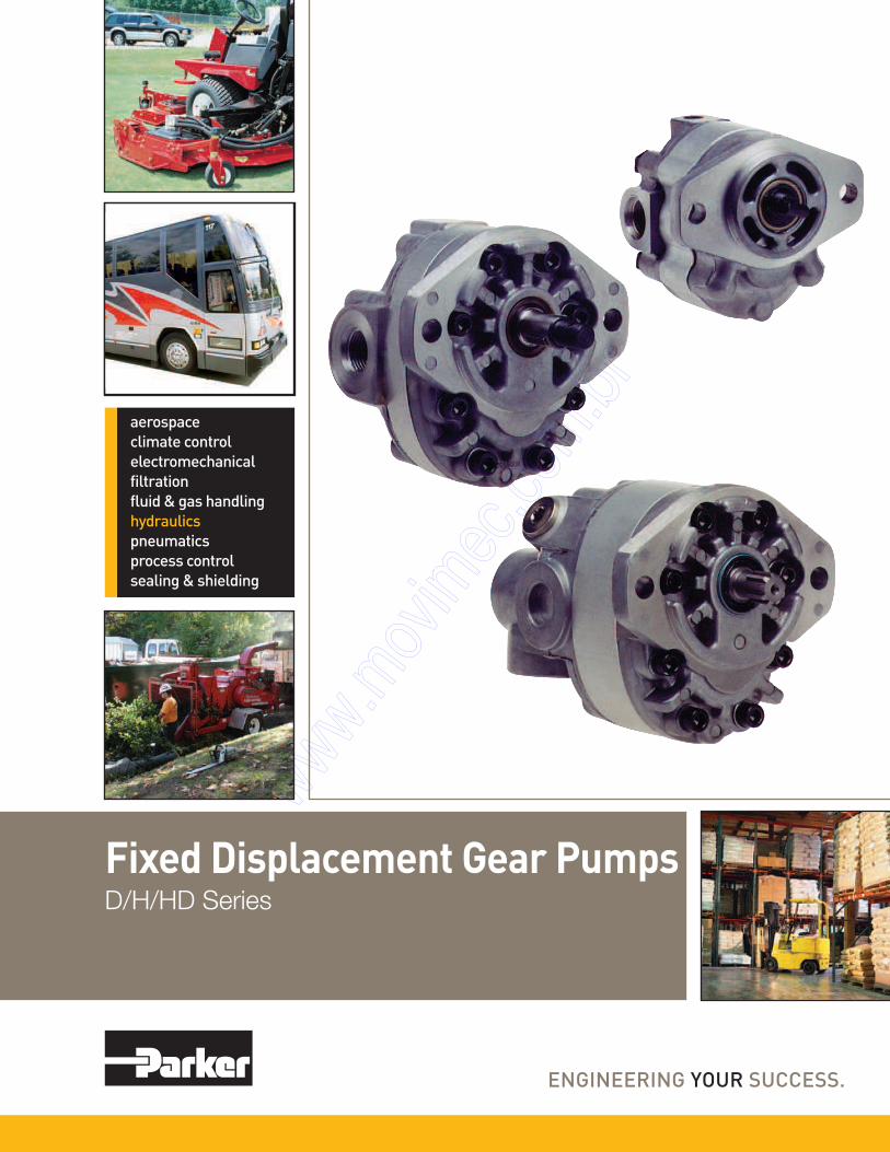
Fixed Displacement Gear PumpsD/H/HD Series

Parker Hannifin Corporation
Gear Pump Division
Kings Mountain, North Carolina USA
2
Description Page No.
Introduction ............................................................... 3
General Description .................................................. 4
“D” Series
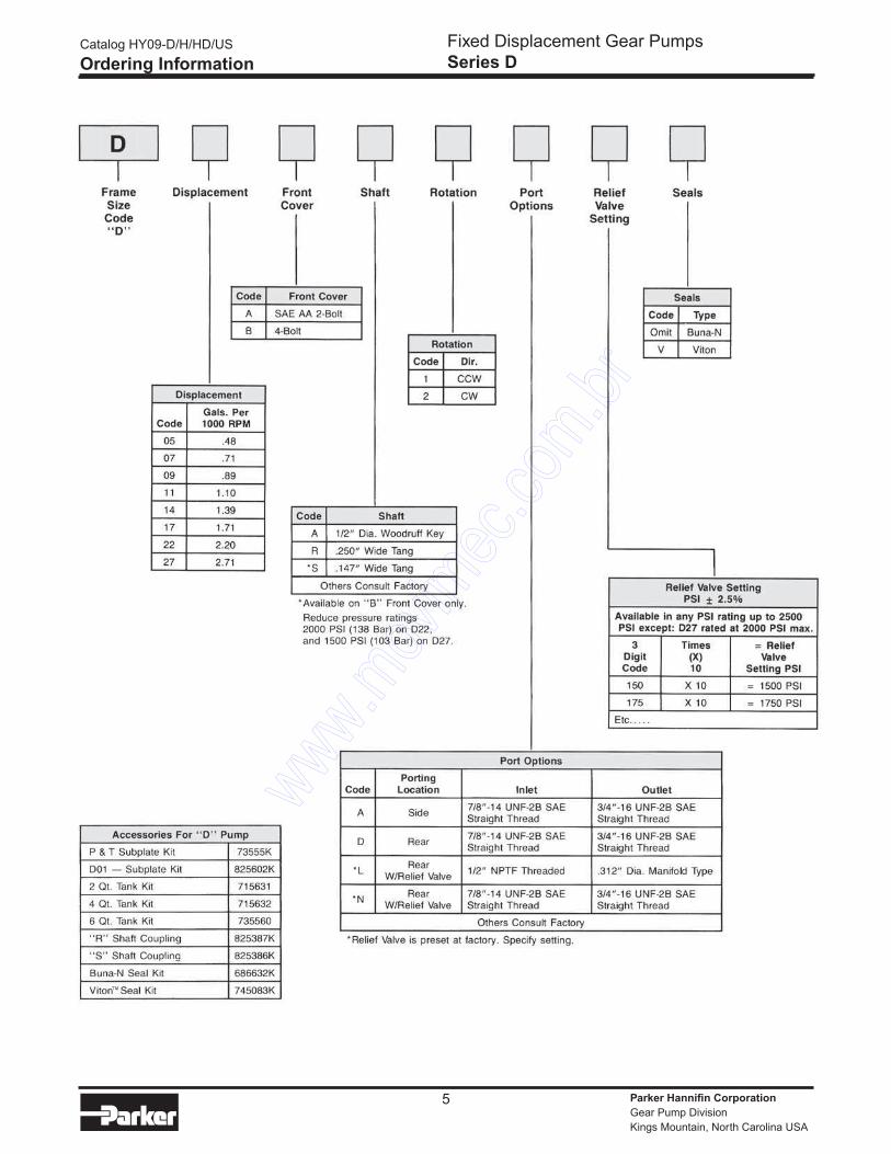
Ordering Information. ............................................ 5
Technical Information ......................................... 6-9
Dimensions ..................................................... 10-13
Dimensions - Accessories ................................... 14
“H” Series
Ordering Information. ..................................... 15-16
Technical Information ..................................... 17-20
Dimensions ..................................................... 21-22
Dimensions - Shaft Configuration ........................ 23
FAILURE OR IMPROPER SELECTION OR IMPROPER USE OF THE PRODUCTS AND/OR SYSTEMS DESCRIBED HEREIN OR RELATED ITEMS CAN CAUSE DEATH, PERSONAL
INJURY AND PROPERTY DAMAGE.
This document and other information from Parker Hannifin Corporation, its subsidiaries and authorized distributors provide product and/or system options for further investigation by users
having technical expertise. It is important that you analyze all aspects of your application and review the information concerning the product or system in the current product catalog. Due
to the variety of operating conditions and applications for these products or systems, the user, through its own analysis and testing, is solely responsible for making the final selection of
the products and systems and assuring that all performance, safety and warning requirements of the application are met.
The products described herein, including without limitation, product features, specifications, designs, availability and pricing, are subject to change by Parker Hannifin Corporation and its
subsidiaries at any time without notice.
WARNING
Copyright 2002, Parker Hannifin Corporation, All Rights Reserved
The items described in this document are hereby offered for sale by Parker Hannifin Corporation, its subsidiaries or its authorized distributors. This offer and its acceptance are governed
by the provisions stated in the “Offer of Sale”.
Offer of Sale
Catalog HY09-D/H/HD/US
Table of Contents
Fixed Displacement Gear Pumps
Series D/H/HD
“HD” Series
Ordering Information. .......................................... 24
Technical Information ..................................... 25-27
Fluid Recommendations .......................................... 28
Instructions for Reversing
Gear Pump Rotation ............................................... 29
Offer of Sale ........................................................... 30
Parker Hannifin Corporation
Gear Pump Division
Kings Mountain, North Carolina USA
3
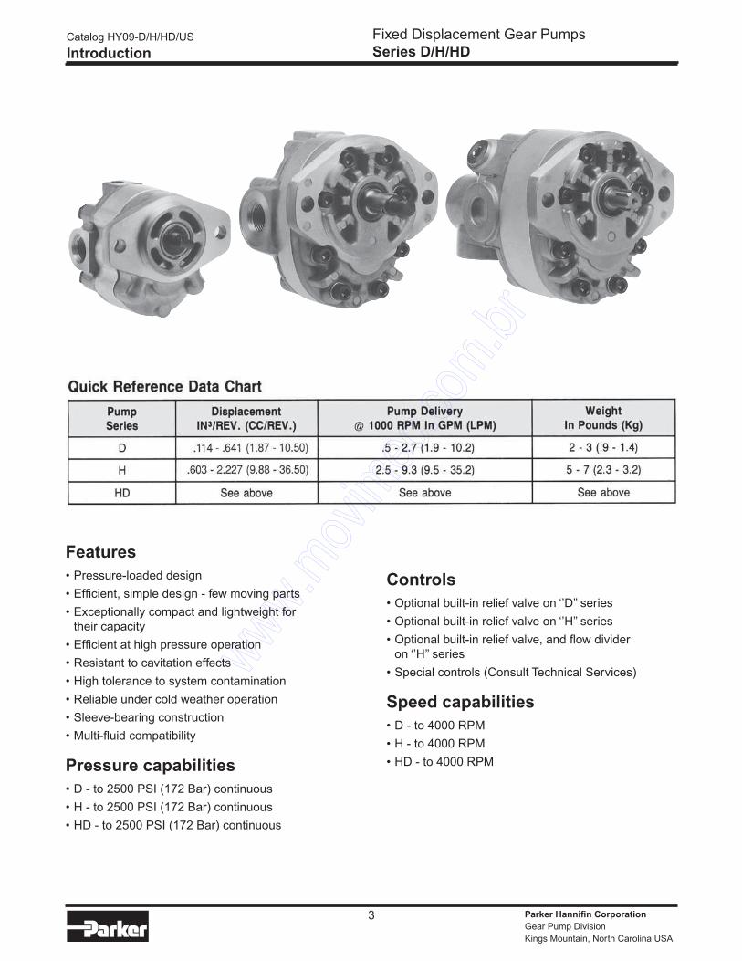
Features
• Pressure-loaded design
• Efficient, simple design - few moving parts
• Exceptionally compact and lightweight for
their capacity
• Efficient at high pressure operation
• Resistant to cavitation effects
• High tolerance to system contamination
• Reliable under cold weather operation
• Sleeve-bearing construction
• Multi-fluid compatibility
Pressure capabilities
• D - to 2500 PSI (172 Bar) continuous
• H - to 2500 PSI (172 Bar) continuous
• HD - to 2500 PSI (172 Bar) continuous
Controls
• Optional built-in relief valve on ‘’D’’ series
• Optional built-in relief valve on ‘’H’’ series
• Optional built-in relief valve, and flow divider
on ‘’H’’ series
• Special controls (Consult Technical Services)
Speed capabilities
• D - to 4000 RPM
• H - to 4000 RPM
• HD - to 4000 RPM
Catalog HY09-D/H/HD/US
Introduction
Fixed Displacement Gear Pumps
Series D/H/HD

Parker Hannifin Corporation
Gear Pump Division
Kings Mountain, North Carolina USA
4
A Parker pressure-loaded gear pump consists of two,
intermeshing, hardened-steel, precision-ground gear
assemblies. These precision gears are enclosed by
a high-strength, die-cast aluminum front cover, back
cover and a high-yield, strength-extruded aluminum
center section.
Gear assemblies consist of one drive gear, shrink-fitted
on a precision-ground and polished drive
shaft. This shaft extends outside the pump to permit
coupling to an external prime mover. The second gear,
being the driven gear, is also shrink-fitted on a preci-
sion-ground and polished driven shaft. Retaining rings,
which are installed in grooves provided on the shaft,
ensure that the gears will not move axially, and a key
keeps the drive gear from moving radially.
A lip-type, shaft seal is provided at the drive shaft to
prevent external leakage of pump fluid. The sealing
lip in contact with the fluid is spring-loaded. Vent pas-
sages within the housings and driven shaft
communicate pump inlet pressure to the rotary seal
area, thus imposing the lowest possible pressure at
the rotary seal for extended seal life.
The phenolic heat shield, backup gasket, and molded
rubber seal form chambers behind the steel-backed
bronze wearplate. These chambers are connected
either to inlet or discharge pressure. Discharge
pressure, acting within the chambers, axially loads
and deflects the wear plate toward the gear faces to
take up gear side clearances. This pressure-loading
on the wear plate increases pump efficiency by
reducing internal leakage to a minimum, providing
longer pump life.
Pump rotation is dependent upon the proper
orientation of the heat shield, backup gasket, and rub-
ber seal in the front cover housing, the center section
and rear cover, respectively.
Pumping action is achieved by connecting the pump
drive shaft to a prime mover, and rotating the gears
away from the inlet port. Rotation causes the gear
mesh to increase on the inlet side and decrease on
the outlet (pressure) side.
Catalog HY09-D/H/HD/US
General Description
Fixed Displacement Gear Pumps
Series D/H/HD
Parker Hannifin Corporation
Gear Pump Division
Kings Mountain, North Carolina USA
5
Catalog HY09-D/H/HD/US
Ordering Information
Fixed Displacement Gear Pumps
Series D
Parker Hannifin Corporation
Gear Pump Division
Kings Mountain, North Carolina USA
6
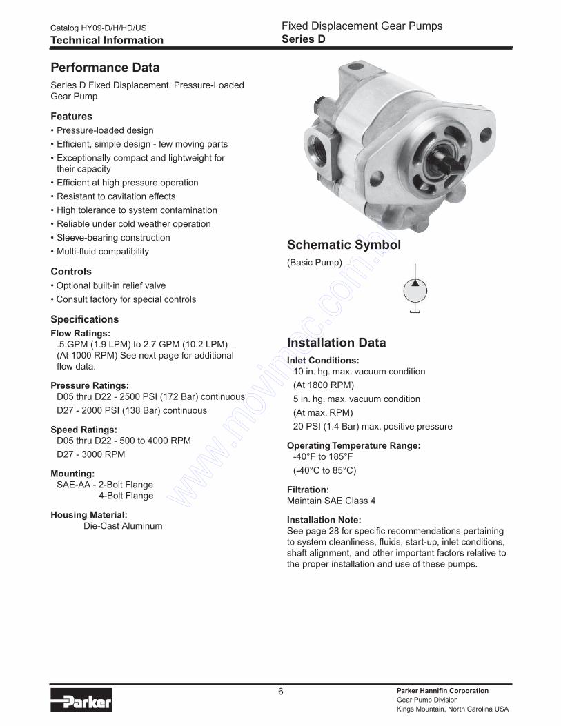
Schematic Symbol
(Basic Pump)
Installation Data
Inlet Conditions:
10 in. hg. max. vacuum condition
(At 1800 RPM)
5 in. hg. max. vacuum condition
(At max. RPM)
20 PSI (1.4 Bar) max. positive pressure
Operating Temperature Range:
-40°F to 185°F
(-40°C to 85°C)
Filtration:
Maintain SAE Class 4
Installation Note:
See page 28 for specific recommendations pertaining
to system cleanliness, fluids, start-up, inlet conditions,
shaft alignment, and other important factors relative to
the proper installation and use of these pumps.
Performance Data
Series D Fixed Displacement, Pressure-Loaded
Gear Pump
Features
• Pressure-loaded design
• Efficient, simple design - few moving parts
• Exceptionally compact and lightweight for
their capacity
• Efficient at high pressure operation
• Resistant to cavitation effects
• High tolerance to system contamination
• Reliable under cold weather operation
• Sleeve-bearing construction
• Multi-fluid compatibility
Controls
• Optional built-in relief valve
• Consult factory for special controls
Specifications
Flow Ratings:
.5 GPM (1.9 LPM) to 2.7 GPM (10.2 LPM)
(At 1000 RPM) See next page for additional
flow data.
Pressure Ratings:
D05 thru D22 - 2500 PSI (172 Bar) continuous
D27 - 2000 PSI (138 Bar) continuous
Speed Ratings:
D05 thru D22 - 500 to 4000 RPM
D27 - 3000 RPM
Mounting:
SAE-AA - 2-Bolt Flange
4-Bolt Flange
Housing Material:
Die-Cast Aluminum
Catalog HY09-D/H/HD/US
Technical Information
Fixed Displacement Gear Pumps
Series D
Parker Hannifin Corporation
Gear Pump Division
Kings Mountain, North Carolina USA
7
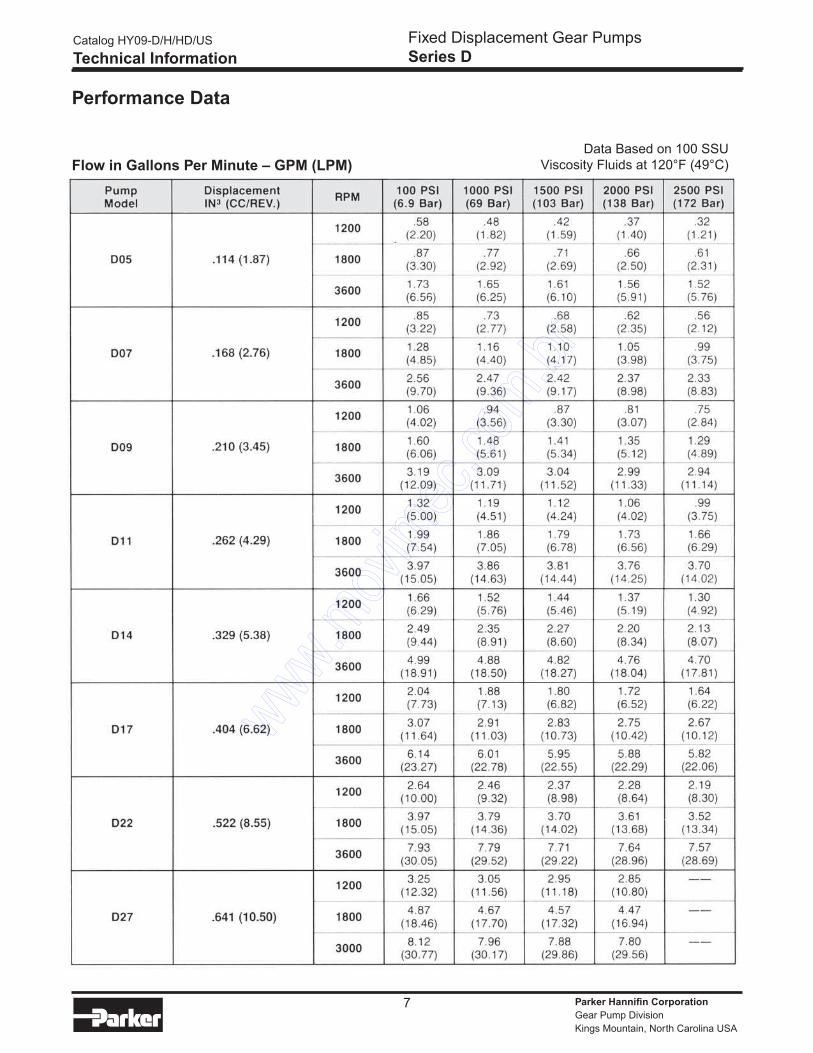
Performance Data
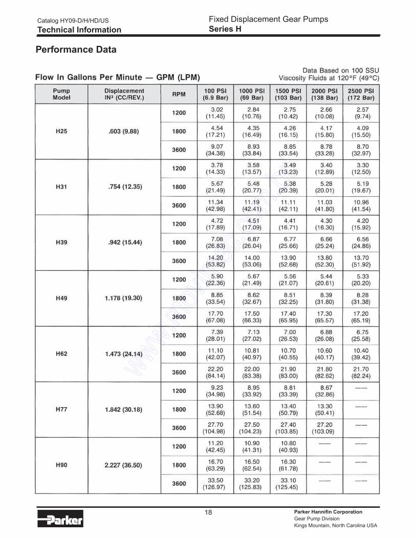
Flow in Gallons Per Minute – GPM (LPM)Data Based on 100 SSU
Viscosity Fluids at 120°F (49°C)
Catalog HY09-D/H/HD/US
Technical Information
Fixed Displacement Gear Pumps
Series D
Parker Hannifin Corporation
Gear Pump Division
Kings Mountain, North Carolina USA
8
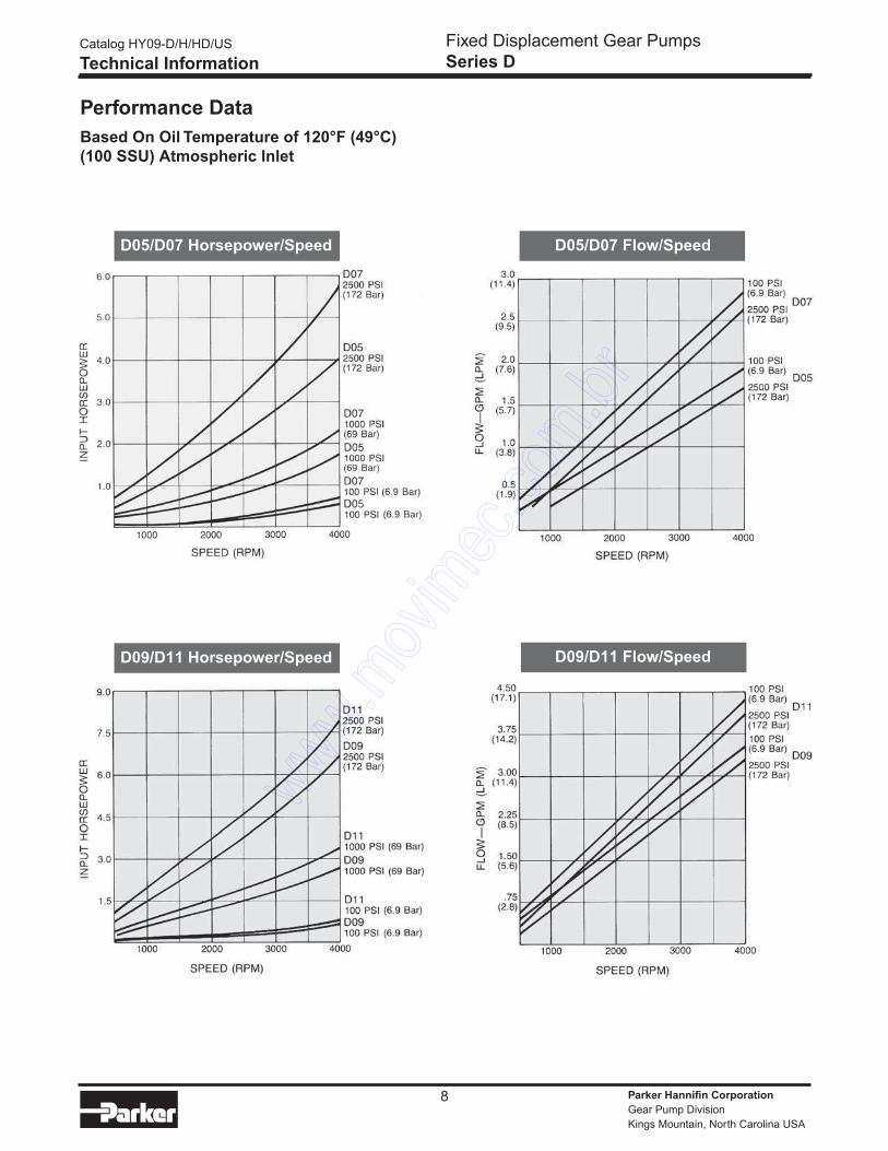
Performance Data
Based On Oil Temperature of 120°F (49°C)
(100 SSU) Atmospheric Inlet
D09
Catalog HY09-D/H/HD/US
Technical Information
Fixed Displacement Gear Pumps
Series D
D09/D11 Horsepower/Speed D09/D11 Flow/Speed
D05/D07 Flow/SpeedD05/D07 Horsepower/Speed
Parker Hannifin Corporation
Gear Pump Division
Kings Mountain, North Carolina USA
9
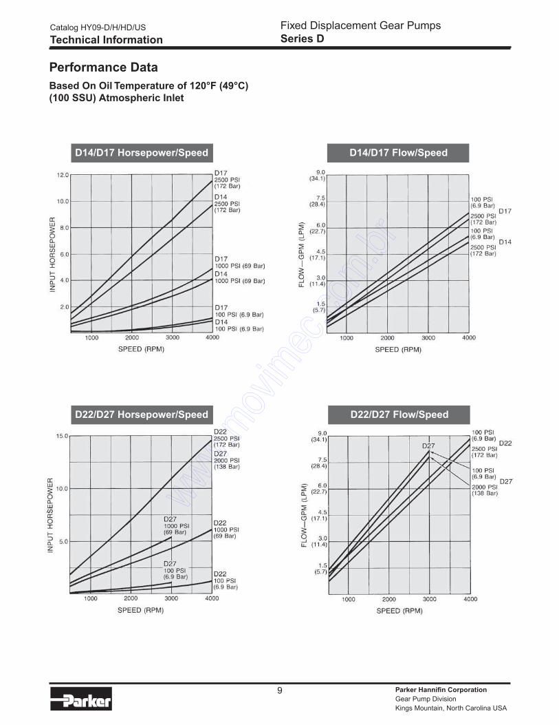
Performance Data
Based On Oil Temperature of 120°F (49°C)
(100 SSU) Atmospheric Inlet
Catalog HY09-D/H/HD/US
Technical Information
Fixed Displacement Gear Pumps
Series D
D14/D17 Flow/SpeedD14/D17 Horsepower/Speed
D22/D27 Flow/SpeedD22/D27 Horsepower/Speed
Parker Hannifin Corporation
Gear Pump Division
Kings Mountain, North Carolina USA
10
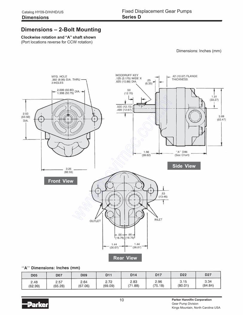
Dimensions – 2-Bolt Mounting
Clockwise rotation and “A” shaft shown
(Port locations reverse for CCW rotation)
Front View
Rear View
Side View
Dimensions: Inches (mm)
Catalog HY09-D/H/HD/US
Dimensions
Fixed Displacement Gear Pumps
Series D
Parker Hannifin Corporation
Gear Pump Division
Kings Mountain, North Carolina USA
11
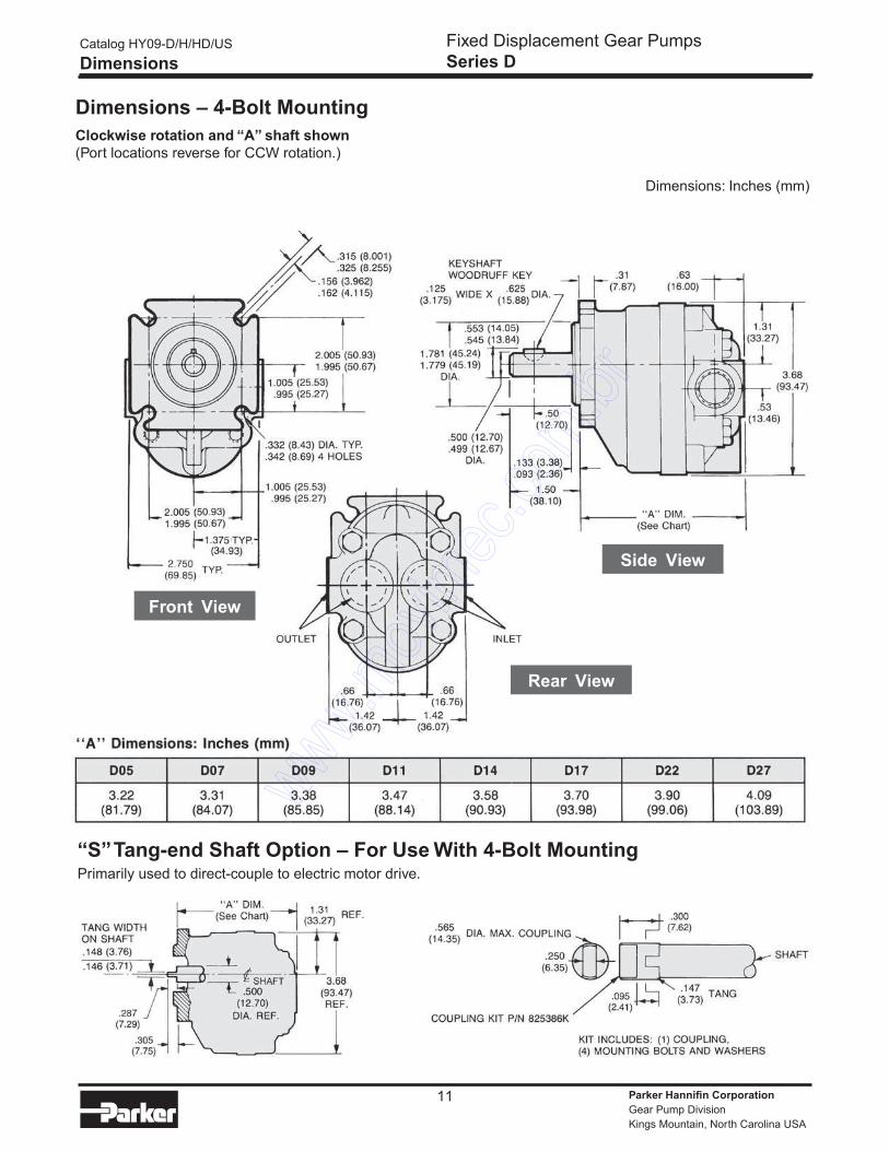
Dimensions – 4-Bolt Mounting
Clockwise rotation and “A” shaft shown
(Port locations reverse for CCW rotation.)
Front View
Side View
Rear View
“S” Tang-end Shaft Option – For Use With 4-Bolt MountingPrimarily used to direct-couple to electric motor drive.
Dimensions: Inches (mm)
Catalog HY09-D/H/HD/US
Dimensions
Fixed Displacement Gear Pumps
Series D
Parker Hannifin Corporation
Gear Pump Division
Kings Mountain, North Carolina USA
12
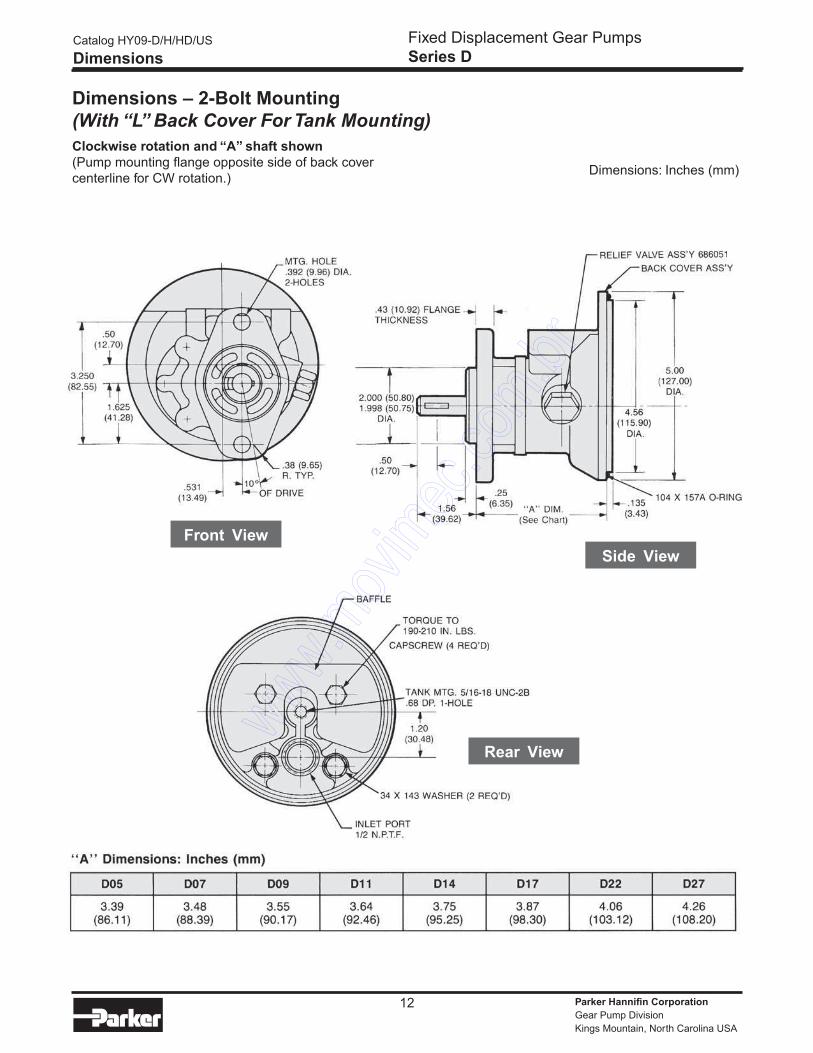
Dimensions – 2-Bolt Mounting
(With “L” Back Cover For Tank Mounting)
Clockwise rotation and “A” shaft shown
(Pump mounting flange opposite side of back cover
centerline for CW rotation.)
Side View
Front View
Rear View
Dimensions: Inches (mm)
Catalog HY09-D/H/HD/US
Dimensions
Fixed Displacement Gear Pumps
Series D
Parker Hannifin Corporation
Gear Pump Division
Kings Mountain, North Carolina USA
13
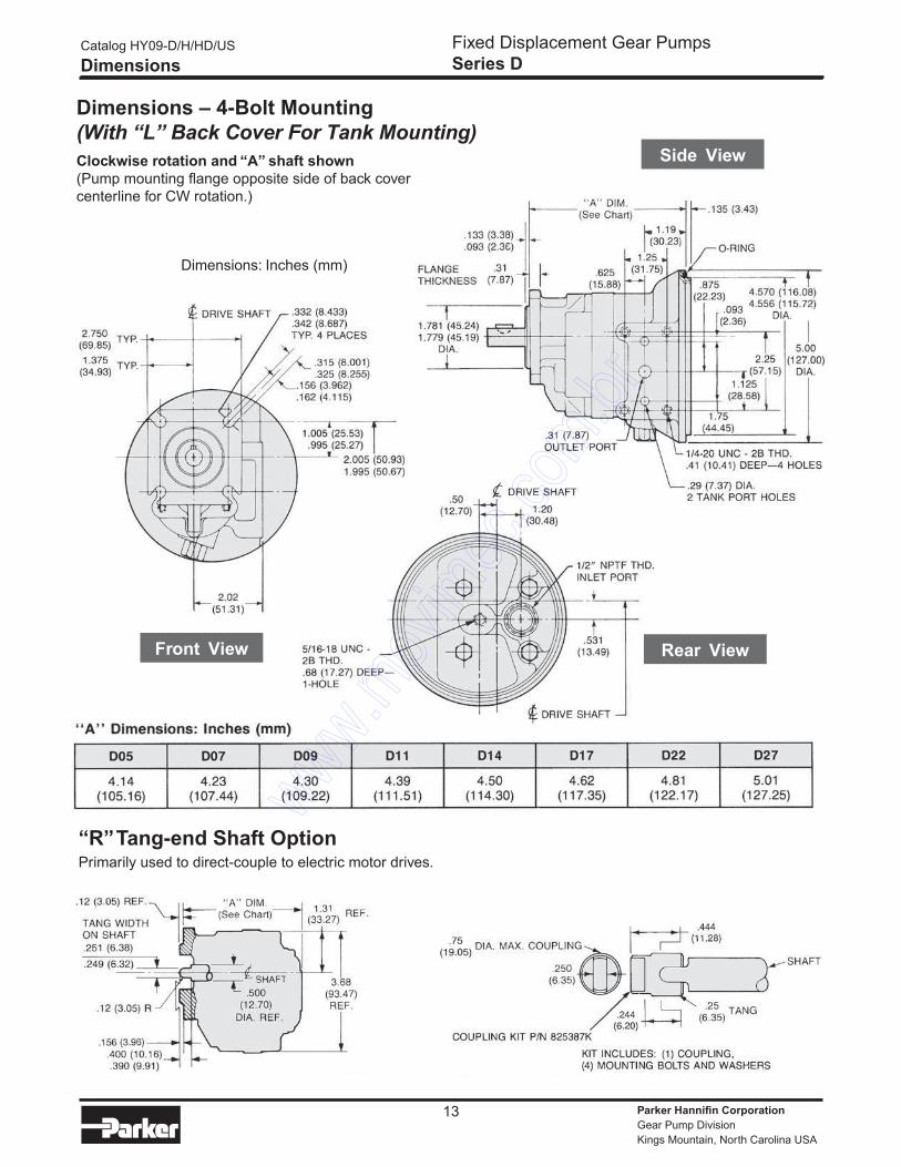
Dimensions – 4-Bolt Mounting
(With “L” Back Cover For Tank Mounting)
Clockwise rotation and “A” shaft shown
(Pump mounting flange opposite side of back cover
centerline for CW rotation.)
“R” Tang-end Shaft OptionPrimarily used to direct-couple to electric motor drives.
Front View
Side View
Dimensions: Inches (mm)
Catalog HY09-D/H/HD/US
Dimensions
Fixed Displacement Gear Pumps
Series D
Rear View
Parker Hannifin Corporation
Gear Pump Division
Kings Mountain, North Carolina USA
14
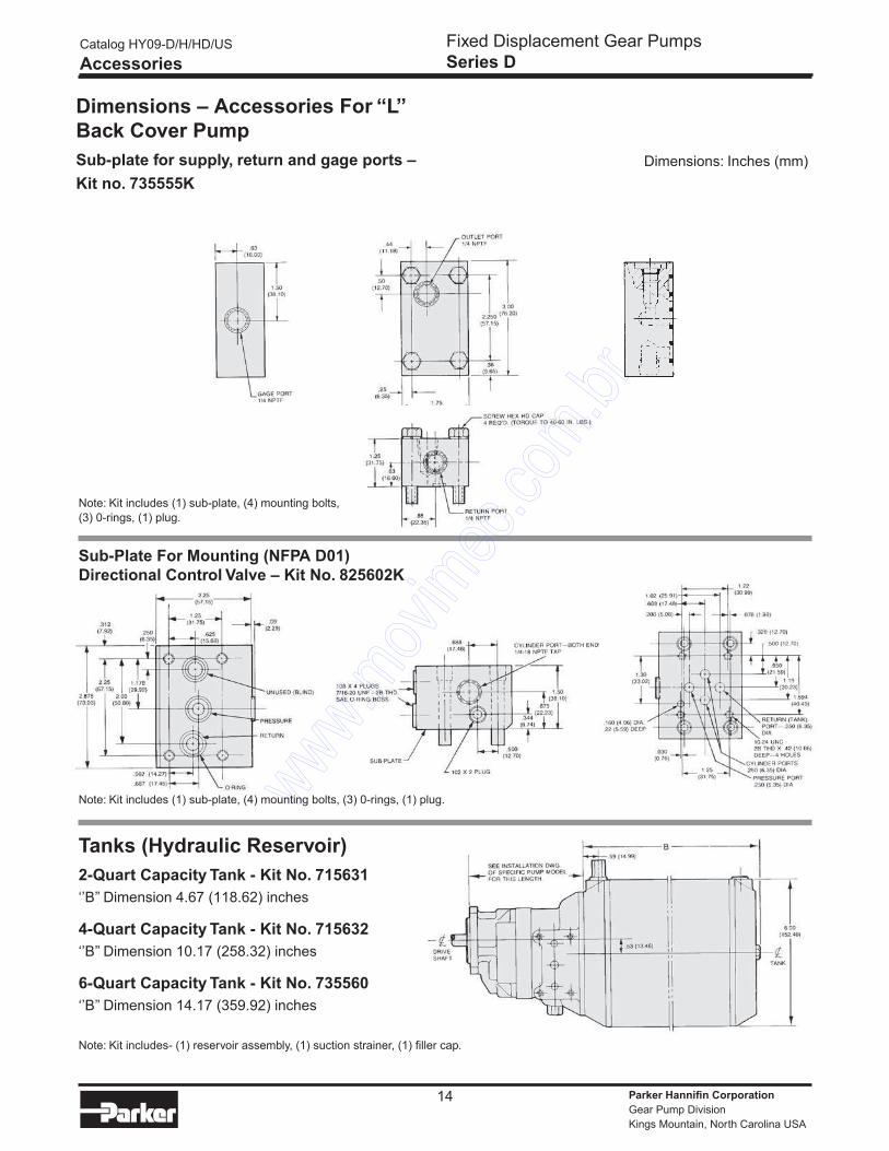
Dimensions – Accessories For “L”
Back Cover Pump
Sub-plate for supply, return and gage ports –
Kit no. 735555K
Note: Kit includes (1) sub-plate, (4) mounting bolts,
(3) 0-rings, (1) plug.
Sub-Plate For Mounting (NFPA D01)
Directional Control Valve – Kit No. 825602K
Tanks (Hydraulic Reservoir)
2-Quart Capacity Tank - Kit No. 715631
‘’B’’ Dimension 4.67 (118.62) inches
4-Quart Capacity Tank - Kit No. 715632
‘’B’’ Dimension 10.17 (258.32) inches
6-Quart Capacity Tank - Kit No. 735560
‘’B’’ Dimension 14.17 (359.92) inches
Note: Kit includes- (1) reservoir assembly, (1) suction strainer, (1) filler cap.
Note: Kit includes (1) sub-plate, (4) mounting bolts, (3) 0-rings, (1) plug.
Dimensions: Inches (mm)
Catalog HY09-D/H/HD/US
Accessories
Fixed Displacement Gear Pumps
Series D
Parker Hannifin Corporation
Gear Pump Division
Kings Mountain, North Carolina USA
15
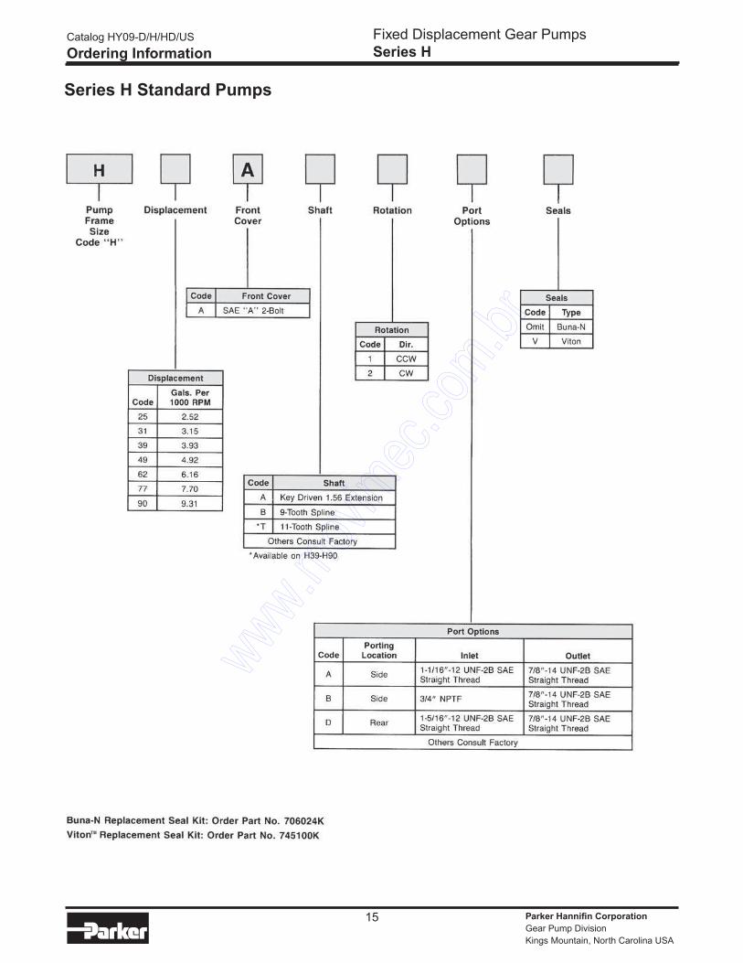
Series H Standard Pumps
Catalog HY09-D/H/HD/US
Ordering Information
Fixed Displacement Gear Pumps
Series H
Parker Hannifin Corporation
Gear Pump Division
Kings Mountain, North Carolina USA
16
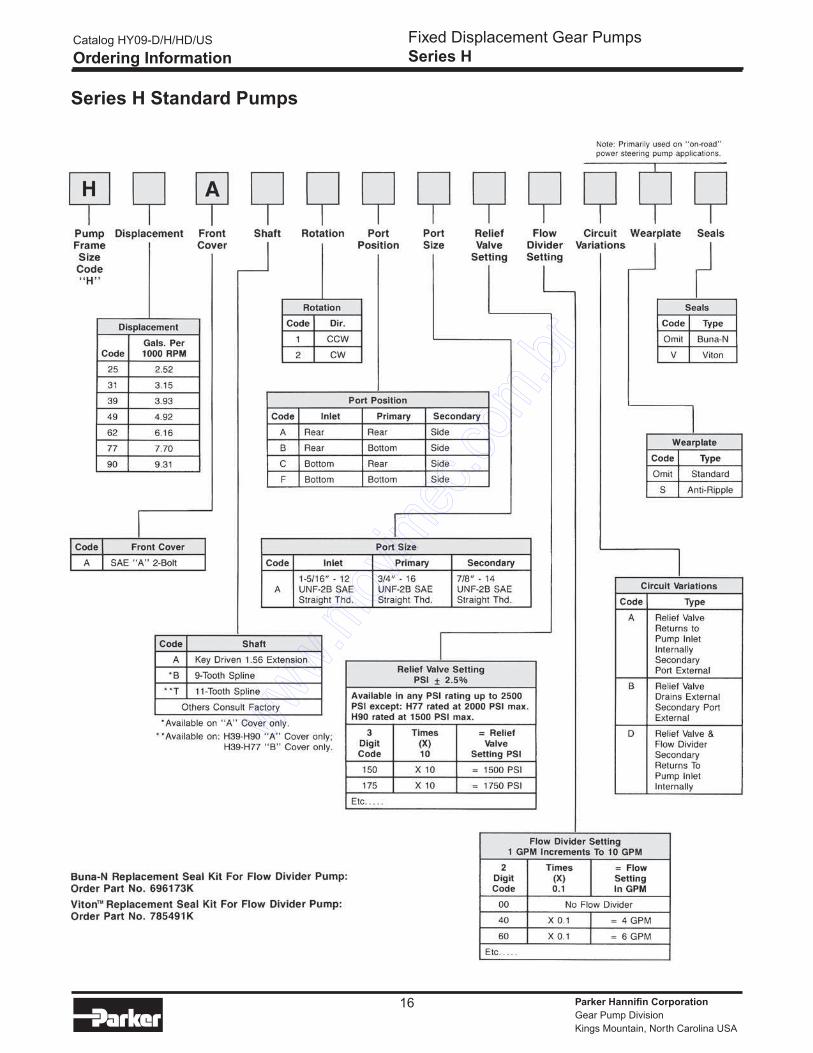
Series H Standard Pumps
Catalog HY09-D/H/HD/US
Ordering Information
Fixed Displacement Gear Pumps
Series H
Parker Hannifin Corporation
Gear Pump Division
Kings Mountain, North Carolina USA
17
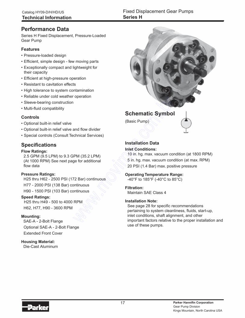
Performance DataSeries H Fixed Displacement, Pressure-Loaded
Gear Pump
Features
• Pressure-loaded design
• Efficient, simple design - few moving parts
• Exceptionally compact and lightweight for
their capacity
• Efficient at high-pressure operation
• Resistant to cavitation effects
• High tolerance to system contamination
• Reliable under cold weather operation
• Sleeve-bearing construction
• Multi-fluid compatibility
Controls
• Optional built-in relief valve
• Optional built-in relief valve and flow divider
• Special controls (Consult Technical Services)
SpecificationsFlow Ratings:
2.5 GPM (9.5 LPM) to 9.3 GPM (35.2 LPM)
(At 1000 RPM) See next page for additional
flow data
Pressure Ratings:
H25 thru H62 - 2500 PSI (172 Bar) continuous
H77 - 2000 PSI (138 Bar) continuous
H90 - 1500 PSI (103 Bar) continuous
Speed Ratings:
H25 thru H49 - 500 to 4000 RPM
H62, H77, H90 - 3600 RPM
Mounting:
SAE-A - 2-Bolt Flange
Optional SAE-A - 2-Bolt Flange
Extended Front Cover
Housing Material:
Die-Cast Aluminum
Schematic Symbol
(Basic Pump)
Installation Data
Inlet Conditions:
10 in. hg. max. vacuum condition (at 1800 RPM)
5 in. hg. max. vacuum condition (at max. RPM)
20 PSI (1.4 Bar) max. positive pressure
Operating Temperature Range:
-40°F to 185°F (-40°C to 85°C)
Filtration:
Maintain SAE Class 4
Installation Note:
See page 28 for specific recommendations
pertaining to system cleanliness, fluids, start-up,
inlet conditions, shaft alignment, and other
important factors relative to the proper installation and
use of these pumps.
Catalog HY09-D/H/HD/US
Technical Information
Fixed Displacement Gear Pumps
Series H
Parker Hannifin Corporation
Gear Pump Division
Kings Mountain, North Carolina USA
18
Performance Data
Catalog HY09-D/H/HD/US
Technical Information
Fixed Displacement Gear Pumps
Series H
Parker Hannifin Corporation
Gear Pump Division
Kings Mountain, North Carolina USA
19
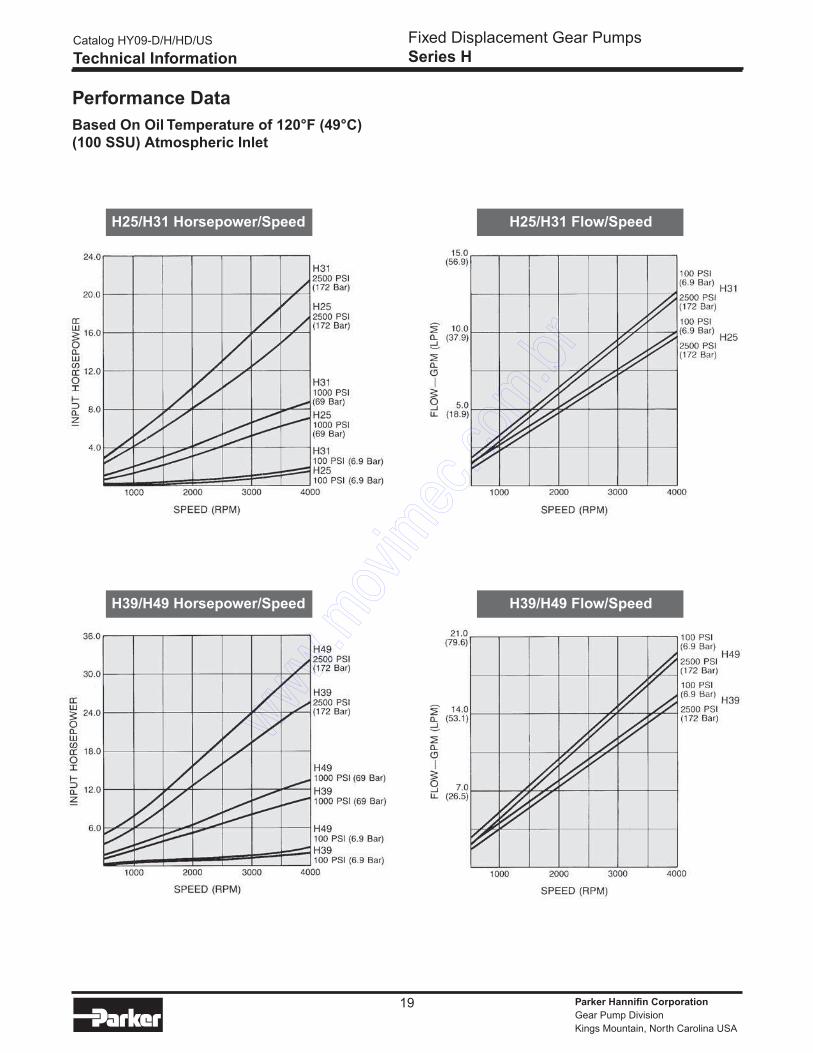
Performance Data
Based On Oil Temperature of 120°F (49°C)
(100 SSU) Atmospheric Inlet
Catalog HY09-D/H/HD/US
Technical Information
Fixed Displacement Gear Pumps
Series H
H25/H31 Flow/SpeedH25/H31 Horsepower/Speed
H39/H49 Flow/SpeedH39/H49 Horsepower/Speed
Parker Hannifin Corporation
Gear Pump Division
Kings Mountain, North Carolina USA
20
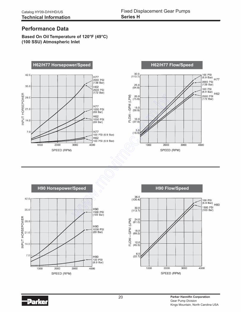
Performance Data
Based On Oil Temperature of 120°F (49°C)
(100 SSU) Atmospheric Inlet
Catalog HY09-D/H/HD/US
Technical Information
Fixed Displacement Gear Pumps
Series H
H62/H77 Flow/SpeedH62/H77 Horsepower/Speed
H90 Flow/SpeedH90 Horsepower/Speed

Parker Hannifin Corporation
Gear Pump Division
Kings Mountain, North Carolina USA
21
Dimensions – 2-Bolt Mounting
Clockwise rotation and “A” shaft shown
(Port locations reverse for CCW rotation.)
Front View
Rear View
Side View
Cover Option
“A” COVER
Dimensions: Inches (mm)
Catalog HY09-D/H/HD/US
Dimensions
Fixed Displacement Gear Pumps
Series H
Parker Hannifin Corporation
Gear Pump Division
Kings Mountain, North Carolina USA
22
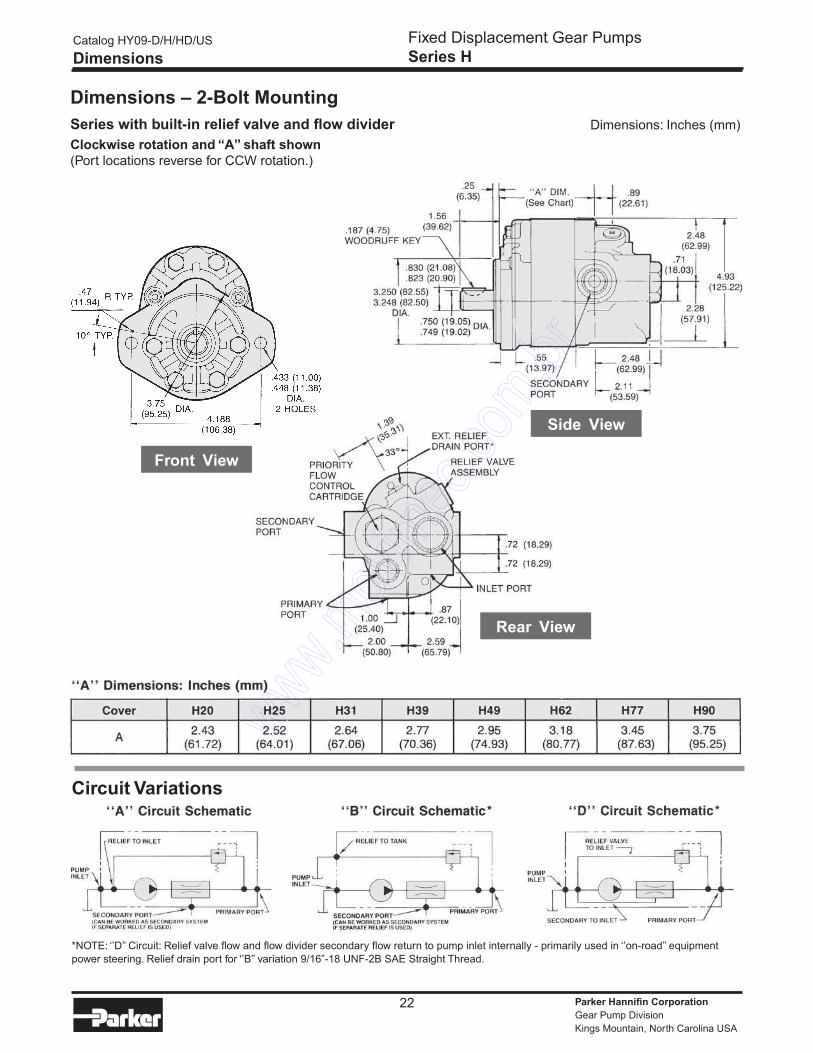
Dimensions – 2-Bolt Mounting
Series with built-in relief valve and flow divider
Clockwise rotation and “A” shaft shown
(Port locations reverse for CCW rotation.)
Front View
Rear View
Side View
Circuit Variations
*NOTE: ‘’D’’ Circuit: Relief valve flow and flow divider secondary flow return to pump inlet internally - primarily used in ‘’on-road’’ equipment
power steering. Relief drain port for ‘’B’’ variation 9/16”-18 UNF-2B SAE Straight Thread.
Dimensions: Inches (mm)
Catalog HY09-D/H/HD/US
Dimensions
Fixed Displacement Gear Pumps
Series H
Parker Hannifin Corporation
Gear Pump Division
Kings Mountain, North Carolina USA
23
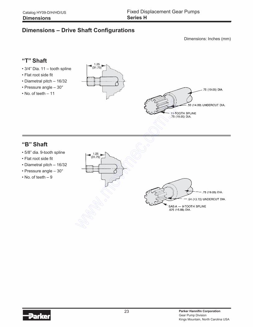
Dimensions – Drive Shaft Configurations
“T” Shaft
• 3/4” Dia. 11 – tooth spline
• Flat root side fit
• Diametral pitch – 16/32
• Pressure angle – 30°
• No. of teeth – 11
“B” Shaft
• 5/8” dia. 9-tooth spline
• Flat root side fit
• Diametral pitch – 16/32
• Pressure angle – 30°
• No. of teeth – 9
Dimensions: Inches (mm)
Catalog HY09-D/H/HD/US
Dimensions
Fixed Displacement Gear Pumps
Series H
Parker Hannifin Corporation
Gear Pump Division
Kings Mountain, North Carolina USA
24
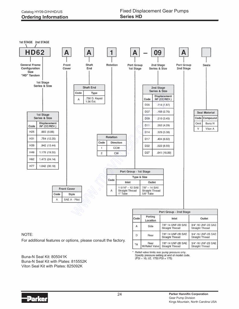
NOTE:
For additional features or options, please consult the factory.
Buna-N Seal Kit: 805041K
Buna-N Seal Kit with Plates: 815552K
Viton Seal Kit with Plates: 825092K
Catalog HY09-D/H/HD/US
Ordering Information
Fixed Displacement Gear Pumps
Series HD
Parker Hannifin Corporation
Gear Pump Division
Kings Mountain, North Carolina USA
25
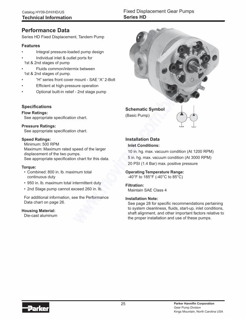
Performance DataSeries HD Fixed Displacement, Tandem Pump
Features
• Integral pressure-loaded pump design
• Individual inlet & outlet ports for
1st & 2nd stages of pump
• Fluids common/intermix between
1st & 2nd stages of pump.
• “H” series front cover mount - SAE “A” 2-Bolt
• Efficient at high-pressure operation
• Optional built-in relief - 2nd stage pump
Specifications
Flow Ratings:
See appropriate specification chart.
Pressure Ratings:
See appropriate specification chart.
Speed Ratings:
Minimum: 500 RPM
Maximum: Maximum rated speed of the larger
displacement of the two pumps.
See appropriate specification chart for this data.
Torque:
• Combined: 800 in. lb. maximum total
continuous duty
• 950 in. lb. maximum total intermittent duty
• 2nd Stage pump cannot exceed 260 in. lb.
For additional information, see the Performance
Data chart on page 26.
Housing Material:
Die-cast aluminum
Installation Data
Inlet Conditions:
10 in. hg. max. vacuum condition (At 1200 RPM)
5 in. hg. max. vacuum condition (At 3000 RPM)
20 PSI (1.4 Bar) max. positive pressure
Operating Temperature Range:
-40°F to 185°F (-40°C to 85°C)
Filtration:
Maintain SAE Class 4
Installation Note:
See page 28 for specific recommendations pertaining
to system cleanliness, fluids, start-up, inlet conditions,
shaft alignment, and other important factors relative to
the proper installation and use of these pumps.
Schematic Symbol
(Basic Pump)
Catalog HY09-D/H/HD/US
Technical Information
Fixed Displacement Gear Pumps
Series HD
Parker Hannifin Corporation
Gear Pump Division
Kings Mountain, North Carolina USA
26
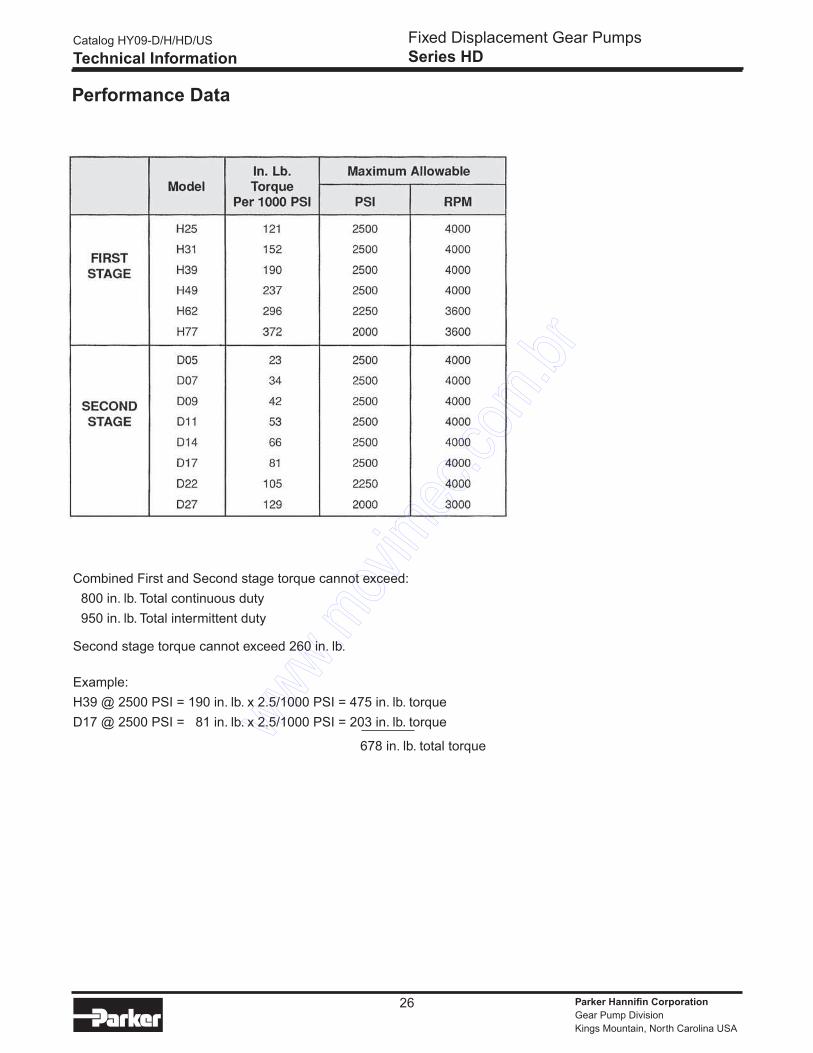
Performance Data
Combined First and Second stage torque cannot exceed:
800 in. lb. Total continuous duty
950 in. lb. Total intermittent duty
Second stage torque cannot exceed 260 in. lb.
Example:
H39 @ 2500 PSI = 190 in. lb. x 2.5/1000 PSI = 475 in. lb. torque
D17 @ 2500 PSI = 81 in. lb. x 2.5/1000 PSI = 203 in. lb. torque
678 in. lb. total torque
Catalog HY09-D/H/HD/US
Technical Information
Fixed Displacement Gear Pumps
Series HD
Parker Hannifin Corporation
Gear Pump Division
Kings Mountain, North Carolina USA
27
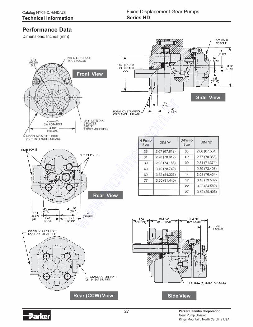
Performance DataDimensions: Inches (mm)
Front View
Side View
Side ViewRear (CCW) View
Rear View
Catalog HY09-D/H/HD/US
Technical Information
Fixed Displacement Gear Pumps
Series HD
Parker Hannifin Corporation
Gear Pump Division
Kings Mountain, North Carolina USA
28
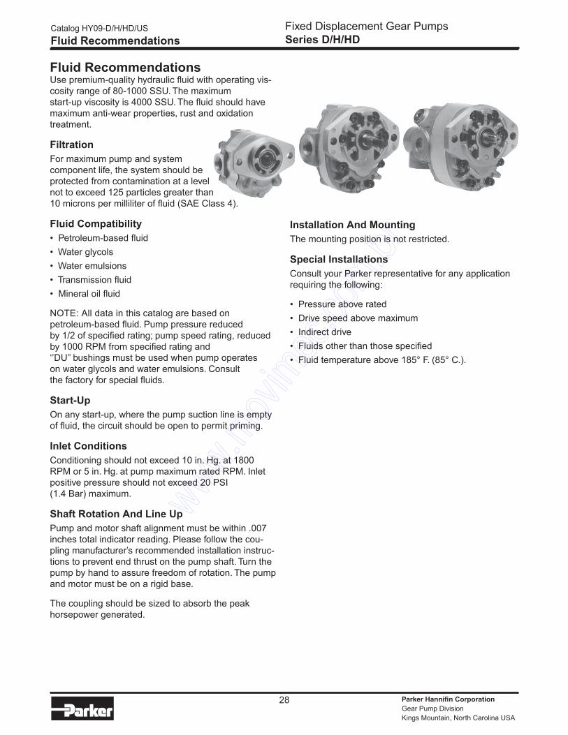
Fluid RecommendationsUse premium-quality hydraulic fluid with operating vis-
cosity range of 80-1000 SSU. The maximum
start-up viscosity is 4000 SSU. The fluid should have
maximum anti-wear properties, rust and oxidation
treatment.
Filtration
For maximum pump and system
component life, the system should be
protected from contamination at a level
not to exceed 125 particles greater than
10 microns per milliliter of fluid (SAE Class 4).
Fluid Compatibility
• Petroleum-based fluid
• Water glycols
• Water emulsions
• Transmission fluid
• Mineral oil fluid
NOTE: All data in this catalog are based on
petroleum-based fluid. Pump pressure reduced
by 1/2 of specified rating; pump speed rating, reduced
by 1000 RPM from specified rating and
‘’DU’’ bushings must be used when pump operates
on water glycols and water emulsions. Consult
the factory for special fluids.
Start-Up
On any start-up, where the pump suction line is empty
of fluid, the circuit should be open to permit priming.
Inlet Conditions
Conditioning should not exceed 10 in. Hg. at 1800
RPM or 5 in. Hg. at pump maximum rated RPM. Inlet
positive pressure should not exceed 20 PSI
(1.4 Bar) maximum.
Shaft Rotation And Line Up
Pump and motor shaft alignment must be within .007
inches total indicator reading. Please follow the cou-
pling manufacturer’s recommended installation instruc-
tions to prevent end thrust on the pump shaft. Turn the
pump by hand to assure freedom of rotation. The pump
and motor must be on a rigid base.
The coupling should be sized to absorb the peak
horsepower generated.
Installation And Mounting
The mounting position is not restricted.
Special Installations
Consult your Parker representative for any application
requiring the following:
• Pressure above rated
• Drive speed above maximum
• Indirect drive
• Fluids other than those specified
• Fluid temperature above 185° F. (85° C.).
Catalog HY09-D/H/HD/US
Fluid Recommendations
Fixed Displacement Gear Pumps
Series D/H/HD
Parker Hannifin Corporation
Gear Pump Division
Kings Mountain, North Carolina USA
29
Instructions for Reversing Gear
Pump Rotation
The basic tools needed are a vise, preferably with soft
jaws, a torque wrench, a thin screwdriver, a small hone
stone, a ratchet and a paper clip. The ‘’D’’ series will
require a 1-1/2’’ socket; the ‘’H’’ series an additional
1/4’’ hex head driver. It is also recommended that you
have extra heat shields and gaskets on hand. Part
numbers are 655287 and 655288 for the ‘’HD’’ series;
656942 and 656943 for ‘’H’’ series.
To change rotation, hold the pump by the rear cover
with the drive shaft pointing up. Remove all the bolts.
The “HD’’ series will have four hex heads, and the ‘’H’’
series will have six hex and two alien heads. For future
reference, it would be helpful to scribe a line down the
outlet side of the pump. If you choose not to mark it,
the outlet port is usually the smallest.
If the pump has a key-type shaft, remove the key and
hone down any burrs that may be on the shaft. This
is important as the next step will be to lift off the front
cover, and any sharp edges could possibly damage the
front seal or bearing.
After the front cover is off, note the position of the little
vent hole in the bronze wear plate, which should have
come off with the front cover. The parts underneath
also have a similar vent hole.
Remove in order, the wear plate, the heat shield, the
gasket, and the V-seal. To facilitate this, make a small
hook with a paper clip and lift the part high enough to
slip a screwdriver under it and carefully pry up. Please
note that the heat shield, in particular, is very brittle
and may crack if bent.
After removing these four parts, reinstall the V-seal with
the lips down in the front cover so that the vent hole is
on the opposite side across from the reference mark.
Use the screwdriver to seat it completely. Next, install
the gasket, heat shield, and wear plate; again with the
vent hole in line with that of the V-seal. The wear plate
should be almost flush with the surface of the front
cover.
Remove the center section and note the notch cut on
the inside. This will be installed in line and next to the
vent hole in the wear plate. The dowel pins used to
locate the center section may be removed temporar-
ily to facilitate sliding the center section over the gear
assemblies. Be careful not to pinch the O-ring between
the front cover and center section. If it doesn’t want to
stay in place, it can be ‘’glued’’ using heavy grease.
If the pump is an “ H ‘’ series, install the thrust plate
into the center section, orienting the side with the bar
in line with the vent hole, ensuring that the bronze side
faces the gears.
The rear cover is installed with the outlet side in line
with the vent hole. The outlet side will be marked or
can be identified by the smaller, internal cavity. As when
installing the center section, be careful not to pinch the
O-ring seal.
The line that was originally scribed on the side should
now be located at 180° on both the rear cover and cen-
ter section from that on the front cover.
Install the bolts and tighten down by hand. Then, torque
to the proper setting, alternating from side to side. The
correct torque specifications are 190-210’’ lbs. for the ‘’
D’’ and ‘’ H ‘’ series. Reverse or remove the rotation ar-
row originally stamped on the
mounting flange.
Testing Procedure
After the pump has been reinstalled, run for 2-3
minutes before pressurizing. Try to apply pressure
gradually for an additional five minutes, but do not pres-
surize for longer than 5 seconds at a time.
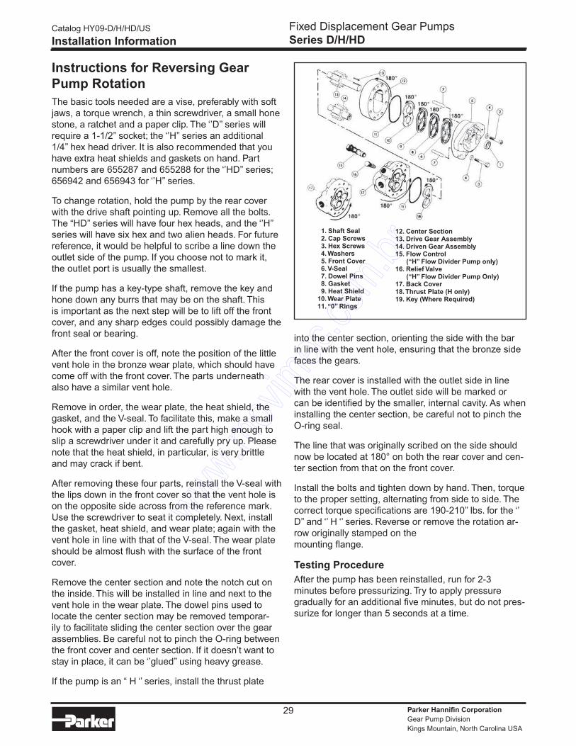
12. Center Section13. Drive Gear Assembly14. Driven Gear Assembly15. Flow Control (“H” Flow Divider Pump only)16. Relief Valve (“H” Flow Divider Pump Only)17. Back Cover18. Thrust Plate (H only)19. Key (Where Required)
1. Shaft Seal 2. Cap Screws 3. Hex Screws 4. Washers 5. Front Cover 6. V-Seal 7. Dowel Pins 8. Gasket 9. Heat Shield10. Wear Plate11. “0” Rings
Catalog HY09-D/H/HD/US
Installation Information
Fixed Displacement Gear Pumps
Series D/H/HD
Parker Hannifin Corporation
Gear Pump Division
Kings Mountain, North Carolina USA
30
The items described in this document and other documents or descriptions provided by Parker Hannifin Corporation, its subsidiaries and its autho-rized distributors are hereby offered for sale at prices to be established by Parker Hannifin Corporation, its subsidiaries and its authorized distributors. This offer and its acceptance by any customer (“Buyer”) shall be governed by all of the following Terms and Conditions. Buyer’s order for any such items, when communicated to Parker Hannifin Corporation, its subsidiary or an authorized distributor (“Seller”) verbally or in writing, shall constitute acceptance of this offer.
1. Terms and Conditions of Sale: All descriptions, quotations, proposals, offers, acknowledgments, acceptances and sales of Seller’s products are subject to and shall be governed exclusively by the terms and conditions stated herein. Buyer’s acceptance of any offer to sell is limited to these terms and conditions. Any terms or conditions in addition to, or inconsistent with those stated herein, proposed by Buyer in any acceptance of an offer by Seller, are hereby objected to. No such additional, different or inconsistent terms and conditions shall become part of the contract between Buyer and Seller unless expressly accepted in writing by Seller. Seller’s acceptance of any offer to purchase by Buyer is expressly conditional upon Buyer’s assent to all the terms and conditions stated herein, including any terms in addition to, or inconsistent with those contained in Buyer’s offer, Acceptance of Seller’s products shall in all events constitute such assent.2. Payment: Payment shall be made by Buyer net 30 days from the date of delivery of the items purchased hereunder. Amounts not timely paid shall bear interest at the maximum rate permitted by law for each month or portion thereof that the Buyer is late in making payment. Any claims by Buyer for omissions or shortages in a shipment shall be waived unless Seller receives notice thereof within 30 days after Buyer’s receipt of the shipment.3. Delivery: Unless otherwise provided on the face hereof, delivery shall be made F.O.B. Seller’s plant. Regardless of the method of delivery, how-ever, risk of loss shall pass to Buyer upon Seller’s delivery to a carrier. Any delivery dates shown are approximate only and Seller shall have no liability for any delays in delivery.4. Warranty: Seller warrants that the items sold hereunder shall be free from defects in material or workmanship for a period of 18 months from date of shipment from Parker Hannifin Corporation. THIS WARRANTY COM-PRISES THE SOLE AND ENTIRE WARRANTY PERTAINING TO ITEMS PROVIDED HEREUNDER. SELLER MAKES NO OTHER WARRANTY, GUARANTEE, OR REPRESENTATION OF ANY KIND WHATSOEVER. ALL OTHER WARRANTIES, INCLUDING BUT NOT LIMITED TO, MER-CHANTABILITY AND FITNESS FOR PURPOSE, WHETHER EXPRESS, IMPLIED, OR ARISING BY OPERATION OF LAW, TRADE USAGE, OR COURSE OF DEALING ARE HEREBY DISCLAIMED.NOTWITHSTANDING THE FOREGOING, THERE ARE NO WARRAN-TIES WHATSOEVER ON ITEMS BUILT OR ACQUIRED WHOLLY OR PARTIALLY, TO BUYER’S DESIGNS OR SPECIFICATIONS.5. Limitation Of Remedy: SELLER’S LIABILITY ARISING FROM OR IN ANY WAY CONNECTED WITH THE ITEMS SOLD OR THIS CONTRACT SHALL BE LIMITED EXCLUSIVELY TO REPAIR OR REPLACEMENT OF THE ITEMS SOLD OR REFUND OF THE PURCHASE PRICE PAID BY BUYER, AT SELLER’S SOLE OPTION. IN NO EVENT SHALL SELLER BE LIABLE FOR ANY INCIDENTAL, CONSEQUENTIAL OR SPECIAL DAMAGES OF ANY KIND OR NATURE WHATSOEVER, INC.LUDING BUT NOT LIMITED TO LOST PROFITS ARISING FROM OR IN ANY WAY CONNECTED WITH THIS AGREEMENT OR ITEMS SOLD HEREUNDER, WHETHER ALLEGED TO ARISE FROM BREACH OF CONTRACT, EXPRESS OR IMPLIED WARRANTY, OR IN TORT, IN-CLUDING WITHOUT LIMITATION, NEGLIGENCE, FAILURE TO WARN OR STRICT LIABILITY.6. Changes, Reschedules and Cancellations: Buyer may request to modify the designs or specifications for the items sold hereunder as well as the quantities and delivery dates thereof, or may request to cancel all or part of this order, however, no such requested modification or cancellation shall become part of the contract between Buyer and Seller unless accepted by Seller in a written amendment to this Agreement. Acceptance of any such requested modification or cancellation shall be at Seller’s discretion, and shall be upon such terms and conditions as Seller may require.7. Special Tooling: A tooling charge may be imposed for any special tool-ing, including without limitation, dies, fixtures, molds and patterns, acquired to manufacture items sold pursuant to this contract. Such special tooling shall be and remain Seller’s property notwithstanding payment of any charges by Buyer. In no event will Buyer acquire any interest in apparatus belonging to Seller which is utilized in the notwithstanding any charges paid by Buyer. Unless otherwise agreed, Seller shall have the right to alter, discard or otherwise dispose of any special tooling or other property in its sole discretion at any time.
8. Buyer’s Property: Any designs, tools, patterns, materials, drawings, confidential information or equipment furnished by Buyer or any other items which become Buyer’s property, may be considered obsolete and may be destroyed by Seller after two (2) consecutive years have elapsed without Buyer placing an order for the items which are manufactured using such property, Seller shall not be responsible for any loss or damage to such property while it is in Seller’s possession or control.9. Taxes: Unless otherwise indicated on the face hereof, all prices and charges are exclusive of excise, sales, use, property, occupational or like taxes which may be imposed by any taxing authority upon the manufacture, sale or delivery of the items sold hereunder. If any such taxes must be paid by Seller or if Seller is liable for the collection of such tax, the amount thereof shall be in addition to the amounts for the items sold. Buyer agrees to pay all such taxes or to reimburse Seller therefore upon receipt of its invoice. If Buyer claims exemption from any sales, use or other tax imposed by any taxing authority, Buyer shall save Seller harmless from and against any such tax, together with any interest or penalties thereon which may be assessed if the items are held to be taxable.10. Indemnity For Infringement of Intellectual Property Rights: Seller shall have no liability for infringement of any patents, trademarks, copyrights, trade dress, trade secrets or similar rights except as provided in this Part 10. Seller will defend and indemnify Buyer against allegations of infringe-ment of U.S. Patents, U.S. Trademarks, copyrights, trade dress and trade secrets (hereinafter ‘Intellectual Property Rights’). Seller will defend at its expense and will pay the cost of any settlement or damages awarded in an action brought against Buyer based on an allegation that an item sold pursuant to this contract infringes the Intellectual Property Rights of a third party. Seller’s obligation to defend and indemnify Buyer is contingent on Buyer notifying Seller within ten (10) days after Buyer becomes aware of such allegations of infringement, and Seller having sole control over the defense of any allegations or actions including all negotiations for settle-ment or compromise. If an item sold hereunder is subject to a claim that it infringes the Intellectual Property Rights of a third party, Seller may, at its sole expense and option, procure for Buyer the right to continue using said item, replace or modify said item so as to make it noninfringing, or offer to accept return of said item and return the purchase price less a reasonable allowance for depreciation. Notwithstanding the foregoing, Seller shall have no liability for claims of infringement based on information provided by Buyer, or directed to items delivered hereunder for which the designs are specified in whole or part by Buyer, or infringements resulting from the modification, combination or use in a system of any item sold hereunder. The foregoing provisions of this Part 10 shall constitute Seller’s sole and exclusive liability and Buyer’s sole and exclusive remedy for infringement of Intellectual Property Rights.If a claim is based on information provided by Buyer or if the design for an item delivered hereunder is specified in whole or in part by Buyer, Buyer shall defend and indemnify Seller for all costs, expenses or judgments resulting from any claim that such item infringes any patent, trademark, copyright, trade dress, trade secret or any similar right.11. Force Majeure: Seller does not assume the risk of and shall not be liable for delay or failure to perform any of Seller’s obligations by reason of circumstances beyond the reasonable control of Seller (hereinafter ‘Events of Force Majeure’). Events of Force Majeure shall include without limita-tion, accidents, acts of God, strikes or labor disputes, acts, laws, rules or regulations of any government or government agency, fires, floods, delays or failures in delivery of carriers or suppliers, shortages of materials and any other cause beyond Seller’s control.12. Entire Agreement/Governing Law: The terms and conditions set forth herein, together with any amendments, modifications and any dif-ferent terms or conditions expressly accepted by Seller in writing, shall constitute the entire Agreement concerning the items sold, and there are no oral or other representations or agreements which pertain thereto. This Agreement shall be governed in all respects by the law of the State of Ohio. No actions arising out of the sale of the items sold hereunder or this Agreement may be brought by either party more than two (2) years after the cause of action accrues. 9/91-P
Fixed Displacement Gear Pumps
Series D/H/HDCatalog HY09-D/H/HD/US
Offer of Sale
Parker’s CharterTo be a leading worldwide manufacturer of components
and systems for the builders and users of durable
goods. More specifically, we will design, market and man-
ufacture products controlling motion, flow and
pressure. We will achieve profitable growth through
premier customer service.
Product InformationNorth American customers seeking product infor mation,
the location of a nearby distributor, or repair services will
receive prompt attention by calling the Parker
Product Information Center at our toll-free number:
1-800-C-PARKER (1-800-272-7537). In Europe, call
00800-C-PARKER-H (00800-2727-5374).
The Fluid Connectors Group designs, manu factures and markets rigid and flexible connectors, and associated products used in pneumatic and fluid systems.
The Hydraulics Group designs, produces and markets a full spectrum of hydraulic com ponents and systems to builders and users of industrial and mobile machinery and equipment.
The Automation Group is a leading supplier of pneumatic and electro - mechanical components and systems to automation customers worldwide.
The Seal Group designs, manufactures and distributes industrial and commercial seal-ing devices and related products by providing superior quality and total customer satisfaction.
The Filtration Group designs, manufactures and markets quality filtration and clarification products, providing customers with the best value, quality, technical support, and global availability.
The Instrumentation Group is a global leader in the design, manufacture and distribution of high- quality critical flow components for worldwide process instrumentation, ultra-high-purity, medical and analytical applications.
About Parker Hannifin CorporationParker Hannifin is a leading global motion-control
company dedicated to delivering premier customer
service. A Fortune 500 corporation listed on the
New York Stock Exchange (PH), our components
and systems comprise over 1,400 product lines that
control motion in some 1,000 industrial and aerospace
markets. Parker is the only manufacturer to offer
its customers a choice of hydraulic, pneumatic, and
electro mechan ical motion-control solutions. Our
Company has the largest distribution network in its
field, with over 7,500 distributors serving nearly 400,000
customers worldwide.
Parker Hannifin Corporation6035 Parkland Blvd.Cleveland, Ohio , US 44124-4141Tel: (216) 896-3000
Fax: (216) 896-4000www.parker.com
Parker Hannifin Corporation
The Aerospace Group isa leader in the development, design, manufacture and servicing of control systems and components for aerospace and related high- technology markets, while achieving growth through premier customer service.
The Climate & Industrial Controls Group designs, manufactures and markets system-control and fluid- handling components and systems to refrigeration, air-conditioning and industrial customers worldwide.
Your Local Authorized Parker Distributor
Parker Hanni�n Corporation
Gear Pump Division
101 Caterbury Road
Kings Mountain, NC USA
phone 704 739 9781
fax 704 739 2269
www.parker.com
North AmericaGear Pump Division Headquarters
101 Canterbury Road
Kings Mountain, NC 28086
phone 704 730 2000
fax 704 730 5832
toll free 888 700 7411
Gear Pump Division Facility
2701 Intertech Drive
Youngstown, OH 44509
phone 330 270 6000
fax 330 270 6185
toll free 888 700 7511
Sales Of�ces Worldwide
Supercode Catalog HY09-D/H/HD/US, T&M, 5M 09/10