fixed position 2d imager scanner nlv-3101- position 2d imager scanner nlv-3101-sr this manual...
TRANSCRIPT
Fixed Position 2D Imager Scanner
NLV-3101-SR
This manual provides specifications for the NLV-3101 fixed position 2D imager scanner. Specifications Manual
SR:Standard Range type
NLV-3101-SR (SR) Specifications Manual
All information subject to change without notice.
Document History Model Number: NLV-3101 Specification Number: SS12019
Edition: 3rd Original Spec Number: SS12018
Date: 2013.05.29
Copyright 2012 Opticon. All rights reserved. This manual may not, in whole or in part, be copied, photocopied, reproduced, translated or converted to any electronic or machine readable form without prior written consent of Opticon.
Limited Warranty and Disclaimers PLEASE READ THIS MANUAL CAREFULLY BEFORE INSTALLING OR USING THE PRODUCT.
Serial Number A serial number appears on all Opticon products. This official registration number is directly related to the device purchased. Do not remove the serial number from your Opticon device. Removing the serial number voids the warranty.
Warranty Unless otherwise agreed in a written contract, all Opticon products are warranted against defects in materials and workmanship for two years after purchase. Opticon will repair or, at its option, replace products that are defective in materials or workmanship with proper use during the warranty period. Opticon is not liable for damages caused by modifications made by a customer. In such cases, standard repair charges will apply. If a product is returned under warranty and no defect is found, standard repair charges will apply. Opticon assumes no liability for any direct, indirect, consequential or incidental damages arising out of use or inability to use both the hardware and software, even if Opticon has been informed about the possibility of such damages.
Packaging The packing materials are recyclable. We recommend that you save all packing material to use should you need to transport your scanner or send it for service. Damage caused by improper packaging during shipment is not covered by the warranty.
Trademarks Trademarks used are the property of their respective owners.
Opticon Inc. and Opticon Sensors Europe B.V. are wholly owned subsidiaries of OPTOELECTRONICS Co., Ltd., 12-17, Tsukagoshi 4-chome, Warabi-shi, Saitama, Japan 335-0002. TEL +81-(0) 48-446-1183; FAX +81-(0) 48-446-1184
SUPPORT USA Europe
Phone: 800-636-0090
Email: [email protected] Email: [email protected]
Web: www.opticonusa.com Web: www.opticon.com
Revision History
NLV-3101-SR (SR) Specifications Manual
Specification No. : SS12019 Product name : NLV-3101 (SR)
Edition Date Page Section Description of Changes
First 2012/10/10 - - Initial release Second 2012.11.02 - - Minor text corrections throughout
- - Added US measurements to barcode resolutions throughout
- Convert term "Loose End" to "Flying Lead" where mentioned in reference to a "no connector" interface throughout
- - Clarified unit of measure in graphics throughout
4 3 Added USA part number for power supply and updated accessory list to include universal plug adapters for power supply
38 18.1 Added USA Order number for power supply Third 2013.05.29 3 3 Adjusted power specs
NLV-3101-SR (SR) Specifications Manual
Contents 1. Abstract ........................................................................................................................................ 1 2. Overview ...................................................................................................................................... 1 3. Basic Specifications ................................................................................................................... 2 4. Detailed View ............................................................................................................................... 5 5. Electrical Specifications ............................................................................................................. 6
5.1. AC Adapter Specifications ................................................................................................... 6 5.1.1. Input Specifications .................................................................................................................. 6 5.1.2. Output Specifications ................................................................................................................ 6
5.2. Wedge PS/2 Power Supply (Host) ....................................................................................... 6 5.3. USB Power Supply ............................................................................................................... 6
6. Interface Specifications .............................................................................................................. 7 6.1. RS-232C .............................................................................................................................. 7
6.1.1. D-Sub9pin ................................................................................................................................. 7 6.1.2. Flying Lead Cable ..................................................................................................................... 9
6.2. USB .................................................................................................................................... 11 6.2.1. USB Interface Specifications .................................................................................................. 11 6.2.2. Connector ............................................................................................................................... 11 6.2.3. USB Interface Circuit .............................................................................................................. 11 6.2.4. USB Interface Cable ............................................................................................................... 12
6.3. Wedge PS/2 ....................................................................................................................... 12 6.3.1. How to Connect ...................................................................................................................... 12 6.3.2. Caution ................................................................................................................................... 12 6.3.3. Pin Assignment ....................................................................................................................... 13 6.3.4. Wedge PS/2 Interface Cable .................................................................................................. 14 6.3.5. Wedge PS/2 Branch Cable ..................................................................................................... 14
7. Optical Specifications ............................................................................................................... 15 7.1. Basic Optical Specifications ............................................................................................... 15 7.2. Aiming Pattern .................................................................................................................... 16 7.3. Imaging Range ................................................................................................................... 16
8. Technical Specifications .......................................................................................................... 17 8.1. Barcode Test Sample ......................................................................................................... 18 8.2. Scan Area and Depth of Field ............................................................................................ 19 8.3. Printed Contrast Signal (PCS) ............................................................................................ 20 8.4. Minimum Resolution ........................................................................................................... 20 8.5. Wide Bar Code ................................................................................................................... 20 8.6. Pitch, Skew and Tilt ............................................................................................................ 21 8.7. Curvature ........................................................................................................................... 21 8.8. Auto Trigger ....................................................................................................................... 22 8.9. Motion Tolerance ............................................................................................................... 22
9. Environmental Specifications .................................................................................................. 23 9.1. Temperature ....................................................................................................................... 23 9.2. Humidity ............................................................................................................................. 23
NLV-3101-SR (SR) Specifications Manual
9.3. Ambient Light Immunity ...................................................................................................... 24 9.4. Dust and Drip Proof ............................................................................................................ 24 9.5. Cable Strength ................................................................................................................... 25 9.6. Cable Bending Strength ..................................................................................................... 25 9.7. Vibration Strength (without packing) .................................................................................. 25 9.8. Vibration Strength (in individual packing) ........................................................................... 25 9.9. Drop Impact Strength (without packaging) ......................................................................... 26 9.10. Drop Impact Strength (in individual packaging) ................................................................. 26 9.11. Electrical Specifications ..................................................................................................... 26
10. Regulatory Compliance ............................................................................................................ 27 10.1. LED Safety ......................................................................................................................... 27 10.2. EMC ................................................................................................................................... 27
11. RoHS ........................................................................................................................................... 27 12. Reliability .................................................................................................................................... 28 13. Precautions ................................................................................................................................ 28
13.1. Shock ................................................................................................................................. 28 13.2. Temperature Conditions ..................................................................................................... 28 13.3. Foreign Materials ............................................................................................................... 28 13.4. Other .................................................................................................................................. 28
14. Product Label ............................................................................................................................. 29 15. Packaging Specifications ......................................................................................................... 30
15.1. Individual Packaging .......................................................................................................... 30 15.1.1. Included AC Adapter .............................................................................................................. 30 15.1.2. Non Included AC Adapter ....................................................................................................... 31
15.2. Collective Packaging .......................................................................................................... 32 16. Physical Features ...................................................................................................................... 33
16.1. Dimensions ........................................................................................................................ 33 16.2. Weight ................................................................................................................................ 33 16.3. Mechanical Drawing ........................................................................................................... 33
17. Default Setting ........................................................................................................................... 34 17.1. Default Setting Menu Code ................................................................................................ 34 17.2. Supported Symbologies ..................................................................................................... 34
17.2.1. 1D Bar Codes ......................................................................................................................... 34 17.2.2. GS1 Databar, Composite Code .............................................................................................. 35 17.2.3. 2D Codes ................................................................................................................................ 35
17.3. Other Default ...................................................................................................................... 36 17.4. RS-232C Default ................................................................................................................ 36 17.5. USB-COM .......................................................................................................................... 37 17.6. USB-HID, Wedge Defaults ................................................................................................. 37
18. Accessories ............................................................................................................................... 38 18.1. AC Adapter Specifications ................................................................................................. 38 18.2. AC Adapter Mechanical Drawing ....................................................................................... 38
NLV-3101-SR (SR) Specifications Manual
1
1. Abstract This manual provides specifications for the NLV-3101 fixed position 2D imager scanner. It is a product that has the SR (Standard Range) performance. 2. Overview The NLV-3101 is a fixed position 2D imager scanner that enables high speed scanning of standard linear (1D) and 2D symbologies. Main features of the NLV-3101 are as follows:
・High-speed scanning
Extremely high-speed performance ensures stress free scanning and fast response without being affected by hand movement and light conditions.
・Editing function
A new function “Data Editing Program” captures up to 16 codes on multiple images simultaneously in one go. Output editing process, such as GS1 format, also can be set easily.
・World's most compact 2D scanner in its class The NLV-3101 offers ultra-compact size and easy operation.
・LED aiming A sharp single line of green LED makes it easy to aim the scanner while providing safety and long-life.
・Various interfaces Four types of interfaces, RS-232C, Keyboard Wedge PS/2, USB-HID, and USB-COM, are supported.
・RoHS compliance The NLV-3101 is a RoHS compliant product, which is declared by Optoelectronics Co., Ltd.
* Refer to “NLV-3101 userʼs manual” for supported codes and function commands.
NLV-3101-SR (SR) Specifications Manual
2
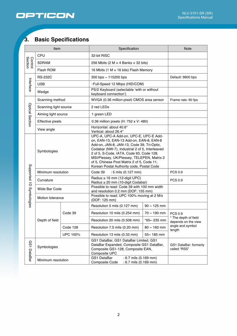
3. Basic Specifications Item Specification Note
Control
Section
CPU 32-bit RISC
SDRAM 256 Mbits (2 M × 4 Banks × 32 bits)
Flash ROM 16 Mbits (1 M × 16 bits) Flash Memory
Interface
RS-232C 300 bps ~ 115200 bps Default: 9600 bps
USB ・Full-Speed 12 Mbps (HID/COM)
Wedge PS/2 Keyboard (selectable ʻwith or without keyboard connectionʼ)
Optical Section
Scanning method WVGA (0.36 million-pixel) CMOS area sensor Frame rate: 60 fps
Scanning light source 2 red LEDs
Aiming light source 1 green LED
Effective pixels 0.36 million pixels (H: 752 x V: 480)
View angle Horizontal: about 40.6° Vertical: about 26.4°
Supported 1D Sym
bologies
Symbologies
UPC-A, UPC-A Add-on, UPC-E, UPC-E Add-on, EAN-13, EAN-13 Add-on, EAN-8, EAN-8 Add-on, JAN-8, JAN-13, Code 39, Tri-Optic, Codabar (NW-7), Industrial 2 of 5, Interleaved 2 of 5, S-Code, IATA, Code 93, Code 128, MSI/Plessey, UK/Plessey, TELEPEN, Matrix 2 of 5, Chinese Post Matrix 2 of 5, Code 11, Korean Postal Authority code, Postal Code
Minimum resolution Code 39 : 5 mils (0.127 mm) PCS 0.9
Curvature Radius ≥ 16 mm (12-digit UPC) Radius ≥ 20 mm (10-digit Codabar) PCS 0.9
Wide Bar Code Possible to read: Code 39 with 100 mm width and resolution 0.2 mm (DOF: 155 mm)
Motion tolerance Possible to read: UPC 100% moving at 2 M/s (DOF: 125 mm)
Depth of field
Code 39
Resolution 5 mils (0.127 mm) 90 ~ 125 mm
Resolution 10 mils (0.254 mm) 70 ~ 190 mm PCS 0.9 * The depth of field depends on the view angle and symbol length
Resolution 20 mils (0.508 mm) *65~ 235 mm
Code 128 Resolution 7.5 mils (0.20 mm) 80 ~ 160 mm
UPC 100% Resolution 13 mils (0.33 mm) 55~ 185 mm
GS1 D
ataBar
Symbologies
GS1 DataBar, GS1 DataBar Limited, GS1 DataBar Expanded, Composite GS1 DataBar, Composite GS1-128, Composite EAN, Composite UPC
GS1 DataBar: formerly called “RSS”
Minimum resolution GS1 DataBar Composite Code
: 6.7 mils (0.169 mm) : 6.7 mils (0.169 mm)
NLV-3101-SR (SR) Specifications Manual
3
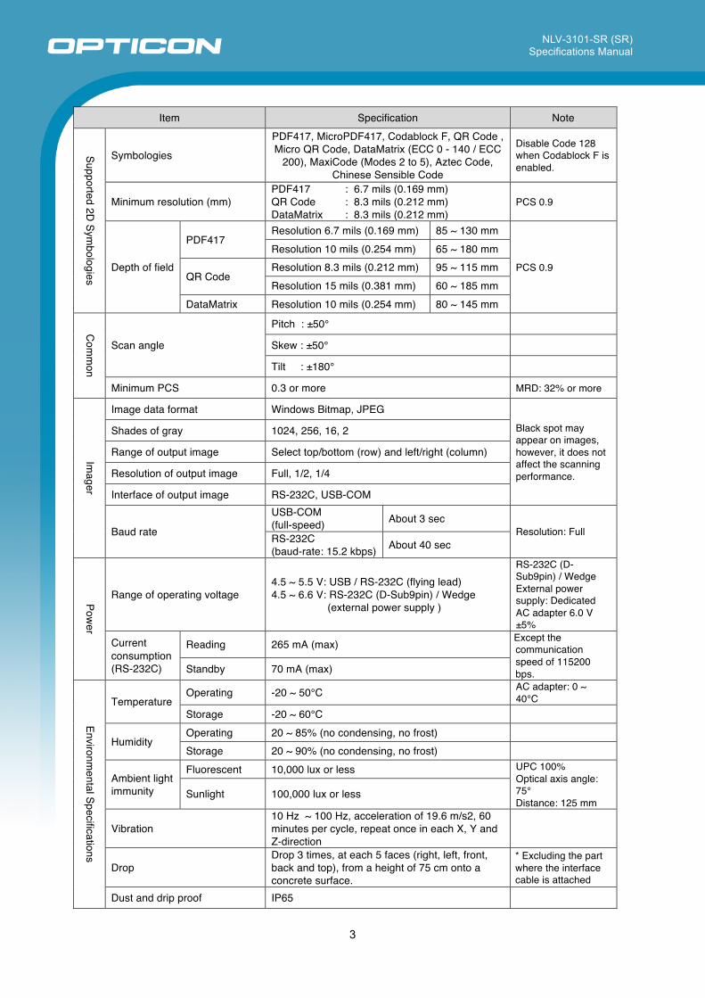
Item Specification Note
Supported 2D Sym
bologies
Symbologies
PDF417, MicroPDF417, Codablock F, QR Code , Micro QR Code, DataMatrix (ECC 0 - 140 / ECC
200), MaxiCode (Modes 2 to 5), Aztec Code, Chinese Sensible Code
Disable Code 128 when Codablock F is enabled.
Minimum resolution (mm) PDF417 QR Code DataMatrix
: 6.7 mils (0.169 mm) : 8.3 mils (0.212 mm) : 8.3 mils (0.212 mm)
PCS 0.9
Depth of field
PDF417 Resolution 6.7 mils (0.169 mm) 85 ~ 130 mm
PCS 0.9
Resolution 10 mils (0.254 mm) 65 ~ 180 mm
QR Code Resolution 8.3 mils (0.212 mm) 95 ~ 115 mm Resolution 15 mils (0.381 mm) 60 ~ 185 mm
DataMatrix Resolution 10 mils (0.254 mm) 80 ~ 145 mm
Com
mon
Scan angle
Pitch : ±50°
Skew : ±50°
Tilt : ±180°
Minimum PCS 0.3 or more MRD: 32% or more
Imager
Image data format Windows Bitmap, JPEG Black spot may appear on images, however, it does not affect the scanning performance.
Shades of gray 1024, 256, 16, 2
Range of output image Select top/bottom (row) and left/right (column)
Resolution of output image Full, 1/2, 1/4
Interface of output image RS-232C, USB-COM
Baud rate
USB-COM (full-speed) About 3 sec
Resolution: Full RS-232C (baud-rate: 15.2 kbps) About 40 sec
Power
Range of operating voltage 4.5 ~ 5.5 V: USB / RS-232C (flying lead) 4.5 ~ 6.6 V: RS-232C (D-Sub9pin) / Wedge
(external power supply )
RS-232C (D-Sub9pin) / Wedge External power supply: Dedicated AC adapter 6.0 V ±5%
Current consumption (RS-232C)
Reading 265 mA (max) Except the communication speed of 115200 bps. Standby 70 mA (max)
Environmental Specifications
Temperature Operating -20 ~ 50°C AC adapter: 0 ~
40°C Storage -20 ~ 60°C
Humidity Operating 20 ~ 85% (no condensing, no frost)
Storage 20 ~ 90% (no condensing, no frost)
Ambient light immunity
Fluorescent 10,000 lux or less UPC 100% Optical axis angle: 75° Distance: 125 mm
Sunlight 100,000 lux or less
Vibration 10 Hz ~ 100 Hz, acceleration of 19.6 m/s2, 60 minutes per cycle, repeat once in each X, Y and Z-direction
Drop Drop 3 times, at each 5 faces (right, left, front, back and top), from a height of 75 cm onto a concrete surface.
* Excluding the part where the interface cable is attached
Dust and drip proof IP65
NLV-3101-SR (SR) Specifications Manual
4
Item Specification Note
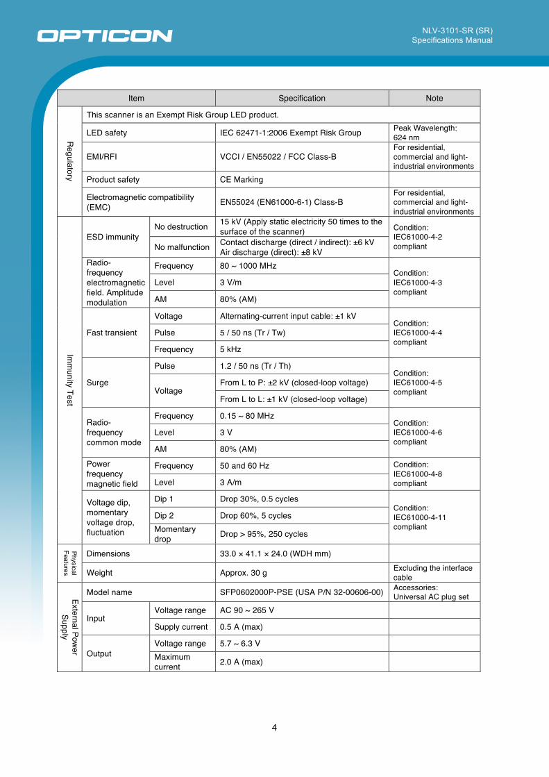
Regulatory
This scanner is an Exempt Risk Group LED product.
LED safety IEC 62471-1:2006 Exempt Risk Group Peak Wavelength: 624 nm
EMI/RFI VCCI / EN55022 / FCC Class-B For residential, commercial and light-industrial environments
Product safety CE Marking
Electromagnetic compatibility (EMC) EN55024 (EN61000-6-1) Class-B
For residential, commercial and light-industrial environments
Imm
unity Test
ESD immunity No destruction 15 kV (Apply static electricity 50 times to the
surface of the scanner) Condition: IEC61000-4-2 compliant No malfunction Contact discharge (direct / indirect): ±6 kV
Air discharge (direct): ±8 kV Radio-frequency electromagnetic field. Amplitude modulation
Frequency 80 ~ 1000 MHz Condition: IEC61000-4-3 compliant
Level 3 V/m
AM 80% (AM)
Fast transient
Voltage Alternating-current input cable: ±1 kV Condition: IEC61000-4-4 compliant
Pulse 5 / 50 ns (Tr / Tw)
Frequency 5 kHz
Surge
Pulse 1.2 / 50 ns (Tr / Th) Condition: IEC61000-4-5 compliant Voltage
From L to P: ±2 kV (closed-loop voltage)
From L to L: ±1 kV (closed-loop voltage)
Radio-frequency common mode
Frequency 0.15 ~ 80 MHz Condition: IEC61000-4-6 compliant
Level 3 V
AM 80% (AM)
Power frequency magnetic field
Frequency 50 and 60 Hz Condition: IEC61000-4-8 compliant Level 3 A/m
Voltage dip, momentary voltage drop, fluctuation
Dip 1 Drop 30%, 0.5 cycles Condition: IEC61000-4-11 compliant
Dip 2 Drop 60%, 5 cycles Momentary drop Drop > 95%, 250 cycles
Physical Features
Dimensions 33.0 × 41.1 × 24.0 (WDH mm)
Weight Approx. 30 g Excluding the interface cable
External Power
Supply
Model name SFP0602000P-PSE (USA P/N 32-00606-00) Accessories: Universal AC plug set
Input Voltage range AC 90 ~ 265 V
Supply current 0.5 A (max)
Output Voltage range 5.7 ~ 6.3 V Maximum current 2.0 A (max)
NLV-3101-SR (SR) Specifications Manual
5
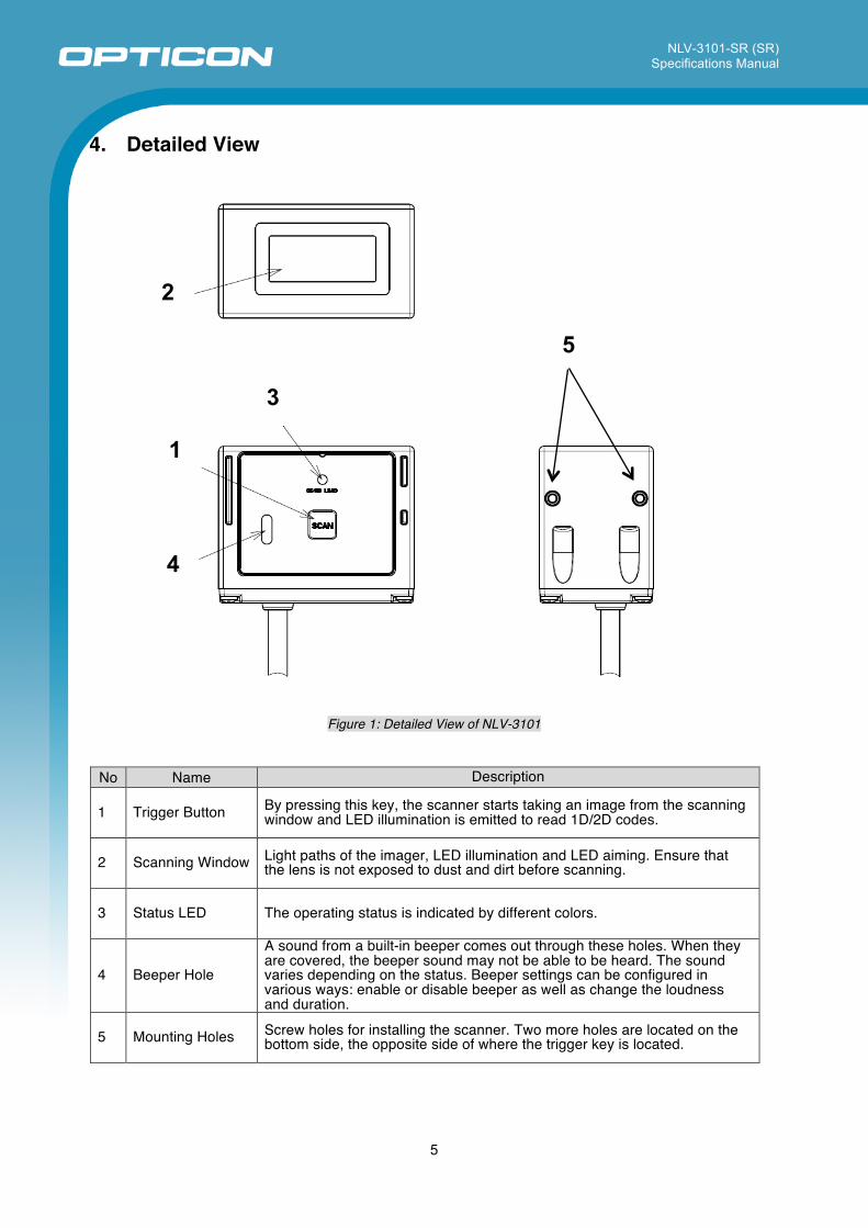
4. Detailed View
Figure 1: Detailed View of NLV-3101
No Name Description
1 Trigger Button By pressing this key, the scanner starts taking an image from the scanning window and LED illumination is emitted to read 1D/2D codes.
2 Scanning Window Light paths of the imager, LED illumination and LED aiming. Ensure that the lens is not exposed to dust and dirt before scanning.
3 Status LED The operating status is indicated by different colors.
4 Beeper Hole
A sound from a built-in beeper comes out through these holes. When they are covered, the beeper sound may not be able to be heard. The sound varies depending on the status. Beeper settings can be configured in various ways: enable or disable beeper as well as change the loudness and duration.
5 Mounting Holes Screw holes for installing the scanner. Two more holes are located on the bottom side, the opposite side of where the trigger key is located.
1
2
3
4
5
NLV-3101-SR (SR) Specifications Manual
6
5. Electrical Specifications
5.1. AC Adapter Specifications For RS-232C (D-Sub 9pin) and Wedge PS/2 models
5.1.1. Input Specifications Power supply voltage : AC 90 ~ 265 V Power supply frequency : 47 ~ 63 Hz Maximum current : 0.5 A (max)
5.1.2. Output Specifications Output voltage : 6.0 V ±5% / Output current: 0 ~ 2.0 A (max) Power ripple : 100 mVp-p (max, rated load)
5.2. Wedge PS/2 Power Supply (Host) Input power supply voltage : DC 5.0 V Range of working voltage : 4.5 ~ 5.5 V Power ripple : 100 mVp-p max (10 ~ 100 kHz, power supply voltage 5.0 V) Current consumption : 250 mA (max) without main power supply (AC adapter)
5 mA (max) in standby state with main power supply (AC adapter) * Current consumption from the main power supply in standby state: 155 mA (max) * Current consumption from the main power supply during reading operation: 305 mA (max) * Keyboard operation is possible when the main power supply is off. * The current consumption was measured at 25°C.
5.3. USB Power Supply Power supply : 500 mA High-Power Current consumption : 85 mA (max) in stand-by mode : 400 mA (max) during reading operation * The current consumption was measured at 25°C.
NLV-3101-SR (SR) Specifications Manual
7
6. Interface Specifications The NLV-3101 supports four types of interfaces; RS-232C, USB-HID, USB-COM and Wedge PS/2.
6.1. RS-232C The RS-232C interface has two specifications for connecting to the host: D-Sub9pin with DC jack and (10 wires) with sequencer signals.
Communication Setting
Baud rate : 300 ~ 115200 bps Data length : 7 / 8 bits Parity bits : No / Even / Odd parity Stop bits : 1 / 2 bit * Multi byte character data or images can be transmitted via RS-232C interface.
Signal Level: signal names are based on the signals transmitted from the scanner to the host.
Signal Name IN/OUT Voltage(V)
Mark Space TxD OUT -5 ~ -15 +5 ~ +15 RxD IN -3 ~ -15 +3 ~ +15 RTS OUT -5 ~ -15 +5 ~ +15 CTS IN -3 ~ -15 +3 ~ +15
Signal Level: sequencer signals (Flying lead (no connector) cable specification only)
Signal Name IN/OUT Voltage(V)
L level Space / ON External trigger IN -0.3 ~ 0.6 V 3 V ~ Vcc +0.3 V
OK OUT 0.3 V / 10 mA OC output / Vcc +0.3 V NG OUT 0.3 V / 10 mA OC output / Vcc +0.3 V
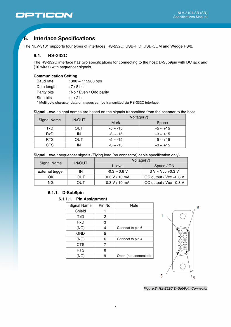
6.1.1. D-Sub9pin
6.1.1.1. Pin Assignment Signal Name Pin No. Note
Shield 1 TxD 2 RxD 3 (NC) 4 Connect to pin 6 GND 5 (NC) 6 Connect to pin 4 CTS 7 RTS 8 (NC) 9 Open (not connected)
Figure 2: RS-232C D-Sub9pin Connector
NLV-3101-SR (SR) Specifications Manual
8
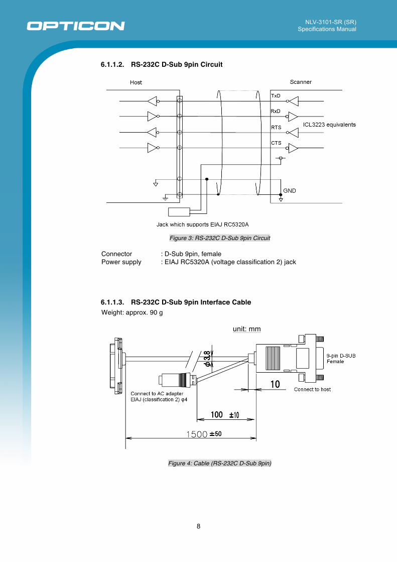
6.1.1.2. RS-232C D-Sub 9pin Circuit
Figure 3: RS-232C D-Sub 9pin Circuit
Connector : D-Sub 9pin, female Power supply : EIAJ RC5320A (voltage classification 2) jack
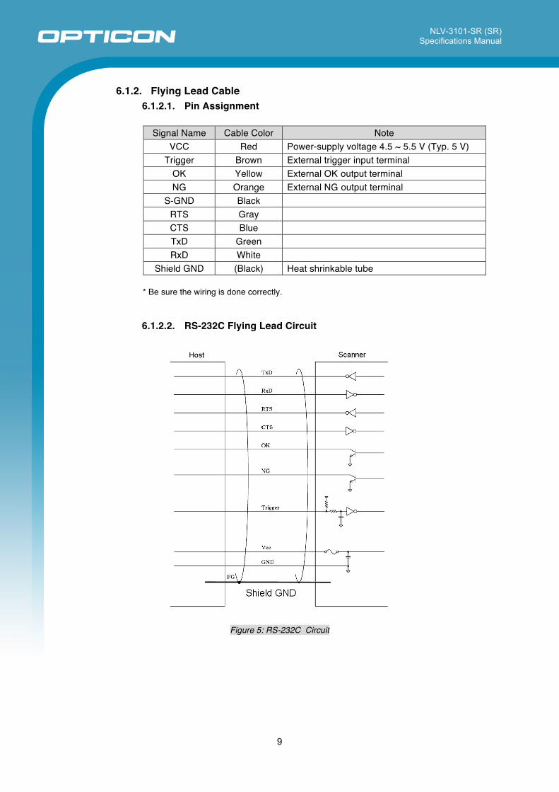
6.1.1.3. RS-232C D-Sub 9pin Interface Cable Weight: approx. 90 g
unit: mm
Figure 4: Cable (RS-232C D-Sub 9pin)
NLV-3101-SR (SR) Specifications Manual
9
6.1.2. Flying Lead Cable 6.1.2.1. Pin Assignment
Signal Name Cable Color Note
VCC Red Power-supply voltage 4.5 ~ 5.5 V (Typ. 5 V) Trigger Brown External trigger input terminal
OK Yellow External OK output terminal NG Orange External NG output terminal
S-GND Black RTS Gray CTS Blue TxD Green RxD White
Shield GND (Black) Heat shrinkable tube * Be sure the wiring is done correctly.
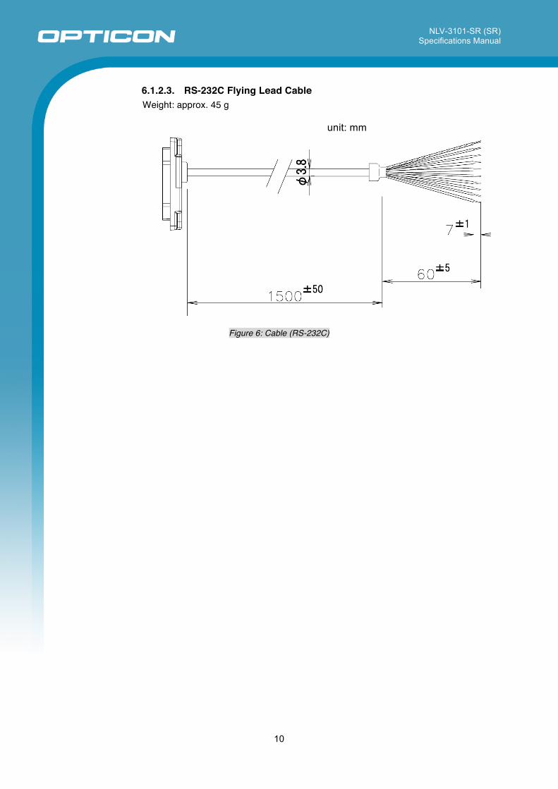
6.1.2.2. RS-232C Flying Lead Circuit
Figure 5: RS-232C Circuit
NLV-3101-SR (SR) Specifications Manual
10
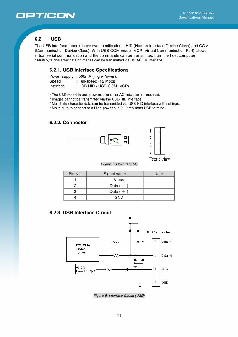
6.1.2.3. RS-232C Flying Lead Cable Weight: approx. 45 g
unit: mm
Figure 6: Cable (RS-232C)
NLV-3101-SR (SR) Specifications Manual
11
6.2. USB The USB interface models have two specifications: HID (Human Interface Device Class) and COM (Communication Device Class). With USB-COM model, VCP (Virtual Communication Port) allows virtual serial communication and the commands can be transmitted from the host computer. * Multi byte character data or images can be transmitted via USB-COM interface.
6.2.1. USB Interface Specifications Power supply : 500mA (High-Power). Speed : Full-speed (12 Mbps) Interface : USB-HID / USB-COM (VCP)
* The USB model is bus powered and no AC adapter is required. * Images cannot be transmitted via the USB-HID interface. * Multi byte character data can be transmitted via USB-HID interface with settings. * Make sure to connect to a High-power bus (500 mA max) USB terminal.
6.2.2. Connector
Figure 7: USB Plug (A)
Pin No. Signal name Note
1 V bus 2 Data ( ‐ ) 3 Data ( + ) 4 GND
6.2.3. USB Interface Circuit
Figure 8: Interface Circuit (USB)
NLV-3101-SR (SR) Specifications Manual
12
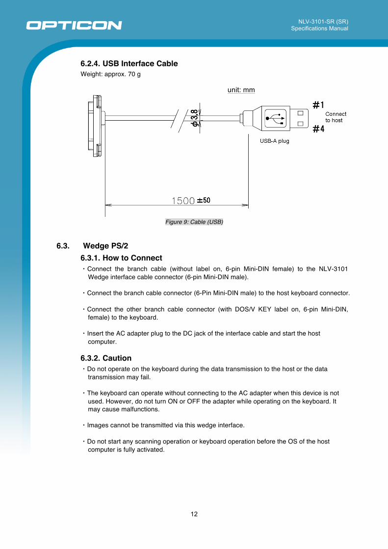
6.2.4. USB Interface Cable Weight: approx. 70 g
unit: mm
Figure 9: Cable (USB)
6.3. Wedge PS/2 6.3.1. How to Connect ・Connect the branch cable (without label on, 6-pin Mini-DIN female) to the NLV-3101
Wedge interface cable connector (6-pin Mini-DIN male).
・Connect the branch cable connector (6-Pin Mini-DIN male) to the host keyboard connector. ・Connect the other branch cable connector (with DOS/V KEY label on, 6-pin Mini-DIN,
female) to the keyboard.
・Insert the AC adapter plug to the DC jack of the interface cable and start the host computer.
6.3.2. Caution ・Do not operate on the keyboard during the data transmission to the host or the data
transmission may fail. ・The keyboard can operate without connecting to the AC adapter when this device is not
used. However, do not turn ON or OFF the adapter while operating on the keyboard. It may cause malfunctions.
・Images cannot be transmitted via this wedge interface. ・Do not start any scanning operation or keyboard operation before the OS of the host
computer is fully activated.
NLV-3101-SR (SR) Specifications Manual
13
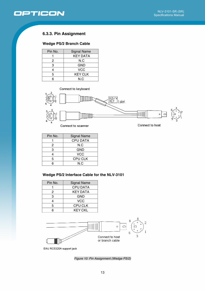
6.3.3. Pin Assignment Wedge PS/2 Branch Cable
Pin No. Signal Name 1 KEY DATA 2 N.C 3 GND 4 VCC 5 KEY CLK 6 N.C
Pin No. Signal Name
1 CPU DATA 2 N.C 3 GND 4 VCC 5 CPU CLK 6 N.C
Wedge PS/2 Interface Cable for the NLV-3101
Pin No. Signal Name 1 CPU DATA 2 KEY DATA 3 GND 4 VCC 5 CPU CLK 6 KEY CKL
Figure 10: Pin Assignment (Wedge PS/2)
NLV-3101-SR (SR) Specifications Manual
14
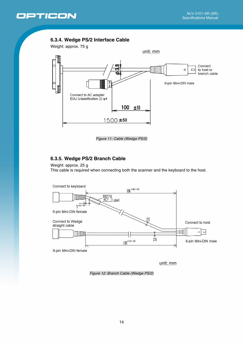
6.3.4. Wedge PS/2 Interface Cable Weight: approx. 75 g
unit: mm
Figure 11: Cable (Wedge PS/2)
6.3.5. Wedge PS/2 Branch Cable Weight: approx. 25 g This cable is required when connecting both the scanner and the keyboard to the host.
unit: mm
Figure 12: Branch Cable (Wedge PS/2)
NLV-3101-SR (SR) Specifications Manual
15
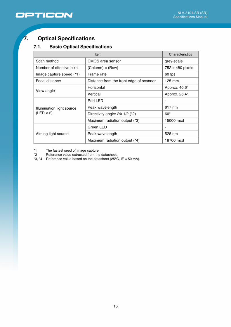
7. Optical Specifications 7.1. Basic Optical Specifications
Item Characteristics
Scan method CMOS area sensor grey-scale Number of effective pixel (Column) × (Row) 752 × 480 pixels Image capture speed (*1) Frame rate 60 fps Focal distance Distance from the front edge of scanner 125 mm
View angle Horizontal Approx. 40.6° Vertical Approx. 26.4°
Illumination light source (LED × 2)
Red LED - Peak wavelength 617 nm Directivity angle: 2Φ 1/2 (*2) 60° Maximum radiation output (*3) 15000 mcd
Aiming light source Green LED - Peak wavelength 528 nm Maximum radiation output (*4) 18700 mcd
*1 The fastest seed of image capture *2 Reference value extracted from the datasheet. *3, *4 Reference value based on the datasheet (25°C, IF = 50 mA).
NLV-3101-SR (SR) Specifications Manual
16
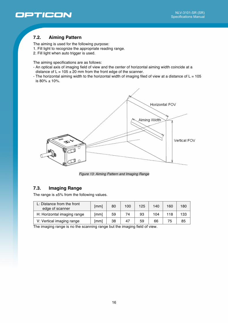
7.2. Aiming Pattern The aiming is used for the following purpose: 1. Fill light to recognize the appropriate reading range. 2. Fill light when auto trigger is used. The aiming specifications are as follows: - An optical axis of imaging field of view and the center of horizontal aiming width coincide at a
distance of L = 105 ± 20 mm from the front edge of the scanner. - The horizontal aiming width to the horizontal width of imaging filed of view at a distance of L = 105
is 80% ± 10%.
Figure 13: Aiming Pattern and Imaging Range
7.3. Imaging Range The range is ±5% from the following values.
L: Distance from the front edge of scanner [mm] 80 100 125 140 160 180
H: Horizontal imaging range [mm] 59 74 93 104 118 133 V: Vertical imaging range [mm] 38 47 59 66 75 85
The imaging range is no the scanning range but the imaging field of view.
NLV-3101-SR (SR) Specifications Manual
17
8. Technical Specifications Aim the green bar illumination at the center of a code to scan it. For long distance scanning, ambient light entering the angle of view may affect the scanning performance. The conditions for technical specifications are as follows, unless otherwise specified in each section.
<Conditions> Ambient Temperature and Humidity Room temperature, room humidity Ambient Light 100 ~200 lux (on the surface of a bar code) Angles Pitch: α = 0°, Skew: β = 15°, Tilt: γ = 0° Curvature R = ∞ Power Supply Voltage 5.0 V PCS (1D and 2D) 0.9 or higher Scanning Test Accept the performance with 90% or more success rate
for 10 tries of scan. One scan should be tested within 1 second.
Barcode Test Sample (1D and 2D) Specified below.
< Test chart > For 1D codes, OPTOELECTRONICS test samples For GS1 Databar, stacked codes and 2D codes, printed by a dedicated printer for bar code
NLV-3101-SR (SR) Specifications Manual
18
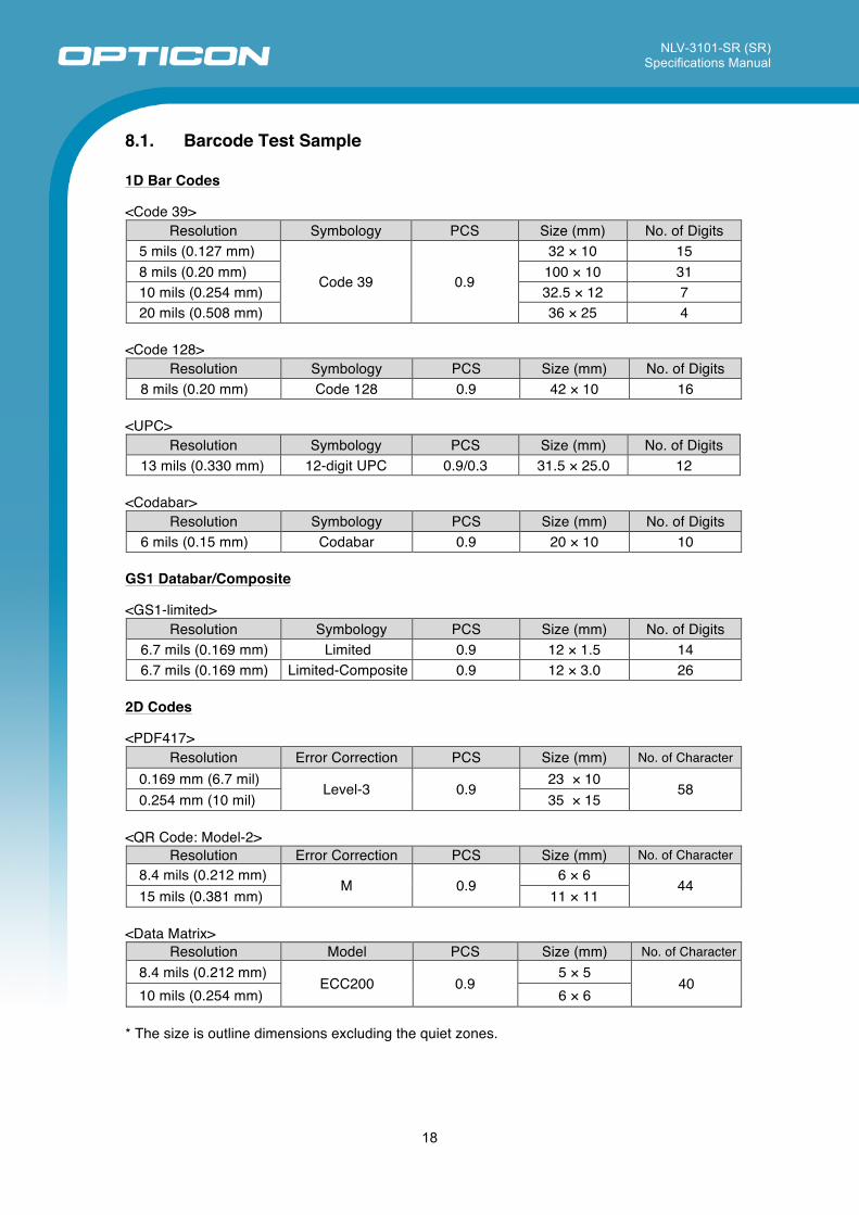
8.1. Barcode Test Sample
1D Bar Codes
<Code 39> Resolution Symbology PCS Size (mm) No. of Digits
5 mils (0.127 mm)
Code 39 0.9
32 × 10 15 8 mils (0.20 mm) 100 × 10 31 10 mils (0.254 mm) 32.5 × 12 7 20 mils (0.508 mm) 36 × 25 4
<Code 128>
Resolution Symbology PCS Size (mm) No. of Digits 8 mils (0.20 mm) Code 128 0.9 42 × 10 16
<UPC>
Resolution Symbology PCS Size (mm) No. of Digits 13 mils (0.330 mm) 12-digit UPC 0.9/0.3 31.5 × 25.0 12
<Codabar>
Resolution Symbology PCS Size (mm) No. of Digits 6 mils (0.15 mm) Codabar 0.9 20 × 10 10
GS1 Databar/Composite <GS1-limited>
Resolution Symbology PCS Size (mm) No. of Digits 6.7 mils (0.169 mm) Limited 0.9 12 × 1.5 14 6.7 mils (0.169 mm) Limited-Composite 0.9 12 × 3.0 26
2D Codes
<PDF417>
Resolution Error Correction PCS Size (mm) No. of Character 0.169 mm (6.7 mil)
Level-3 0.9 23 × 10
58 0.254 mm (10 mil) 35 × 15
<QR Code: Model-2>
Resolution Error Correction PCS Size (mm) No. of Character 8.4 mils (0.212 mm)
M 0.9 6 × 6
44 15 mils (0.381 mm) 11 × 11
<Data Matrix>
Resolution Model PCS Size (mm) No. of Character 8.4 mils (0.212 mm)
ECC200 0.9 5 × 5
40 10 mils (0.254 mm) 6 × 6
* The size is outline dimensions excluding the quiet zones.
NLV-3101-SR (SR) Specifications Manual
19
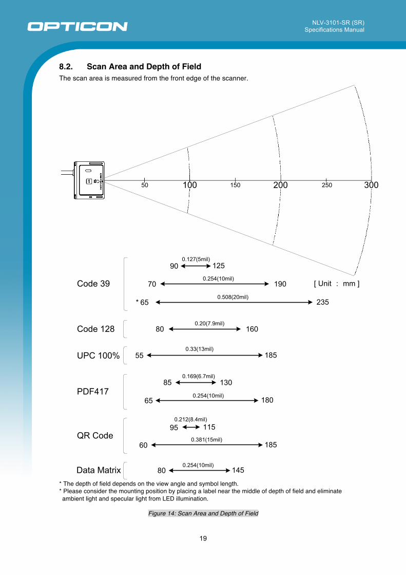
8.2. Scan Area and Depth of Field The scan area is measured from the front edge of the scanner.
* The depth of field depends on the view angle and symbol length. * Please consider the mounting position by placing a label near the middle of depth of field and eliminate ambient light and specular light from LED illumination.
Figure 14: Scan Area and Depth of Field
80 160
185
13085
18065
95 115
60 185
80 145
Code 128
UPC 100%
PDF417
QR Code
Data Matrix
0.20(7.9mil)
0.33(13mil)
0.169(6.7mil)
0.254(10mil)
0.212(8.4mil)
0.381(15mil)
0.254(10mil)
55
70 190
235
Code 390.254(10mil)
0.508(20mil)
[ Unit : mm ]
* 65
0.127(5mil)90 125
50 100 150 200 250 300
NLV-3101-SR (SR) Specifications Manual
20
8.3. Printed Contrast Signal (PCS) 0.3 or higher
<Conditions> MRD : 32% and higher
(70% or higher reflectivity of space and quiet zone) Distance : 125 mm from the front edge of the scanner Bar Code Sample : UPC specified in Chapter 8.1. (Resolution: 0.33 mm, PCS: 0.3)
MRD = Minimum reflectance of white bar - Maximum reflectance of black bar
PCS = Reflectance of white bar‐Reflectance of black bar
Reflectance of white bar
8.4. Minimum Resolution 1D Code : 5 mils (0.127 mm) Code 39 specified in Chapter 8.1 GS1-Databar : 6.7 mils (0.169 mm) GS1 Databar Limited specified in Chapter 8.1 Stacked Code : 6.7 mils (0.169 mm) PDF417, GS1 Databar Limited Composite specified in Chapter 8.1 2D Code : 8.4 mils (0.212 mm) QR Code and Data Matrix specified in Chapter 8.1
<Conditions> Bar Code Sample : The above codes specified in Chapter 8.1 Distance : 100 mm from the front edge of the scanner Angle : α = 0°, β =+15°, γ = 0° Curvature : R = ∞
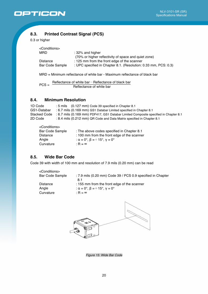
8.5. Wide Bar Code Code 39 with width of 100 mm and resolution of 7.9 mils (0.20 mm) can be read
<Conditions> Bar Code Sample : 7.9 mils (0.20 mm) Code 39 / PCS 0.9 specified in Chapter
8.1 Distance : 155 mm from the front edge of the scanner Angle : α = 0°, β =+15°, γ = 0° Curvature : R = ∞
Figure 15: Wide Bar Code
NLV-3101-SR (SR) Specifications Manual
21
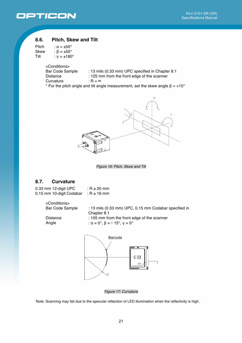
8.6. Pitch, Skew and Tilt Pitch : α = ±50° Skew : β = ±50° Tilt : γ = ±180°
<Conditions> Bar Code Sample : 13 mils (0.33 mm) UPC specified in Chapter 8.1 Distance : 125 mm from the front edge of the scanner Curvature : R = ∞ * For the pitch angle and tilt angle measurement, set the skew angle β = +15°
Figure 16: Pitch, Skew and Tilt
8.7. Curvature 0.33 mm 12-digit UPC : R ≥ 20 mm 0.15 mm 10-digit Codabar : R ≥ 16 mm
<Conditions> Bar Code Sample : 13 mils (0.33 mm) UPC, 0.15 mm Codabar specified in
Chapter 8.1 Distance : 105 mm from the front edge of the scanner Angle : α = 0°, β =+15°, γ = 0°
Figure 17: Curvature
Note: Scanning may fail due to the specular reflection of LED illumination when the reflectivity is high.
Barcode
NLV-3101-SR (SR) Specifications Manual
22
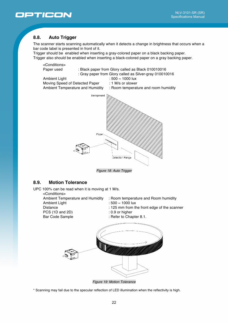
8.8. Auto Trigger The scanner starts scanning automatically when it detects a change in brightness that occurs when a bar code label is presented in front of it. Trigger should be enabled when inserting a gray-colored paper on a black backing paper. Trigger also should be enabled when inserting a black-colored paper on a gray backing paper.
<Conditions> Paper used : Black paper from Glory called as Black 010010016 : Gray paper from Glory called as Silver-gray 010010016 Ambient Light : 500 ~ 1000 lux Moving Speed of Detected Paper : 1 M/s or slower Ambient Temperature and Humidity : Room temperature and room humidity
Figure 18: Auto Trigger
8.9. Motion Tolerance UPC 100% can be read when it is moving at 1 M/s.
<Conditions> Ambient Temperature and Humidity : Room temperature and Room humidity Ambient Light : 500 ~ 1000 lux Distance : 125 mm from the front edge of the scanner PCS (1D and 2D) : 0.9 or higher Bar Code Sample : Refer to Chapter 8.1.
Figure 19: Motion Tolerance
* Scanning may fail due to the specular reflection of LED illumination when the reflectivity is high.
NLV-3101-SR (SR) Specifications Manual
23
9. Environmental Specifications 9.1. Temperature Scanning performance is guaranteed when the range of ambient temperature around the scanner is the following values:
Operating Temperature : -20 ~ 50 °C Storage Temperature : -20 ~ 60 °C
<Conditions> Bar Code Sample : 13 mils (0.33 mm) UPC specified in Chapter 8.1 Distance : 125 mm from the front edge of the scanner Angle : α = 0°, β =+15°, γ = 0° Curvature : R = ∞ Scanning Test : Read at intervals of 300 ms
* When you attach this scanner to a place with few crevices, or the bad place of breathability, please check the circumference temperature of this scanner.
9.2. Humidity Scanning performance is guaranteed when the range of ambient humidity around the scanner is the following values:
Operating Humidity : 20 ~ 85% RH (no condensation, no frost) Storage Humidity : 20 ~ 90% RH (no condensation, no frost)
<Conditions> Bar Code Sample : 13 mils (0.33 mm) UPC specified in Chapter 8.1 Distance : 125 mm from the front edge of the scanner Angle : α = 0°, β =+15°, γ = 0° Curvature : R = ∞
NLV-3101-SR (SR) Specifications Manual
24
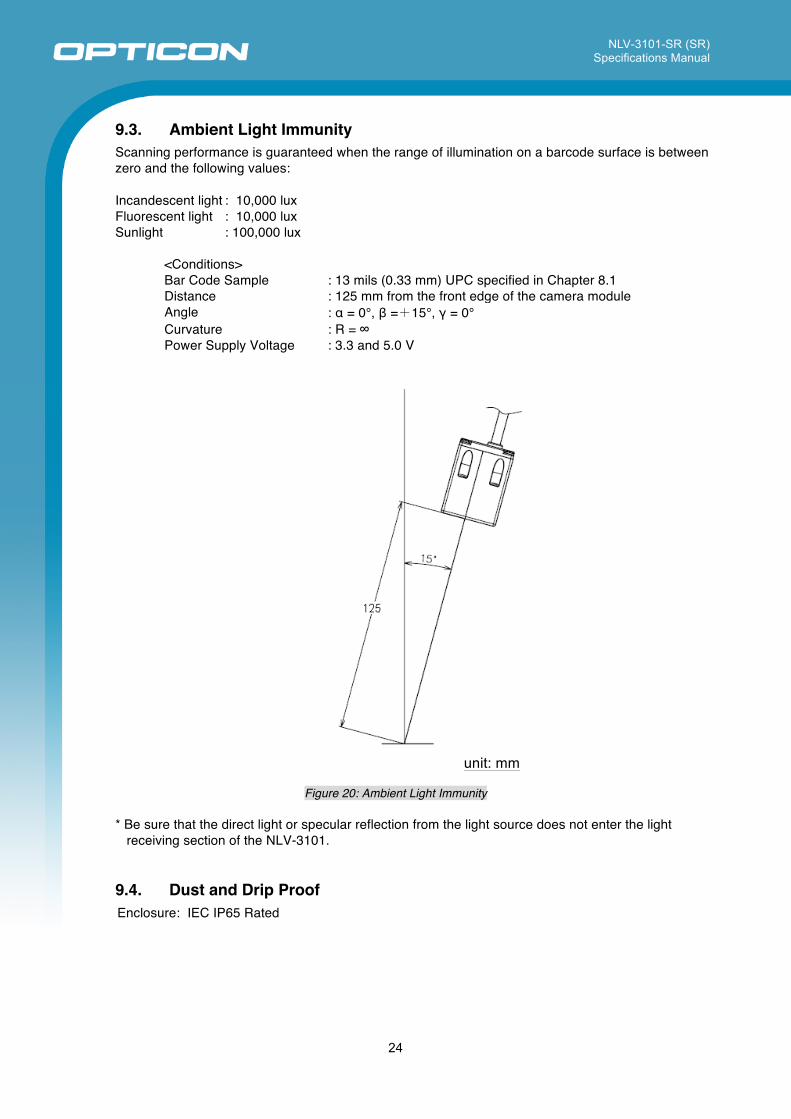
9.3. Ambient Light Immunity Scanning performance is guaranteed when the range of illumination on a barcode surface is between zero and the following values:
Incandescent light : 10,000 lux Fluorescent light : 10,000 lux Sunlight : 100,000 lux
<Conditions> Bar Code Sample : 13 mils (0.33 mm) UPC specified in Chapter 8.1 Distance : 125 mm from the front edge of the camera module Angle : α = 0°, β =+15°, γ = 0° Curvature : R = ∞ Power Supply Voltage : 3.3 and 5.0 V
unit: mm
Figure 20: Ambient Light Immunity
* Be sure that the direct light or specular reflection from the light source does not enter the light
receiving section of the NLV-3101.
9.4. Dust and Drip Proof Enclosure: IEC IP65 Rated
NLV-3101-SR (SR) Specifications Manual
25
9.5. Cable Strength There shall be no sign of malfunction after the following cable strength test. Cable Strength Test: Affix the scanner to an immovable object and pull it using a force of 24.5 N (2.5 kgf static loading) for 1 second. Repeat this 20 times continuously.
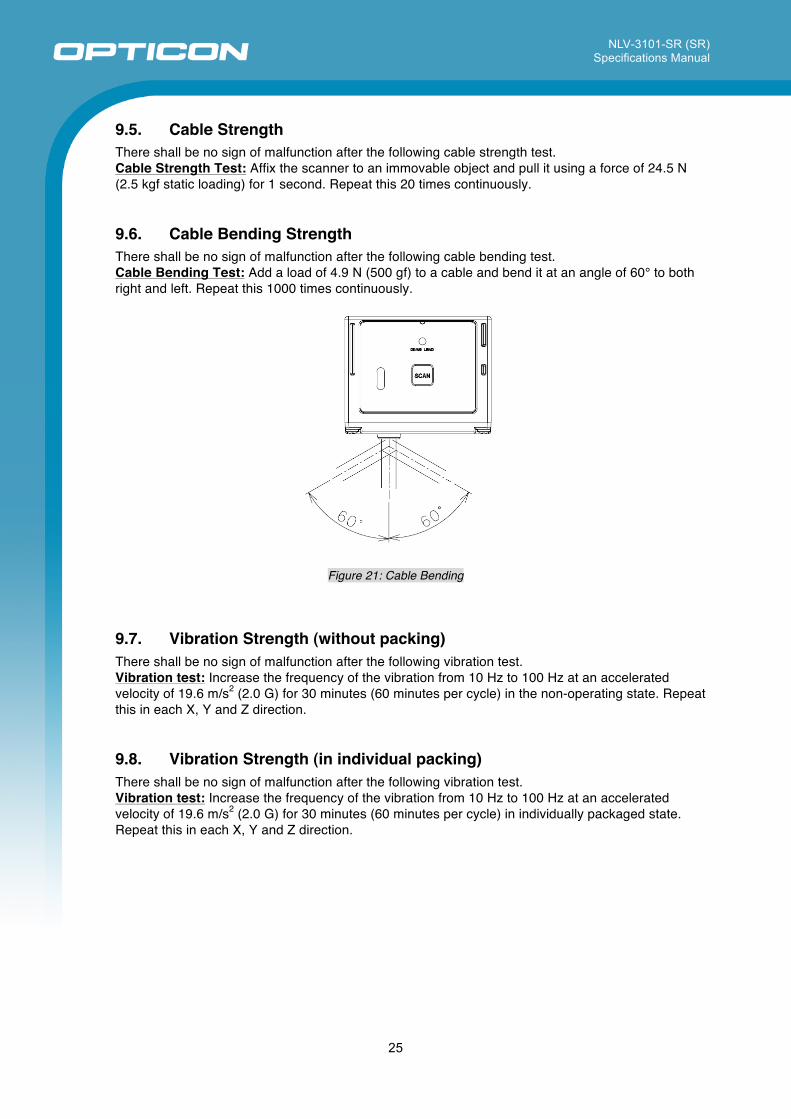
9.6. Cable Bending Strength There shall be no sign of malfunction after the following cable bending test. Cable Bending Test: Add a load of 4.9 N (500 gf) to a cable and bend it at an angle of 60° to both right and left. Repeat this 1000 times continuously.
Figure 21: Cable Bending
9.7. Vibration Strength (without packing) There shall be no sign of malfunction after the following vibration test. Vibration test: Increase the frequency of the vibration from 10 Hz to 100 Hz at an accelerated velocity of 19.6 m/s2 (2.0 G) for 30 minutes (60 minutes per cycle) in the non-operating state. Repeat this in each X, Y and Z direction.
9.8. Vibration Strength (in individual packing) There shall be no sign of malfunction after the following vibration test. Vibration test: Increase the frequency of the vibration from 10 Hz to 100 Hz at an accelerated velocity of 19.6 m/s2 (2.0 G) for 30 minutes (60 minutes per cycle) in individually packaged state. Repeat this in each X, Y and Z direction.
NLV-3101-SR (SR) Specifications Manual
26
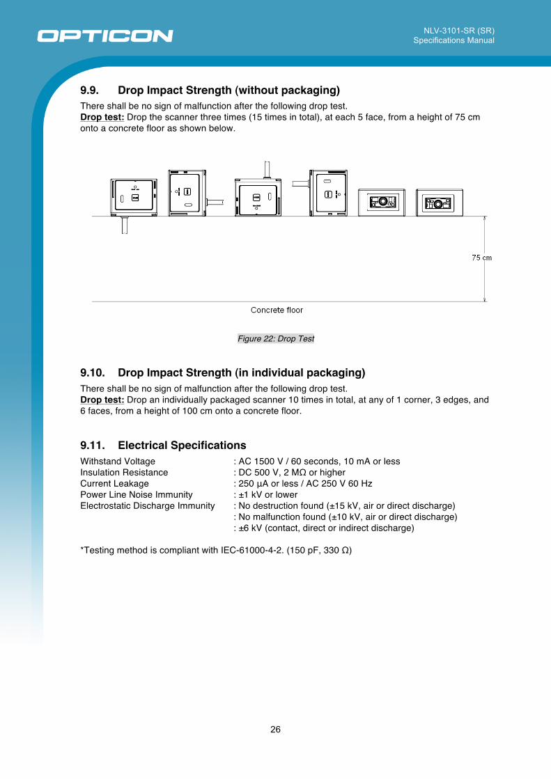
9.9. Drop Impact Strength (without packaging) There shall be no sign of malfunction after the following drop test. Drop test: Drop the scanner three times (15 times in total), at each 5 face, from a height of 75 cm onto a concrete floor as shown below.
Figure 22: Drop Test
9.10. Drop Impact Strength (in individual packaging) There shall be no sign of malfunction after the following drop test. Drop test: Drop an individually packaged scanner 10 times in total, at any of 1 corner, 3 edges, and 6 faces, from a height of 100 cm onto a concrete floor.
9.11. Electrical Specifications Withstand Voltage : AC 1500 V / 60 seconds, 10 mA or less Insulation Resistance : DC 500 V, 2 MΩ or higher Current Leakage : 250 μA or less / AC 250 V 60 Hz Power Line Noise Immunity : ±1 kV or lower Electrostatic Discharge Immunity : No destruction found (±15 kV, air or direct discharge) : No malfunction found (±10 kV, air or direct discharge) : ±6 kV (contact, direct or indirect discharge)
*Testing method is compliant with IEC-61000-4-2. (150 pF, 330 Ω)
NLV-3101-SR (SR) Specifications Manual
27
This device complies with part 15 of the FCC Rules. Operation is subject to the following two conditions: ( 1 ) this device may not cause harmful Interference, and ( 2 ) this device must accept any interference received, including interference that may cause undesired operation.
10. Regulatory Compliance 10.1. LED Safety IEC 62471-1:2006 Exempt Risk Group
10.2. EMC EN55022 EN55024 FCC Part 15 Subpart B Class B
VCCI Class B
11. RoHS The NLV-3101 is compliant with RoHS.
RoHS: The restriction of the use of certain hazardous substances in electrical and electronic equipment, 2002/95/EC
This is a Class B product, to be used in a domestic environment, based on the Technical Requirement of the Voluntary Control Council for Interference from Information Technology Equipment (VCCI). If this is used near a radio or television receiver in a domestic environment, it may cause radio interference.
NLV-3101-SR (SR) Specifications Manual
28
12. Reliability MTBF (Mean Time Between Failures) 50,000 hours Note: The reliability of the NLV-3101 is guaranteed as far as it is operated under normal operating conditions in the
range of advised operating temperature and without excessive electrical or mechanical shock. 13. Precautions Handle this product carefully. Do not deliberately subject it to any of the following.
13.1. Shock • Do not throw or drop the imager. • Do not place heavy objects on the cables.
13.2. Temperature Conditions • Do not use the imager at temperatures outside the specified range. • Do not pour boiling water on the imager. • Do not throw the imager into the fire. • Do not forcibly bend the cables at low temperatures.
13.3. Foreign Materials • Do not subject the imager to chemicals.
13.4. Other • Do not plug/unplug the connectors before disconnecting the power. • Do not disassemble this product. • Do not place the product near a radio or a TV receiver, as the imager may cause reception
problems. • The imager may be damaged by voltage drops.
NLV-3101-SR (SR) Specifications Manual
29
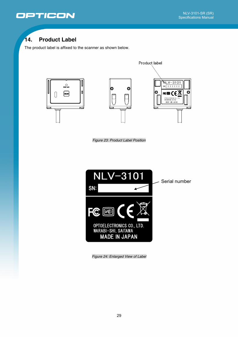
14. Product Label The product label is affixed to the scanner as shown below.
Figure 23: Product Label Position
Figure 24: Enlarged View of Label
Serial number
NLV-3101-SR (SR) Specifications Manual
30
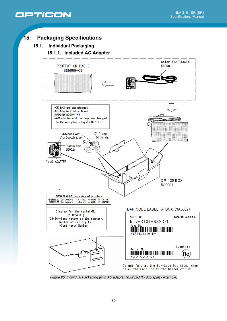
15. Packaging Specifications 15.1. Individual Packaging
15.1.1. Included AC Adapter
Figure 25: Individual Packaging (with AC adapter RS-232C (D-Sub 9pin) - example)
NLV-3101-SR (SR) Specifications Manual
31
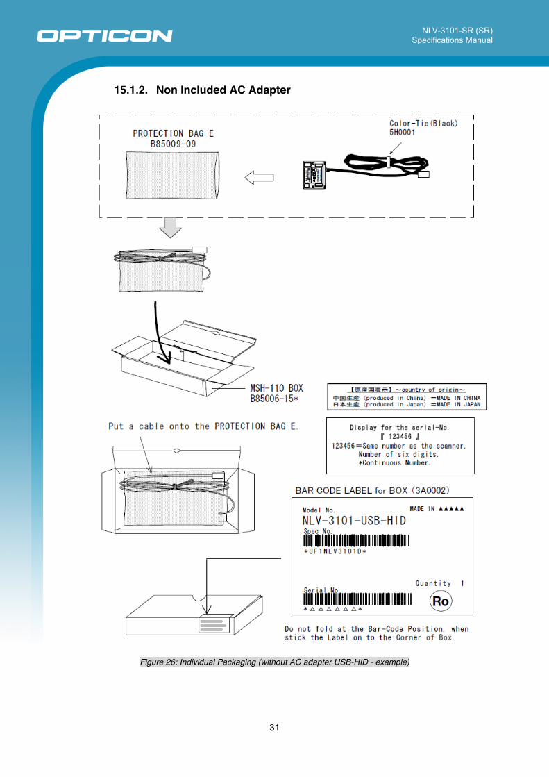
15.1.2. Non Included AC Adapter
Figure 26: Individual Packaging (without AC adapter USB-HID - example)
NLV-3101-SR (SR) Specifications Manual
32
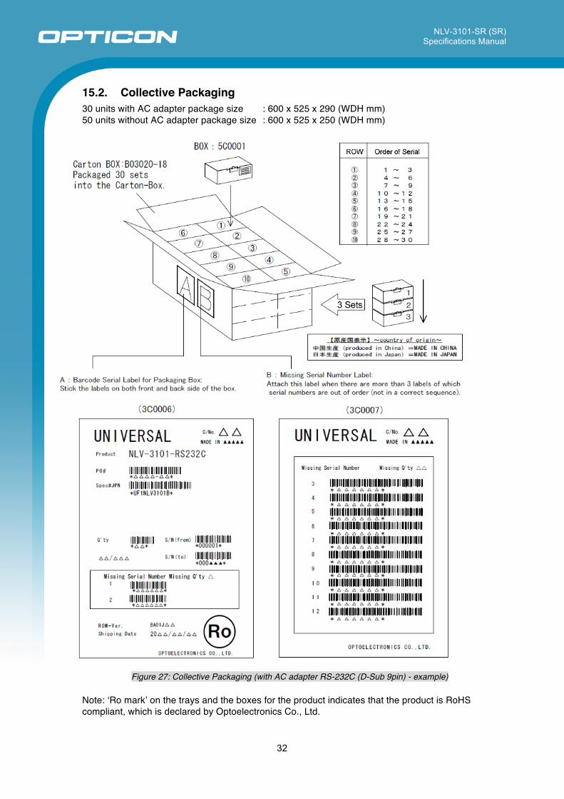
15.2. Collective Packaging 30 units with AC adapter package size : 600 x 525 x 290 (WDH mm) 50 units without AC adapter package size : 600 x 525 x 250 (WDH mm)
Figure 27: Collective Packaging (with AC adapter RS-232C (D-Sub 9pin) - example)
Note: ʻRo markʼ on the trays and the boxes for the product indicates that the product is RoHS compliant, which is declared by Optoelectronics Co., Ltd.
NLV-3101-SR (SR) Specifications Manual
33
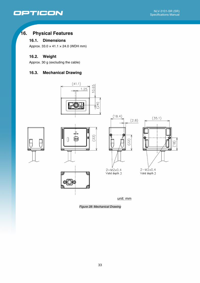
16. Physical Features 16.1. Dimensions Approx. 33.0 × 41.1 × 24.0 (WDH mm)
16.2. Weight Approx. 30 g (excluding the cable)
16.3. Mechanical Drawing
unit: mm
Figure 28: Mechanical Drawing
NLV-3101-SR (SR) Specifications Manual
34
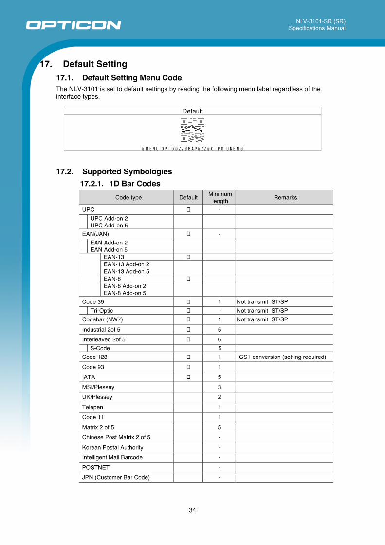
17. Default Setting 17.1. Default Setting Menu Code The NLV-3101 is set to default settings by reading the following menu label regardless of the interface types.
Default
@ M E N U_O P T O @ Z Z @ B A P @ Z Z @ O T P O_U N E M @
17.2. Supported Symbologies 17.2.1. 1D Bar Codes
Code type Default Minimum length Remarks
UPC � -
UPC Add-on 2 UPC Add-on 5
EAN(JAN) � -
EAN Add-on 2 EAN Add-on 5
EAN-13 � EAN-13 Add-on 2 EAN-13 Add-on 5
EAN-8 � EAN-8 Add-on 2 EAN-8 Add-on 5
Code 39 � 1 Not transmit ST/SP Tri-Optic � - Not transmit ST/SP Codabar (NW7) � 1 Not transmit ST/SP Industrial 2of 5 � 5 Interleaved 2of 5 � 6 S-Code 5 Code 128 � 1 GS1 conversion (setting required) Code 93 � 1 IATA � 5 MSI/Plessey 3 UK/Plessey 2 Telepen 1 Code 11 1 Matrix 2 of 5 5 Chinese Post Matrix 2 of 5 - Korean Postal Authority - Intelligent Mail Barcode - POSTNET - JPN (Customer Bar Code) -
NLV-3101-SR (SR) Specifications Manual
35
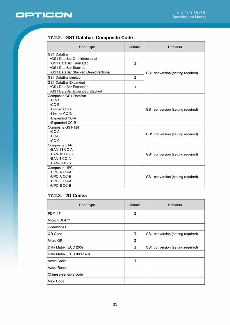
17.2.2. GS1 Databar, Composite Code
Code type Default Remarks
GS1 DataBar ・GS1 DataBar Omnidirectional ・GS1 DataBar Truncated ・GS1 DataBar Stacked ・GS1 DataBar Stacked Omnidirectional
�
GS1 conversion (setting required) GS1 DataBar Limited � GS1 DataBar Expanded ・GS1 DataBar Expanded ・GS1 DataBar Expanded Stacked
�
Composite GS1-DataBar ・CC-A ・CC-B ・Limited CC-A ・Limited CC-B ・Expanded CC-A ・Expanded CC-B
GS1 conversion (setting required)
Composite GS1-128 ・CC-A ・CC-B ・CC-C
GS1 conversion (setting required)
Composite EAN ・EAN-13 CC-A ・EAN-13 CC-B ・EAN-8 CC-A ・EAN-8 CC-B
GS1 conversion (setting required)
Composite UPC ・UPC-A CC-A ・UPC-A CC-B ・UPC-E CC-A ・UPC-E CC-B
GS1 conversion (setting required)
17.2.3. 2D Codes
Code type Default Remarks
PDF417 �
Micro PDF417
Codablock F
QR Code � GS1 conversion (setting required)
Micro QR �
Data Matrix (ECC 200) � GS1 conversion (setting required)
Data Matrix (ECC 000-140)
Aztec Code �
Aztec Runes
Chinese-sensible code
Maxi Code
NLV-3101-SR (SR) Specifications Manual
36
17.3. Other Default Item Default Setting
Read mode Single read Extended read time Disable Beeper duration 100 ms Beeper tone 2.7 kHz Startup beeper Enable Beeper loudness Max (100%) Beeper timing Before data transmission Good read LED indicator duration 200 ms Data buffering Buffered mode
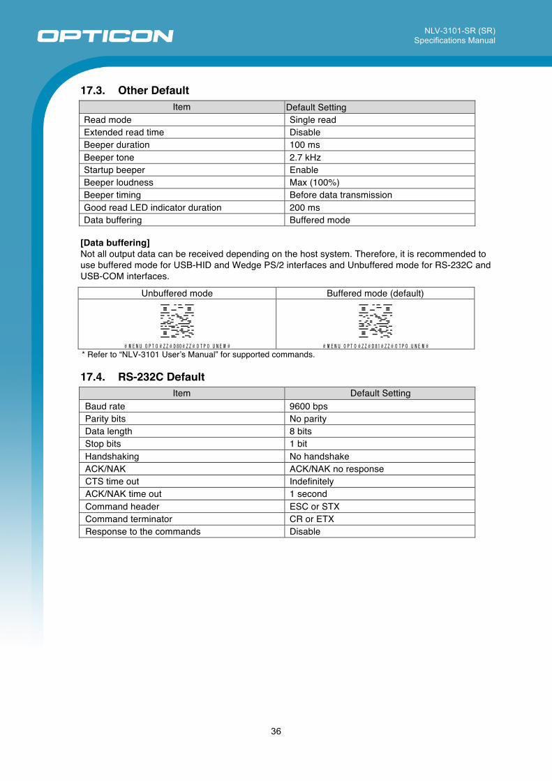
[Data buffering] Not all output data can be received depending on the host system. Therefore, it is recommended to use buffered mode for USB-HID and Wedge PS/2 interfaces and Unbuffered mode for RS-232C and USB-COM interfaces.
Unbuffered mode Buffered mode (default)
@ M E N U_ O P T O @ Z Z @ D 80 @ Z Z @ O T P O _U N E M @ @ M E N U_ O P T O @ Z Z @ D 81 @ Z Z @ O T P O _U N E M @ * Refer to “NLV-3101 Userʼs Manual” for supported commands.
17.4. RS-232C Default
Item Default Setting Baud rate 9600 bps Parity bits No parity Data length 8 bits Stop bits 1 bit Handshaking No handshake ACK/NAK ACK/NAK no response CTS time out Indefinitely ACK/NAK time out 1 second Command header ESC or STX Command terminator CR or ETX Response to the commands Disable
NLV-3101-SR (SR) Specifications Manual
37
17.5. USB-COM It is necessary to install OPTOELECTRONICS USB Driver to a host.
Item Description Baud rate USB2.0 Full Speed Power supply 500 mA Vender ID 065A Product ID A002
Supported OS Microsoft Windows 2000 / XP/ Vista / 7 (32/64 bit)
Standards CDC-ACM
17.6. USB-HID, Wedge Defaults
Item Default Setting Keyboard language USA Output mode Output all values Character encoding None “LF” output Disable
NLV-3101-SR (SR) Specifications Manual
38
18. Accessories 18.1. AC Adapter Specifications The NLV-3101 with RS-232C and Wedge PS/2 interfaces are shipped with a dedicated AC adapter “Universal AC Adapter Kit.” Plug connectors can be changed for each region. Refer to 18.2 for the detailed view.
Item Specifications Model Name SFP0602000P-PSE Order Part No. (USA) 32-00606-00 Dimensions 47.5 x 28.0 x 75.0 (WDH mm) DC Output Cable Length 1.8 M
Input Spec Voltage Range AC 90 ~ 265 V Supply Current 0.5 A max
Output Spec Voltage Range 5.7 ~ 6.3 V Maximum Current 2 A max
Operating Temperature 0 ~ 40°C
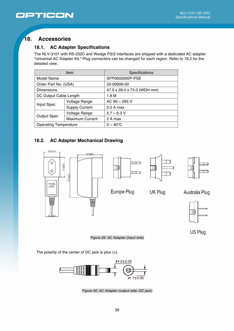
18.2. AC Adapter Mechanical Drawing
Figure 29: AC Adapter (input side)
The polarity of the center of DC jack is plus (+).
Figure 30: AC Adapter (output side: DC jack)