fjr13ad(c) - yamaha motorsports usa...yamaha continually seeks advancements in product design and...
TRANSCRIPT

DIC183
1MC-28199-10
FJR13AD(C)
OWNER’S MANUAL
Read this manual carefully before operating this vehicle.
LIT-11626-26-45

EAU10042
Read this manual carefully before operating this vehicle. This manual should stay with this vehicle if it is sold.
U1MC10E0.book Page 1 Monday, July 30, 2012 4:56 PM
INTRODUCTIONEAU10083
Congratulations on your purchase of the Yamaha FJR13AD(C). This model is the result of Yamaha’s vast experience in theproduction of fine sporting, touring, and pacesetting racing machines. It represents the high degree of craftsmanship andreliability that have made Yamaha a leader in these fields.This manual will give you an understanding of the operation, inspection, and basic maintenance of this motorcycle. If youhave any questions concerning the operation or maintenance of your motorcycle, please consult a Yamaha dealer.The design and manufacture of this Yamaha motorcycle fully comply with the emissions standards for clean air applicable atthe date of manufacture. Yamaha has met these standards without reducing the performance or economy of operation of themotorcycle. To maintain these high standards, it is important that you and your Yamaha dealer pay close attention to therecommended maintenance schedules and operating instructions contained within this manual.Yamaha continually seeks advancements in product design and quality. Therefore, while this manual contains the most cur-rent product information available at the time of printing, there may be minor discrepancies between your motorcycle and thismanual. If there is any question concerning this manual, please consult a Yamaha dealer.
WARNINGEWA10011
Please read this manual and the “YOU AND YOUR MOTORCYCLE: RIDING TIPS” booklet carefully before operatingthis motorcycle. Do not attempt to operate this motorcycle until you have attained adequate knowledge of its con-trols and operating features. Regular inspections and careful maintenance, along with good operating techniques,will help ensure that you safely enjoy the capabilities and reliability of this motorcycle.
U1MC10E0.book Page 1 Monday, July 30, 2012 4:56 PM

IMPORTANT MANUAL INFORMATIONEAU10133
Particularly important information is distinguished in this manual by the following notations:
*Product and specifications are subject to change without notice.
This is the safety alert symbol. It is used to alert you to potential personal injury hazards. Obey all safety messages that follow this symbol to avoid possible injury or death.
A WARNING indicates a hazardous situation which, if not avoided, could result in death or serious injury.
A NOTICE indicates special precautions that must be taken to avoid damage to the vehicle or other property.
A TIP provides key information to make procedures easier or clearer.
WARNING
NOTICE
TIP
U1MC10E0.book Page 1 Monday, July 30, 2012 4:56 PM

IMPORTANT MANUAL INFORMATION
EAU10193
FJR13AD(C)OWNER’S MANUAL
©2012 by Yamaha Motor Corporation, U.S.A.1st edition, July 2012All rights reserved.
Any reprinting or unauthorized use without the written permission of Yamaha Motor Corporation, U.S.A.
is expressly prohibited.Printed in Japan.
P/N LIT-11626-26-45
U1MC10E0.book Page 2 Monday, July 30, 2012 4:56 PM

TABLE OF CONTENTSLOCATION OF IMPORTANT LABELS .............................................1-1
SAFETY INFORMATION ..................2-1
DESCRIPTION ..................................3-1Left view ..........................................3-1Right view ........................................3-2Controls and instruments.................3-3
INSTRUMENT AND CONTROL FUNCTIONS .......................................4-1
Main switch/steering lock ................4-1Indicator lights and warning
lights ............................................4-2Cruise control system .....................4-4Multi-function meter unit .................4-8D-mode (drive mode) ....................4-20Handlebar switches ......................4-21Clutch lever ...................................4-23Shift pedal .....................................4-23Brake lever ...................................4-24Brake pedal ..................................4-24ABS ..............................................4-24Traction control system ................4-25Fuel tank cap ................................4-27Fuel ...............................................4-28Fuel tank breather/overflow
hose ..........................................4-29Catalytic converters ......................4-30Seats ............................................4-30
Adjusting the rider seat height ...... 4-32Storage compartments ................. 4-34Accessory box .............................. 4-35Adjusting the headlight beams ..... 4-35Handlebar position ....................... 4-36Opening and closing the cowling
vents ......................................... 4-36Rear view mirrors ......................... 4-37Adjusting the front fork ................. 4-38Adjusting the shock absorber
assembly ................................... 4-40Sidestand ..................................... 4-41Ignition circuit cut-off system ........ 4-42Auxiliary DC jack .......................... 4-44
FOR YOUR SAFETY – PRE-OPERATION CHECKS ............. 5-1
OPERATION AND IMPORTANT RIDING POINTS................................. 6-1
Starting the engine ......................... 6-1Shifting ........................................... 6-2Engine break-in .............................. 6-4Parking ........................................... 6-4
PERIODIC MAINTENANCE AND ADJUSTMENT ................................... 7-1
Owner’s tool kit ............................... 7-2Periodic maintenance chart for the
emission control system ............. 7-3
General maintenance and lubrication chart .......................... 7-5
Removing and installing panels ..... 7-9Checking the spark plugs ............ 7-12Canister (for California only) ........ 7-13Engine oil and oil filter cartridge ... 7-13Final gear oil ................................ 7-16Coolant ........................................ 7-17Cleaning the air filter element ...... 7-18Checking the engine idling
speed ........................................ 7-20Checking the throttle grip free
play ........................................... 7-20Valve clearance ........................... 7-20Tires ............................................. 7-21Cast wheels ................................. 7-23Clutch lever .................................. 7-24Checking the brake lever free
play ........................................... 7-24Brake light switches ..................... 7-25Checking the front and rear brake
pads .......................................... 7-25Checking the brake and clutch
fluid levels ................................. 7-26Changing the brake and clutch
fluids ......................................... 7-27Checking and lubricating the
cables ....................................... 7-27Checking and lubricating the
throttle grip and cable ............... 7-28
U1MC10E0.book Page 1 Monday, July 30, 2012 4:56 PM

TABLE OF CONTENTSChecking and lubricating the
brake and shift pedals ...............7-28Checking and lubricating the
brake and clutch levers .............7-29Checking and lubricating the
centerstand and sidestand ........7-29Lubricating the rear suspension ...7-30Lubricating the swingarm pivots ...7-30Checking the front fork .................7-31Checking the steering ...................7-31Checking the wheel bearings .......7-32Battery ..........................................7-32Replacing the fuses ......................7-33Headlight bulb ..............................7-35Front turn signal/position light ......7-35Replacing a rear turn signal light
bulb or a tail/brake light bulb .....7-36Replacing the license plate light
bulb ...........................................7-36Auxiliary light ................................7-37Troubleshooting ............................7-37Troubleshooting charts .................7-39
MOTORCYCLE CARE AND STORAGE ..........................................8-1
Matte color caution .........................8-1Care ................................................8-1Storage ...........................................8-4
SPECIFICATIONS ............................ 9-1
CONSUMER INFORMATION .......... 10-1Identification numbers .................. 10-1Reporting safety defects .............. 10-3Motorcycle noise regulation ......... 10-4Maintenance record ..................... 10-5YAMAHA MOTOR
CORPORATION, U.S.A. STREET AND ENDURO MOTORCYCLE LIMITED WARRANTY ............................. 10-7
YAMAHA EXTENDED SERVICE (Y.E.S.) ..................................... 10-9
U1MC10E0.book Page 2 Monday, July 30, 2012 4:56 PM
LOCATION OF IMPORTANT LABELS
1-1
1
EAU10384
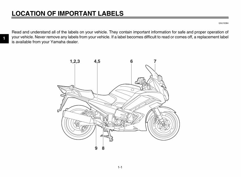
Read and understand all of the labels on your vehicle. They contain important information for safe and proper operation ofyour vehicle. Never remove any labels from your vehicle. If a label becomes difficult to read or comes off, a replacement labelis available from your Yamaha dealer.
89
61,2,3 4,5 7
U1MC10E0.book Page 1 Monday, July 30, 2012 4:56 PM
LOCATION OF IMPORTANT LABELS
1-2
1
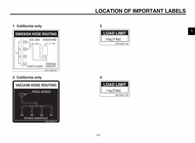
1 kg {2 lbs}4BR-24877-A0
LOAD LIMIT
3 kg {7 lbs}3TB-24877-A0
LOAD LIMIT
#4#3
#2#1
FUEL TANK
THROTTLE BODYCHARCOALCANISTER
ATMOSPHERE
EMISSION HOSE ROUTING
1MC-21686-00
VACUUM HOSE ROUTING
13S-21684-10
INTAKE MANIFOLD
PRESS. SENSOR
#1#2#3#4
1 California only 3
2 California only 4
U1MC10E0.book Page 2 Monday, July 30, 2012 4:56 PM

LOCATION OF IMPORTANT LABELS
1-3
1
250 kPa, {2.50 kgf/cm2}, 36 psi
290 kPa, {2.90 kgf/cm2}, 42 psi
250 kPa, {2.50 kgf/cm2}, 36 psi
290 kPa, {2.90 kgf/cm2}, 42 psi
5VY-21668-00NOTICECleaning with alkaline oracid cleaner, gasoline orsolvent will damagewindshield.Use neutral detergent.
4B5-2815K-00
5
7
6
8
9
U1MC10E0.book Page 3 Monday, July 30, 2012 4:56 PM

2-1
2
SAFETY INFORMATIONEAU1028A
Be a Responsible OwnerAs the vehicle’s owner, you are respon-sible for the safe and proper operationof your motorcycle.Motorcycles are single-track vehicles.Their safe use and operation are de-pendent upon the use of proper ridingtechniques as well as the expertise ofthe operator. Every operator shouldknow the following requirements beforeriding this motorcycle.He or she should:
● Obtain thorough instructions froma competent source on all aspectsof motorcycle operation.
● Observe the warnings and mainte-nance requirements in this Own-er’s Manual.
● Obtain qualified training in safeand proper riding techniques.
● Obtain professional technical ser-vice as indicated in this Owner’sManual and/or when made neces-sary by mechanical conditions.
● Never operate a motorcycle with-out proper training or instruction.Take a training course. Beginnersshould receive training from a cer-tified instructor. Contact an autho-rized motorcycle dealer to find outabout the training courses nearestyou.
Safe RidingPerform the pre-operation checks eachtime you use the vehicle to make sure itis in safe operating condition. Failure toinspect or maintain the vehicle properlyincreases the possibility of an accidentor equipment damage. See page 5-1for a list of pre-operation checks.
● This motorcycle is designed to car-ry the operator and a passenger.
● The failure of motorists to detectand recognize motorcycles in traf-fic is the predominating cause ofautomobile/motorcycle accidents.Many accidents have been causedby an automobile driver who didnot see the motorcycle. Making
yourself conspicuous appears tobe very effective in reducing thechance of this type of accident.Therefore:• Wear a brightly colored jacket.• Use extra caution when you are
approaching and passingthrough intersections, since in-tersections are the most likelyplaces for motorcycle accidentsto occur.
• Ride where other motorists cansee you. Avoid riding in anothermotorist’s blind spot.
• Never maintain a motorcyclewithout proper knowledge. Con-tact an authorized motorcycledealer to inform you on basicmotorcycle maintenance. Cer-tain maintenance can only becarried out by certified staff.
U1MC10E0.book Page 1 Monday, July 30, 2012 4:56 PM

SAFETY INFORMATION
2-2
2
● Many accidents involve inexperi-enced operators. In fact, many op-erators who have been involved inaccidents do not even have a cur-rent motorcycle license.• Make sure that you are qualified
and that you only lend your mo-torcycle to other qualified opera-tors.
• Know your skills and limits.Staying within your limits mayhelp you to avoid an accident.
• We recommend that you prac-tice riding your motorcyclewhere there is no traffic until youhave become thoroughly famil-iar with the motorcycle and all ofits controls.
● Many accidents have been causedby error of the motorcycle opera-tor. A typical error made by the op-erator is veering wide on a turndue to excessive speed or under-cornering (insufficient lean anglefor the speed).• Always obey the speed limit and
never travel faster than warrant-ed by road and traffic conditions.
• Always signal before turning orchanging lanes. Make sure thatother motorists can see you.
● The posture of the operator andpassenger is important for propercontrol.• The operator should keep both
hands on the handlebar andboth feet on the operator foot-rests during operation to main-tain control of the motorcycle.
• The passenger should alwayshold onto the operator, the seatstrap or grab bar, if equipped,with both hands and keep bothfeet on the passenger footrests.Never carry a passenger unlesshe or she can firmly place bothfeet on the passenger footrests.
● Never ride under the influence ofalcohol or other drugs.
● This motorcycle is designed for on-road use only. It is not suitable foroff-road use.
Protective ApparelThe majority of fatalities from motorcy-cle accidents are the result of head in-juries. The use of a safety helmet is thesingle most critical factor in the preven-tion or reduction of head injuries.
● Always wear an approved helmet.● Wear a face shield or goggles.
Wind in your unprotected eyescould contribute to an impairmentof vision that could delay seeing ahazard.
● The use of a jacket, heavy boots,trousers, gloves, etc., is effective inpreventing or reducing abrasionsor lacerations.
● Never wear loose-fitting clothes,otherwise they could catch on thecontrol levers, footrests, or wheelsand cause injury or an accident.
● Always wear protective clothingthat covers your legs, ankles, andfeet. The engine or exhaust sys-tem become very hot during or af-ter operation and can cause burns.
● A passenger should also observethe above precautions.
U1MC10E0.book Page 2 Monday, July 30, 2012 4:56 PM

SAFETY INFORMATION
2-3
2
Avoid Carbon Monoxide PoisoningAll engine exhaust contains carbonmonoxide, a deadly gas. Breathing car-bon monoxide can cause headaches,dizziness, drowsiness, nausea, confu-sion, and eventually death.Carbon Monoxide is a colorless, odor-less, tasteless gas which may bepresent even if you do not see or smellany engine exhaust. Deadly levels ofcarbon monoxide can collect rapidlyand you can quickly be overcome andunable to save yourself. Also, deadlylevels of carbon monoxide can lingerfor hours or days in enclosed or poorlyventilated areas. If you experience anysymptoms of carbon monoxide poison-ing, leave the area immediately, getfresh air, and SEEK MEDICAL TREAT-MENT.
● Do not run engine indoors. Even ifyou try to ventilate engine exhaustwith fans or open windows anddoors, carbon monoxide can rap-idly reach dangerous levels.
● Do not run engine in poorly venti-lated or partially enclosed areassuch as barns, garages, or car-ports.
● Do not run engine outdoors whereengine exhaust can be drawn intoa building through openings suchas windows and doors.
LoadingAdding accessories or cargo to yourmotorcycle can adversely affect stabili-ty and handling if the weight distributionof the motorcycle is changed. To avoidthe possibility of an accident, use ex-treme caution when adding cargo oraccessories to your motorcycle. Useextra care when riding a motorcyclethat has added cargo or accessories.Here, along with the information aboutaccessories below, are some generalguidelines to follow if loading cargo toyour motorcycle:The total weight of the operator, pas-senger, accessories and cargo mustnot exceed the maximum load limit.Operation of an overloaded vehiclecould cause an accident.
When loading within this weight limit,keep the following in mind:
● Cargo and accessory weightshould be kept as low and close tothe motorcycle as possible. Se-curely pack your heaviest items asclose to the center of the vehicle aspossible and make sure to distrib-ute the weight as evenly as possi-ble on both sides of the motorcycleto minimize imbalance or instabili-ty.
● Shifting weights can create a sud-den imbalance. Make sure that ac-cessories and cargo are securelyattached to the motorcycle beforeriding. Check accessory mountsand cargo restraints frequently.• Properly adjust the suspension
for your load (suspension-ad-justable models only), andcheck the condition and pres-sure of your tires.
• Never attach any large or heavyitems to the handlebar, frontfork, or front fender. Theseitems, including such cargo assleeping bags, duffel bags, or
Maximum load:FJR13AD 215 kg (474 lb)FJR13ADC 214 kg (472 lb)
U1MC10E0.book Page 3 Monday, July 30, 2012 4:56 PM
SAFETY INFORMATION
2-4
2
tents, can create unstable han-dling or a slow steering re-sponse.
● This vehicle is not designed topull a trailer or to be attached toa sidecar.
Genuine Yamaha AccessoriesChoosing accessories for your vehicleis an important decision. GenuineYamaha accessories, which are avail-able only from a Yamaha dealer, havebeen designed, tested, and approvedby Yamaha for use on your vehicle.Many companies with no connection toYamaha manufacture parts and acces-sories or offer other modifications forYamaha vehicles. Yamaha is not in aposition to test the products that theseaftermarket companies produce.Therefore, Yamaha can neither en-dorse nor recommend the use of ac-cessories not sold by Yamaha ormodifications not specifically recom-mended by Yamaha, even if sold andinstalled by a Yamaha dealer.
Aftermarket Parts, Accessories, andModificationsWhile you may find aftermarket prod-ucts similar in design and quality togenuine Yamaha accessories, recog-nize that some aftermarket accessoriesor modifications are not suitable be-cause of potential safety hazards to youor others. Installing aftermarket prod-ucts or having other modifications per-formed to your vehicle that change anyof the vehicle’s design or operationcharacteristics can put you and othersat greater risk of serious injury or death.You are responsible for injuries relatedto changes in the vehicle.Keep the following guidelines in mind,as well as those provided under “Load-ing” when mounting accessories.
● Never install accessories or carrycargo that would impair the perfor-mance of your motorcycle. Care-fully inspect the accessory beforeusing it to make sure that it doesnot in any way reduce groundclearance or cornering clearance,
limit suspension travel, steeringtravel or control operation, or ob-scure lights or reflectors.• Accessories fitted to the handle-
bar or the front fork area cancreate instability due to improperweight distribution or aerody-namic changes. If accessoriesare added to the handlebar orfront fork area, they must be aslightweight as possible andshould be kept to a minimum.
• Bulky or large accessories mayseriously affect the stability ofthe motorcycle due to aerody-namic effects. Wind may at-tempt to lift the motorcycle, orthe motorcycle may become un-stable in cross winds. These ac-cessories may also causeinstability when passing or beingpassed by large vehicles.
• Certain accessories can dis-place the operator from his orher normal riding position. Thisimproper position limits the free-dom of movement of the opera-
U1MC10E0.book Page 4 Monday, July 30, 2012 4:56 PM

SAFETY INFORMATION
2-5
2
tor and may limit control ability,therefore, such accessories arenot recommended.
● Use caution when adding electri-cal accessories. If electrical acces-sories exceed the capacity of themotorcycle’s electrical system, anelectric failure could result, whichcould cause a dangerous loss oflights or engine power.
Aftermarket Tires and RimsThe tires and rims that came with yourmotorcycle were designed to match theperformance capabilities and to providethe best combination of handling, brak-ing, and comfort. Other tires, rims, siz-es, and combinations may not beappropriate. Refer to page 7-21 for tirespecifications and more information onreplacing your tires.
Transporting the MotorcycleBe sure to observe following instruc-tions before transporting the motorcy-cle in another vehicle.
● Remove all loose items from themotorcycle.
● Check that the fuel cock (ifequipped) is in the “OFF” positionand that there are no fuel leaks.
● Point the front wheel straightahead on the trailer or in the truckbed, and choke it in a rail to pre-vent movement.
● Shift the transmission in gear (formodels with a manual transmis-sion).
● Secure the motorcycle with tie-downs or suitable straps that areattached to solid parts of the mo-torcycle, such as the frame or up-per front fork triple clamp (and not,for example, to rubber-mountedhandlebars or turn signals, or partsthat could break). Choose the lo-cation for the straps carefully sothe straps will not rub againstpainted surfaces during transport.
● The suspension should be com-pressed somewhat by the tie-downs, if possible, so that the mo-torcycle will not bounce excessive-ly during transport.
U1MC10E0.book Page 5 Monday, July 30, 2012 4:56 PM

DESCRIPTION
3-1
3
EAU10410
Left view
1 2 3 4
57 689101112131. Coolant reservoir (page 7-17)2. Accessory box (page 4-35)3. Front fork spring preload adjusting bolt (page 4-38)4. Owner’s tool kit (page 7-2)5. Final gear oil filler bolt (page 7-16)6. Final gear oil drain bolt (page 7-16)7. Shock absorber assembly spring preload adjusting lever (page 4-40)8. Air filter element (page 7-18)
9. Shift pedal (page 4-23)10.Engine oil filler cap (page 7-13)11.Engine oil filter cartridge (page 7-13)12.Engine oil level check window (page 7-13)13.Engine oil drain bolt (page 7-13)
U1MC10E0.book Page 1 Monday, July 30, 2012 4:56 PM

DESCRIPTION
3-2
3
EAU10420
Right view
891011
6,753,421
1. Storage compartment (page 4-34)2. Fuel tank cap (page 4-27)3. Front fork spring preload adjusting bolt (page 4-38)4. Front fork rebound damping force adjusting knob (page 4-38)5. Windshield (page 4-10)6. Fuses (page 7-33)7. Battery (page 7-32)8. Front fork compression damping force adjusting screw (page 4-38)
9. Brake pedal (page 4-24)10.Shock absorber assembly rebound damping force adjusting knob
(page 4-40)11.Rear brake fluid reservoir (page 7-26)
U1MC10E0.book Page 2 Monday, July 30, 2012 4:56 PM

DESCRIPTION
3-3
3
EAU10430
Controls and instruments
1 2 3 4 5 6 7 8 2 9
10,1112111. Clutch lever (page 4-23)2. Rear view mirror (page 4-37)3. Left handlebar switches (page 4-21)4. Clutch fluid reservoir (page 7-26)5. Multi-function meter unit (page 4-8)6. Main switch/steering lock (page 4-1)7. Front brake fluid reservoir (page 7-26)8. Right handlebar switches (page 4-21)
9. Brake lever (page 4-24)10.Throttle grip (page 7-20)11.Grip warmer (page 4-10)12.Headlight beam adjusting knob (page 4-35)
U1MC10E0.book Page 3 Monday, July 30, 2012 4:56 PM

INSTRUMENT AND CONTROL FUNCTIONS
4-1
4
EAU10461
Main switch/steering lock
The main switch/steering lock controlsthe ignition and lighting systems, and isused to lock the steering. The variouspositions are described below.
EAU51500
ONAll electrical circuits are supplied withpower; the meter lighting, taillights, li-cense plate light, auxiliary lights andposition lights come on, and the enginecan be started. The key cannot be re-moved.
TIPThe headlights come on automaticallywhen the engine is started and stay onuntil the key is turned to “OFF”.
EAU10661
OFFAll electrical systems are off. The keycan be removed.
WARNINGEWA10061
Never turn the key to “OFF” or“LOCK” while the vehicle is moving.Otherwise the electrical systems willbe switched off, which may result inloss of control or an accident.
EAU10692
LOCKThe steering is locked, and all electricalsystems are off. The key can be re-moved.
To lock the steering
1. Turn the handlebars all the way tothe left or right.
2. Push the key in from the “OFF” po-sition, and then turn it to “LOCK”while still pushing it.
3. Remove the key.
1. Push.2. Turn.
1 2
U1MC10E0.book Page 1 Monday, July 30, 2012 4:56 PM

INSTRUMENT AND CONTROL FUNCTIONS
4-2
4
To unlock the steering
Push the key into the main switch, andthen turn it to “OFF” while still pushingit.
EAU54740
(Parking)The steering is locked, and the tail-lights, license plate light, auxiliary lightsand position lights are on. The hazardlights and turn signal lights can beturned on, but all other electrical sys-tems are off. The key can be removed.The steering must be locked before thekey can be turned to “ ”.
NOTICEECA11020
Do not use the parking position foran extended length of time, other-wise the battery may discharge.
EAU49392
Indicator lights and warning lights
EAU11030
Turn signal indicator lights “ ” and “ ” The corresponding indicator light flash-es when the turn signal switch ispushed to the left or right.
1. Push.2. Turn.
1 2
1. Left turn signal indicator light “ ”2. Engine trouble warning light “ ”3. Oil level warning light “ ”4. Neutral indicator light “ ”5. High beam indicator light “ ”6. Anti-lock Brake System (ABS) warning
light “ ”7. Right turn signal indicator light “ ”8. Traction control system indicator/warning
light “TCS”9. Cruise control indicator lights
GEAR
N77
A.TEMP ˚F
LoC.TEMP ˚F
0:06TIME TRIP
1 72 63
89
54
ABS
U1MC10E0.book Page 2 Monday, July 30, 2012 4:56 PM

INSTRUMENT AND CONTROL FUNCTIONS
4-3
4
EAU11060
Neutral indicator light “ ” This indicator light comes on when thetransmission is in the neutral position.
EAU11080
High beam indicator light “ ” This indicator light comes on when thehigh beam of the headlight is switchedon.
EAU11123
Oil level warning light “ ” This warning light comes on if the en-gine oil level is low.The electrical circuit of the warning lightcan be checked by turning the key to“ON”. The warning light should comeon for a few seconds, and then go off.If the warning light does not come oninitially when the key is turned to “ON”,or if the warning light remains on, havea Yamaha dealer check the electricalcircuit.
TIPEven if the oil level is sufficient, thewarning light may flicker when riding ona slope or during sudden accelerationor deceleration, but this is not a mal-function.
EAU11380
Cruise control indicator lights See page 4-4 for an explanation ofthese indicator lights.
EAU11534
Engine trouble warning light “ ” This warning light comes on or flashesif a problem is detected in the electricalcircuit monitoring the engine. If this oc-curs, have a Yamaha dealer check theself-diagnosis system. (See page 4-20for an explanation of the self-diagnosisdevice.)The electrical circuit of the warning lightcan be checked by turning the key to“ON”. The warning light should comeon for a few seconds, and then go off.
If the warning light does not come oninitially when the key is turned to “ON”,or if the warning light remains on, havea Yamaha dealer check the electricalcircuit.
EAU51661
ABS warning light “ ” In normal operation, the ABS warninglight comes on when the key is turnedto “ON”, and goes off after traveling at aspeed of 10 km/h (6 mi/h) or higher.If the ABS warning light:
● does not come on when the key isturned to “ON”
● comes on or flashes while riding● does not go off after traveling at a
speed of 10 km/h (6 mi/h) or higherThe ABS may not work correctly. If anyof the above occurs, have a Yamahadealer check the system as soon aspossible. (See page 4-24 for an expla-nation of the ABS.)
WARNINGEWA16040
If the ABS warning light does not gooff after traveling at a speed of 10km/h (6 mi/h) or higher, or if thewarning light comes on or flashes
ABS
U1MC10E0.book Page 3 Monday, July 30, 2012 4:56 PM

INSTRUMENT AND CONTROL FUNCTIONS
4-4
4
while riding, the brake system re-verts to conventional braking. If ei-ther of the above occurs, or if thewarning light does not come on atall, use extra caution to avoid possi-ble wheel lock during emergencybraking. Have a Yamaha dealercheck the brake system and electri-cal circuits as soon as possible.
TIPIf the start switch is pushed while theengine is running, the ABS warninglight will come on, but this is not a mal-function.
EAU54260
Traction control system indica-tor/warning light “TCS” This indicator/warning light flasheswhen the traction control system en-gages and comes on when the systemis turned off.The electrical circuit of the light can bechecked by turning the key to “ON”.The light should come on for a few sec-onds, and then go off.
If the light does not come on initiallywhen the key is turned to “ON”, or if thelight remains on, have a Yamaha deal-er check the electrical circuit.If the traction control system becomesdisabled while riding, the indica-tor/warning light and engine troublewarning light come on. (See page 4-25for an explanation of the traction controlsystem.)
Try to reset the traction control systemand the lights by following the proce-dures under “Resetting” on page 4-26.
EAU54760
Cruise control system This model is equipped with a cruisecontrol system designed to maintain aset cruising speed.The cruise control system operatesonly when riding in 3rd, 4th or 5th gearat speeds between about 50 km/h (31mi/h) and 128 km/h (80 mi/h).
WARNINGEWA16340
● Improper use of the cruise con-trol system may result in loss ofcontrol, which could lead to anaccident. Do not activate thecruise control system in heavytraffic, poor weather conditions,or among winding, slippery,hilly, rough or gravel roads.
● When traveling uphill or down-hill, the cruise control systemmay not be able to maintain theset cruising speed.
● To prevent accidentally activat-ing the cruise control system,turn it off when not in use. Makesure that the cruise control sys-tem indicator light “ ” is off.
1. Engine trouble warning light “ ”2. Traction control system indicator/warning
light “TCS”
NA.TEMP
C.TEMP
TIME TR
21
U1MC10E0.book Page 4 Monday, July 30, 2012 4:56 PM

INSTRUMENT AND CONTROL FUNCTIONS
4-5
4
Activating and setting the cruisecontrol system
1. Push the cruise control powerswitch “ ” located on the left han-dlebar. The cruise control systemindicator light “ ” will come on.
2. Push the “SET–” side of the cruisecontrol setting switch to activatethe cruise control system. Yourcurrent traveling speed will be-come the set cruising speed. Thecruise control setting indicator light“SET” will come on.
Adjusting the set cruising speedWhile the cruise control system is oper-ating, push the “RES+” side of thecruise control setting switch to increasethe set cruising speed or the “SET–”side to decrease the set speed.
TIPPushing the setting switch once willchange the speed in increments of ap-proximately 2.0 km/h (1.2 mi/h). Hold-ing the “RES+” or “SET–” side of thecruise control setting switch down willincrease or decrease the speed contin-uously until the switch is released.
You can also manually increase yourtraveling speed using the throttle. Afteryou have accelerated, you can set anew cruising speed by pushing the“SET–” side of the setting switch. If youdo not set a new cruising speed, whenyou return the throttle grip, the vehiclewill decelerate to the previously setcruising speed.
Deactivating the cruise control sys-temPerform one of the following operationsto cancel the set cruising speed. The“SET” indicator light will go off.
● Turn the throttle grip past theclosed position in the decelerationdirection.
1. Cruise control system indicator light “ ”2. Cruise control setting indicator light “SET”
1. Cruise control setting switch “RES+/SET–”2. Cruise control power switch “ ”
NA.TEMP
C.TEMP
TIME TR
21
RES
SET
PASS
1
2
U1MC10E0.book Page 5 Monday, July 30, 2012 4:56 PM

INSTRUMENT AND CONTROL FUNCTIONS
4-6
4
● Apply the front or rear brake.● Disengage the clutch.
Push the power switch to turn off thecruise control system. The “ ” indica-tor light and the “SET” indicator light willgo off.
TIPTraveling speed decreases as soon asthe cruise control system is deactivat-ed; unless the throttle grip is turned.
Using the resume functionPush the “RES+” side of the cruise con-trol setting switch to reactivate thecruise control system. The traveling
speed will return to the previously setcruising speed. The “SET” indicatorlight will come on.
WARNINGEWA16350
It is dangerous to use the resumefunction when the previously setcruising speed is too high for cur-rent conditions.
TIP● The resume function operates
when riding in 3rd, 4th or 5th gearat speeds between about 50 km/h(31 mi/h) and 128 km/h (80 mi/h).
● Pushing the power switch whilethe system is operating will turnthe system off completely anderase the previously set cruisingspeed. You will not be able to usethe resume function until a newcruising speed has been set.
Automatic deactivation of the cruisecontrol systemThe cruise control system for this mod-el is electronically controlled and islinked with the other control systems.
The cruise control system will automat-ically become deactivated under thefollowing conditions:
● The cruise control system is notable to maintain the set cruisingspeed.
● Wheel slip or wheel spin is detect-ed. (If the traction control systemhas not been turned off, the trac-tion control system will work.)
● The start/engine stop switch is setto the “ ” position.
● The engine stalls.● The sidestand is lowered.
When traveling with a set cruisingspeed, if the cruise control system isdeactivated under the above condi-tions, the “ ” indicator light will go offand the “SET” indicator light will flashfor 4 seconds, and then go off.When not traveling with a set cruisingspeed, if the start/engine stop switch isset to the “ ” position, the enginestalls, or the sidestand is lowered, thenthe “ ” indicator light will go off (the“SET” indicator light will not flash).
1. Closed position2. Cruise control cancel direction
2 1
U1MC10E0.book Page 6 Monday, July 30, 2012 4:56 PM
INSTRUMENT AND CONTROL FUNCTIONS
4-7
4
If the cruise control system is automati-cally deactivated, please stop and con-firm that your vehicle is in goodoperating condition.Before using the cruise control systemagain, activate it using the powerswitch.
TIPIn some cases, the cruise control sys-tem may not be able to maintain the setcruising speed when the vehicle is trav-eling uphill or downhill.
● When the vehicle is traveling up-hill, the actual traveling speed maybecome lower than the set cruisingspeed. If this occurs, accelerate tothe desired traveling speed usingthe throttle.
● When the vehicle is travelingdownhill, the actual travelingspeed may become higher thanthe set cruising speed. If this oc-curs, the setting switch cannot beused to adjust the set cruisingspeed. To reduce the travelingspeed, apply the brakes. When the
brakes are applied, the cruise con-trol system will become deactivat-ed.
Self-diagnosis device
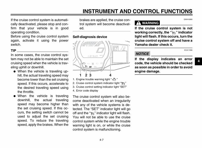
The cruise control system will also be-come deactivated when an irregularitywith any of the vehicle systems is de-tected. The “SET” indicator light will gooff and the “ ” indicator light will flash.You will not be able to use the cruisecontrol system while the engine troublewarning light is on, or while the cruisecontrol system is malfunctioning.
WARNINGEWA16360
If the cruise control system is notworking correctly, the “ ” indicatorlight will flash. If this occurs, turn thecruise control system off and have aYamaha dealer check it.
NOTICEECA11590
If the display indicates an errorcode, the vehicle should be checkedas soon as possible in order to avoidengine damage.
1. Engine trouble warning light “ ”2. Cruise control system indicator light “ ”3. Cruise control setting indicator light “SET”4. Error code display
GEAR
N25
A.TEMP ˚C
LoC.TEMP ˚C
0:06TIME TRIP
1 2 3 4
U1MC10E0.book Page 7 Monday, July 30, 2012 4:56 PM

INSTRUMENT AND CONTROL FUNCTIONS
4-8
4
EAU54781
Multi-function meter unit
WARNINGEWA12422
Be sure to stop the vehicle beforemaking any setting changes to themulti-function meter unit. Changing
settings while riding can distract theoperator and increase the risk of anaccident.
TIPThe select switch “ / ” and themenu switch “MENU” are located onthe left handlebar. These switches al-low you to control or change the set-tings of the multi-function meter unit.
The multi-function meter unit isequipped with the following:
● a speedometer● a tachometer● a clock● a fuel meter● a transmission gear display
● a drive mode display (which showsthe selected drive mode)
● a function display (which showsthe selected function)
● an information display (whichshows various information, suchas the odometer reading)
● a setting mode display (which al-lows you to set, select, or reset theitems shown in the information dis-play)
● a self-diagnosis device
TIP● Be sure to turn the key to “ON” be-
fore pushing the selectswitch “ / ”, menu switch“MENU”, “RESET” button and“TCS” button.
● To switch the meter displays be-tween kilometers and miles, seepage 4-14.
1. “RESET” button2. “TCS” button3. Tachometer4. Clock5. Fuel meter6. Eco indicator “ECO”7. Drive mode display8. Speedometer9. Transmission gear display10.Function display11.Information display
GEAR
N77
A.TEMP ˚F
LoC.TEMP ˚F
0:06TIME TRIP
12 3 114 5 876 9 10
1. Menu switch “MENU”2. Select switch “ / ”
1
2
U1MC10E0.book Page 8 Monday, July 30, 2012 4:56 PM

INSTRUMENT AND CONTROL FUNCTIONS
4-9
4
Tachometer
The electric tachometer allows the riderto monitor the engine speed and keep itwithin the ideal power range.When the key is turned to “ON”, the ta-chometer needle sweeps once acrossthe r/min range and then returns to zeror/min in order to test the electrical cir-cuit.
NOTICEECA10031
Do not operate the engine in the ta-chometer red zone.Red zone: 9000 r/min and above
Fuel meter
The fuel meter indicates the amount offuel in the fuel tank. The display seg-ments of the fuel meter disappear to-wards “E” (Empty) as the fuel leveldecreases. When the last segmentstarts flashing, refuel as soon as possi-ble.When the key is turned to “ON”, all dis-play segments come on once in orderto test the electrical circuit.
TIPThis fuel meter is equipped with a self-diagnosis system. If a problem is de-tected in the electrical circuit, all display
segments start flashing. If this occurs,have a Yamaha dealer check the elec-trical circuit.
Eco indicator
This indicator comes on when the vehi-cle is being operated in an environmen-tally friendly, fuel-efficient manner. Theindicator goes off when the vehicle isstopped.
TIPConsider the following tips to reducefuel consumption:
● Avoid high engine speeds duringacceleration.
● Travel at a constant speed.
1. Tachometer2. Tachometer red zone
1 2
1. Fuel meter
GEAR
NA.TEMP
C.TEMP
1
1. Eco indicator “ECO”
GEAR
NA.TEMP
C.TEMP
1
U1MC10E0.book Page 9 Monday, July 30, 2012 4:56 PM

INSTRUMENT AND CONTROL FUNCTIONS
4-10
4
● Select the transmission gear thatis appropriate for the vehiclespeed.
Transmission gear display
This display shows the selected gear.The neutral position is indicated by “ ”and by the neutral indicator light “ ”.
Drive mode display
This display indicates which drivemode has been selected: Touringmode “T” or sports mode “S”. For moredetails on the modes and on how to se-lect them, see pages 4-20 and 4-22.
Function display
Push the menu switch “MENU” toswitch the display between the wind-shield adjusting function, grip warmeradjusting function, and information dis-play selection function.
Adjusting the windshield positionTo move the windshield up, pushthe “ ” side of the select switch. Tomove the windshield down, pushthe “ ” side of the select switch.
1. Neutral indicator light “ ”2. Transmission gear display
GEAR
N77
A.TEMP ˚F
LoC.TEMP ˚F
0:06TIME TRIP
1 2
1. Drive mode display
GEAR
NA.TEMP
C.TEMP
1
1. Function display2. Windshield adjusting function3. Grip warmer adjusting function4. Information display selection function
GEAR
N77
A.TEMP ˚F
LoC.TEMP ˚F
0:06TIME TRIP
1 2
34
U1MC10E0.book Page 10 Monday, July 30, 2012 4:56 PM

INSTRUMENT AND CONTROL FUNCTIONS
4-11
4
Adjusting the grip warmerThis vehicle is equipped with gripwarmers, which can only be used whenthe engine is running. There are 4 gripwarmer settings.
To increase the grip warmer tempera-ture, push the “ ” side of the selectswitch. To decrease the grip warmertemperature, push the “ ” side of theselect switch.
NOTICEECA17930
● Be sure to wear gloves when us-ing the grip warmers.
● If the ambient temperature is 20°C (68 °F) or higher, do not setthe grip warmer to the high set-ting.
● If the handlebar grip or throttlegrip becomes worn or damaged,stop using the grip warmers andreplace the grips.
Selecting the information display
There are 3 information displays. Theselected information display can beswitched by pushing the select switch.The following items are shown in the in-formation displays:
● an odometer display● tripmeter displays● a fuel reserve tripmeter display
● an estimated traveling range dis-play
● an elapsed time display● an ambient temperature display● a coolant temperature display● an average fuel consumption dis-
play● an instantaneous fuel consump-
tion displayThe items shown in each informationdisplay can be selected.To set or select the items shown, seepage 4-14.
Odometer display:
Tripmeter displays:
Off
Low
Middle
DisplaySetting
High
1. Information display2. Display–13. Display–24. Display–3
GEAR
N3.1
TRIP-1 mile
4.3TRIP-2 mile
mile
12ODO
GEAR
N7
RANGE mile
7.6FUEL AVG MPG
MPG
7.6FUEL CRNT
GEAR
N77
A.TEMP ˚F
LoC.TEMP ˚F
0:06TIME TRIP
3
421
12ODO mile
3.1TRIP-1 mile
4.3TRIP-2 mile
U1MC10E0.book Page 11 Monday, July 30, 2012 4:56 PM

INSTRUMENT AND CONTROL FUNCTIONS
4-12
4
“TRIP-1” and “TRIP-2” show the dis-tance traveled since they were last setto zero.
When approximately 5.5 L (1.45 USgal, 1.21 Imp.gal) of fuel remains in thefuel tank, the last segment of the fuelmeter starts flashing. In addition, the in-formation display will automaticallychange to the fuel reserve tripmetermode “TRIP-F” and start counting thedistance traveled from that point.
In that case, pushing the select switchswitches the display between the vari-ous information displays in the follow-ing order;
TRIP-F → Display–1 → Display–2 →Display–3 → TRIP-F
To reset a tripmeter, use the selectswitch to select the information displaythat contains the tripmeter. Push the“RESET” button briefly so that the trip-meter flashes, and then push the “RE-SET” button again for at least 2seconds while the tripmeter is flashing.If you do not reset the fuel reserve trip-meter manually, it will reset itself auto-matically and the display will return tothe prior mode after refueling and trav-eling 5 km (3 mi).
Estimated traveling range display:
The distance that can be traveled withthe remaining fuel in the fuel tank underthe current riding conditions is shown.
Elapsed time display:
The time that has elapsed since the keywas turned to “ON” is shown. The max-imum time that can be shown is 99:59.This display is automatically reset whenthe key is turned to “OFF”.
TIPThere are also “TIME–2” and “TIME–3”elapsed time displays, but they cannotbe set to the information display. See“Setting mode” on page 4-14 for de-tailed information.
Ambient temperature display:
This display shows the ambient tem-perature from 16 °F to 122 °F in 1 °F in-crements. The temperature displayedmay vary from the ambient tempera-ture.
GEAR
4
2.1TRIP-F mile 7
RANGE mile
0:06TIME TRIP
77A.TEMP ˚F
U1MC10E0.book Page 12 Monday, July 30, 2012 4:56 PM

INSTRUMENT AND CONTROL FUNCTIONS
4-13
4
TIP● 16 °F will be displayed even if the
ambient temperature falls below16 °F.
● 122 °F will be displayed even if theambient temperature climbs above122 °F.
● The accuracy of the temperaturereading may be affected whenriding slowly [approximately under20 km/h (12.5 mi/h)] or whenstopped at traffic signals, railroadcrossings, etc.
Coolant temperature display:
The coolant temperature display indi-cates the temperature of the coolant.The coolant temperature varies withchanges in the weather and engineload.If the message “Hi” flashes, stop the ve-hicle, then stop the engine, and let theengine cool. (See page 7-40.)
TIPThe selected information display can-not be switched while the message “Hi”is flashing.
NOTICEECA10021
Do not continue to operate the en-gine if it is overheating.
Average fuel consumption display:
The average fuel consumption displaymodes “km/L”, “L/100km” or “MPG”show the average fuel consumptionsince the display was last reset.
● The “km/L” display shows the av-erage distance that can be trav-eled on 1.0 L of fuel.
● The “L/100km” display shows theaverage amount of fuel necessaryto travel 100 km.
● The “MPG” display shows the av-erage distance that can be trav-eled on 1.0 US gal of fuel.
To reset the average fuel consumptiondisplay, use the select switch to selectthe information display that containsthe average fuel consumption display.Push the “RESET” button briefly so thatthe average fuel consumption displayflashes, and then push the “RESET”button again for at least 2 secondswhile the display is flashing.
TIPAfter resetting the average fuel con-sumption display, “_ _._” will be shownfor that display until the vehicle hastraveled 1 km (0.6 mi).
LoC.TEMP ˚F
GEAR
4
HiC.TEMP ˚F
7.6FUEL AVG MPG
U1MC10E0.book Page 13 Monday, July 30, 2012 4:56 PM

INSTRUMENT AND CONTROL FUNCTIONS
4-14
4
NOTICEECA15473
If there is a malfunction, “– –.–” willbe continuously displayed. Have aYamaha dealer check the vehicle.
Instantaneous fuel consumption dis-play:
The instantaneous fuel consumptiondisplay modes “km/L”, “L/100km” or“MPG” show the fuel consumption un-der the current riding conditions.
● The “km/L” display shows the dis-tance that can be traveled on 1.0 Lof fuel.
● The “L/100km” display shows theamount of fuel necessary to travel100 km.
● The “MPG” display shows the dis-tance that can be traveled on 1.0US gal of fuel.
TIPIf traveling at speeds under 10 km/h(6.2 mi/h), “_ _._” will be displayed.
NOTICEECA15473
If there is a malfunction, “– –.–” willbe continuously displayed. Have aYamaha dealer check the vehicle.
Setting mode
TIP● The transmission must be in neu-
tral and the vehicle must bestopped to change settings in thismode.
● Shifting the transmission into gearand starting off, or turning the keyto “OFF”, saves all settings made,then exits the setting mode.
Push and hold the menu switch“MENU” for at least 2 seconds to enterthe setting mode. To exit the settingmode and return to the normal display,push and hold the menu switch“MENU” again for at least 2 seconds.
7.6FUEL CRNT MPG
1. Setting mode display
MENU
Grip WarmerMaintenanceTime TripUnitDisplayBrightnessClock
1
Display Description
“Grip Warmer”
This function allows you to set the low, middle, and high settings to 10 temper-ature levels.
“Maintenance”
This function allows you to set the oil change interval (distance traveled) and 2 other maintenance inter-vals. This function can also be reset.
“Time Trip”
This function allows you to check and reset the “TIME–2” and “TIME–3” functions. These time trips show the total elapsed time that the key has been in the “ON” position. When the key is turned to “OFF”, the trip times stop counting but are not reset. The max-imum time that can be shown is 99:59.
U1MC10E0.book Page 14 Monday, July 30, 2012 4:56 PM

INSTRUMENT AND CONTROL FUNCTIONS
4-15
4
Adjusting the temperature levels of thegrip warmer settings
1. Use the select switch to highlight“Grip Warmer”.
2. Push the menu switch “MENU”.The grip warmer setting displaywill be shown and “High” will flashin the display.
3. Push the menu switch “MENU”.The temperature level for the highsetting will start flashing.
Use the select switch to set thetemperature level, and then pushthe menu switch “MENU”. “High”will start flashing.
4. Use the select switch to highlight“Middle” or “Low”, and thenchange the setting using the sameprocedure that was used for thehigh setting.
5. When you are finished changingthe settings, use the select switchto highlight “ ”, and then push themenu switch “MENU” to return tothe setting mode menu.
“Unit”
This function allows you to switch the display units be-tween kilometers and miles. When kilometers are selected, the fuel con-sumption units can be switched between “L/100km” and “km/L”.
“Display”This function allows you to change the items shown in 3 information displays.
“Brightness”
This function allows you to adjust the brightness of the multi-function meter unit panel to suit the outside lighting conditions.
“Clock” This function allows you to set the clock.
“All Reset”This function allows you to reset all items, except the odometer and the clock.
MENU
Grip WarmerMaintenanceTime TripUnitDisplayBrightnessClock
Grip Warmer
High10
Middle5
Low1
Grip Warmer
High10
Middle5
Low1
U1MC10E0.book Page 15 Monday, July 30, 2012 4:56 PM

INSTRUMENT AND CONTROL FUNCTIONS
4-16
4 TIPThe setting can be set to 10 tempera-ture levels.
Resetting the maintenance counters1. Use the select switch to highlight
“Maintenance”.
2. Push the menu switch “MENU”,and then push the “RESET” buttonto select the item to reset.
3. While the selected item is flashing,push the “RESET” button for atleast 2 seconds.
4. Push the menu switch “MENU” toreturn to the setting mode menu.
Checking and resetting “TIME–2” and“TIME–3”
1. Use the select switch to highlight“Time Trip”.
2. Push the menu switch “MENU” todisplay “TIME–2” and “TIME–3”.To reset a time trip, push the “RE-SET” button to select the item toreset.
3. While the selected item is flashing,push the “RESET” button for atleast 2 seconds.
Grip Warmer
High10
Middle5
Low1
MENU
Grip WarmerMaintenanceTime TripUnitDisplayBrightnessClock
12OIL mile
6FREE-1 mile
6FREE-2 mile
Maintenance
MENU
Grip WarmerMaintenanceTime TripUnitDisplayBrightnessClock
TIME-2 0:07TIME-3 0:07
Time Trip
U1MC10E0.book Page 16 Monday, July 30, 2012 4:56 PM

INSTRUMENT AND CONTROL FUNCTIONS
4-17
4
4. Push the menu switch “MENU” toreturn to the setting mode menu.
Selecting the units1. Use the select switch to highlight
“Unit”.
2. Push the menu switch “MENU”.The unit setting display will beshown and “km or mile” will flash inthe display.
3. Push the menu switch “MENU”.“km” or “mile” will flash in the dis-play.
4. Use the select switch to select“km” or “mile”, and then push themenu switch “MENU”.
TIPWhen “km” is selected, “L/100km” or“km/L” can be set as the fuel consump-tion units. To set the fuel consumptionunits, proceed as follows. If “mile” wasselected, skip steps 5 and 6.
5. Use the select switch to select“km/L or L/100km”.
6. Push the menu switch “MENU”,use the select switch to select“L/100km” or “km/L”, and thenpush the menu switch “MENU”again.
7. Use the select switch tohighlight “ ”, and then push themenu switch “MENU” to return tothe setting mode menu.
Selecting the display items1. Use the select switch to highlight
“Display”.
MENU
Grip WarmerMaintenanceTime TripUnitDisplayBrightnessClock
Unit
km or milemile
Unit
km or milekm
km/L or L/100kmkm/L
Unit
km or milekm
km/L or L/100kmkm/L
U1MC10E0.book Page 17 Monday, July 30, 2012 4:56 PM

INSTRUMENT AND CONTROL FUNCTIONS
4-18
4 2. Push the menu switch “MENU”,use the select switch to highlightthe display to change, and thenpush the menu switch “MENU”again.
3. Use the select switch to highlightthe item to change, and then pushthe menu switch “MENU”.
4. Use the select switch to select theitem to show, and then push themenu switch “MENU”.
5. When you are finished changingthe settings, use the select switchto highlight “ ”, and then push themenu switch “MENU” to return tothe previous display.
6. Use the select switch tohighlight “ ”, and then push themenu switch “MENU” to return tothe setting mode menu.
Adjusting the meter panel brightness1. Use the select switch to highlight
“Brightness”.
2. Push the menu switch “MENU”.
MENU
Grip WarmerMaintenanceTime TripUnitDisplayBrightnessClock
Display
Display-1Display-2
Display-3
Display-1
1-1A.TEMP
1-2C.TEMP
1-3TIME TRIP
Display-1
1-1ODO
1-2C.TEMP
1-3TIME TRIP
Display-1
1-1ODO
1-2C.TEMP
1-3TIME TRIP
MENU
Grip WarmerMaintenanceTime TripUnitDisplayBrightnessClock
U1MC10E0.book Page 18 Monday, July 30, 2012 4:56 PM

INSTRUMENT AND CONTROL FUNCTIONS
4-19
4
3. Use the select switch to select thedesired brightness level, and thenpush the menu switch “MENU” toreturn to the setting mode menu.
Setting the clock1. Use the select switch to highlight
“Clock”.
2. Push the menu switch “MENU”.
3. When the hour digits start flashing,use the select switch to set thehours.
4. Push the menu switch “MENU”,and the minute digits start flashing.
5. Use the select switch to set theminutes.
6. Push the menu switch “MENU” toreturn to the setting mode menu.
Resetting all of the display items1. Use the select switch to highlight
“All Reset”.
2. Push the menu switch “MENU”.3. Use the select switch to highlight
“YES”, and then push the menuswitch “MENU”.
TIPThe odometer and the clock cannot bereset.
Brightness
MENU
Grip WarmerMaintenanceTime TripUnitDisplayBrightnessClock
Clock
5 55
MENU
MaintenanceTime TripUnitDisplayBrightnessClockAll Reset
All Reset
YES
NO
U1MC10E0.book Page 19 Monday, July 30, 2012 4:56 PM

INSTRUMENT AND CONTROL FUNCTIONS
4-20
4
Self-diagnosis device
This model is equipped with a self-diag-nosis device for various electrical cir-cuits. If a problem is detected in any ofthose circuits, the engine trouble warn-ing light will come on and the informa-tion display will indicate an error code.If the information display indicates anyerror codes, note the code number, andthen have a Yamaha dealer check thevehicle.
NOTICEECA11590
If the display indicates an errorcode, the vehicle should be checkedas soon as possible in order to avoidengine damage.
EAU49431
D-mode (drive mode) D-mode is an electronically controlledengine performance system with twomode selections (touring mode “T” andsports mode “S”).Push the drive mode switch “MODE” toswitch between modes. (See page4-22 for an explanation of the drivemode switch.)
TIPBefore using D-mode, make sure youunderstand its operation along with theoperation of the drive mode switch.
Touring mode “T”The touring mode “T” is suitable for var-ious riding conditions.
1. Engine trouble warning light “ ”2. Error code display
GEAR
N25
A.TEMP ˚C
LoC.TEMP ˚C
0:06TIME TRIP
1 2
1. Drive mode switch “MODE”
STOP
MODE
RUNSTART
1
U1MC10E0.book Page 20 Monday, July 30, 2012 4:56 PM

INSTRUMENT AND CONTROL FUNCTIONS
4-21
4
This mode allows the rider to enjoysmooth drivability from the low-speedrange to the high-speed range.
Sports mode “S”This mode offers a sportier engine re-sponse in the low- to mid-speed rangecompared to the touring mode.
EAU1234B
Handlebar switches
Left
Right
EAU54200
Dimmer/Pass switch “ / /PASS” Set this switch to “ ” for the highbeam and to “ ” for the low beam.To flash the high beam, push the passside “PASS” of the switch while theheadlights are on low beam.
EAU12460
Turn signal switch “ / ” To signal a right-hand turn, push thisswitch to “ ”. To signal a left-handturn, push this switch to “ ”. When re-leased, the switch returns to the center
1. Menu switch “MENU”2. Select switch “ / ”3. Cruise control switches4. Horn switch “ ”5. Turn signal switch “ / ”6. Dimmer/Pass switch “ / /PASS”
RES
SET
PASS
1
6
5
4
2
3
1. Start/Engine stop switch “ / / ”2. Drive mode switch “MODE”3. Hazard switch “ ”
STOP
MODE
RUNSTART
3
2
1
U1MC10E0.book Page 21 Monday, July 30, 2012 4:56 PM

INSTRUMENT AND CONTROL FUNCTIONS
4-22
4
position. To cancel the turn signallights, push the switch in after it has re-turned to the center position.
EAU12500
Horn switch “ ” Press this switch to sound the horn.
EAU54210
Start/Engine stop switch “ / / ” To crank the engine with the starter, setthis switch to “ ”, and then pushthe “ ” side of the switch. See page6-1 for starting instructions prior tostarting the engine.Set this switch to “ ” to stop the en-gine in case of an emergency, such aswhen the vehicle overturns or when thethrottle cable is stuck.
EAU42341
The engine trouble warning light andABS warning light may come on whenthe key is turned to “ON” and the startswitch is pushed, but this does not indi-cate a malfunction.
EAU12733
Hazard switch “ ” With the key in the “ON” or “ ” posi-tion, use this switch to turn on the haz-ard lights (simultaneous flashing of allturn signal lights).The hazard lights are used in case ofan emergency or to warn other driverswhen your vehicle is stopped where itmight be a traffic hazard.
NOTICEECA10061
Do not use the hazard lights for anextended length of time with the en-gine not running, otherwise the bat-tery may discharge.
EAU12780
Cruise control switches See page 4-4 for an explanation of thecruise control system.
EAU54230
Menu switch “MENU” This switch is used to perform selec-tions in the function display and settingmode display of the multi-functionmeter unit.See “Multi-function meter unit” on page4-8 for detailed information.
EAU54220
Select switch “ / ” This switch is used to perform selec-tions in the function display and settingmode display of the multi-functionmeter unit.See “Multi-function meter unit” on page4-8 for detailed information.
EAU54690
Drive mode switch “MODE”
WARNINGEWA15340
Do not change the D-mode while thevehicle is moving.
Using this switch changes the drivemode to touring mode “T” or sportsmode “S”.The throttle grip must be completelyclosed in order to change the drivemode.The selected mode is shown on thedrive mode display. (See page 4-10.)The drive mode cannot be changedwhile the cruise control system is oper-ating.
U1MC10E0.book Page 22 Monday, July 30, 2012 4:56 PM
INSTRUMENT AND CONTROL FUNCTIONS
4-23
4
EAU12830
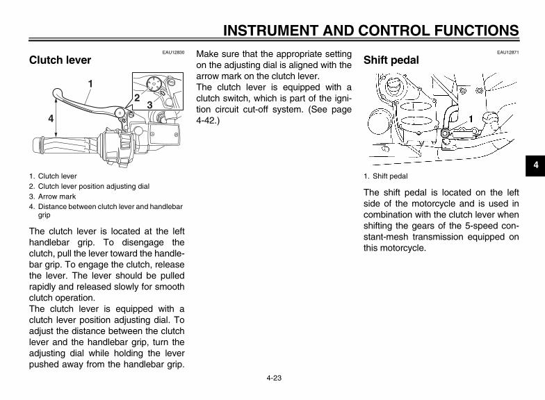
Clutch lever
The clutch lever is located at the lefthandlebar grip. To disengage theclutch, pull the lever toward the handle-bar grip. To engage the clutch, releasethe lever. The lever should be pulledrapidly and released slowly for smoothclutch operation.The clutch lever is equipped with aclutch lever position adjusting dial. Toadjust the distance between the clutchlever and the handlebar grip, turn theadjusting dial while holding the leverpushed away from the handlebar grip.
Make sure that the appropriate settingon the adjusting dial is aligned with thearrow mark on the clutch lever.The clutch lever is equipped with aclutch switch, which is part of the igni-tion circuit cut-off system. (See page4-42.)
EAU12871
Shift pedal
The shift pedal is located on the leftside of the motorcycle and is used incombination with the clutch lever whenshifting the gears of the 5-speed con-stant-mesh transmission equipped onthis motorcycle.
1. Clutch lever2. Clutch lever position adjusting dial3. Arrow mark4. Distance between clutch lever and handlebar
grip
1
5
4
3 2
4
12
3
1. Shift pedal
U1MC10E0.book Page 23 Monday, July 30, 2012 4:56 PM

INSTRUMENT AND CONTROL FUNCTIONS
4-24
4
EAU26824
Brake lever The brake lever is located on the rightside of the handlebar. To apply the frontbrake, pull the lever toward the throttlegrip.
The brake lever is equipped with abrake lever position adjusting dial. Toadjust the distance between the brakelever and the throttle grip, turn the ad-justing dial while holding the leverpushed away from the throttle grip.Make sure that the appropriate settingon the adjusting dial is aligned withthe “ ” mark on the brake lever.
EAU39540
Brake pedal
The brake pedal is on the right side ofthe vehicle.This model is equipped with a unifiedbrake system.When pressing down on the brake ped-al, the rear brake and a portion of thefront brake are applied. For full brakingperformance, apply both the brake le-ver and the brake pedal simultaneous-ly.
EAU54530
ABS The Yamaha ABS (Anti-lock BrakeSystem) features a dual electronic con-trol system, which acts on the front andrear brakes independently.Operate the brakes with ABS as youwould conventional brakes. If the ABSis activated, a pulsating sensation maybe felt at the brake lever or brake pedal.In this situation, continue to apply thebrakes and let the ABS work; do not“pump” the brakes as this will reducebraking effectiveness.
WARNINGEWA16050
Always keep a sufficient distancefrom the vehicle ahead to match theriding speed even with ABS.
● The ABS performs best withlong braking distances.
● On certain surfaces, such asrough or gravel roads, the brak-ing distance may be longer withthe ABS than without.
The ABS is monitored by an ECU,which will revert the system to conven-tional braking if a malfunction occurs.
1. Brake lever2. Brake lever position adjusting dial3. “ ” mark4. Distance between brake lever and throttle
grip
1
5
4
3 2
4
1
32
1. Brake pedal
1
U1MC10E0.book Page 24 Monday, July 30, 2012 4:56 PM

INSTRUMENT AND CONTROL FUNCTIONS
4-25
4
TIP● The ABS performs a self-diagno-
sis test each time the vehicle firststarts off after the key is turned to“ON” and the vehicle has traveledat a speed of 10 km/h (6 mi/h) orhigher. During this test, a “clicking”noise can be heard from under theseat, and if the brake lever orbrake pedal is even slightly ap-plied, a vibration can be felt at thelever and pedal, but these do notindicate a malfunction.
● This ABS has a test mode whichallows the owner to experience thepulsation at the brake lever orbrake pedal when the ABS is oper-ating. However, special tools arerequired, so please consult yourYamaha dealer when performingthis test.
NOTICEECA16830
Keep any type of magnets (includingmagnetic pick-up tools, magneticscrewdrivers, etc.) away from thefront and rear wheel hubs; other-wise, the magnetic rotors equipped
in the wheel hubs may be damaged,resulting in improper performanceof the ABS and the unified brakesystem.
EAU54270
Traction control system The traction control system helps main-tain traction when accelerating on slip-pery surfaces, such as unpaved or wetroads. If sensors detect that the rearwheel is starting to slip (uncontrolledspinning), the traction control systemassists by regulating engine power asneeded until traction is restored. The“TCS” indicator/warning light flashes tolet the rider know that traction controlhas engaged.
TIPThe rider may also notice slight chang-es in engine and exhaust sounds whenthe traction control system is engaged.
WARNINGEWA15431
The traction control system is not asubstitute for riding appropriatelyfor the conditions. Traction controlcannot prevent loss of traction dueto excessive speed when enteringturns, when accelerating hard at asharp lean angle, or while braking,and cannot prevent front wheel slip-ping. As with any motorcycle, ap-
1. Front wheel hub
1. Rear wheel hub
1
1
U1MC10E0.book Page 25 Monday, July 30, 2012 4:56 PM

INSTRUMENT AND CONTROL FUNCTIONS
4-26
4
proach surfaces that may beslippery with caution and avoid es-pecially slippery surfaces.
When the key is turned to “ON”, thetraction control system automaticallyturns on.The traction control system can beturned on or off manually only when thekey is in the “ON” position and the mo-torcycle is stopped.
TIPTurn the traction control system off tohelp free the rear wheel if the motorcy-cle gets stuck in mud, sand, or othersoft surfaces.
NOTICEECA16800
Use only the specified tires. (Seepage 7-21.) Using different sizedtires will prevent the traction controlsystem from controlling tire rotationaccurately.
Turning on/off the traction controlsystem
WARNINGEWA15440
Be sure to stop the vehicle beforemaking any setting changes to thetraction control system. Changingsettings while riding can distract theoperator and increase the risk of anaccident.
To turn off the traction control system,push the “TCS” button on the multi-function meter unit for at least 2 sec-onds. The “TCS” indicator/warning lightwill come on.To turn on the traction control system,push the “TCS” button again. The“TCS” indicator/warning light will go off.
ResettingThe traction control system will be dis-abled in the following conditions:
● The rear wheel is rotated with thecenterstand down and the key inthe “ON” position.
● Either the front wheel or rear wheelcomes off the ground while riding.
● Excessive rear wheel spinning.If the traction control system has beendisabled, both the “TCS” indica-tor/warning light and the engine troublewarning light come on.
1. “TCS” button2. Traction control system indicator/warning
light “TCS”
1 2
U1MC10E0.book Page 26 Monday, July 30, 2012 4:56 PM

INSTRUMENT AND CONTROL FUNCTIONS
4-27
4
To reset the traction control systemTurn the key to “OFF”. Wait at least 1second, then turn the key back to “ON”.The “TCS” indicator/warning lightshould go off and the system will be en-abled. The engine trouble warning lightshould go off after the motorcyclereaches at least 20 km/h (12 mi/h). Ifthe “TCS” indicator/warning light and/orengine trouble warning light still remainon after resetting, the motorcycle maystill be ridden; however, have aYamaha dealer check the motorcycleas soon as possible.
EAU13074
Fuel tank cap
To open the fuel tank capOpen the fuel tank cap lock cover, in-sert the key into the lock, and then turnit 1/4 turn clockwise. The lock will be re-leased and the fuel tank cap can beopened.
To close the fuel tank cap1. Push the fuel tank cap into position
with the key inserted in the lock.2. Turn the key counterclockwise to
the original position, remove it, andthen close the lock cover.
TIPThe fuel tank cap cannot be closed un-less the key is in the lock. In addition,the key cannot be removed if the cap isnot properly closed and locked.
WARNINGEWA11091
Make sure that the fuel tank cap isproperly closed after filling fuel.Leaking fuel is a fire hazard.
1. Unlock.2. Fuel tank cap lock cover
2
1
U1MC10E0.book Page 27 Monday, July 30, 2012 4:56 PM

INSTRUMENT AND CONTROL FUNCTIONS
4-28
4
EAU13221
Fuel Make sure there is sufficient gasoline inthe tank.
WARNINGEWA10881
Gasoline and gasoline vapors areextremely flammable. To avoid firesand explosions and to reduce therisk of injury when refueling, followthese instructions.
1. Before refueling, turn off the en-gine and be sure that no one is sit-ting on the vehicle. Never refuelwhile smoking, or while in the vi-cinity of sparks, open flames, orother sources of ignition such asthe pilot lights of water heaters andclothes dryers.
2. Do not overfill the fuel tank. Whenrefueling, be sure to insert thepump nozzle into the fuel tank fillerhole. Stop filling when the fuelreaches the bottom of the fillertube. Because fuel expands whenit heats up, heat from the engine orthe sun can cause fuel to spill outof the fuel tank.
3. Wipe up any spilled fuel immedi-ately. NOTICE: Immediately wipeoff spilled fuel with a clean, dry,soft cloth, since fuel may deteri-orate painted surfaces or plasticparts. [ECA10071]
4. Be sure to securely close the fueltank cap.
WARNINGEWA15151
Gasoline is poisonous and cancause injury or death. Handle gaso-line with care. Never siphon gaso-line by mouth. If you should swallowsome gasoline or inhale a lot of gas-oline vapor, or get some gasoline inyour eyes, see your doctor immedi-
ately. If gasoline spills on your skin,wash with soap and water. If gaso-line spills on your clothing, changeyour clothes.
EAU53060
NOTICEECA11400
Use only unleaded gasoline. The useof leaded gasoline will cause severedamage to internal engine parts,such as the valves and piston rings,as well as to the exhaust system.
Your Yamaha engine has been de-signed to use unleaded gasoline with apump octane number [(R+M)/2] of 86 orhigher, or a research octane number of91 or higher. If knocking (or pinging) oc-curs, use a gasoline of a different brand
1. Fuel tank filler tube2. Maximum fuel level
Recommended fuel:Unleaded gasoline only
Fuel tank capacity:25.0 L (6.61 US gal, 5.50 Imp.gal)
Fuel reserve amount:5.5 L (1.45 US gal, 1.21 Imp.gal)
U1MC10E0.book Page 28 Monday, July 30, 2012 4:56 PM

INSTRUMENT AND CONTROL FUNCTIONS
4-29
4
or premium unleaded fuel. Use of un-leaded fuel will extend spark plug lifeand reduce maintenance costs.GasoholThere are two types of gasohol: gaso-hol containing ethanol and that contain-ing methanol. Gasohol containingethanol can be used if the ethanol con-tent does not exceed 10% (E10). Gas-ohol containing methanol is notrecommended by Yamaha because itcan cause damage to the fuel systemor vehicle performance problems.
EAU48790
Fuel tank breather/overflow hose
TIPFor California: See page 7-13 forbreather hose information.
Before operating the motorcycle:● Check the fuel tank breather/over-
flow hose connection.● Check the fuel tank breather/over-
flow hose for cracks or damage,and replace it if damaged.
● Make sure that the end of the fueltank breather/overflow hose is notblocked, and clean it if necessary.
● Make sure that the end of the fueltank breather/overflow hose is po-sitioned inside of the clamp.
1. Fuel tank breather/overflow hose2. Clamp
2
1
U1MC10E0.book Page 29 Monday, July 30, 2012 4:56 PM

INSTRUMENT AND CONTROL FUNCTIONS
4-30
4
EAU13445
Catalytic converters This vehicle is equipped with catalyticconverters in the exhaust system.
WARNINGEWA10862
The exhaust system is hot after op-eration. To prevent a fire hazard orburns:
● Do not park the vehicle nearpossible fire hazards such asgrass or other materials thateasily burn.
● Park the vehicle in a placewhere pedestrians or childrenare not likely to touch the hotexhaust system.
● Make sure that the exhaust sys-tem has cooled down before do-ing any maintenance work.
● Do not allow the engine to idlemore than a few minutes. Longidling can cause a build-up ofheat.
NOTICEECA10701
Use only unleaded gasoline. The useof leaded gasoline will cause unre-pairable damage to the catalyticconverter.
EAU39495
Seats
Passenger seat
To remove the passenger seat1. Insert the key into the seat lock,
and then turn it counterclockwise.
2. Lift the front of the passenger seatand pull it forward.
To install the passenger seat1. Insert the projections on the rear of
the passenger seat into the seatholders as shown, and then pushthe front of the seat down to lock itin place.
1. Seat lock2. Unlock.
1
2
U1MC10E0.book Page 30 Monday, July 30, 2012 4:56 PM

INSTRUMENT AND CONTROL FUNCTIONS
4-31
4
2. Remove the key.
Rider seat
To remove the rider seat1. Remove the passenger seat.2. Push the rider seat lock lever, lo-
cated under the back of the riderseat, to the left as shown, and thenpull the seat off.
To install the rider seat1. Insert the projection on the front of
the rider seat into the seat holderas shown, and then push the rearof the seat down to lock it in place.
2. Install the passenger seat.
TIP● Make sure that the seats are prop-
erly secured before riding.● The rider seat height can be ad-
justed to change the riding posi-tion. (See the following section.)
1. Projection2. Seat holder
1. Rider seat lock lever2. Rider seat
1. Projection2. Seat holder
U1MC10E0.book Page 31 Monday, July 30, 2012 4:56 PM

INSTRUMENT AND CONTROL FUNCTIONS
4-32
4
EAU39632
Adjusting the rider seat height The rider seat height can be adjusted toone of two positions to suit the rider’spreference.The rider seat height was adjusted tothe lower position at delivery.
To change the rider seat height tothe high position
1. Remove the rider seat. (See page4-30.)
2. Remove the rider seat height posi-tion adjuster by pulling it upward.
3. Move the rider seat holder cover tothe lower position as shown.
4. Install the rider seat height positionadjuster so that the “H” mark isaligned with the match mark.
5. Insert the projection on the front ofthe rider seat into seat holder B asshown.
1. Low position2. High position
1. Rider seat height position adjuster
1. Rider seat holder cover
1
1. Rider seat height position adjuster2. “H” mark3. Match mark
1. Projection2. Seat holder B (for high position)3. Rider seat holder cover
U1MC10E0.book Page 32 Monday, July 30, 2012 4:56 PM

INSTRUMENT AND CONTROL FUNCTIONS
4-33
4
6. Align the projection on the bottomof the rider seat with the “H” posi-tion slot, and then push the rear ofthe seat down to lock it in place asshown.
7. Install the passenger seat.
To change the rider seat height tothe low position
1. Remove the rider seat. (See page4-30.)
2. Remove the rider seat height posi-tion adjuster by pulling it upward.
3. Move the rider seat holder cover tothe upper position.
4. Install the rider seat height positionadjuster so that the “L” mark isaligned with the match mark.
5. Insert the projection on the front ofthe rider seat into seat holder A asshown.
6. Align the projection on the bottomof the rider seat with the “L” posi-tion slot, and then push the rear ofthe seat down to lock it in place asshown.
7. Install the passenger seat.
TIPMake sure that the seats are properlysecured before riding.
1. “H” position slot
1. Rider seat height position adjuster2. “L” mark3. Match mark
1. Projection2. Rider seat holder cover3. Seat holder A (for low position)
12
3
1. “L” position slot
U1MC10E0.book Page 33 Monday, July 30, 2012 4:56 PM
INSTRUMENT AND CONTROL FUNCTIONS
4-34
4
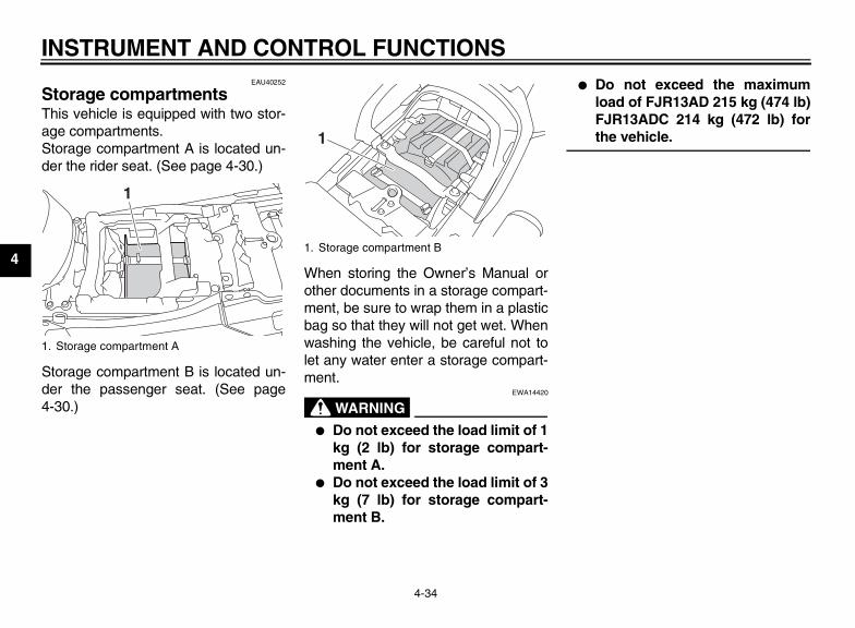
EAU40252
Storage compartments This vehicle is equipped with two stor-age compartments.Storage compartment A is located un-der the rider seat. (See page 4-30.)
Storage compartment B is located un-der the passenger seat. (See page4-30.)
When storing the Owner’s Manual orother documents in a storage compart-ment, be sure to wrap them in a plasticbag so that they will not get wet. Whenwashing the vehicle, be careful not tolet any water enter a storage compart-ment.
WARNINGEWA14420
● Do not exceed the load limit of 1kg (2 lb) for storage compart-ment A.
● Do not exceed the load limit of 3kg (7 lb) for storage compart-ment B.
● Do not exceed the maximumload of FJR13AD 215 kg (474 lb)FJR13ADC 214 kg (472 lb) forthe vehicle.
1. Storage compartment A
1
1. Storage compartment B
1
U1MC10E0.book Page 34 Monday, July 30, 2012 4:56 PM

INSTRUMENT AND CONTROL FUNCTIONS
4-35
4
EAU39480
Accessory box The accessory box is located besidethe meter panel.
To open the accessory box1. Insert the key into the main switch,
and then turn it to “ON”.2. Push the accessory box button,
and then open the accessory boxlid.
3. Turn the key to “OFF” to preservethe battery.
To close the accessory box1. Fold the accessory box lid down.
2. Remove the key.
NOTICEECA11800
Do not place heat-sensitive items inthe accessory box. The accessorybox gets extremely hot especiallywhen the engine is running or is hot.
WARNINGEWA11421
● Do not exceed the load limit of0.3 kg (0.66 lb) for the accessorybox.
● Do not exceed the maximumload of FJR13AD 215 kg (474 lb)FJR13ADC 214 kg (472 lb) forthe vehicle.
EAU39611
Adjusting the headlight beams The headlight beam adjusting knobsare used to raise or lower the height ofthe headlight beams. It may be neces-sary to adjust the headlight beams toincrease visibility and help preventblinding oncoming drivers when carry-ing more or less load than usual. Obeylocal laws and regulations when adjust-ing the headlights.To raise the headlight beams, turn theknobs in direction (a). To lower theheadlight beams, turn the knobs in di-rection (b).
1. Accessory box lid2. Accessory box3. Accessory box button
1
2 3
1. Headlight beam adjusting knob
11
(b) (a) (b) (a)
U1MC10E0.book Page 35 Monday, July 30, 2012 4:56 PM

INSTRUMENT AND CONTROL FUNCTIONS
4-36
4
EAU39641
Handlebar position The handlebars can be adjusted to oneof three positions to suit the rider’s pref-erence. Have a Yamaha dealer adjustthe position of the handlebars.
EAU54150
Opening and closing the cowl-ing vents The cowling vents can be opened 20mm (0.79 in) for added ventilation tosuit the riding conditions.
To open a cowling vent1. Remove the quick fastener.2. Slide the cowling vent panel for-
ward to unhook its projections fromthe lower slots, and then pull thepanel off.
3. Insert the projections into the up-per slots, and then slide the panelbackward.1. Handlebar
1 1
1. Closed position2. Open position
1 21. Cowling vent panel2. Lower slot3. Quick fastener
1. Projection2. Upper slot3. Quick fastener
3
1
2
1
3
2
U1MC10E0.book Page 36 Monday, July 30, 2012 4:56 PM
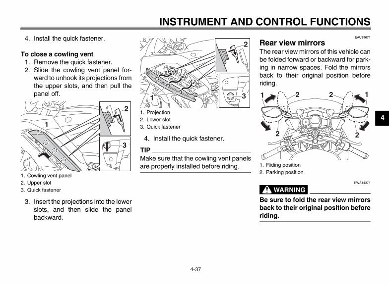
INSTRUMENT AND CONTROL FUNCTIONS
4-37
4
4. Install the quick fastener.
To close a cowling vent1. Remove the quick fastener.2. Slide the cowling vent panel for-
ward to unhook its projections fromthe upper slots, and then pull thepanel off.
3. Insert the projections into the lowerslots, and then slide the panelbackward.
4. Install the quick fastener.
TIPMake sure that the cowling vent panelsare properly installed before riding.
EAU39671
Rear view mirrors The rear view mirrors of this vehicle canbe folded forward or backward for park-ing in narrow spaces. Fold the mirrorsback to their original position beforeriding.
WARNINGEWA14371
Be sure to fold the rear view mirrorsback to their original position beforeriding.
1. Cowling vent panel2. Upper slot3. Quick fastener
3
1
21. Projection2. Lower slot3. Quick fastener
1 3
2
1. Riding position2. Parking position
2
21
2
2 1
U1MC10E0.book Page 37 Monday, July 30, 2012 4:56 PM
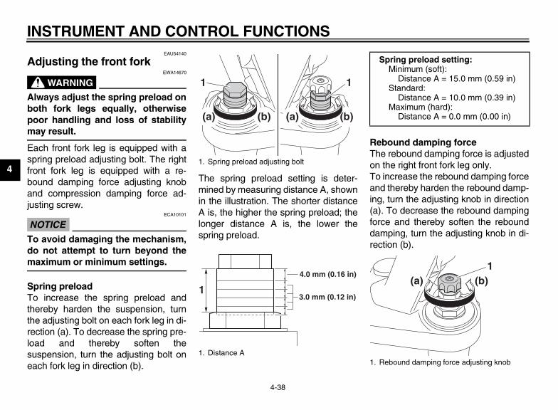
INSTRUMENT AND CONTROL FUNCTIONS
4-38
4
EAU54140
Adjusting the front fork
WARNINGEWA14670
Always adjust the spring preload onboth fork legs equally, otherwisepoor handling and loss of stabilitymay result.
Each front fork leg is equipped with aspring preload adjusting bolt. The rightfront fork leg is equipped with a re-bound damping force adjusting knoband compression damping force ad-justing screw.
NOTICEECA10101
To avoid damaging the mechanism,do not attempt to turn beyond themaximum or minimum settings.
Spring preloadTo increase the spring preload andthereby harden the suspension, turnthe adjusting bolt on each fork leg in di-rection (a). To decrease the spring pre-load and thereby soften thesuspension, turn the adjusting bolt oneach fork leg in direction (b).
The spring preload setting is deter-mined by measuring distance A, shownin the illustration. The shorter distanceA is, the higher the spring preload; thelonger distance A is, the lower thespring preload.
Rebound damping forceThe rebound damping force is adjustedon the right front fork leg only.To increase the rebound damping forceand thereby harden the rebound damp-ing, turn the adjusting knob in direction(a). To decrease the rebound dampingforce and thereby soften the rebounddamping, turn the adjusting knob in di-rection (b).
1. Spring preload adjusting bolt
1. Distance A
(a) (b)
11
(a) (b)
4.0 mm (0.16 in)
3.0 mm (0.12 in)1
Spring preload setting:Minimum (soft):
Distance A = 15.0 mm (0.59 in)Standard:
Distance A = 10.0 mm (0.39 in)Maximum (hard):
Distance A = 0.0 mm (0.00 in)
1. Rebound damping force adjusting knob
(a) (b)1
U1MC10E0.book Page 38 Monday, July 30, 2012 4:56 PM

INSTRUMENT AND CONTROL FUNCTIONS
4-39
4Compression damping forceThe compression damping force is ad-justed on the right front fork leg only.To increase the compression dampingforce and thereby harden the compres-sion damping, turn the adjusting screwin direction (a). To decrease the com-pression damping force and therebysoften the compression damping, turnthe adjusting screw in direction (b).
TIPAlthough the total number of clicks of adamping force adjusting mechanismmay not exactly match the above spec-ifications due to small differences inproduction, the actual number of clicksalways represents the entire adjustingrange. To obtain a precise adjustment,it would be advisable to check the num-
ber of clicks of each damping force ad-justing mechanism and to modify thespecifications as necessary.
Rebound damping setting:Minimum (soft):
16 click(s) in direction (b)*Standard:
12 click(s) in direction (b)*Maximum (hard):
1 click(s) in direction (b)** With the adjusting knob fully turned
in direction (a)
1. Compression damping force adjusting screw
Compression damping setting:Minimum (soft):
21 click(s) in direction (b)*Standard:
11 click(s) in direction (b)*Maximum (hard):
1 click(s) in direction (b)** With the adjusting screw fully turned
in direction (a)
U1MC10E0.book Page 39 Monday, July 30, 2012 4:56 PM

INSTRUMENT AND CONTROL FUNCTIONS
4-40
4
EAU14916
Adjusting the shock absorber assembly This shock absorber assembly isequipped with a spring preload adjust-ing lever and a rebound damping forceadjusting knob.
NOTICEECA16570
To avoid damaging the mechanism,do not attempt to move beyond themaximum or minimum settings.
Spring preloadFor riding solo, move the spring preloadadjusting lever in direction (a). Forriding with a passenger, move thespring preload adjusting lever in direc-tion (b).
Rebound damping forceTo increase the rebound damping forceand thereby harden the rebound damp-ing, turn the adjusting knob in direction(a). To decrease the rebound dampingforce and thereby soften the rebounddamping, turn the adjusting knob in di-rection (b).
TIPTo obtain a precise adjustment, it is ad-visable to check the actual total numberof clicks or turns of the damping forceadjusting mechanism. This adjustmentrange may not exactly match the spec-ifications listed due to small differencesin production.
1. Spring preload adjusting lever
1
(b)
(a)
1. Rebound damping force adjusting knob
Rebound damping setting:Minimum (soft):
20 click(s) in direction (b)*Standard:
12 click(s) in direction (b)*Maximum (hard):
3 click(s) in direction (b)** With the adjusting knob fully turned
in direction (a)
U1MC10E0.book Page 40 Monday, July 30, 2012 4:56 PM

INSTRUMENT AND CONTROL FUNCTIONS
4-41
4
WARNINGEWA10221
This shock absorber assembly con-tains highly pressurized nitrogengas. Read and understand the fol-lowing information before handlingthe shock absorber assembly.
● Do not tamper with or attempt toopen the cylinder assembly.
● Do not subject the shock ab-sorber assembly to an openflame or other high heat source.This may cause the unit to ex-plode due to excessive gaspressure.
● Do not deform or damage thecylinder in any way. Cylinderdamage will result in poordamping performance.
● Do not dispose of a damaged orworn-out shock absorber as-sembly yourself. Take the shockabsorber assembly to a Yamahadealer for any service.
EAU15305
Sidestand The sidestand is located on the left sideof the frame. Raise the sidestand orlower it with your foot while holding thevehicle upright.
TIPThe built-in sidestand switch is part ofthe ignition circuit cut-off system, whichcuts the ignition in certain situations.(See the following section for an expla-nation of the ignition circuit cut-off sys-tem.)
WARNINGEWA10241
The vehicle must not be ridden withthe sidestand down, or if the side-stand cannot be properly moved up(or does not stay up), otherwise thesidestand could contact the groundand distract the operator, resultingin a possible loss of control.Yamaha’s ignition circuit cut-offsystem has been designed to assistthe operator in fulfilling the respon-sibility of raising the sidestand be-fore starting off. Therefore, check
this system regularly and have aYamaha dealer repair it if it does notfunction properly.
U1MC10E0.book Page 41 Monday, July 30, 2012 4:56 PM
INSTRUMENT AND CONTROL FUNCTIONS
4-42
4
EAU54490
Ignition circuit cut-off system The ignition circuit cut-off system (com-prising the sidestand switch, clutchswitch and neutral switch) has the fol-lowing functions.
● It prevents starting when the trans-mission is in gear and the side-stand is up, but the clutch lever isnot pulled.
● It prevents starting when the trans-mission is in gear and the clutch le-ver is pulled, but the sidestand isstill down.
● It cuts the running engine when thetransmission is in gear and thesidestand is moved down.
Periodically check the operation of theignition circuit cut-off system accordingto the following procedure.
U1MC10E0.book Page 42 Monday, July 30, 2012 4:56 PM

INSTRUMENT AND CONTROL FUNCTIONS
4-43
4
With the engine turned off:1. Move the sidestand down.2. Make sure that the start/engine stop switch is set to “ ”.3. Turn the key on. 4. Shift the transmission into the neutral position.5. Push the “ ” side of the start/engine stop switch.Does the engine start?
With the engine still running:6. Move the sidestand up.7. Keep the clutch lever pulled.8. Shift the transmission into gear.9. Move the sidestand down.Does the engine stall?
After the engine has stalled:10. Move the sidestand up.11. Keep the clutch lever pulled.12. Push the “ ” side of the start/engine stop switch.Does the engine start?
The system is OK. The motorcycle can be ridden.
YES NO
YES NO
YES NO
The neutral switch may not be working correctly.The motorcycle should not be ridden untilchecked by a Yamaha dealer.
The clutch switch may not be working correctly.The motorcycle should not be ridden untilchecked by a Yamaha dealer.
The sidestand switch may not be working correctly.The motorcycle should not be ridden untilchecked by a Yamaha dealer.
• The vehicle must be placed on the center- stand during this inspection.• If a malfunction is noted, have a Yamaha dealer check the system before riding.
WARNING
U1MC10E0.book Page 43 Monday, July 30, 2012 4:56 PM

INSTRUMENT AND CONTROL FUNCTIONS
4-44
4
EAU39655
Auxiliary DC jack
WARNINGEWA14360
To prevent electrical shock or short-circuiting, make sure that the cap isinstalled when the auxiliary DC jackis not being used.
NOTICEECA15431
The accessory connected to theauxiliary DC jack should not be usedwith the engine turned off, and theload must never exceed 30 W (2.5 A),otherwise the fuse may blow or thebattery may discharge.
This vehicle is equipped with an auxilia-ry DC jack in the accessory box.A 12-V accessory connected to theauxiliary jack can be used when the keyis in the “ON” position and should onlybe used when the engine is running.
To use the auxiliary DC jack1. Open the accessory box lid. (See
page 4-35.)2. Turn the key to “OFF”.3. Remove the auxiliary DC jack cap.
4. Turn the accessory off.5. Insert the accessory plug into the
auxiliary DC jack.
6. Turn the key to “ON”, and thenstart the engine. (See page 6-1.)
7. Turn the accessory on.
1. Auxiliary DC jack cap
1. Auxiliary DC jack
1
1
U1MC10E0.book Page 44 Monday, July 30, 2012 4:56 PM

FOR YOUR SAFETY – PRE-OPERATION CHECKS
5-1
5
EAU15596
Inspect your vehicle each time you use it to make sure the vehicle is in safe operating condition. Always follow the inspectionand maintenance procedures and schedules described in the Owner’s Manual.
WARNINGEWA11151
Failure to inspect or maintain the vehicle properly increases the possibility of an accident or equipment damage.Do not operate the vehicle if you find any problem. If a problem cannot be corrected by the procedures provided inthis manual, have the vehicle inspected by a Yamaha dealer.
Before using this vehicle, check the following points:
ITEM CHECKS PAGE
Fuel
• Check fuel level in fuel tank.• Refuel if necessary.• Check fuel line for leakage.• Check fuel tank breather/overflow hose for obstructions, cracks or damage, and
check hose connection.
4-28, 4-29
Engine oil• Check oil level in engine.• If necessary, add recommended oil to specified level.• Check vehicle for oil leakage.
7-13
Final gear oil • Check vehicle for oil leakage. 7-16
Coolant• Check coolant level in reservoir.• If necessary, add recommended coolant to specified level.• Check cooling system for leakage.
7-17
Front brake
• Check operation.• If soft or spongy, have Yamaha dealer bleed hydraulic system.• Check brake pads for wear.• Replace if necessary.• Check fluid level in reservoir.• If necessary, add specified brake fluid to specified level.• Check hydraulic system for leakage.
7-25, 7-26
U1MC10E0.book Page 1 Monday, July 30, 2012 4:56 PM

FOR YOUR SAFETY – PRE-OPERATION CHECKS
5-2
5
Rear brake
• Check operation.• If soft or spongy, have Yamaha dealer bleed hydraulic system.• Check brake pads for wear.• Replace if necessary.• Check fluid level in reservoir.• If necessary, add specified brake fluid to specified level.• Check hydraulic system for leakage.
7-25, 7-26
Clutch
• Check operation.• If soft or spongy, have Yamaha dealer bleed hydraulic system.• Check fluid level in reservoir.• If necessary, add specified brake fluid to specified level.• Check hydraulic system for leakage.
7-24, 7-26
Throttle grip
• Make sure that operation is smooth.• Check throttle grip free play.• If necessary, have Yamaha dealer adjust throttle grip free play and lubricate cable
and grip housing.
7-20, 7-28
Control cables • Make sure that operation is smooth.• Lubricate if necessary. 7-27
Wheels and tires
• Check for damage.• Check tire condition and tread depth.• Check air pressure.• Correct if necessary.
7-21, 7-23
Brake and shift pedals • Make sure that operation is smooth.• Lubricate pedal pivoting points if necessary. 7-28
Brake and clutch levers • Make sure that operation is smooth.• Lubricate lever pivoting points if necessary. 7-29
Centerstand, sidestand • Make sure that operation is smooth.• Lubricate pivots if necessary. 7-29
Chassis fasteners • Make sure that all nuts, bolts and screws are properly tightened.• Tighten if necessary. —
ITEM CHECKS PAGE
U1MC10E0.book Page 2 Monday, July 30, 2012 4:56 PM

FOR YOUR SAFETY – PRE-OPERATION CHECKS
5-3
5
Instruments, lights, signals and switches
• Check operation.• Correct if necessary. —
Sidestand switch • Check operation of ignition circuit cut-off system.• If system is not working correctly, have Yamaha dealer check vehicle. 4-41
ITEM CHECKS PAGE
U1MC10E0.book Page 3 Monday, July 30, 2012 4:56 PM

OPERATION AND IMPORTANT RIDING POINTS
6-1
6
EAU15951
Read the Owner’s Manual carefully tobecome familiar with all controls. Ifthere is a control or function you do notunderstand, ask your Yamaha dealer.
WARNINGEWA10271
Failure to familiarize yourself withthe controls can lead to loss of con-trol, which could cause an accidentor injury.
EAU47150
TIPThis model is equipped with:
● a lean angle sensor to stop the en-gine in case of a turnover. In thiscase, the multi-function meter unitindicates error code 30, but this isnot a malfunction. Turn the key to“OFF” and then to “ON” to clear theerror code. Failing to do so will pre-vent the engine from starting eventhough the engine will crank whenpushing the start switch.
● an engine auto-stop system. Theengine stops automatically if leftidling for 20 minutes. In this case,the multi-function meter unit indi-cates error code 70, but this is nota malfunction. Push the startswitch to clear the error code andto restart the engine.
EAU54750
Starting the engine In order for the ignition circuit cut-offsystem to enable starting, one of thefollowing conditions must be met:
● The transmission is in the neutralposition.
● The transmission is in gear withthe clutch lever pulled and thesidestand up.See page 4-42 for more informa-tion.
1. Turn the key to “ON” and makesure that the start/engine stopswitch is set to “ ”.The following warning lights andindicator lights should come on fora few seconds, then go off.
● Oil level warning light● Engine trouble warning light● Traction control system indi-
cator/warning light● Cruise control indicator lights
NOTICEECA11833
If a warning or indicator light doesnot come on initially when the key isturned to “ON”, or if a warning or in-
U1MC10E0.book Page 1 Monday, July 30, 2012 4:56 PM

OPERATION AND IMPORTANT RIDING POINTS
6-2
6
dicator light remains on, see page4-2 for the corresponding warningand indicator light circuit check.
The ABS warning light shouldcome on when the key is turned to“ON”, and then go off after travel-ing at a speed of 10 km/h (6 mi/h)or higher.
NOTICEECA17681
If the ABS warning light does notcome on and then go off as ex-plained above, see page 4-2 for thewarning light circuit check.
2. Shift the transmission into the neu-tral position. The neutral indicatorlight should come on. If not, ask aYamaha dealer to check the elec-trical circuit.
3. Start the engine by pushingthe “ ” side of the start/enginestop switch.If the engine fails to start, releasethe start/engine stop switch, wait afew seconds, and then try again.Each starting attempt should be asshort as possible to preserve the
battery. Do not crank the enginemore than 10 seconds on any oneattempt.
NOTICEECA11042
For maximum engine life, never ac-celerate hard when the engine iscold!
EAU16671
Shifting
Shifting gears lets you control theamount of engine power available forstarting off, accelerating, climbing hills,etc.The gear positions are shown in the il-lustration.
TIPTo shift the transmission into the neu-tral position, press the shift pedal downrepeatedly until it reaches the end of itstravel, and then slightly raise it.
1. Shift pedal2. Neutral position
U1MC10E0.book Page 2 Monday, July 30, 2012 4:56 PM

OPERATION AND IMPORTANT RIDING POINTS
6-3
6
NOTICEECA10260
● Even with the transmission inthe neutral position, do notcoast for long periods of timewith the engine off, and do nottow the motorcycle for long dis-tances. The transmission isproperly lubricated only whenthe engine is running. Inade-quate lubrication may damagethe transmission.
● Always use the clutch whilechanging gears to avoid damag-ing the engine, transmission,and drive train, which are notdesigned to withstand theshock of forced shifting.
EAU16681
To start out and accelerate1. Pull the clutch lever to disengage
the clutch.2. Shift the transmission into first
gear. The neutral indicator lightshould go out.
3. Open the throttle gradually, and atthe same time, release the clutchlever slowly.
4. At the recommended shift pointsshown in the following table, closethe throttle, and at the same time,quickly pull the clutch lever in.
5. Shift the transmission into secondgear. (Make sure not to shift thetransmission into the neutral posi-tion.)
6. Open the throttle part way andgradually release the clutch lever.
7. Follow the same procedure whenshifting to the next higher gear.
TIPWhen shifting gears in normal operat-ing conditions, use the recommendedshift points.
EAU16700
To decelerate1. Apply both the front and the rear
brakes to slow the motorcycle.2. Shift the transmission into first
gear when the motorcycle reaches25 km/h (16 mi/h). If the engine isabout to stall or runs very roughly,pull the clutch lever in and use thebrakes to stop the motorcycle.
3. Shift the transmission into the neu-tral position when the motorcycleis almost completely stopped. Theneutral indicator light should comeon.
EAU16720
Recommended shift pointsThe recommended shift points duringacceleration and deceleration areshown in the table below.
Shift up points:1st → 2nd: 20 km/h (12 mi/h)2nd → 3rd: 30 km/h (19 mi/h)3rd → 4th: 40 km/h (25 mi/h)4th → 5th: 50 km/h (31 mi/h)
Shift down points:5th → 4th: 25 km/h (16 mi/h)4th → 3rd: 25 km/h (16 mi/h)3rd → 2nd: 25 km/h (16 mi/h)2nd → 1st: 25 km/h (16 mi/h)
U1MC10E0.book Page 3 Monday, July 30, 2012 4:56 PM

OPERATION AND IMPORTANT RIDING POINTS
6-4
6
EAU16841
Engine break-in There is never a more important periodin the life of your engine than the periodbetween 0 and 1600 km (1000 mi). Forthis reason, you should read the follow-ing material carefully.Since the engine is brand new, do notput an excessive load on it for the first1600 km (1000 mi). The various parts inthe engine wear and polish themselvesto the correct operating clearances.During this period, prolonged full-throt-tle operation or any condition that mightresult in engine overheating must beavoided.
EAU17123
0–1000 km (0–600 mi)Avoid prolonged operation above 4500r/min. NOTICE: After 1000 km (600mi) of operation, the engine oil andfinal gear oil must be changed, andthe oil filter cartridge or element re-placed. [ECA10332]
1000–1600 km (600–1000 mi)Avoid prolonged operation above 5400r/min.
1600 km (1000 mi) and beyondThe vehicle can now be operated nor-mally.
NOTICEECA10310
● Keep the engine speed out ofthe tachometer red zone.
● If any engine trouble should oc-cur during the engine break-inperiod, immediately have aYamaha dealer check the vehi-cle.
EAU17213
Parking When parking, stop the engine, andthen remove the key from the mainswitch.
WARNINGEWA10311
● Since the engine and exhaustsystem can become very hot,park in a place where pedestri-ans or children are not likely totouch them and be burned.
● Do not park on a slope or on softground, otherwise the vehiclemay overturn, increasing therisk of a fuel leak and fire.
● Do not park near grass or otherflammable materials whichmight catch fire.
U1MC10E0.book Page 4 Monday, July 30, 2012 4:56 PM

PERIODIC MAINTENANCE AND ADJUSTMENT
7-1
7
EAU17244
Periodic inspection, adjustment, and lu-brication will keep your vehicle in thesafest and most efficient condition pos-sible. Safety is an obligation of the vehi-cle owner/operator. The most importantpoints of vehicle inspection, adjust-ment, and lubrication are explained onthe following pages.The intervals given in the periodicmaintenance charts should be simplyconsidered as a general guide undernormal riding conditions. However, de-pending on the weather, terrain, geo-graphical location, and individual use,the maintenance intervals may need tobe shortened.
WARNINGEWA10321
Failure to properly maintain the ve-hicle or performing maintenance ac-tivities incorrectly may increaseyour risk of injury or death duringservice or while using the vehicle. Ifyou are not familiar with vehicle ser-vice, have a Yamaha dealer performservice.
WARNINGEWA15122
Turn off the engine when performingmaintenance unless otherwisespecified.
● A running engine has movingparts that can catch on bodyparts or clothing and electricalparts that can cause shocks orfires.
● Running the engine while ser-vicing can lead to eye injury,burns, fire, or carbon monoxidepoisoning – possibly leading todeath. See page 2-3 for more in-formation about carbon monox-ide.
WARNINGEWA15460
Brake discs, calipers, drums, andlinings can become very hot duringuse. To avoid possible burns, letbrake components cool beforetouching them.
EAU17302
Emission controls not only function toensure cleaner air, but are also vital toproper engine operation and maximumperformance. In the following periodicmaintenance charts, the services relat-ed to emissions control are groupedseparately. These services requirespecialized data, knowledge, andequipment. Maintenance, replacement,or repair of the emission control devic-es and systems may be performed byany repair establishment or individualthat is certified (if applicable). Yamahadealers are trained and equipped toperform these particular services.
U1MC10E0.book Page 1 Monday, July 30, 2012 4:56 PM
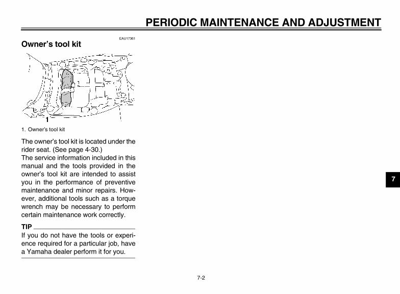
PERIODIC MAINTENANCE AND ADJUSTMENT
7-2
7
EAU17361
Owner’s tool kit
The owner’s tool kit is located under therider seat. (See page 4-30.)The service information included in thismanual and the tools provided in theowner’s tool kit are intended to assistyou in the performance of preventivemaintenance and minor repairs. How-ever, additional tools such as a torquewrench may be necessary to performcertain maintenance work correctly.
TIPIf you do not have the tools or experi-ence required for a particular job, havea Yamaha dealer perform it for you.
1. Owner’s tool kit
U1MC10E0.book Page 2 Monday, July 30, 2012 4:56 PM

PERIODIC MAINTENANCE AND ADJUSTMENT
7-3
7
EAU48490
TIP● From 24000 mi (37000 km) or 36 months, repeat the maintenance intervals starting from 8000 mi (13000 km) or 12
months.● Items marked with an asterisk require special tools, data and technical skills, have a Yamaha dealer perform the service.
EAU17601
Periodic maintenance chart for the emission control system
No. ITEM ROUTINE
INITIAL ODOMETER READINGS
600 mi (1000 km)
or 1 month
4000 mi (7000 km)
or 6 months
8000 mi (13000 km)
or 12 months
12000 mi (19000 km)
or 18 months
16000 mi (25000 km)
or 24 months
20000 mi (31000 km)
or 30 months
1 * Fuel line• Check fuel hoses for cracks or
damage.• Replace if necessary.
√ √ √ √ √
2 * Spark plugs
• Check condition.• Adjust gap and clean.• Replace every 8000 mi (13000
km) or 12 months.
√ Replace. √ Replace. √
3 * Valve clearance • Check and adjust valve clearance when engine is cold. Every 26600 mi (42000 km)
4 * Crankcase breather system
• Check breather hose for cracks or damage.
• Replace if necessary.√ √ √ √ √
5 * Fuel injection • Adjust synchronization. √ √ √ √ √ √
6 * Exhaust system• Check for leakage.• Tighten if necessary.• Replace gasket(s) if necessary.
√ √ √ √ √
U1MC10E0.book Page 3 Monday, July 30, 2012 4:56 PM

PERIODIC MAINTENANCE AND ADJUSTMENT
7-4
7
7 *Evaporative emis-sion control system (for California only)
• Check control system for dam-age.
• Replace if necessary.√ √
8 * Air induction sys-tem
• Check the air cut-off valve, reed valve, and hose for damage.
• Replace any damaged parts.√ √
No. ITEM ROUTINE
INITIAL ODOMETER READINGS
600 mi (1000 km)
or 1 month
4000 mi (7000 km)
or 6 months
8000 mi (13000 km)
or 12 months
12000 mi (19000 km)
or 18 months
16000 mi (25000 km)
or 24 months
20000 mi (31000 km)
or 30 months
U1MC10E0.book Page 4 Monday, July 30, 2012 4:56 PM

PERIODIC MAINTENANCE AND ADJUSTMENT
7-5
7
EAU32188
General maintenance and lubrication chart
No. ITEM ROUTINE
INITIAL ODOMETER READINGS
600 mi (1000 km)
or 1 month
4000 mi (7000 km)
or 6 months
8000 mi (13000 km)
or 12 months
12000 mi (19000 km)
or 18 months
16000 mi (25000 km)
or 24 months
20000 mi (31000 km)
or 30 months
1 Air filter element • Clean with compressed air.• Replace if necessary. √ √ √ √ √
2 * Clutch• Check operation and fluid leak-
age.• Correct if necessary.
√ √ √ √ √ √
3 * Front brake• Check operation, fluid level, and
for fluid leakage.• Replace brake pads if necessary.
√ √ √ √ √ √
4 * Rear brake• Check operation, fluid level, and
for fluid leakage.• Replace brake pads if necessary.
√ √ √ √ √ √
5 * Brake hoses
• Check for cracks or damage.• Check for correct routing and
clamping.√ √ √ √ √
• Replace. Every 4 years
6 * Brake fluid • Replace. Every 2 years
7 * Wheels • Check runout and for damage.• Replace if necessary. √ √ √ √ √
8 * Tires
• Check tread depth and for dam-age.
• Replace if necessary.• Check air pressure.• Correct if necessary.
√ √ √ √ √
U1MC10E0.book Page 5 Monday, July 30, 2012 4:56 PM

PERIODIC MAINTENANCE AND ADJUSTMENT
7-6
7
9 * Wheel bearings• Check bearings for smooth oper-
ation.• Replace if necessary.
√ √ √ √ √
10 * Swingarm pivot bearings
• Check bearing assemblies for looseness.
• Moderately repack with lithium-soap-based grease.
√ Repack.
11 * Steering bearings
• Check bearing assemblies for looseness. √ √ √ √ √ √
• Moderately repack with lithium-soap-based grease. Every 16000 mi (25000 km)
12 * Chassis fasteners• Check all chassis fitting and fas-
teners.• Correct if necessary.
√ √ √ √ √
13 Brake lever pivot shaft • Apply silicone grease lightly. √ √ √ √ √
14 Brake pedal pivot shaft
• Apply lithium-soap-based grease lightly. √ √ √ √ √
15 Clutch lever pivot shaft • Apply silicone grease lightly. √ √ √ √ √
16 Shift pedal pivot shaft
• Apply lithium-soap-based grease lightly. √ √ √ √ √
17 * Centerstand and sidestand pivots
• Check operation.• Apply lithium-soap-based grease
lightly.√ √ √ √ √
No. ITEM ROUTINE
INITIAL ODOMETER READINGS
600 mi (1000 km)
or 1 month
4000 mi (7000 km)
or 6 months
8000 mi (13000 km)
or 12 months
12000 mi (19000 km)
or 18 months
16000 mi (25000 km)
or 24 months
20000 mi (31000 km)
or 30 months
U1MC10E0.book Page 6 Monday, July 30, 2012 4:56 PM
PERIODIC MAINTENANCE AND ADJUSTMENT
7-7
7
18 * Sidestand switch • Check operation and replace if necessary. √ √ √ √ √ √
19 * Front fork• Check operation and for oil leak-
age.• Replace if necessary.
√ √ √ √ √
20 * Shock absorber as-sembly
• Check operation and for oil leak-age.
• Replace if necessary.√ √ √ √ √
21 * Rear suspension link pivots
• Apply lithium-soap-based grease lightly. √
22 Engine oil • Change (warm engine before draining). √ √ √ √ √ √
23 Engine oil filter car-tridge • Replace. √ √ √
24 * Cooling system
• Check hoses for cracks or dam-age.
• Replace if necessary.√ √ √ √ √
• Change coolant. √
25 * Final gear oil
• Check oil level and for leakage.• Change at initial 600 mi (1000
km) or 1 month, and thereafter every 16000 mi (25000 km) or 24 months.
Change. √ Change.
26 * Front and rear brake switches • Check operation. √ √ √ √ √ √
No. ITEM ROUTINE
INITIAL ODOMETER READINGS
600 mi (1000 km)
or 1 month
4000 mi (7000 km)
or 6 months
8000 mi (13000 km)
or 12 months
12000 mi (19000 km)
or 18 months
16000 mi (25000 km)
or 24 months
20000 mi (31000 km)
or 30 months
U1MC10E0.book Page 7 Monday, July 30, 2012 4:56 PM

PERIODIC MAINTENANCE AND ADJUSTMENT
7-8
7
EAU17660
TIP● The air filter needs more frequent service if you are riding in unusually wet or dusty areas.● Hydraulic brake and clutch systems
• After disassembling the brake or clutch master cylinders, caliper cylinders or clutch release cylinder, always changethe fluid. Regularly check the brake and clutch fluid levels and fill the reservoirs as required.
• Replace the oil seals on the inner parts of the brake or clutch master cylinders, caliper cylinders and clutch releasecylinder every two years.
• Replace the brake and clutch hoses every four years or if cracked or damaged.
27 * Control cables • Apply Yamaha chain and cable lube or engine oil thoroughly. √ √ √ √ √ √
28 * Throttle grip
• Check operation.• Check throttle grip free play, and
adjust if necessary.• Lubricate cable and grip housing.
√ √ √ √ √
29 * Lights, signals and switches
• Check operation.• Adjust headlight beam. √ √ √ √ √ √
No. ITEM ROUTINE
INITIAL ODOMETER READINGS
600 mi (1000 km)
or 1 month
4000 mi (7000 km)
or 6 months
8000 mi (13000 km)
or 12 months
12000 mi (19000 km)
or 18 months
16000 mi (25000 km)
or 24 months
20000 mi (31000 km)
or 30 months
U1MC10E0.book Page 8 Monday, July 30, 2012 4:56 PM

PERIODIC MAINTENANCE AND ADJUSTMENT
7-9
7
EAU18771
Removing and installing pan-els The panels shown need to be removedto perform some of the maintenancejobs described in this chapter. Refer tothis section each time a panel needs tobe removed and installed.
EAU54130
Panel A
To remove the panel1. Remove each headlight beam ad-
justing knob by removing thescrew.
2. Remove the bolts and the quickfasteners.
1. Panel A1
1. Panel B
1. Panel C
1
1
1. Screw2. Headlight beam adjusting knob
12
U1MC10E0.book Page 9 Monday, July 30, 2012 4:56 PM
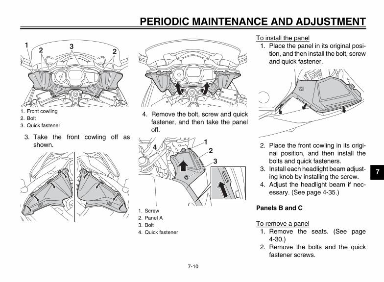
PERIODIC MAINTENANCE AND ADJUSTMENT
7-10
7
3. Take the front cowling off asshown.
4. Remove the bolt, screw and quickfastener, and then take the paneloff.
To install the panel1. Place the panel in its original posi-
tion, and then install the bolt, screwand quick fastener.
2. Place the front cowling in its origi-nal position, and then install thebolts and quick fasteners.
3. Install each headlight beam adjust-ing knob by installing the screw.
4. Adjust the headlight beam if nec-essary. (See page 4-35.)
Panels B and C
To remove a panel1. Remove the seats. (See page
4-30.)2. Remove the bolts and the quick
fastener screws.
1. Front cowling2. Bolt3. Quick fastener
221 3
1. Screw2. Panel A3. Bolt4. Quick fastener
1
324
U1MC10E0.book Page 10 Monday, July 30, 2012 4:56 PM

PERIODIC MAINTENANCE AND ADJUSTMENT
7-11
7
3. Pull the bottom of the panel out-ward, pull the front of the paneldownward, and then slide the pan-el forward to release it in the rearas shown.
To install a panel1. Place the panel in the original posi-
tion, and then install the bolts andthe quick fastener screws.
2. Install the seats.
1. Panel B2. Quick fastener screw3. Bolt
1. Panel C2. Quick fastener screw3. Bolt
1 2
2
3
3
23
12 2
2
33 1. Panel B
1
1. Panel B
1
U1MC10E0.book Page 11 Monday, July 30, 2012 4:56 PM

PERIODIC MAINTENANCE AND ADJUSTMENT
7-12
7
EAU19652
Checking the spark plugs The spark plugs are important enginecomponents, which should be checkedperiodically, preferably by a Yamahadealer. Since heat and deposits willcause any spark plug to slowly erode,they should be removed and checkedin accordance with the periodic mainte-nance and lubrication chart. In addition,the condition of the spark plugs can re-veal the condition of the engine.The porcelain insulator around the cen-ter electrode of each spark plug shouldbe a medium-to-light tan (the ideal colorwhen the vehicle is ridden normally),and all spark plugs installed in the en-gine should have the same color. If anyspark plug shows a distinctly differentcolor, the engine could be operating im-properly. Do not attempt to diagnosesuch problems yourself. Instead, havea Yamaha dealer check the vehicle.If a spark plug shows signs of electrodeerosion and excessive carbon or otherdeposits, it should be replaced.
Before installing a spark plug, the sparkplug gap should be measured with awire thickness gauge and, if necessary,adjusted to specification.
Clean the surface of the spark pluggasket and its mating surface, and thenwipe off any grime from the spark plugthreads.
TIPIf a torque wrench is not available wheninstalling a spark plug, a good estimateof the correct torque is 1/4–1/2 turnpast finger tight. However, the sparkplug should be tightened to the speci-fied torque as soon as possible.
NOTICEECA10840
Do not use any tools to remove or in-stall the spark plug cap, otherwisethe ignition coil coupler may getdamaged. The spark plug cap maybe difficult to remove because therubber seal on the end of the cap fitstightly. To remove the spark plugcap, simply twist it back and forthwhile pulling it out; to install it, twistit back and forth while pushing it in.
Specified spark plug:NGK/CPR8EA-9
1. Spark plug gap
Spark plug gap:0.8–0.9 mm (0.031–0.035 in)
Tightening torque:Spark plug:
13 Nm (1.3 m·kgf, 9.4 ft·lbf)
U1MC10E0.book Page 12 Monday, July 30, 2012 4:56 PM

PERIODIC MAINTENANCE AND ADJUSTMENT
7-13
7
EAU19681
Canister (for California only)
This model is equipped with a canisterto prevent the discharging of fuel vaporinto the atmosphere. Before operatingthis vehicle, make sure to check the fol-lowing:
● Check each hose connection.● Check each hose and canister for
cracks or damage. Replace if dam-aged.
● Make sure that the canister breath-er is not blocked, and if necessary,clean it.
EAU19886
Engine oil and oil filter car-tridge The engine oil level should be checkedbefore each ride. In addition, the oilmust be changed and the oil filter car-tridge replaced at the intervals speci-fied in the periodic maintenance andlubrication chart.
To check the engine oil level1. Place the vehicle on the center-
stand. A slight tilt to the side canresult in a false reading.
2. Start the engine, warm it up forseveral minutes, and then turn itoff.
3. Wait a few minutes until the oil set-tles, and then check the oil levelthrough the check window locatedat the bottom-left side of the crank-case.
TIPThe engine oil should be between theminimum and maximum level marks.
4. If the engine oil is below the mini-mum level mark, add sufficient oilof the recommended type to raiseit to the correct level.
To change the engine oil (with orwithout oil filter cartridge replace-ment)
1. Place the vehicle on a level sur-face.
2. Start the engine, warm it up forseveral minutes, and then turn itoff.
3. Place an oil pan under the engineto collect the used oil.
#4#3
#2#1
FUEL TANK
THROTTLE BODYCHARCOALCANISTER
ATMOSPHERE
1. Engine oil level check window2. Engine oil filler cap3. Maximum level mark4. Minimum level mark
31
4
2
U1MC10E0.book Page 13 Monday, July 30, 2012 4:56 PM
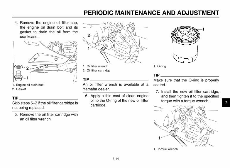
PERIODIC MAINTENANCE AND ADJUSTMENT
7-14
7
4. Remove the engine oil filler cap,the engine oil drain bolt and itsgasket to drain the oil from thecrankcase.
TIPSkip steps 5–7 if the oil filter cartridge isnot being replaced.
5. Remove the oil filter cartridge withan oil filter wrench.
TIPAn oil filter wrench is available at aYamaha dealer.
6. Apply a thin coat of clean engineoil to the O-ring of the new oil filtercartridge.
TIPMake sure that the O-ring is properlyseated.
7. Install the new oil filter cartridge,and then tighten it to the specifiedtorque with a torque wrench.
1. Engine oil drain bolt2. Gasket
1
2 1. Oil filter wrench2. Oil filter cartridge
1
2
1. O-ring
1. Torque wrench
1
U1MC10E0.book Page 14 Monday, July 30, 2012 4:56 PM

PERIODIC MAINTENANCE AND ADJUSTMENT
7-15
7
8. Install the engine oil drain bolt andits new gasket, and then tightenthe bolt to the specified torque.
9. Refill with the specified amount ofthe recommended engine oil, andthen install and tighten the oil fillercap.
TIPBe sure to wipe off spilled oil on anyparts after the engine and exhaust sys-tem have cooled down.
NOTICEECA11620
● In order to prevent clutch slip-page (since the engine oil alsolubricates the clutch), do notmix any chemical additives. Donot use oils with a diesel speci-fication of “CD” or oils of a high-er quality than specified. Inaddition, do not use oils labeled“ENERGY CONSERVING II” orhigher.
● Make sure that no foreign mate-rial enters the crankcase.
10. Start the engine, and then let it idlefor several minutes while checkingit for oil leakage. If oil is leaking, im-mediately turn the engine off andcheck for the cause.
TIPAfter the engine is started, the engineoil level warning light should go off if theoil level is sufficient.
NOTICEECA10401
If the oil level warning light flickersor remains on even if the oil level iscorrect, immediately turn the engineoff and have a Yamaha dealer checkthe vehicle.
11. Turn the engine off, and thencheck the oil level and correct it ifnecessary.
Tightening torque:Oil filter cartridge:
17 Nm (1.7 m·kgf, 12 ft·lbf)
Tightening torque:Engine oil drain bolt:
43 Nm (4.3 m·kgf, 31 ft·lbf)
Recommended engine oil:See page 9-1.
Oil quantity:Without oil filter cartridge replace-ment:
3.80 L (4.02 US qt, 3.34 Imp.qt)With oil filter cartridge replacement:
4.00 L (4.23 US qt, 3.52 Imp.qt)
U1MC10E0.book Page 15 Monday, July 30, 2012 4:56 PM

PERIODIC MAINTENANCE AND ADJUSTMENT
7-16
7
EAU20016
Final gear oil The final gear case must be checkedfor oil leakage before each ride. If anyleakage is found, have a Yamaha deal-er check and repair the vehicle. In addi-tion, the final gear oil level must bechecked and the oil changed as followsat the intervals specified in the periodicmaintenance and lubrication chart.
WARNINGEWA10370
● Make sure that no foreign mate-rial enters the final gear case.
● Make sure that no oil gets on thetire or wheel.
To check the final gear oil level1. Place the vehicle on the center-
stand.
TIPMake sure that the vehicle is positionedstraight up when checking the oil level.A slight tilt to the side can result in afalse reading.
2. Remove the final gear oil filler boltand its gasket, and then check theoil level in the final gear case.
TIPThe oil level should be at the brim of thefiller hole.
3. If the oil is below the brim of the fill-er hole, add sufficient oil of the rec-ommended type to raise it to thecorrect level.
4. Check the gasket for damage, andreplace it if necessary.
5. Install the final gear oil filler boltand its gasket, and then tighten thebolt to the specified torque.
To change the final gear oil1. Place the vehicle on a level sur-
face.2. Place an oil pan under the final
gear case to collect the used oil.3. Remove the final gear oil filler bolt,
the final gear oil drain bolt and theirgasket to drain the oil from the finalgear case.
4. Install the final gear oil drain boltand its new gasket, and then tight-en the bolt to the specified torque.
1. Final gear oil filler bolt2. Gasket3. Correct oil level
3
2
1
Tightening torque:Final gear oil filler bolt:
23 Nm (2.3 m·kgf, 17 ft·lbf)
1. Final gear oil filler bolt2. Gasket3. Final gear oil drain bolt
1
2
3
2
U1MC10E0.book Page 16 Monday, July 30, 2012 4:56 PM

PERIODIC MAINTENANCE AND ADJUSTMENT
7-17
7
5. Refill with the recommended finalgear oil to the brim of the filler hole.
6. Check the oil filler bolt gasket fordamage, and replace it if neces-sary.
7. Install the oil filler bolt and its gas-ket, and then tighten the bolt to thespecified torque.
8. Check the final gear case for oilleakage. If oil is leaking, check forthe cause.
EAU20070
Coolant The coolant level should be checkedbefore each ride. In addition, the cool-ant must be changed at the intervalsspecified in the periodic maintenanceand lubrication chart.
EAU54160
To check the coolant level1. Place the vehicle on the center-
stand.
TIP● The coolant level must be checked
on a cold engine since the levelvaries with engine temperature.
● Make sure that the vehicle is posi-tioned straight up when checkingthe coolant level. A slight tilt to theside can result in a false reading.
2. Remove the left cowling vent pan-el. (See page 4-36.)
3. Check the coolant level in the cool-ant reservoir.
TIPThe coolant should be between theminimum and maximum level marks.
4. If the coolant is at or below theminimum level mark, remove thecoolant reservoir cap.
5. Add coolant or distilled water toraise the coolant to the maximumlevel mark, and install the coolant
Tightening torque:Final gear oil drain bolt:
23 Nm (2.3 m·kgf, 17 ft·lbf)
Recommended final gear oil:Yamaha genuine shaft drive gear oil SAE 80 API GL-5
Oil quantity:0.20 L (0.21 US qt, 0.18 Imp.qt)
Tightening torque:Final gear oil filler bolt:
23 Nm (2.3 m·kgf, 17 ft·lbf)
1. Maximum level mark2. Minimum level mark
1. Coolant reservoir cap
12
1
U1MC10E0.book Page 17 Monday, July 30, 2012 4:56 PM

PERIODIC MAINTENANCE AND ADJUSTMENT
7-18
7
reservoir cap. WARNING! Re-move only the coolant reservoircap. Never attempt to removethe radiator cap when the en-gine is hot. [EWA15161] NOTICE: Ifcoolant is not available, use dis-tilled water or soft tap water in-stead. Do not use hard water orsalt water since it is harmful tothe engine. If water has beenused instead of coolant, replaceit with coolant as soon as possi-ble, otherwise the cooling sys-tem will not be protectedagainst frost and corrosion. Ifwater has been added to thecoolant, have a Yamaha dealercheck the antifreeze content ofthe coolant as soon as possible,otherwise the effectiveness ofthe coolant will be reduced.[ECA10472]
6. Install the panel.
EAU33031
Changing the coolantThe coolant must be changed at the in-tervals specified in the periodic mainte-nance and lubrication chart. Have aYamaha dealer change the coolant.WARNING! Never attempt to removethe radiator cap when the engine ishot. [EWA10381]
EAU20473
Cleaning the air filter element The air filter element should be cleanedor replaced at the intervals specified inthe periodic maintenance and lubrica-tion chart. Clean or, if necessary, re-place the air filter element morefrequently if you are riding in unusuallywet or dusty areas.
1. Remove panel B. (See page 7-9.)2. Remove the intake air shroud by
removing the screw and the quickfastener screws.
3. Remove the air filter case cover byremoving the screws.
Coolant reservoir capacity (up to the maximum level mark):
0.25 L (0.26 US qt, 0.22 Imp.qt)
1. Intake air shroud2. Quick fastener screw3. Screw
1
3
2
U1MC10E0.book Page 18 Monday, July 30, 2012 4:56 PM

PERIODIC MAINTENANCE AND ADJUSTMENT
7-19
7
4. Pull the air filter element out.
5. Lightly tap the air filter element toremove most of the dust and dirt,and then blow the remaining dirt
out with compressed air as shown.If the air filter element is damaged,replace it.
6. Insert the air filter element into theair filter case. NOTICE: Make surethat the air filter element is prop-erly seated in the air filter case.The engine should never be op-erated without the air filter ele-ment installed, otherwise thepiston(s) and/or cylinder(s) maybecome excessively worn.[ECA10481]
7. Install the air filter case cover by in-stalling the screws. NOTICE:Make sure that the fuel tankbreather/overflow hose is notpinched. [ECA15411]
8. Install the intake air shroud by in-stalling the screw and the quickfastener screws.
9. Install the panel.
1. Air filter case cover2. Screw
1. Air filter element
2
2
1
1
1. Fuel tank breather/overflow hose
1
U1MC10E0.book Page 19 Monday, July 30, 2012 4:56 PM

PERIODIC MAINTENANCE AND ADJUSTMENT
7-20
7
EAU44734
Checking the engine idling speed Check the engine idling speed and, ifnecessary, have it corrected by aYamaha dealer.
EAU21384
Checking the throttle grip free play
The throttle grip free play should mea-sure 3.0–5.0 mm (0.12–0.20 in) at theinner edge of the throttle grip. Periodi-cally check the throttle grip free playand, if necessary, have a Yamaha deal-er adjust it.
EAU21401
Valve clearance The valve clearance changes with use,resulting in improper air-fuel mixtureand/or engine noise. To prevent thisfrom occurring, the valve clearancemust be adjusted by a Yamaha dealerat the intervals specified in the periodicmaintenance and lubrication chart.
Engine idling speed:1000–1100 r/min
1. Throttle grip free play
1
U1MC10E0.book Page 20 Monday, July 30, 2012 4:56 PM

PERIODIC MAINTENANCE AND ADJUSTMENT
7-21
7
EAU21756
Tires Tires are the only contact between thevehicle and the road. Safety in all con-ditions of riding depends on a relativelysmall area of road contact. Therefore, itis essential to maintain the tires in goodcondition at all times and replace themat the appropriate time with the speci-fied tires.
Tire air pressureThe tire air pressure should be checkedand, if necessary, adjusted before eachride.
WARNINGEWA10503
Operation of this vehicle with im-proper tire pressure may cause se-vere injury or death from loss ofcontrol.
● The tire air pressure must bechecked and adjusted on coldtires (i.e., when the temperatureof the tires equals the ambienttemperature).
● The tire air pressure must be ad-justed in accordance with theriding speed and with the total
weight of rider, passenger, car-go, and accessories approvedfor this model.
WARNINGEWA10511
Never overload your vehicle. Opera-tion of an overloaded vehicle couldcause an accident.
Tire inspection
Always check the tires before operatingthe motorcycle. If a tire tread showscrosswise lines (minimum tread depth),if the tire has a nail or glass fragmentsin it, or if the sidewall is cracked, con-tact a Yamaha dealer immediately andhave the tire replaced.
Tire air pressure (measured on cold tires):
0–90 kg (0–198 lb):Front:
250 kPa (2.50 kgf/cm², 36 psi)Rear:
290 kPa (2.90 kgf/cm², 42 psi)FJR13AD 90–215 kg (198–474 lb)FJR13ADC 90–214 kg (198–472 lb):
Front:250 kPa (2.50 kgf/cm², 36 psi)
Rear:290 kPa (2.90 kgf/cm², 42 psi)
High-speed riding:Front:
250 kPa (2.50 kgf/cm², 36 psi)Rear:
290 kPa (2.90 kgf/cm², 42 psi)Maximum load*:
FJR13AD 215 kg (474 lb)FJR13ADC 214 kg (472 lb)
* Total weight of rider, passenger, car-go and accessories
1. Tire sidewall2. Tire wear indicator3. Tire tread depth
U1MC10E0.book Page 21 Monday, July 30, 2012 4:56 PM
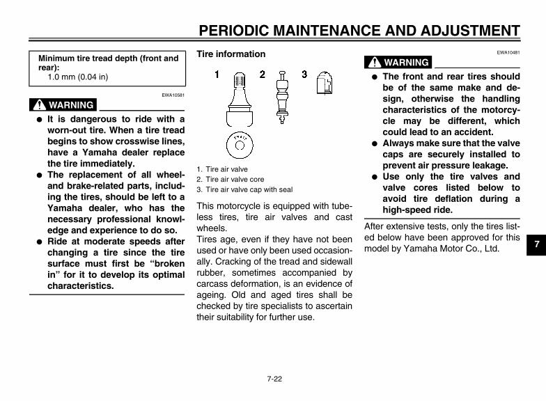
PERIODIC MAINTENANCE AND ADJUSTMENT
7-22
7
WARNINGEWA10581
● It is dangerous to ride with aworn-out tire. When a tire treadbegins to show crosswise lines,have a Yamaha dealer replacethe tire immediately.
● The replacement of all wheel-and brake-related parts, includ-ing the tires, should be left to aYamaha dealer, who has thenecessary professional knowl-edge and experience to do so.
● Ride at moderate speeds afterchanging a tire since the tiresurface must first be “brokenin” for it to develop its optimalcharacteristics.
Tire information
This motorcycle is equipped with tube-less tires, tire air valves and castwheels.Tires age, even if they have not beenused or have only been used occasion-ally. Cracking of the tread and sidewallrubber, sometimes accompanied bycarcass deformation, is an evidence ofageing. Old and aged tires shall bechecked by tire specialists to ascertaintheir suitability for further use.
WARNINGEWA10481
● The front and rear tires shouldbe of the same make and de-sign, otherwise the handlingcharacteristics of the motorcy-cle may be different, whichcould lead to an accident.
● Always make sure that the valvecaps are securely installed toprevent air pressure leakage.
● Use only the tire valves andvalve cores listed below toavoid tire deflation during ahigh-speed ride.
After extensive tests, only the tires list-ed below have been approved for thismodel by Yamaha Motor Co., Ltd.
Minimum tire tread depth (front and rear):
1.0 mm (0.04 in)
1. Tire air valve2. Tire air valve core3. Tire air valve cap with seal
U1MC10E0.book Page 22 Monday, July 30, 2012 4:56 PM

PERIODIC MAINTENANCE AND ADJUSTMENT
7-23
7
WARNINGEWA10600
This motorcycle is fitted with super-high-speed tires. Note the followingpoints in order to make the most ef-ficient use of these tires.
● Use only the specified replace-ment tires. Other tires may runthe danger of bursting at superhigh speeds.
● Brand-new tires can have a rela-tively poor grip on certain roadsurfaces until they have been“broken in”. Therefore, it is ad-visable before doing any high-
speed riding to ride conserva-tively for approximately 100 km(60 mi) after installing a new tire.
● The tires must be warmed upbefore a high-speed run.
● Always adjust the tire air pres-sure according to the operatingconditions.
EAU21962
Cast wheels To maximize the performance, durabil-ity, and safe operation of your vehicle,note the following points regarding thespecified wheels.
● The wheel rims should be checkedfor cracks, bends, warpage or oth-er damage before each ride. If anydamage is found, have a Yamahadealer replace the wheel. Do notattempt even the smallest repair tothe wheel. A deformed or crackedwheel must be replaced.
● The wheel should be balancedwhenever either the tire or wheelhas been changed or replaced. Anunbalanced wheel can result inpoor performance, adverse han-dling characteristics, and a short-ened tire life.
Front tire:Size:
120/70 ZR17M/C (58W)Manufacturer/model:
BRIDGESTONE/BT023F FRear tire:
Size:180/55 ZR17M/C (73W)
Manufacturer/model:BRIDGESTONE/BT023R F
FRONT and REAR:Tire air valve:
TR412Valve core:
#9100 (original)
U1MC10E0.book Page 23 Monday, July 30, 2012 4:56 PM

PERIODIC MAINTENANCE AND ADJUSTMENT
7-24
7
EAU22073
Clutch lever Since this model is equipped with a hy-draulic clutch, adjusting the clutch leverfree play is not needed. However, it isnecessary to check the clutch fluid leveland check the hydraulic system forleakage before each ride. (See page7-26.) If the clutch lever free play doesbecome excessive, and shifting be-comes rough or clutch slippage occurs,causing poor acceleration, there maybe air in the clutch system. If there is airin the hydraulic system, have aYamaha dealer bleed the system be-fore operating the motorcycle.
EAU37913
Checking the brake lever free play
There should be no free play at thebrake lever end. If there is free play,have a Yamaha dealer inspect thebrake system.
WARNINGEWA14211
A soft or spongy feeling in the brakelever can indicate the presence of airin the hydraulic system. If there is airin the hydraulic system, have aYamaha dealer bleed the system be-fore operating the vehicle. Air in thehydraulic system will diminish the
braking performance, which may re-sult in loss of control and an acci-dent.
1. No brake lever free play
1
U1MC10E0.book Page 24 Monday, July 30, 2012 4:56 PM

PERIODIC MAINTENANCE AND ADJUSTMENT
7-25
7
EAU22282
Brake light switches The brake light, which is activated bythe brake pedal and brake lever, shouldcome on just before braking takes ef-fect. Since the brake light switches arecomponents of the cruise control sys-tem, they must be adjusted by aYamaha dealer, who has the neces-sary professional knowledge and expe-rience.
EAU22392
Checking the front and rear brake pads The front and rear brake pads must bechecked for wear at the intervals spec-ified in the periodic maintenance andlubrication chart.
EAU43431
Front brake pads
The front brake calipers are equippedwith two sets of brake pads.Each front brake pad is provided with awear indicator groove, which allowsyou to check the brake pad wear with-out having to disassemble the brake.To check a brake pad for wear, checkits wear indicator groove. If a brake padhas worn to the point that the wear indi-
cator groove has almost disappeared,have a Yamaha dealer replace thebrake pads as a set.
EAU22500
Rear brake pads
Check each rear brake pad for damageand measure the lining thickness. If abrake pad is damaged or if the liningthickness is less than 0.8 mm (0.03 in),have a Yamaha dealer replace thebrake pads as a set.
1. Brake pad wear indicator groove
11
1. Lining thickness
1
U1MC10E0.book Page 25 Monday, July 30, 2012 4:56 PM

PERIODIC MAINTENANCE AND ADJUSTMENT
7-26
7
EAU40271
Checking the brake and clutch fluid levels Before riding, check that the brake andclutch fluids are above the minimumlevel marks. Check the brake andclutch fluid levels with the tops of thereservoirs level. Replenish the brakeand clutch fluids if necessary.
Front brake
Rear brake
Clutch
TIPThe rear brake fluid reservoir is locatedbehind panel C. (See page 7-9.)
WARNINGEWA16030
Improper maintenance can result inloss of braking ability or clutch oper-ation. Observe these precautions:
● Insufficient brake or clutch fluidmay allow air to enter the brakeor clutch system, reducingbraking or clutch performance.
● Clean the filler caps before re-moving. Use only DOT 4 brakefluid from a sealed container.
● Use only the specified brake flu-id; otherwise, the rubber sealsmay deteriorate, causing leak-age.
● Refill with the same type ofbrake fluid. Adding a brake fluidother than DOT 4 may result in aharmful chemical reaction.
● Be careful that water or dustdoes not enter the brake orclutch fluid reservoir when refill-ing. Water will significantly low-er the boiling point of the fluid
1. Minimum level mark
1. Minimum level mark
1. Minimum level mark
Specified brake and clutch fluid:DOT 4 brake fluid
U1MC10E0.book Page 26 Monday, July 30, 2012 4:56 PM

PERIODIC MAINTENANCE AND ADJUSTMENT
7-27
7
and may result in vapor lock,and dirt may clog the ABS hy-draulic unit valves.
NOTICEECA17640
Brake fluid may damage painted sur-faces or plastic parts. Always cleanup spilled fluid immediately.
The brake or clutch fluid reservoir dia-phragm will lose its shape from the neg-ative pressure if the fluid level goesdown too far. Be sure to return the dia-phragm to its original shape before in-stalling it into the brake or clutch fluidreservoir.As the brake pads wear, it is normal forthe brake fluid level to gradually godown. A low brake fluid level may indi-cate worn brake pads and/or brake sys-tem leakage; therefore, be sure tocheck the brake pads for wear and thebrake system for leakage. A low clutchfluid level may indicate clutch systemleakage; therefore, be sure to check theclutch system for leakage. If the brakeor clutch fluid level goes down sudden-ly, have a Yamaha dealer check thecause before further riding.
EAU22752
Changing the brake and clutch fluids Have a Yamaha dealer change thebrake and clutch fluids at the intervalsspecified in the periodic maintenanceand lubrication chart or in the TIP afterthe periodic maintenance and lubrica-tion chart. In addition, have the oil sealsof the brake and clutch master cylin-ders and calipers as well as the brakeand clutch hoses replaced at the inter-vals listed below or whenever they aredamaged or leaking.
● Oil seals: Replace every twoyears.
● Brake and clutch hoses: Replaceevery four years.
EAU23095
Checking and lubricating the cables The operation of all control cables andthe condition of the cables should bechecked before each ride, and the ca-bles and cable ends should be lubricat-ed if necessary. If a cable is damagedor does not move smoothly, have aYamaha dealer check or replace it.WARNING! Damage to the outerhousing of cables may result in in-ternal rusting and cause interfer-ence with cable movement. Replacedamaged cables as soon as possi-ble to prevent unsafe conditions.[EWA10711]
Recommended lubricant:Yamaha Chain and Cable Lube or engine oil
U1MC10E0.book Page 27 Monday, July 30, 2012 4:56 PM

PERIODIC MAINTENANCE AND ADJUSTMENT
7-28
7
EAU23114
Checking and lubricating the throttle grip and cable The operation of the throttle grip shouldbe checked before each ride. In addi-tion, the cable should be lubricated by aYamaha dealer at the intervals speci-fied in the periodic maintenance chart.The throttle cable is equipped with arubber cover. Make sure that the coveris securely installed. Even though thecover is installed correctly, it does notcompletely protect the cable from waterentry. Therefore, use care not to pourwater directly onto the cover or cablewhen washing the vehicle. If the cableor cover becomes dirty, wipe clean witha moist cloth.
EAU44273
Checking and lubricating the brake and shift pedals The operation of the brake and shiftpedals should be checked before eachride, and the pedal pivots should be lu-bricated if necessary.
Brake pedal
Shift pedal
Recommended lubricant:Lithium-soap-based grease
U1MC10E0.book Page 28 Monday, July 30, 2012 4:56 PM

PERIODIC MAINTENANCE AND ADJUSTMENT
7-29
7
EAU43601
Checking and lubricating the brake and clutch levers The operation of the brake and clutchlevers should be checked before eachride, and the lever pivots should be lu-bricated if necessary.
Brake lever
Clutch lever
EAU23213
Checking and lubricating the centerstand and sidestand
The operation of the centerstand andsidestand should be checked beforeeach ride, and the pivots and metal-to-metal contact surfaces should be lubri-cated if necessary.
WARNINGEWA10741
If the centerstand or sidestand doesnot move up and down smoothly,have a Yamaha dealer check or re-pair it. Otherwise, the centerstand orsidestand could contact the groundand distract the operator, resultingin a possible loss of control.
Recommended lubricant:Silicone grease
U1MC10E0.book Page 29 Monday, July 30, 2012 4:56 PM

PERIODIC MAINTENANCE AND ADJUSTMENT
7-30
7
EAU23251
Lubricating the rear suspen-sion
The pivoting points of the rear suspen-sion must be lubricated by a Yamahadealer at the intervals specified in theperiodic maintenance and lubricationchart.
EAUM1652
Lubricating the swingarm piv-ots
The swingarm pivots must be lubricat-ed by a Yamaha dealer at the intervalsspecified in the periodic maintenanceand lubrication chart.
Recommended lubricant:Lithium-soap-based grease
Recommended lubricant:Lithium-soap-based grease
Recommended lubricant:Lithium-soap-based grease
U1MC10E0.book Page 30 Monday, July 30, 2012 4:56 PM

PERIODIC MAINTENANCE AND ADJUSTMENT
7-31
7
EAU23272
Checking the front fork The condition and operation of the frontfork must be checked as follows at theintervals specified in the periodic main-tenance and lubrication chart.
To check the conditionCheck the inner tubes for scratches,damage and excessive oil leakage.
To check the operation1. Place the vehicle on a level sur-
face and hold it in an upright posi-tion. WARNING! To avoid injury,securely support the vehicle sothere is no danger of it fallingover. [EWA10751]
2. While applying the front brake,push down hard on the handlebarsseveral times to check if the frontfork compresses and reboundssmoothly.
NOTICEECA10590
If any damage is found or the frontfork does not operate smoothly,have a Yamaha dealer check or re-pair it.
EAU45511
Checking the steering Worn or loose steering bearings maycause danger. Therefore, the operationof the steering must be checked as fol-lows at the intervals specified in the pe-riodic maintenance and lubricationchart.
1. Place the vehicle on the center-stand. WARNING! To avoid inju-ry, securely support the vehicleso there is no danger of it fallingover. [EWA10751]
2. Hold the lower ends of the frontfork legs and try to move them for-ward and backward. If any freeplay can be felt, have a Yamahadealer check or repair the steering.
U1MC10E0.book Page 31 Monday, July 30, 2012 4:56 PM

PERIODIC MAINTENANCE AND ADJUSTMENT
7-32
7
EAU23291
Checking the wheel bearings
The front and rear wheel bearings mustbe checked at the intervals specified inthe periodic maintenance and lubrica-tion chart. If there is play in the wheelhub or if the wheel does not turnsmoothly, have a Yamaha dealer checkthe wheel bearings.
EAU39525
Battery
The battery is located under panel A.(See page 7-9.)This model is equipped with a VRLA(Valve Regulated Lead Acid) battery.There is no need to check the electro-lyte or to add distilled water. However,the battery lead connections need to bechecked and, if necessary, tightened.
WARNINGEWA10760
● Electrolyte is poisonous anddangerous since it contains sul-furic acid, which causes severeburns. Avoid any contact with
skin, eyes or clothing and al-ways shield your eyes whenworking near batteries. In caseof contact, administer the fol-lowing FIRST AID.• EXTERNAL: Flush with plenty
of water.• INTERNAL: Drink large quan-
tities of water or milk and im-mediately call a physician.
• EYES: Flush with water for 15minutes and seek promptmedical attention.
● Batteries produce explosive hy-drogen gas. Therefore, keepsparks, flames, cigarettes, etc.,away from the battery and pro-vide sufficient ventilation whencharging it in an enclosedspace.
● KEEP THIS AND ALL BATTER-IES OUT OF THE REACH OFCHILDREN.
To charge the batteryHave a Yamaha dealer charge the bat-tery as soon as possible if it seems tohave discharged. Keep in mind that the
1. Battery2. Positive battery lead (red)3. Negative battery lead (black)
1
2
3
U1MC10E0.book Page 32 Monday, July 30, 2012 4:56 PM

PERIODIC MAINTENANCE AND ADJUSTMENT
7-33
7
battery tends to discharge more quicklyif the vehicle is equipped with optionalelectrical accessories.
NOTICEECA16521
To charge a VRLA (Valve RegulatedLead Acid) battery, a special (con-stant-voltage) battery charger is re-quired. Using a conventional batterycharger will damage the battery.
To store the battery1. If the vehicle will not be used for
more than one month, remove thebattery, fully charge it, and thenplace it in a cool, dry place.NOTICE: When removing thebattery, be sure the key isturned to “OFF”, then discon-nect the negative lead beforedisconnecting the positive lead.[ECA16302]
2. If the battery will be stored for morethan two months, check it at leastonce a month and fully charge it ifnecessary.
3. Fully charge the battery before in-stallation. NOTICE: When install-ing the battery, be sure the key
is turned to “OFF”, then con-nect the positive lead beforeconnecting the negative lead.[ECA16840]
4. After installation, make sure thatthe battery leads are properly con-nected to the battery terminals.
NOTICEECA16530
Always keep the battery charged.Storing a discharged battery cancause permanent battery damage.
EAU54510
Replacing the fuses The fuse boxes and individual fuses arelocated under panel A. (See page 7-9.)
1. Main fuse 12. Spare fuse3. Cruise control fuse4. Brake light fuse5. Fuse box6. Main fuse 2
5
134 2
2
5
26
U1MC10E0.book Page 33 Monday, July 30, 2012 4:56 PM

PERIODIC MAINTENANCE AND ADJUSTMENT
7-34
7
If a fuse is blown, replace it as follows.1. Turn the key to “OFF” and turn off
the electrical circuit in question.
2. Remove the blown fuse, and theninstall a new fuse of the specifiedamperage. WARNING! Do notuse a fuse of a higher amperagerating than recommended toavoid causing extensive dam-age to the electrical system andpossibly a fire. [EWA15131]
1. ABS motor fuse2. ABS solenoid fuse3. Fuel injection system fuse4. Backup fuse (for clock and immobilizer sys-
tem)5. Electronic throttle valve fuse6. Headlight fuse7. Spare fuse8. Hazard fuse9. Signaling system fuse10.Auxiliary DC jack fuse11.ABS control unit fuse12.Ignition fuse13.Right radiator fan fuse14.Left radiator fan fuse15.Windshield motor fuse
147
9101112 13
7
158
1
7
2 3456
7
Specified fuses:Main fuse 1:
50.0 AMain fuse 2:
30.0 AHeadlight fuse:
25.0 ABrake light fuse:
1.0 ASignaling system fuse:
10.0 AIgnition fuse:
20.0 ARadiator fan fuse:
10.0 A × 2Backup fuse:
7.5 AHazard fuse:
7.5 AFuel injection system fuse:
15.0 AABS control unit fuse:
7.5 AABS motor fuse:
30.0 AABS solenoid fuse:
20.0 ACruise control fuse:
1.0 AAuxiliary DC jack fuse:
3.0 AWindshield motor fuse:
20.0 AElectronic throttle valve fuse:
7.5 A
U1MC10E0.book Page 34 Monday, July 30, 2012 4:56 PM

PERIODIC MAINTENANCE AND ADJUSTMENT
7-35
7
3. Turn the key to “ON” and turn onthe electrical circuit in question tocheck if the device operates.
4. If the fuse immediately blowsagain, have a Yamaha dealercheck the electrical system.
EAU40361
Headlight bulb If a headlight does not come on, have aYamaha dealer check its electrical cir-cuit or replace the bulb.
NOTICEECA16580
Do not affix any type of tinted film orstickers to the headlight lens.
EAU54770
Front turn signal/position light This model is equipped with LED-typefront turn signal/position lights.If a front turn signal/position light doesnot come on, have a Yamaha dealercheck it.
U1MC10E0.book Page 35 Monday, July 30, 2012 4:56 PM
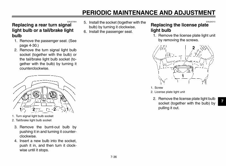
PERIODIC MAINTENANCE AND ADJUSTMENT
7-36
7
EAU27004
Replacing a rear turn signal light bulb or a tail/brake light bulb
1. Remove the passenger seat. (Seepage 4-30.)
2. Remove the turn signal light bulbsocket (together with the bulb) orthe tail/brake light bulb socket (to-gether with the bulb) by turning itcounterclockwise.
3. Remove the burnt-out bulb bypushing it in and turning it counter-clockwise.
4. Insert a new bulb into the socket,push it in, and then turn it clock-wise until it stops.
5. Install the socket (together with thebulb) by turning it clockwise.
6. Install the passenger seat.
EAU24313
Replacing the license plate light bulb
1. Remove the license plate light unitby removing the screws.
2. Remove the license plate light bulbsocket (together with the bulb) bypulling it out.
1. Turn signal light bulb socket2. Tail/brake light bulb socket
1. Screw2. License plate light unit
U1MC10E0.book Page 36 Monday, July 30, 2012 4:56 PM

PERIODIC MAINTENANCE AND ADJUSTMENT
7-37
7
3. Remove the burnt-out bulb by pull-ing it out.
4. Insert a new bulb into the socket.5. Install the socket (together with the
bulb) by pushing it in.6. Install the license plate light unit by
installing the screws.
EAU54500
Auxiliary light
This model is equipped with LED-typeauxiliary lights.If an auxiliary light does not come on,have a Yamaha dealer check it.
EAU25871
Troubleshooting Although Yamaha motorcycles receivea thorough inspection before shipmentfrom the factory, trouble may occur dur-ing operation. Any problem in the fuel,compression, or ignition systems, forexample, can cause poor starting andloss of power.The following troubleshooting chartsrepresent quick and easy proceduresfor checking these vital systems your-self. However, should your motorcyclerequire any repair, take it to a Yamahadealer, whose skilled technicians havethe necessary tools, experience, andknow-how to service the motorcycleproperly.Use only genuine Yamaha replace-ment parts. Imitation parts may look likeYamaha parts, but they are often inferi-or, have a shorter service life and canlead to expensive repair bills.
WARNINGEWA15141
When checking the fuel system, donot smoke, and make sure there areno open flames or sparks in the ar-ea, including pilot lights from water
1. License plate light bulb2. License plate light bulb socket
12
1. Auxiliary light
1 1
U1MC10E0.book Page 37 Monday, July 30, 2012 4:56 PM
PERIODIC MAINTENANCE AND ADJUSTMENT
7-38
7
heaters or furnaces. Gasoline orgasoline vapors can ignite or ex-plode, causing severe injury orproperty damage.
U1MC10E0.book Page 38 Monday, July 30, 2012 4:56 PM

PERIODIC MAINTENANCE AND ADJUSTMENT
7-39
7
EAU42504
Troubleshooting charts
Starting problems or poor engine performance
Check the fuel level inthe fuel tank.
1. FuelThere is enough fuel.
There is no fuel.
Check the battery.
Supply fuel. The engine does not start. Check the battery.
Remove the spark plugsand check the electrodes.
3. Ignition Wipe off with a dry cloth and correct thespark plug gaps, or replace the spark plugs.
Have a Yamaha dealer check the vehicle.
Operate the electric starter.
4. CompressionThere is compression.
There is no compression.
The engine does not start. Have a Yamaha dealer check the vehicle.
Have a Yamaha dealer check the vehicle.
The engine does not start.Check the compression.
Operate the electric starter.
2. Battery The engine turns over quickly.
The engine turns over slowly.
The engine does not start.Check the ignition.
The battery is good.
Check the battery lead connections,and have a Yamaha dealer charge the battery if necessary.
Dry
Wet Operate the electric starter.
U1MC10E0.book Page 39 Monday, July 30, 2012 4:56 PM

PERIODIC MAINTENANCE AND ADJUSTMENT
7-40
7
Engine overheating
WARNINGEWAT1040
● Do not remove the radiator cap when the engine and radiator are hot. Scalding hot fluid and steam may beblown out under pressure, which could cause serious injury. Be sure to wait until the engine has cooled.
● Place a thick rag, like a towel, over the radiator cap, and then slowly rotate the cap counterclockwise to the de-tent to allow any residual pressure to escape. When the hissing sound has stopped, press down on the capwhile turning it counterclockwise, and then remove the cap.
TIPIf coolant is not available, tap water can be temporarily used instead, provided that it is changed to the recommended coolantas soon as possible.
Wait until the engine has cooled.
Check the coolant level in the reservoir and radiator.
The coolant level is OK.
The coolant level is low.Check the cooling systemfor leakage.
Have a Yamaha dealer checkand repair the cooling system.
Add coolant. (See TIP.)
Start the engine. If the engine overheats again, have a Yamaha dealer check and repair the cooling system.
There isleakage.
There is no leakage.
U1MC10E0.book Page 40 Monday, July 30, 2012 4:56 PM

MOTORCYCLE CARE AND STORAGE
8-1
8
EAU37833
Matte color caution
NOTICEECA15192
Some models are equipped withmatte colored finished parts. Besure to consult a Yamaha dealer foradvice on what products to use be-fore cleaning the vehicle. Using abrush, harsh chemical products orcleaning compounds when cleaningthese parts will scratch or damagetheir surface. Wax also should notbe applied to any matte colored fin-ished parts.
EAU54670
Care While the open design of a motorcyclereveals the attractiveness of the tech-nology, it also makes it more vulnera-ble. Rust and corrosion can developeven if high-quality components areused. A rusty exhaust pipe may go un-noticed on a car, however, it detractsfrom the overall appearance of a motor-cycle. Frequent and proper care doesnot only comply with the terms of thewarranty, but it will also keep your mo-torcycle looking good, extend its lifeand optimize its performance.
Before cleaning1. Cover the muffler outlets with plas-
tic bags after the engine hascooled down.
2. Make sure that all caps and coversas well as all electrical couplersand connectors, including thespark plug caps, are tightly in-stalled.
3. Remove extremely stubborn dirt,like oil burnt onto the crankcase,with a degreasing agent and abrush, but never apply such prod-
ucts onto seals, gaskets and wheelaxles. Always rinse the dirt and de-greaser off with water.
Cleaning
NOTICEECA10772
● Avoid using strong acidic wheelcleaners, especially on spokedwheels. If such products areused on hard-to-remove dirt, donot leave the cleaner on the af-fected area any longer than in-structed. Also, thoroughly rinsethe area off with water, immedi-ately dry it, and then apply a cor-rosion protection spray.
● Improper cleaning can damageplastic parts (such as cowlings,panels, windshields, headlightlenses, meter lenses, etc.) andthe mufflers. Use only a soft,clean cloth or sponge with wa-ter to clean plastic. However, ifthe plastic parts cannot be thor-oughly cleaned with water, di-luted mild detergent with watermay be used. Be sure to rinse
U1MC10E0.book Page 1 Monday, July 30, 2012 4:56 PM

MOTORCYCLE CARE AND STORAGE
8-2
8
off any detergent residue usingplenty of water, as it is harmfulto plastic parts.
● Do not use any harsh chemicalproducts on plastic parts. Besure to avoid using cloths orsponges which have been incontact with strong or abrasivecleaning products, solvent orthinner, fuel (gasoline), rust re-movers or inhibitors, brake flu-id, antifreeze or electrolyte.
● Do not use high-pressure wash-ers or steam-jet cleaners sincethey cause water seepage anddeterioration in the following ar-eas: seals (of wheel and swing-arm bearings, fork and brakes),electric components (couplers,connectors, instruments,switches and lights), breatherhoses and vents.
● For motorcycles equipped witha windshield: Do not use strongcleaners or hard sponges asthey will cause dulling orscratching. Some cleaning com-pounds for plastic may leavescratches on the windshield.
Test the product on a small hid-den part of the windshield tomake sure that it does not leaveany marks. If the windshield isscratched, use a quality plasticpolishing compound afterwashing.
After normal useRemove dirt with warm water, a milddetergent, and a soft, clean sponge,and then rinse thoroughly with cleanwater. Use a toothbrush or bottlebrushfor hard-to-reach areas. Stubborn dirtand insects will come off more easily ifthe area is covered with a wet cloth fora few minutes before cleaning.
After riding in the rain, near the sea oron salt-sprayed roadsSince sea salt or salt sprayed on roadsduring winter are extremely corrosive incombination with water, carry out thefollowing steps after each ride in therain, near the sea or on salt-sprayedroads.
TIPSalt sprayed on roads in the winter mayremain well into spring.
1. Clean the motorcycle with cold wa-ter and a mild detergent, after theengine has cooled down.NOTICE: Do not use warm watersince it increases the corrosiveaction of the salt. [ECA10791]
2. After drying the motorcycle, applya corrosion protection spray on allmetal, including chrome- and nick-el-plated, surfaces to prevent cor-rosion.
Windshield cleaningAvoid using any alkaline or strong acidcleaner, gasoline, brake fluid, or anyother solvent. Clean the windshield witha cloth or sponge dampened with aneutral detergent, and after cleaning,thoroughly wash it off with water. Foradditional cleaning, use Yamaha Wind-shield Cleaner or other quality cleaner.Some cleaning compounds for plasticsmay leave scratches on surfaces of the
U1MC10E0.book Page 2 Monday, July 30, 2012 4:56 PM

MOTORCYCLE CARE AND STORAGE
8-3
8
windshield. Before using them, make atest by polishing an area which doesnot affect your visibility.
After cleaning1. Dry the motorcycle with a chamois
or an absorbing cloth.2. Use a chrome polish to shine
chrome, aluminum and stainless-steel parts, including the exhaustsystem. (Even the thermally in-duced discoloring of stainless-steel exhaust systems can be re-moved through polishing.)
3. To prevent corrosion, it is recom-mended to apply a corrosion pro-tection spray on all metal,including chrome- and nickel-plat-ed, surfaces.
4. Use spray oil as a universal clean-er to remove any remaining dirt.
5. Touch up minor paint damagecaused by stones, etc.
6. Wax all painted surfaces.7. Let the motorcycle dry completely
before storing or covering it.
WARNINGEWA11131
Contaminants on the brakes or tirescan cause loss of control.
● Make sure that there is no oil orwax on the brakes or tires.
● If necessary, clean the brakediscs and brake linings with aregular brake disc cleaner or ac-etone, and wash the tires withwarm water and a mild deter-gent. Before riding at higherspeeds, test the motorcycle’sbraking performance and cor-nering behavior.
NOTICEECA10800
● Apply spray oil and wax spar-ingly and make sure to wipe offany excess.
● Never apply oil or wax to anyrubber and plastic parts, buttreat them with a suitable careproduct.
● Avoid using abrasive polishingcompounds as they will wearaway the paint.
TIP● Consult a Yamaha dealer for ad-
vice on what products to use.● Washing, rainy weather or humid
climates can cause the headlightlens to fog. Turning the headlighton for a short period of time willhelp remove the moisture from thelens.
U1MC10E0.book Page 3 Monday, July 30, 2012 4:56 PM

MOTORCYCLE CARE AND STORAGE
8-4
8
EAU26243
Storage
Short-termAlways store your motorcycle in a cool,dry place and, if necessary, protect itagainst dust with a porous cover. Besure the engine and the exhaust sys-tem are cool before covering the motor-cycle.
NOTICEECA10810
● Storing the motorcycle in apoorly ventilated room or cover-ing it with a tarp, while it is stillwet, will allow water and humid-ity to seep in and cause rust.
● To prevent corrosion, avoiddamp cellars, stables (becauseof the presence of ammonia)and areas where strong chemi-cals are stored.
Long-termBefore storing your motorcycle for sev-eral months:
1. Follow all the instructions in the“Care” section of this chapter.
2. Fill up the fuel tank and add fuelstabilizer (if available) to preventthe fuel tank from rusting and thefuel from deteriorating.
3. Perform the following steps to pro-tect the cylinders, piston rings, etc.from corrosion.a. Remove the spark plug caps
and spark plugs.b. Pour a teaspoonful of engine oil
into each spark plug bore.c. Install the spark plug caps onto
the spark plugs, and then placethe spark plugs on the cylinderhead so that the electrodes aregrounded. (This will limit spark-ing during the next step.)
d. Turn the engine over severaltimes with the starter. (This willcoat the cylinder walls with oil.)WARNING! To prevent dam-age or injury from sparking,make sure to ground thespark plug electrodes whileturning the engine over.[EWA10951]
e. Remove the spark plug capsfrom the spark plugs, and theninstall the spark plugs and thespark plug caps.
4. Lubricate all control cables and thepivoting points of all levers andpedals as well as of the side-stand/centerstand.
5. Check and, if necessary, correctthe tire air pressure, and then liftthe motorcycle so that both of itswheels are off the ground. Alterna-tively, turn the wheels a little everymonth in order to prevent the tiresfrom becoming degraded in onespot.
6. Cover the muffler outlets with plas-tic bags to prevent moisture fromentering them.
7. Remove the battery and fullycharge it. Store it in a cool, dryplace and charge it once a month.Do not store the battery in an ex-cessively cold or warm place [lessthan 0 °C (30 °F) or more than 30°C (90 °F)]. For more informationon storing the battery, see page7-32.
U1MC10E0.book Page 4 Monday, July 30, 2012 4:56 PM

MOTORCYCLE CARE AND STORAGE
8-5
8
TIPMake any necessary repairs beforestoring the motorcycle.
U1MC10E0.book Page 5 Monday, July 30, 2012 4:56 PM

SPECIFICATIONS
9-1
9
Dimensions:Overall length:
2230 mm (87.8 in)Overall width:
750 mm (29.5 in)Overall height:
1325/1455 mm (52.2/57.3 in)Seat height:
805/825 mm (31.7/32.5 in)Wheelbase:
1545 mm (60.8 in)Ground clearance:
130 mm (5.12 in)Minimum turning radius:
3100 mm (122.0 in)Weight:
Curb weight:FJR13AD 289 kg (637 lb)FJR13ADC 290 kg (639 lb)
Engine:Engine type:
Liquid cooled 4-stroke, DOHCCylinder arrangement:
Inline 4-cylinderDisplacement:
1298 cm³Bore × stroke:
79.0 × 66.2 mm (3.11 × 2.61 in)Compression ratio:
10.80 : 1Starting system:
Electric starterLubrication system:
Wet sump
Engine oil:Recommended brand:
YAMALUBEType:
SAE 10W-40, 10W-50, 15W-40, 20W-40 or 20W-50
Recommended engine oil grade:API service SG type or higher, JASO standard MA
Engine oil quantity:Without oil filter cartridge replacement:
3.80 L (4.02 US qt, 3.34 Imp.qt)With oil filter cartridge replacement:
4.00 L (4.23 US qt, 3.52 Imp.qt)Final gear oil:
Type:Yamaha genuine shaft drive gear oil SAE 80 API GL-5
Quantity:0.20 L (0.21 US qt, 0.18 Imp.qt)
Cooling system:Coolant reservoir capacity (up to the maximum level mark):
0.25 L (0.26 US qt, 0.22 Imp.qt)Radiator capacity (including all routes):
2.60 L (2.75 US qt, 2.29 Imp.qt)Air filter:
Air filter element:Dry element
Fuel:Recommended fuel:
Unleaded gasoline onlyFuel tank capacity:
25.0 L (6.61 US gal, 5.50 Imp.gal)Fuel reserve amount:
5.5 L (1.45 US gal, 1.21 Imp.gal)Fuel injection:
Throttle body:ID mark:
FJR13AD 1MC1 00FJR13ADC 1MC4 10
Spark plug(s):Manufacturer/model:
NGK/CPR8EA-9Spark plug gap:
0.8–0.9 mm (0.031–0.035 in)Clutch:
Clutch type:Wet, multiple-disc
Transmission:Primary reduction ratio:
1.563 (75/48)Final drive:
Shaft
–20 –10 0 10 20 30 40 50 ˚C
10 30 50 70 90 1100 130 ˚F
SAE 20W-50
SAE 20W-40
SAE 15W-40
SAE 10W-40
SAE 10W-50
U1MC10E0.book Page 1 Monday, July 30, 2012 4:56 PM

SPECIFICATIONS
9-2
9
Secondary reduction ratio:2.698 (35/37 x 21/27 x 33/9)
Transmission type:Constant mesh 5-speed
Operation:Left foot operation
Gear ratio:1st:
2.529 (43/17)2nd:
1.773 (39/22)3rd:
1.348 (31/23)4th:
1.077 (28/26)5th:
0.929 (26/28)Chassis:
Frame type:Diamond
Caster angle:26.00 °
Trail:109 mm (4.3 in)
Front tire:Type:
TubelessSize:
120/70 ZR17M/C (58W)Manufacturer/model:
BRIDGESTONE/BT023F FRear tire:
Type:Tubeless
Size:180/55 ZR17M/C (73W)
Manufacturer/model:BRIDGESTONE/BT023R F
Loading:Maximum load:
FJR13AD 215 kg (474 lb)FJR13ADC 214 kg (472 lb)(Total weight of rider, passenger, cargo and accessories)
Tire air pressure (measured on cold tires):
Loading condition:0–90 kg (0–198 lb)Front:
250 kPa (2.50 kgf/cm², 36 psi)Rear:
290 kPa (2.90 kgf/cm², 42 psi)Loading condition:
FJR13AD 90–215 kg (198–474 lb)FJR13ADC 90–214 kg (198–472 lb)Front:
250 kPa (2.50 kgf/cm², 36 psi)Rear:
290 kPa (2.90 kgf/cm², 42 psi)High-speed riding:
Front:250 kPa (2.50 kgf/cm², 36 psi)
Rear:290 kPa (2.90 kgf/cm², 42 psi)
Front wheel:Wheel type:
Cast wheel
Rim size:17M/C x MT3.50
Rear wheel:Wheel type:
Cast wheelRim size:
17M/C x MT5.50Unified brake system:
Operation:Activated by rear brake
Front brake:Type:
Dual disc brakeOperation:
Right hand operationSpecified brake fluid:
DOT 4Rear brake:
Type:Single disc brake
Operation:Right foot operation
Specified brake fluid:DOT 4
Front suspension:Type:
Telescopic forkSpring/shock absorber type:
Coil spring/oil damperWheel travel:
135.0 mm (5.31 in)Rear suspension:
Type:Swingarm (link suspension)
U1MC10E0.book Page 2 Monday, July 30, 2012 4:56 PM

SPECIFICATIONS
9-3
9
Spring/shock absorber type:Coil spring/gas-oil damper
Wheel travel:125.0 mm (4.92 in)
Electrical system:Ignition system:
TCICharging system:
AC magnetoBattery:
Model:GT14B-4
Voltage, capacity:12 V, 12.0 Ah
Headlight:Bulb type:
Halogen bulbBulb voltage, wattage × quantity:
Headlight:12 V, 60.0 W/55.0 W × 2
Tail/brake light:12 V, 5.0 W/21.0 W × 2
Front turn signal/position light:LED
Rear turn signal light:12 V, 21.0 W × 2
Auxiliary light:LED
License plate light:12 V, 5.0 W × 1
Meter lighting:LED
Neutral indicator light:LED
High beam indicator light:LED
Oil level warning light:LED
Turn signal indicator light:LED
Engine trouble warning light:LED
ABS warning light:LED
Cruise control “SET” indicator light:LED
Cruise control “ON” indicator light:LED
Traction control system indicator/warning light:
LEDFuses:
Main fuse 1:50.0 A
Main fuse 2:30.0 A
Headlight fuse:25.0 A
Brake light fuse:1.0 A
Signaling system fuse:10.0 A
Ignition fuse:20.0 A
Radiator fan fuse:10.0 A × 2
Hazard fuse:7.5 A
Fuel injection system fuse:15.0 A
ABS control unit fuse:7.5 A
ABS motor fuse:30.0 A
ABS solenoid fuse:20.0 A
Cruise control fuse:1.0 A
Auxiliary DC jack fuse:3.0 A
Backup fuse:7.5 A
Windshield motor fuse:20.0 A
Electronic throttle valve fuse:7.5 A
U1MC10E0.book Page 3 Monday, July 30, 2012 4:56 PM

CONSUMER INFORMATION
10-1
10
EAU26353
Identification numbers Record the key identification number,vehicle identification number and mod-el label information in the spaces pro-vided below for assistance whenordering spare parts from a Yamahadealer or for reference in case the vehi-cle is stolen.
KEY IDENTIFICATION NUMBER:
VEHICLE IDENTIFICATION NUMBER:
MODEL LABEL INFORMATION:
EAU26381
Key identification number
The key identification number isstamped into the key tag. Record thisnumber in the space provided and useit for reference when ordering a newkey.
EAU26400
Vehicle identification number
The vehicle identification number isstamped into the steering head pipe.Record this number in the space pro-vided.
TIPThe vehicle identification number isused to identify your motorcycle andmay be used to register your motorcy-cle with the licensing authority in yourarea.
1. Key identification number 1. Vehicle identification number
1
U1MC10E0.book Page 1 Monday, July 30, 2012 4:56 PM
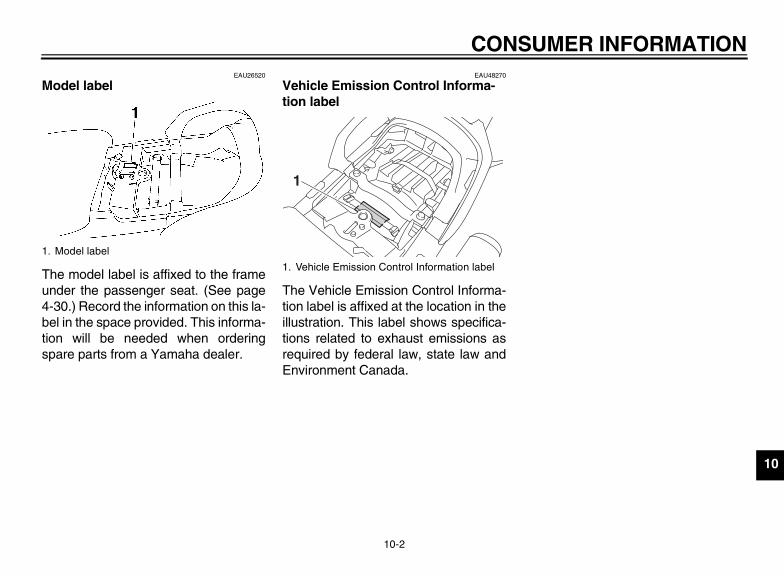
CONSUMER INFORMATION
10-2
10
EAU26520
Model label
The model label is affixed to the frameunder the passenger seat. (See page4-30.) Record the information on this la-bel in the space provided. This informa-tion will be needed when orderingspare parts from a Yamaha dealer.
EAU48270
Vehicle Emission Control Informa-tion label
The Vehicle Emission Control Informa-tion label is affixed at the location in theillustration. This label shows specifica-tions related to exhaust emissions asrequired by federal law, state law andEnvironment Canada.
1. Model label
1. Vehicle Emission Control Information label
1
U1MC10E0.book Page 2 Monday, July 30, 2012 4:56 PM

CONSUMER INFORMATION
10-3
10
EAU26551
Reporting safety defects If you believe that your vehicle has a defect which could cause a crash or could cause injury or death, you should immediatelyinform the National Highway Traffic Safety Administration (NHTSA) in addition to notifying Yamaha Motor Corporation,U.S.A. If NHTSA receives similar complaints, it may open an investigation, and if it finds that a safety defect exists in a groupof vehicles, it may order a recall and remedy campaign. However, NHTSA cannot become involved in individual problemsbetween you, your dealer, or Yamaha Motor Corporation, U.S.A.To contact NHTSA, you may call the Vehicle Safety Hotline toll-free at 1-888-327-4236 (TTY: 1-800-424-9153); go tohttp://www.safercar.gov; or write to: Administrator, NHTSA, 400 Seventh Street, SW., Washington, DC 20590. You can alsoobtain other information about motor vehicle safety from http://www.safercar.gov.
U1MC10E0.book Page 3 Monday, July 30, 2012 4:56 PM
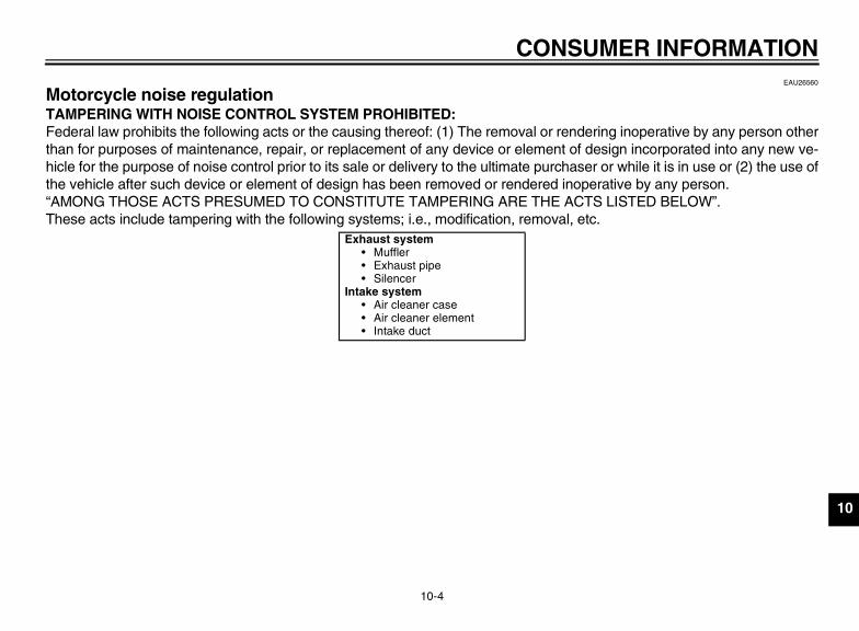
CONSUMER INFORMATION
10-4
10
EAU26560
Motorcycle noise regulation TAMPERING WITH NOISE CONTROL SYSTEM PROHIBITED:Federal law prohibits the following acts or the causing thereof: (1) The removal or rendering inoperative by any person otherthan for purposes of maintenance, repair, or replacement of any device or element of design incorporated into any new ve-hicle for the purpose of noise control prior to its sale or delivery to the ultimate purchaser or while it is in use or (2) the use ofthe vehicle after such device or element of design has been removed or rendered inoperative by any person.“AMONG THOSE ACTS PRESUMED TO CONSTITUTE TAMPERING ARE THE ACTS LISTED BELOW”.These acts include tampering with the following systems; i.e., modification, removal, etc.
Exhaust system• Muffler• Exhaust pipe• Silencer
Intake system• Air cleaner case• Air cleaner element• Intake duct
U1MC10E0.book Page 4 Monday, July 30, 2012 4:56 PM
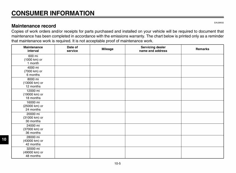
CONSUMER INFORMATION
10-5
10
EAU26632
Maintenance record Copies of work orders and/or receipts for parts purchased and installed on your vehicle will be required to document thatmaintenance has been completed in accordance with the emissions warranty. The chart below is printed only as a reminderthat maintenance work is required. It is not acceptable proof of maintenance work.
Maintenanceinterval
Date ofservice Mileage Servicing dealer
name and address Remarks
600 mi(1000 km) or
1 month4000 mi
(7000 km) or6 months8000 mi
(13000 km) or12 months12000 mi
(19000 km) or18 months16000 mi
(25000 km) or24 months20000 mi
(31000 km) or30 months24000 mi
(37000 km) or36 months28000 mi
(43000 km) or42 months32000 mi
(49000 km) or48 months
U1MC10E0.book Page 5 Monday, July 30, 2012 4:56 PM

CONSUMER INFORMATION
10-6
10
36000 mi(55000 km) or
54 months40000 mi
(61000 km) or60 months
Maintenanceinterval
Date ofservice Mileage Servicing dealer
name and address Remarks
U1MC10E0.book Page 6 Monday, July 30, 2012 4:56 PM

CONSUMER INFORMATION
10-7
10
EAU26663
YAMAHA MOTOR CORPORATION, U.S.A. STREET AND ENDURO MOTORCYCLE LIMITED WARRANTY
a)b)
c)d)e)f)
1.
2.
Yamaha Motor Corporation, U.S.A. hereby warrants that new Yamaha motorcycles will be free from defects in material and workmanship for the period of time stated herein, subject to certain stated limitations.
THE PERIOD OF WARRANTY for Yamaha motorcycles originally equipped with headlight, stoplight, and turn signals shall be one (1) year from the date of purchase, with no mileage limitation.
MODELS EXCLUDED FROM WARRANTY include those used for non-Yamaha-authorized renting, leasing or other commercial purposes, and TZ models.
DURING THE PERIOD OF WARRANTY, any authorized Yamaha motorcycle dealer will, free of charge, repair or replace any part adjudged defective by Yamaha due to faulty workmanship or material from the factory. Parts used in warranty repairs will be warranted for the balance of the product’s warranty period. All parts replaced under warranty become property of Yamaha Motor Corporation, U.S.A.
GENERAL EXCLUSIONS from this warranty shall include any failures caused by:
Competition or racing use.Installation of parts or accessories that are not qualitatively equivalent to genuine Yamaha parts.Abnormal strain, neglect, or abuse.Lack of proper maintenance.Accident or collision damage.Modification to original parts.
SPECIFIC EXCLUSIONS from this warranty shall include parts replaced due to normal wear or routine maintenance.
THE CUSTOMER’S RESPONSIBILITY under this warranty shall be to:
Operate and maintain the motorcycle as specified in the appropriate Owner’s Manual, andGive notice to an authorized Yamaha motorcycle dealer of any and all apparent defects within ten (10) days after discovery, and make the machine available at that time for inspection and repairs at such dealer’s place of business.
WARRANTY TRANSFER: To transfer the warranty from the original purchaser to any subsequent purchaser, it is imperative that the machine be inspected and registered for warranty by an authorized Yamaha motorcycle dealer. In order for this warranty to remain in effect, this inspection and registration must take place within ten (10) days after transfer. An inspection and registration fee will be charged for this service.
EMISSION CONTROL SYSTEM WARRANTY:Yamaha Motor Corporation, U.S.A. also warrants to the ultimate purchaser and each subsequent purchaser of each Yamaha motorcycle covered by this warranty with a displacement of 50cc or greater, that the vehicle is designed, built, and equipped so as to conform at the time of sale with all U.S. emissions standards applicable at the time of manufacture and that it is free from defects in materials and workmanship which would cause it not to meet these standards within the period listed immediately below. Failures other than those resulting from defects in material or workmanship, which arise solely as a result of owner abuse and/or lack of proper maintenance, are not covered by this warranty.
Period6,000 km (3,750 miles)
or five years, whichever occurs first
12,000 km (7,465 miles)or five years whichever occurs first
18,000 km (11,185 miles)or five years, whichever occurs first
30,000 km (18,641 miles)or five years, whichever occurs first
YAMAHA MOTOR CORPORATION, U.S.A. MAKES NO OTHER WARRANTY OF ANY KIND, EXPRESSED OR IMPLIED. ALL IMPLIED WARRANTIES OF MERCHANTABILITY AND FITNESS FOR A PARTICULAR PURPOSE WHICH EXCEED THE OBLIGATIONS AND TIME LIMITS STATED IN THIS WARRANTY ARE HEREBY DISCLAIMED BY YAMAHA MOTOR CORPORATION, U.S.A. AND EXCLUDED FROM THIS WARRANTY.
SOME STATES DO NOT ALLOW LIMITATIONS ON HOW LONG AN IMPLIED WARRANTY LASTS, SO THE ABOVE LIMITATION MAY NOT APPLY TO YOU. ALSO EXCLUDED FROM THIS WARRANTY ARE ANY INCIDENTAL OR CONSEQUENTIAL DAMAGES INCLUDING LOSS OF USE. SOME STATES DO NOT ALLOW THE EXCLUSION OR LIMITATION OF INCIDENTAL OR CONSEQUENTIAL DAMAGES, SO THE ABOVE EXCLUSION MAY NOT APPLY TO YOU.
THIS WARRANTY GIVES YOU SPECIFIC LEGAL RIGHTS, AND YOU MAY ALSO HAVE OTHER RIGHTS WHICH VARY FROM STATE TO STATE.
YAMAHA MOTOR CORPORATION, U.S.A.P.O. Box 6555
Cypress, California 90630
Engine Displacement Under 50cc
50cc to 169cc
170cc to 279cc
280cc and over
U1MC10E0.book Page 7 Monday, July 30, 2012 4:56 PM

CONSUMER INFORMATION
10-8
10
WARRANTY QUESTIONS AND ANSWERS
What costs are my responsibility during the warranty period?The customer’s responsibility includes all costs of normal maintenance services, non-warranty repairs, accident and collision damages, and oil, oil filters, air filters, spark plugs, and brake shoes.
What are some examples of “abnormal” strain, neglect, or abuse?These terms are general and overlap each other in areas. Specific examples include: Running the machine out of oil, sustained high rpm, full-throttle, operating the machine with a broken or damaged part which causes another part to fail, damage or failure due to improper or careless transportation and/or tie-down. If you have any specific questions on operation or maintenance, please contact your dealer for advice.
Does the warranty cover incidental costs such as towing or transportation due toa failure?No. The warranty is limited to repair of the machine itself.
May I perform any or all of the recommended maintenance shown in the Owner’s Manual instead of having the dealer do them?Yes, if you are a qualified mechanic and follow the procedures specified in the Owner’s and Service Manual. We do recommend, however, that items requiring special tools or equipment be done by a Yamaha motorcycle dealer.
Will the warranty be void or cancelled if I do not operate or maintain my new motorcycle exactly as specified in the Owner’s Manual?No. The warranty on a new motorcycle cannot be “voided” or “cancelled.” However, if a particular failure is caused by operation or maintenance other than as described in the Owner’s Manual, that failure may not be covered under warranty.
What responsibility does my dealer have under this warranty?Each Yamaha motorcycle dealer is expected to:
Completely set up every new machine before sale.Explain the operation, maintenance, and warranty requirements to your satisfaction at the time of sale, and upon your request at any later date.Each Yamaha motorcycle dealer is held responsible for his setup, service and warranty repair work.
Is the warranty transferable to second owners?Yes. The remainder of the existing warranty can be transferred upon request. The unit has to be inspected and re-registered by an authorized Yamaha motorcycle dealer for the policy to remain effective.
CUSTOMER SERVICE
If your machine requires warranty service, you must take it to any authorized Yamaha motorcycle dealer within the continental United States. Be sure to bring your warranty registration card or other valid proof of the original date of purchase. If a question or problem arises regarding the warranty, first contact the owner of the dealership. Since all warranty matters are handled at the dealer level, this person is in the best position to help you. IF you are still not satisfied and require additional assistance, please write to:
YAMAHA MOTOR CORPORATION, U.S.A.CUSTOMER RELATIONS DEPARTMENT
P.O. Box 6555Cypress, California 90630
When contacting Yamaha Motor Corporation, U.S.A., don’t forget to include any important information such as names, addresses, model, V.I.N. (frame number), dates, and receipts.
CHANGE OF ADDRESS
The federal government requires each manufacturer of a motor vehicle to maintain a complete, up-to-date list of all first purchasers against the possibility of a safety-related defect and recall. This list is compiled from the purchase registrations sent to Yamaha Motor Corporation, U.S.A. by the selling dealer at the time of your purchase.
If you should move after you have purchased your new motorcycle, please advise us of your new address by sending a postcard listing your motorcycle model name, V.I.N. (frame number), dealer number (or dealer’s name) as it is shown on your warranty card, your name and new mailing address. Mail to:
YAMAHA MOTOR CORPORATION, U.S.A.P.O. Box 6555
Cypress, California 90630Attention: Warranty Department
This will ensure that Yamaha Motor Corporation, U.S.A. has an up-to-date registration record in accordance with federal law.
Q.A.
Q.A.
Q.
A.
Q.
A.
Q.
A.
Q.A.
1.2.
3.
Q.A.
U1MC10E0.book Page 8 Monday, July 30, 2012 4:56 PM

CONSUMER INFORMATION
10-9
10
EAU26751
YAMAHA EXTENDED SERVICE (Y.E.S.) Keep your Yamaha protected even after your warranty expires with genuine Yamaha Extended Service (Y.E.S.).
Y.E.S. is designed and administered by Yamaha Motor Corporation to provide maximum owner satisfaction. You get uninterrupted factory-backed coverage for extra peace of mind.
Y.E.S. is flexible. You choose the plan that’s right foryou: 12 months, 24 months, 36 months or, on certain models, even 48 months beyond your warranty period.
Y.E.S. is designed and administered by the same Yamaha people who handle your warranty – and itshows in the comprehensive coverage benefits. There are no mileage limitations. Coverage isn’t limited to “moving parts” or the “drive train” like many other plans. And Y.E.S. covers manufacturing defects just like the warranty. See the sample contract at your Yamahadealer to see how comforting uninterrupted factory-backed protection can be.
You don’t have to pay anything for covered repairs. There’s no deductible to pay, and repairs aren’t“pro-rated.” You don’t have any “out-of-pocket” expenses for covered repairs.
In addition, Travel and Recreation Interruption Protection (TRIP) is included at no extra cost. TRIP gives you up to $250 reimbursement per occurrence for any reasonable expenses you incur because your Yamaha needs covered service: replacement vehicle rental, emergency towing, phone calls, even food and lodging when you are away from home. This superb coverage goes into effect when you purchase Y.E.S., so it applies to any warranty repairs as well as covered repairs during your entire Y.E.S. plan period.
Y.E.S. coverage is honored at any authorized Yamaha dealer nationwide.
Y.E.S. coverage is transferable to a new owner if yousell or trade-in. That can make your Yamaha much more valuable!
This excellent Y.E.S. plan coverage is only available to Yamaha owners like you, and only while your Yamaha is still within the Yamaha Limited Warranty period. So visit your authorized Yamaha dealer to get all the facts. He can show you how easy it is to protect your investment with Yamaha Extended Service.
U1MC10E0.book Page 9 Monday, July 30, 2012 4:56 PM

CONSUMER INFORMATION
10-10
10
We urge you to act now. You’ll get the excellent benefits of TRIP coverage right away, and you’ll rest easy knowing you’ll have strong factory-backed protection even after your Yamaha Limited Warranty expires.
A special note:If visiting your dealer isn’t convenient, contact Yamaha with your Primary ID number (your frame number). We’ll be happy to help you get the Y.E.S. coverage you need.
Yamaha Service MarketingP.O. Box 6555Cypress, CA 906301-(866)-YES-EXTD (1-866-937-3983)
U1MC10E0.book Page 10 Monday, July 30, 2012 4:56 PM

INDEXA
ABS....................................................... 4-24ABS warning light.................................... 4-3Accessory box....................................... 4-35Air filter element, cleaning..................... 7-18Auxiliary DC jack................................... 4-44Auxiliary light......................................... 7-37
BBattery................................................... 7-32Brake and clutch fluid levels,
checking ............................................. 7-26Brake and clutch fluids, changing ......... 7-27Brake and clutch levers, checking and
lubricating ........................................... 7-29Brake and shift pedals, checking and
lubricating ........................................... 7-28Brake lever............................................ 4-24Brake lever free play, checking............. 7-24Brake light switches .............................. 7-25Brake pedal........................................... 4-24
CCables, checking and lubricating .......... 7-27Canister (for California only) ................. 7-13Care ........................................................ 8-1Catalytic converters .............................. 4-30Centerstand and sidestand, checking
and lubricating .................................... 7-29Clutch lever ..................................4-23, 7-24Coolant.................................................. 7-17Cowling vents, opening and closing...... 4-36Cruise control indicator lights.................. 4-3Cruise control switches ......................... 4-22Cruise control system ............................. 4-4
DDimmer/Pass switch ............................. 4-21D-mode (drive mode)............................ 4-20
EEngine break-in ...................................... 6-4Engine idling speed, checking .............. 7-20Engine oil and oil filter cartridge ........... 7-13Engine trouble warning light ................... 4-3
FFinal gear oil ......................................... 7-16Front and rear brake pads, checking.... 7-25Front fork, adjusting.............................. 4-38Front fork, checking .............................. 7-31Front turn signal/position light............... 7-35Fuel....................................................... 4-28Fuel tank breather/overflow hose ......... 4-29Fuel tank cap ........................................ 4-27Fuses, replacing ................................... 7-33
HHandlebar position, adjusting ............... 4-36Handlebar switches .............................. 4-21Hazard switch ....................................... 4-22Headlight beams, adjusting .................. 4-35Headlight bulb....................................... 7-35High beam indicator light ........................ 4-3Horn switch........................................... 4-22
IIdentification numbers .......................... 10-1Ignition circuit cut-off system ................ 4-42Indicator lights and warning lights .......... 4-2
KKey identification number ..................... 10-1
LLabels, location....................................... 1-1
License plate light bulb, replacing .........7-36M
Main switch/steering lock ........................4-1Maintenance and lubrication, periodic.....7-5Maintenance, emission control system ...7-3Maintenance record ..............................10-5Matte color, caution.................................8-1Menu switch ..........................................4-22Model label............................................10-2Multi-function meter unit..........................4-8
NNeutral indicator light ..............................4-3Noise regulation ....................................10-4
OOil level warning light ..............................4-3
PPanels, removing and installing ..............7-9Parking ....................................................6-4Part locations ..........................................3-1
RRear suspension, lubricating.................7-30Rear view mirrors ..................................4-37Rider seat height, adjusting...................4-32
SSafety defects, reporting .......................10-3Safety information ...................................2-1Seats .....................................................4-30Select switch .........................................4-22Shifting ....................................................6-2Shift pedal .............................................4-23Shock absorber assembly, adjusting ....4-40Sidestand ..............................................4-41Spark plugs, checking ...........................7-12Specifications ..........................................9-1
U1MC10E0.book Page 1 Monday, July 30, 2012 4:56 PM

INDEXStart/Engine stop switch ....................... 4-22Starting the engine ................................. 6-1Steering, checking ................................ 7-31Storage ................................................... 8-4Storage compartments ......................... 4-34Swingarm pivots, lubricating................. 7-30
TThrottle grip and cable, checking and
lubricating ........................................... 7-28Throttle grip free play, checking ........... 7-20Tires...................................................... 7-21Tool kit .................................................... 7-2Traction control system ........................ 4-25Traction control system indicator/
warning light ......................................... 4-4Troubleshooting.................................... 7-37Troubleshooting charts ......................... 7-39Turn signal indicator lights...................... 4-2Turn signal light or tail/brake light bulb,
replacing............................................. 7-36Turn signal switch................................. 4-21
VValve clearance .................................... 7-20Vehicle Emission Control Information
label.................................................... 10-2Vehicle identification number................ 10-1
WWarranty, extended .............................. 10-9Warranty, limited................................... 10-7Wheel bearings, checking .................... 7-32Wheels.................................................. 7-23
U1MC10E0.book Page 2 Monday, July 30, 2012 4:56 PM

U1MC10E0.book Page 3 Monday, July 30, 2012 4:56 PM

EAU51390
For your best ownership experience, think Genuine Yamaha!
Genuine Yamaha Parts – Genuine Yamaha replacement parts are the exact same parts as the ones originally equipped on your vehicle, providing you with the performance and durability you have come to expect. Why settle for aftermarket parts that may not provide full confidence and satisfaction?
Genuine Yamaha Accessories – Yamaha only offers accessories that meet our high standards for quality and performance. Buy with confidence, knowing your Genuine Yamaha Accessories will fit right and perform right – right out of the box.
Yamalube – Take care of your Yamaha with legendary Yamalube oils, lubricants, and care products. They’re formulated and approved by the toughest judges we know: the Yamaha engineering teams that know your Yamaha from the inside out.
Genuine Yamaha Service Manuals – Get the same factory manual for your vehicle that the technicians at your authorized Yamaha dealer use. Service manuals are available through your Yamaha dealer or you can order them directly through yamahapubs.com.
Genuine Yamaha products are available only from your Yamaha dealer.
Find out more at yamaha-motor.com
U1MC10E0.book Page 1 Monday, July 30, 2012 4:56 PM

PRINTED IN JAPAN2012.08-0.4×1 CR
(E)
DIC183
PRINTED ON RECYCLED PAPER