flag telecom global transmission network overview flag telecom ltd. commercial in confidence ...
Post on 19-Dec-2015
214 views
TRANSCRIPT
FLAG TelecomGlobal Transmission Network Overview
FLAG Telecom Ltd.Commercial In Confidence
www.flagtelecom.com
Connecting Continents. Connecting Cultures
www.flagtelecom.com2
ContentsIntroduction; Our global fibre-optic / SDH network
Architecture & key features
Performance
FLAG constructed network systems
FLAG purchased network systems
Reliance India network
Metro rings and extended reach
VPoPs
FLAG transmission services
Operations and service management
FLAG global MPLS/IP network & peering
www.flagtelecom.com3
IntroductionFLAG Telecom is a leading provider of international network transport, connectivity and data services to the wholesale communications & Internet communities
Our services are delivered over an extensive fibre-optic and MPLS based IP network that we own and manage
The network fully encircles the globe, connecting key markets in Asia, Europe, the Middle East and the USA• This network touches over 75% of the world’s population
The network seamlessly connects several submarine and terrestrial cable systems• Incorporating self-built and purchased facilities across Europe, Mediterranean, Arabian Gulf, Indian Ocean, South
China Sea, Pacific, North America and Atlantic
FLAG’s transmission services provide the foundations underpinning the networks of many of the world’s largest carriers and Internet operators
www.flagtelecom.com4
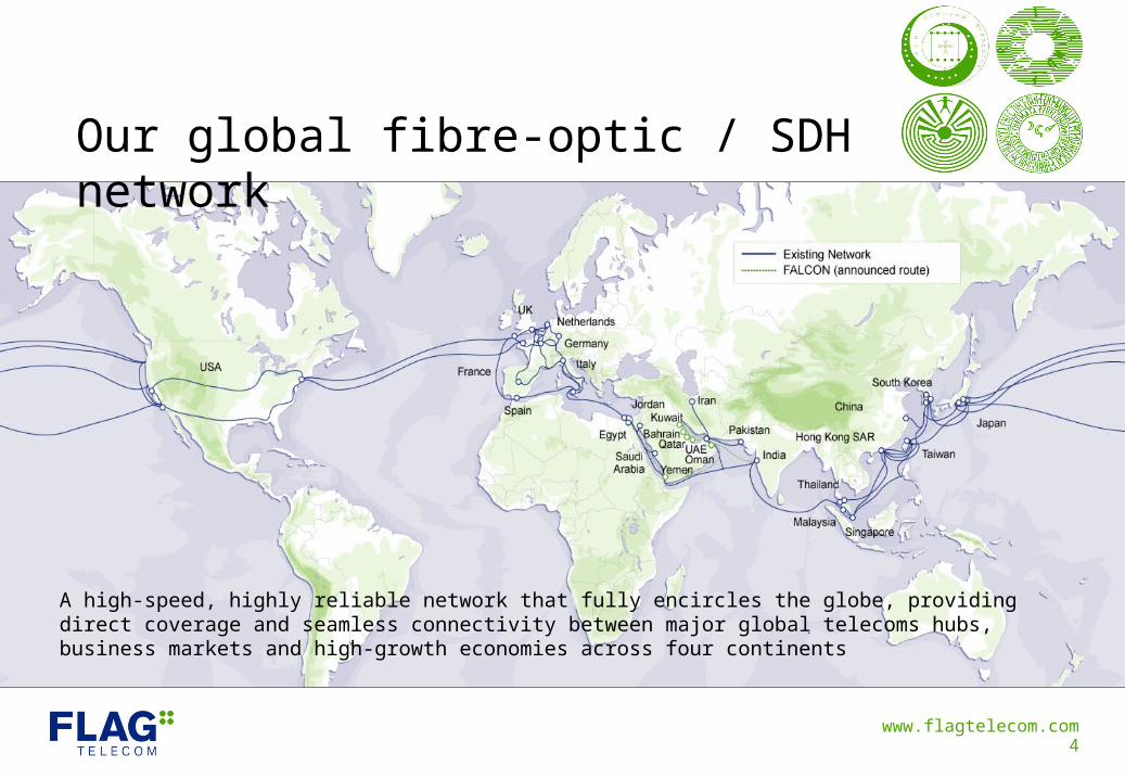
Our global fibre-optic / SDH network
A high-speed, highly reliable network that fully encircles the globe, providing direct coverage and seamless connectivity between major global telecoms hubs, business markets and high-growth economies across four continents
www.flagtelecom.com5
Architecture overviewThe FLAG global network is fully optical and is predominantly a submarine based network• Terrestrial networks are implemented to provide backhaul connectivity to domestic city nodes, and to provide
terrestrial links between submarine segments (USA, Europe, Egypt, Thailand)
It is designed, engineered and operated to provide highly reliable, scalable and cost effective transmission
FLAG adheres to industry standards in all aspects on our network, engineering, service delivery and operations
The network is fully SDH / SONET compatible and supports a wide range of standard optical and electrical interfaces and speeds for customer circuits
FLAG works with leading vendors for all component elements of the network
FLAG nodes are located in key landing stations and ‘carrier hotels’ to provide ready access to other networks
www.flagtelecom.com6
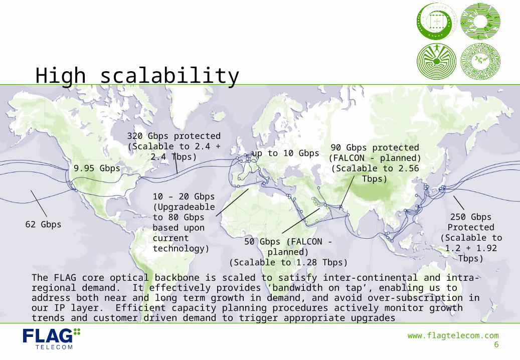
High scalability
250 Gbps Protected
(Scalable to 1.2 + 1.92 Tbps)
10 – 20 Gbps(Upgradeable to 80 Gbps based upon current technology)
320 Gbps protected(Scalable to 2.4 + 2.4 Tbps)
9.95 Gbps
62 Gbps
50 Gbps (FALCON - planned)(Scalable to 1.28 Tbps)
90 Gbps protected(FALCON - planned)
(Scalable to 2.56 Tbps)
up to 10 Gbps
The FLAG core optical backbone is scaled to satisfy inter-continental and intra-regional demand. It effectively provides ‘bandwidth on tap’, enabling us to address both near and long term growth in demand, and avoid over-subscription in our IP layer. Efficient capacity planning procedures actively monitor growth trends and customer driven demand to trigger appropriate upgrades
www.flagtelecom.com7
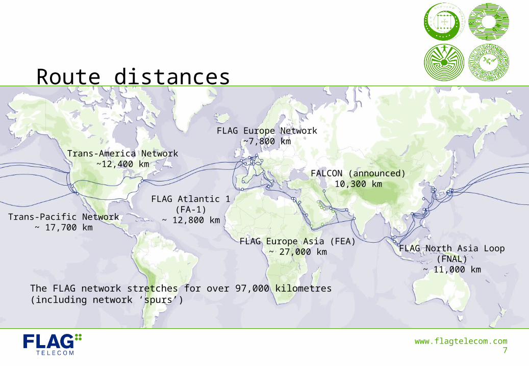
Route distances
FLAG North Asia Loop(FNAL)
~ 11,000 km
FLAG Atlantic 1(FA-1)
~ 12,800 km
FLAG Europe Asia (FEA)~ 27,000 km
FLAG Europe Network~7,800 km
Trans-America Network~12,400 km
Trans-Pacific Network~ 17,700 km
FALCON (announced)10,300 km
The FLAG network stretches for over 97,000 kilometres (including network ‘spurs’)
www.flagtelecom.com8
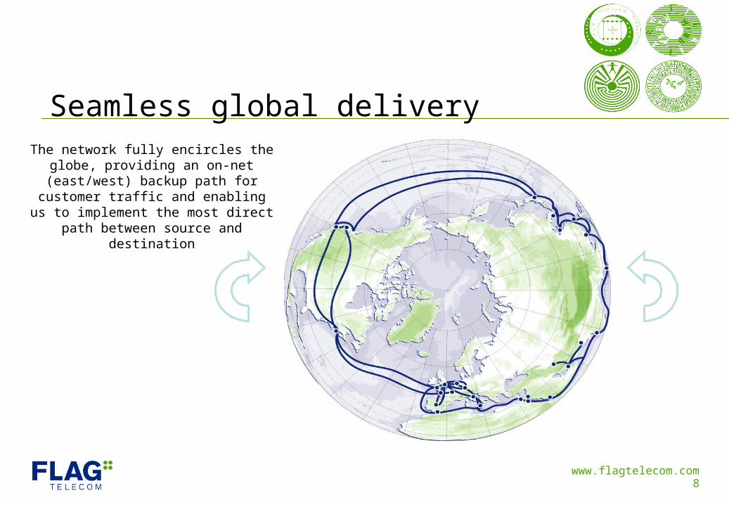
Seamless global deliveryThe network fully encircles the globe,
providing an on-net (east/west) backup path for customer traffic and enabling us
to implement the most direct path between source and destination
www.flagtelecom.com9
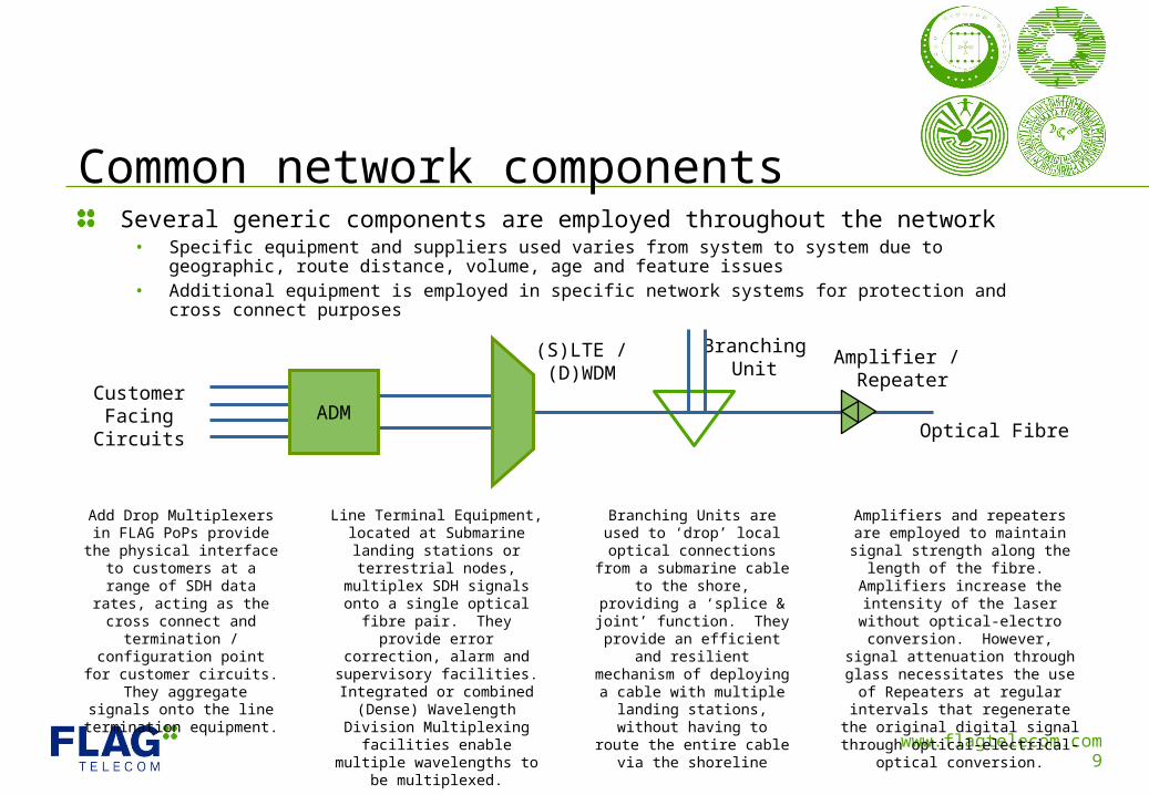
Several generic components are employed throughout the network• Specific equipment and suppliers used varies from system to system due to geographic, route distance,
volume, age and feature issues• Additional equipment is employed in specific network systems for protection and cross connect purposes
Common network components
Optical Fibre
Amplifier / Repeater
BranchingUnit
(S)LTE /(D)WDM
ADMCustomer
FacingCircuits
Add Drop Multiplexers in FLAG PoPs provide the
physical interface to customers at a range of SDH data rates, acting as the cross
connect and termination / configuration point for
customer circuits. They aggregate signals onto the line termination equipment.
Line Terminal Equipment, located at Submarine landing stations or terrestrial nodes, multiplex SDH signals onto a single optical fibre
pair. They provide error correction, alarm and supervisory facilities. Integrated or combined
(Dense) Wavelength Division Multiplexing facilities enable multiple wavelengths to be
multiplexed.
Amplifiers and repeaters are employed to maintain signal strength
along the length of the fibre. Amplifiers increase the intensity of
the laser without optical-electro conversion. However, signal
attenuation through glass necessitates the use of Repeaters at regular intervals that regenerate the original digital signal through optical-
electrical-optical conversion.
Branching Units are used to ‘drop’ local optical
connections from a submarine cable to the shore, providing a ‘splice & joint’ function. They
provide an efficient and resilient mechanism of deploying a cable with
multiple landing stations, without having to route the
entire cable via the shoreline
www.flagtelecom.com10
Performance measuresA range of measures are taken to protect FLAG’s global network and to ensure highly resilient and reliable traffic delivery
Automatic or manual protection paths are used throughout the network for protected customer circuits
A range of common automatic protection techniques are used within specific FLAG system components:• Sub Network Connection Protection (SNCP), Multiplex Section – Shared Protection Ring (MS-SPRing) or
Mutiplex Section Protection (MSP1+1) network and interface cards
FLAG is able to provide on-net east/west protection paths where appropriate
Further specific measures are taken for individual network systems• Including fibre diversity, SDH loops, Optical Protection Switching (OPS), span switching, dual access cards
etc.
Subsea cables follow carefully plotted routes, are extensively armoured and are buried close to shore to minimise the impacts of natural disasters and the risk of local cuts
All PoPs are strictly engineered to ensure carrier-grade performance• Include all necessary cabling, access, environmental, power and security failsafes
www.flagtelecom.com11
Long standing reputation foroutstanding quality & performance
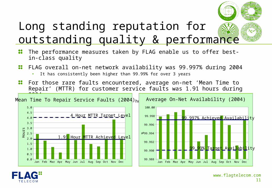
The performance measures taken by FLAG enable us to offer best-in-class quality
FLAG overall on-net network availability was 99.997% during 2004• It has consistently been higher than 99.99% for over 3 years
For those rare faults encountered, average on-net ‘Mean Time to Repair’ (MTTR) for customer service faults was 1.91 hours during 2004• It has consistently been lower than 4 hours for over 3 years
Mean Time To Repair Service Faults (2004)
Hou
rs
0.0
5.0
4.5
4.0
3.5
3.0
2.5
2.0
1.5
1.0
0.5
Jan DecFeb Mar Apr May Jun Jul Aug Sep Oct Nov
1.91 Hour MTTR Achieved Level
4 Hour MTTR Target Level
99.988
99.996
99.994
99.992
99.990
100.00
99.998
Jan DecFeb Mar Apr May Jun Jul Aug Sep Oct Nov
Average On-Net Availability (2004)
%
99.99% Target Availability
99.997% Achieved Availability
www.flagtelecom.com12
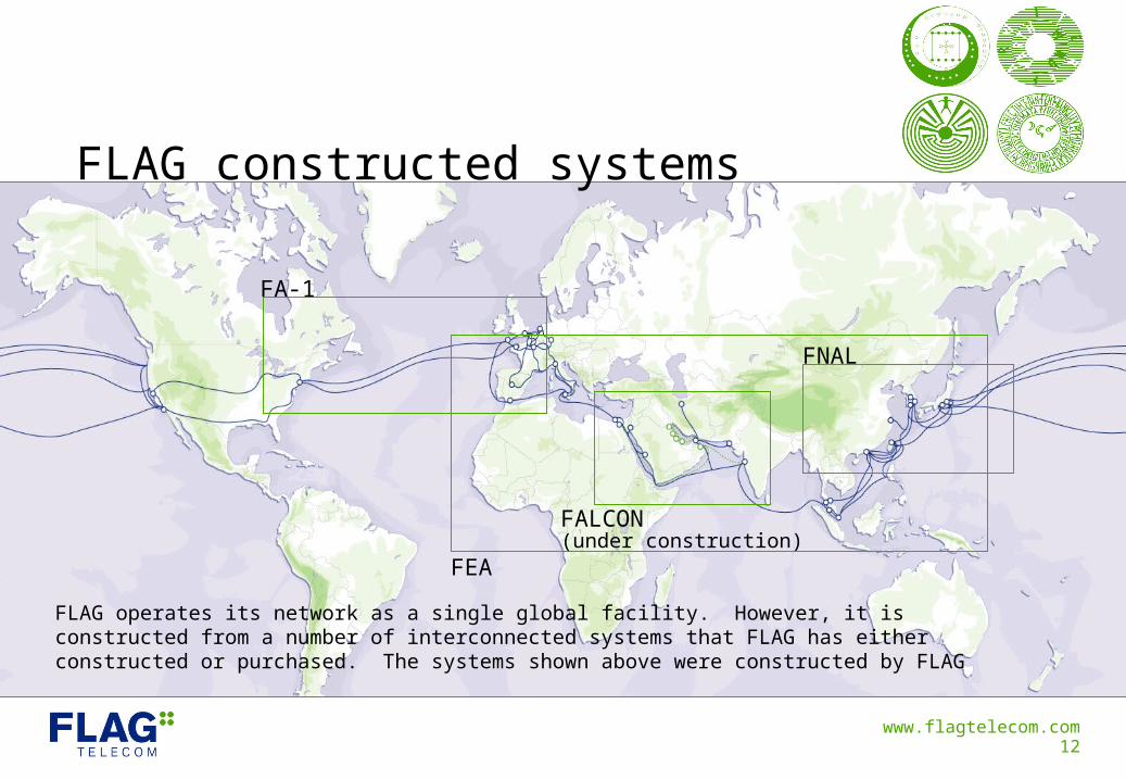
FLAG constructed systems
FLAG operates its network as a single global facility. However, it is constructed from a number of interconnected systems that FLAG has either constructed or purchased. The systems shown above were constructed by FLAG
FA-1
FEA
FNAL
FALCON(under construction)
www.flagtelecom.com13
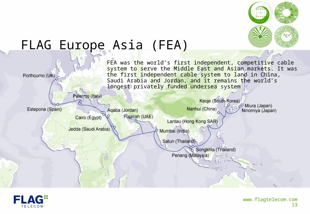
FLAG Europe Asia (FEA)FEA was the world’s first independent, competitive cable system to serve the Middle East and Asian markets. It was the first independent cable system to land in China, Saudi Arabia and Jordan, and it remains the world’s longest privately funded undersea system
www.flagtelecom.com14
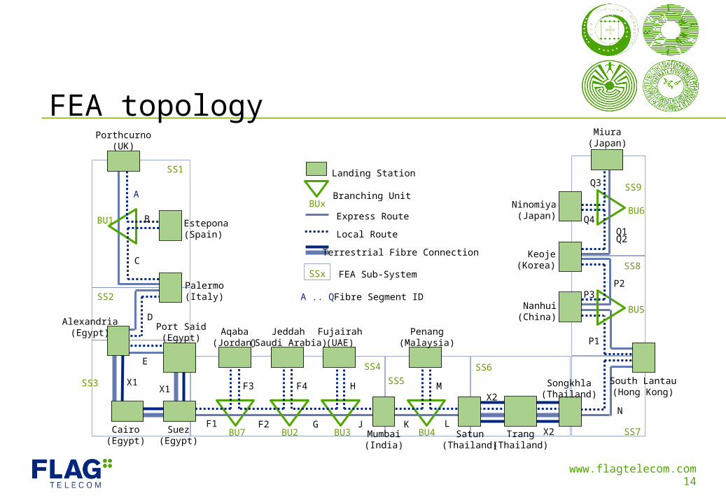
FEA topologyPorthcurno
(UK)
Estepona(Spain)
Palermo(Italy)
Alexandria(Egypt)
Cairo(Egypt)
Port Said(Egypt)
Suez(Egypt)
Aqaba(Jordan)
Jeddah(Saudi Arabia)
Fujairah(UAE)
Mumbai(India)
Penang(Malaysia)
Satun(Thailand)
Trang(Thailand)
Songkhla(Thailand)
South Lantau(Hong Kong)
Nanhui(China)
Keoje(Korea)
Ninomiya(Japan)
Miura(Japan)
SS1
SS2
SS3
SS4
SS5
SS6
SS7
SS8
SS9
BU1
BU2 BU3BU7 BU4
BU5
BU6
A
B
C
D
E
X1X1
F1 F2
F3 F4 H
G J K
M
LX2
X2
N
P1
P2P3
Q1Q2
Q3
Q4
Landing Station
BUxBranching Unit
Express Route
Local Route
Terrestrial Fibre Connection
SSx FEA Sub-System
A .. Q Fibre Segment ID
www.flagtelecom.com15
FEA overviewFLAG constructed, owns and operates FEA
In-service: 1997
FEA consists of nine sub-systems, comprising a total of 25 segments• This identification scheme is used for construction, operations & maintenance and restoration purposes
Each sub-system comprises two or more terminal stations connected by two fibre pairs• Express and local fibres
‘Local’ and ‘Express’ route configuration provides efficient and high performance delivery• ‘Express’ route provides a rapid path between high volume routes to minimise delivery delay for inter-continental
circuits• ‘Local’ route provides a local access and intra-regional capability
WDM used to increase capacity in the system from the initial 10 Gbps capacity• Current technology will allow an upgrade to 80 Gbps
FEA is resiliently interconnected with FA-1 in the UK and FNAL in Hong Kong and Japan• UK interconnect: Porthcurno – Skewjack• Hong Kong interconnect: Tong Fuk – South Lantau• Japan interconnect: Miura - Wada
www.flagtelecom.com16
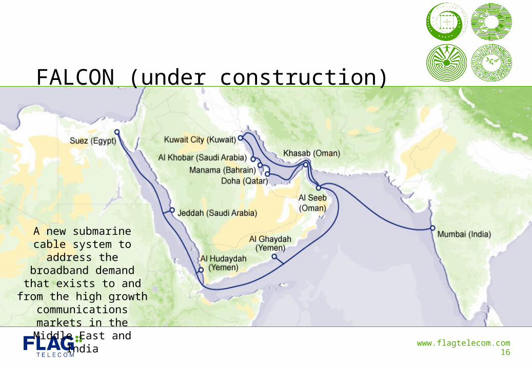
FALCON (under construction)
A new submarine cable system to address the
broadband demand that exists to and from the high
growth communications markets in the Middle East
and India
www.flagtelecom.com17
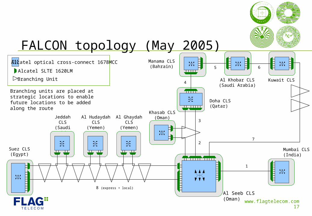
FALCON topology (May 2005)
Al Seeb CLS(Oman)
Khasab CLS(Oman)
Manama CLS(Bahrain)
Kuwait CLS
Mumbai CLS(India)
1
8 (express + local)
2
3
4
5 6
7
Alcatel optical cross-connect 1678MCC
Alcatel SLTE 1620LM
Branching Unit
Branching units are placed at strategic locations to enable future locations to be added along the route Doha CLS
(Qatar)
Al Khobar CLS(Saudi Arabia)
JeddahCLS
(Saudi Arabia)
Suez CLS(Egypt)
Al Hudaydah CLS
(Yemen)
Al GhaydahCLS
(Yemen)
www.flagtelecom.com18
FALCON system profileSuez-Muscat-Mumbai• 6,900km submarine system with 90 Gbps initial capacity• Four fibre pairs, with design capacity of 64 wavelengths per fibre pair, equalling 2.56 Tbps
Gulf Loop• Self healing 3,400km loop system with 50 Gbps initial capacity• Two fibre pairs, with design capacity of 64 wavelengths per fibre pair, equalling 1.28 Tbps
The system has been designed to enable additional ‘spurs’ to be inserted during and post initial cable deployment• Branching units inserted at key locations during first lay to support other interested landing parties along the
route as their communications needs develop and grow
Further extensions under review
Advanced network engineering design• Comprehensive protection mechanisms (optical protection, MSP1+1, MS-Spring, SDH), equipment
redundancy built into SLTE, PFE, power etc., dual landing points wherever possible, double armoured and buried cable where necessary
www.flagtelecom.com19
FALCON overview (Q3 2005)FLAG is managing the entire design, construction and operations process
Planning phase complete and route selected (Q1 / Q2 2005)• Thorough planning phase included geophysical, oceanographic, hydrodynamic (sediment, current movement) and
environmental analysis, plus an analysis of human factors such as external aggression, pipelines (oil, gas, & sewage outfalls etc), cables (military, power & telecoms etc), commercial fisheries, dredging and shipping activities.
• Marine surveys, landing site reviews and permit activities complete
Supplier contract awarded to Alcatel, a leading provider of large-scale turnkey submarine cable projects
Implementation phase underway• Cable anchored in Oman and en-route to Mumbai early August 2005
Initial RFS in Q4 ‘05
Negotiations with other interested landing parties are continuing• Design enables spurs to be added along the cable route to match evolving local communications requirements
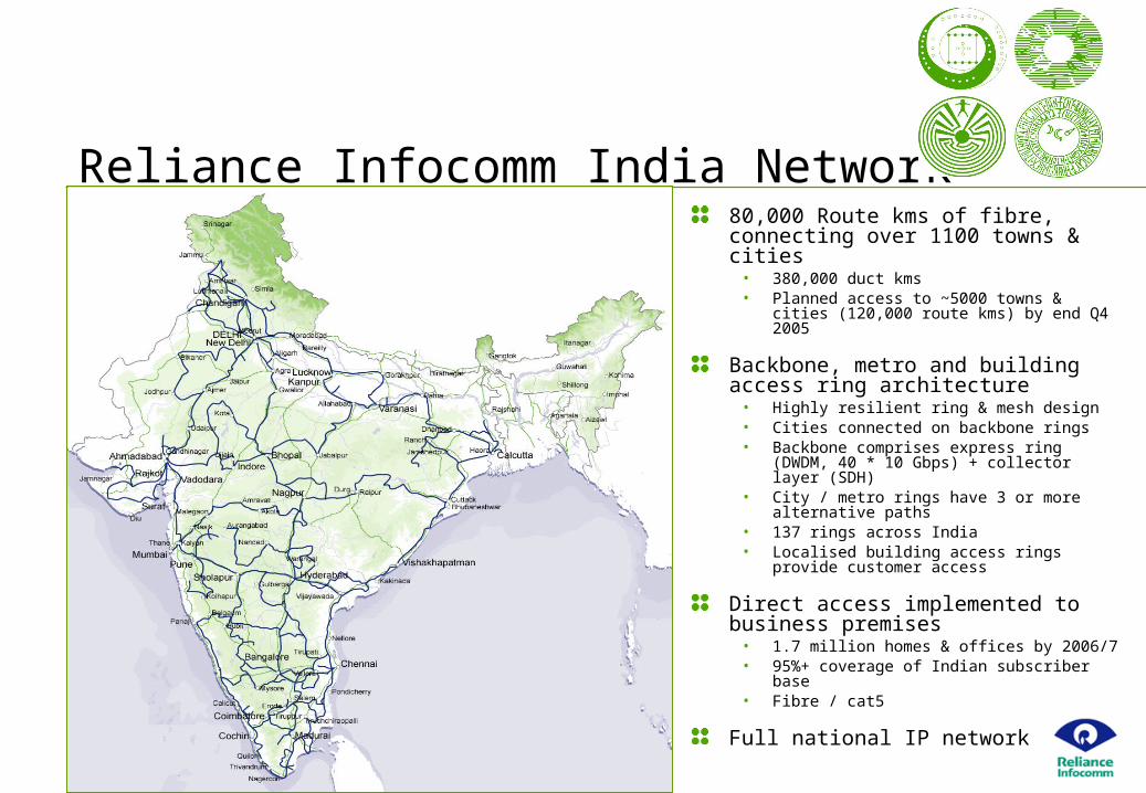
Reliance Infocomm India Network80,000 Route kms of fibre, connecting over 1100 towns & cities• 380,000 duct kms • Planned access to ~5000 towns & cities
(120,000 route kms) by end Q4 2005
Backbone, metro and building access ring architecture• Highly resilient ring & mesh design• Cities connected on backbone rings• Backbone comprises express ring (DWDM,
40 * 10 Gbps) + collector layer (SDH)• City / metro rings have 3 or more
alternative paths• 137 rings across India• Localised building access rings provide
customer access
Direct access implemented to business premises• 1.7 million homes & offices by 2006/7• 95%+ coverage of Indian subscriber base• Fibre / cat5
Full national IP network
www.flagtelecom.com21
FLAG metro rings & extended reachFLAG owns and operates metro rings, connecting major telehouses in the following locations:• London• New York• Paris• Tokyo
FLAG employs leased line connectivity in other cities with more than one node (SDH / IP)• Amsterdam• Hong Kong• Singapore• Madrid
Extended reach into all other locations is performed via FLAG’s approved suppliers and partners worldwide
www.flagtelecom.com22
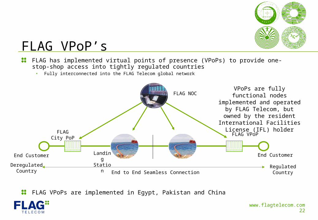
FLAG VPoP’sFLAG has implemented virtual points of presence (VPoPs) to provide one-stop-shop access into tightly regulated countries• Fully interconnected into the FLAG Telecom global network
FLAG VPoPs are implemented in Egypt, Pakistan and China
VPoPs are fully functional nodes implemented and operated by FLAG Telecom, but owned by
the resident International Facilities License (IFL) holder
FLAG NOC
End CustomerEnd Customer
FLAGCity PoP
FLAG VPoP
LandingStation
End to End Seamless Connection
DeregulatedCountry
RegulatedCountry
www.flagtelecom.com23
Global operations & service managementOur global structure and network ownership enable us to offer effective and responsive service management
Order Project Managers ensure timely and tested delivery of your service
We operate a resilient, global Network Operations Centre (NOC)• NOCs are staffed by technical professionals, with specific expertise in subsea, transmission and IP network
elements and technologies
We employ highly skilled engineers and technical experts• We recruit at degree level and support staff include qualified & accredited engineers (CCNA, CCIE & JNCIE)
Regional field engineers are on call 24*7 on a global basis• Coordinated by a central management function• Global Field Operations team has remote access to network management systems
Strict escalation and customer communications procedures are in place• Focused on resolving faults and restoring your service quickly and efficiently, keeping you informed throughout
www.flagtelecom.com24
Network Operations and ManagementFLAG operates a primary NOC in Heathrow (UK), secondary NOC in Fujairah (UAE) and a Disaster Recovery NOC in London Docklands
The NOC proactively monitors FLAG’s network and facilities 24 hour-a-day, seven day-a -week • Monitors network elements, identifying alarms and performing root cause analysis• Monitors environmental alarms, including intrusion, high/low temperature, fire or smoke, toxic/explosive gas,
DC/commercial AC power and water levels
The NOC is supported by integrated operational support systems (OSS), optimally configured to detect & pinpoint faults to the individual network segment, handle incidents and quickly re-route traffic whenever necessary• Including Micromuse Netcool (high-level alarm fault isolation), Peregrine Service Centre / Trouble Management
(trouble ticket system) & Cramer Dimension (circuit provisioning system)
Centralised Operations (co-located with the FLAG NOC) are the control point for the network, logging and authorising all network activity • Responsible for repairing and restoring any customer circuit outages or any other events that happen on the network
Field engineering / operations resources manage all localised repair and maintenance activities
www.flagtelecom.com25
FLAG transmission services
FLAG Right of Use (RoU)• A long-term contract providing the right to use capacity between specific points on the FLAG network
FLAG Capacity Service• Protection is not guaranteed• Full or half circuit connectivity• Between landing stations, city nodes or customer premises• Targeted at major carriers that manage their own international facilities, back-up routes and restoration plans• One-top-shop service, facilitating all aspects of international delivery• Supporting all customer traffic types and applications, including voice, video and data
FLAG Managed Bandwidth Service (MBS)• Protected, offering maximum performance and resilience• Seamless, fully managed connectivity• Between landing stations, city nodes or customer premises • Targeted at major carriers that manage their own international facilities• One-stop-shop service, facilitating all aspects of international delivery• Supporting all customer traffic types and applications, including voice, video and data
FLAG offers a range of bandwidth services to support the global connectivity requirements of our customers. Services are available at a wide range of speeds and with flexible contract terms. Optional co-location is available in major city centres
www.flagtelecom.com26
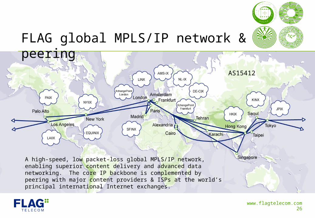
FLAG global MPLS/IP network & peering
AS15412
A high-speed, low packet-loss global MPLS/IP network, enabling superior content delivery and advanced data networking. The core IP backbone is complemented by peering with major content providers & ISPs at the world’s principal international Internet exchanges.
www.flagtelecom.com27
SummaryWe own and manage the entire network, providing maximum control over service cost and quality• Network either self-constructed or acquired on IRU / long-term lease basis
We have service operator licenses in key liberalised markets and maintain strong relationships with the incumbent telecoms operators in all locations in which we operate
We offer extended reach as a standard option via city Points of Presence (PoPs), metro rings and local tails• Access to service is available from city centre locations, landing stations and customer premises
Our network fully encircles the globe, enabling seamless traffic delivery both eastward and westward • FLAG strives to always provide customers with the most direct path between source and destination and are
able to provide an on-net backup path
High scalability enables us to provide a full range of data speeds
An extensive range of measures are implemented to ensure maximum availability and minimum disruption to customers
Thank YouFor further information, please visit www.flagtelecom.com for the contact details of your local FLAG Telecom representative
The information in this presentation is provided for information purposes only. All reasonable efforts are used to ensure and maintain accuracy at the time of publishing. Future events may change its accuracy. No representation or warranty is given by any person as to its accuracy or completeness and it should not be relied upon.
www.flagtelecom.comFLAG Telecom Ltd. ProprietaryFor Information Only