flange type of differential pressure...
TRANSCRIPT

No. SS2-GTX00F-0100 (Rev.13)
AT9000 Advanced TransmitterFlange type of Differential Pressure Transmitter
Specifications are subject to change without notice. - 1 - “This product is designed for general industrial use.”
OVERVIEWAT9000 Advanced Transmitter is a micropro-cessor-based smart transmitter that features high performance and excellent stability. Capable of measuring gas, liquid, and vapor, and liquid lev-els, it transmits 4 to 20 mA DC analog and digi-tal signals according to the measured differential pressure.It can also execute two-way communications between the Smart Communicator or HART® 375 communicator, thus facilitating self-diagno-sis, range resetting, and automatic zero adjust-ment.
FEATURESExcellent stability and high performance• Long-term stability is proven in 500,000 instal-
lations worldwide.• Unique characterization and composite semi-
conductor sensors realize excellent temperature and static pressure characteristics.
A diverse lineup• A diverse flange lineup, ranging from small
diameter 1.5 inch (40 mm) and 2 inches (50 mm) to 3 inches (80 mm), is available to meet user requirements.
• A wide variety of models, including those for standard differential pressure and high differ-ential pressure, is available to meet user requirements.
• A wide variety of corrosion-resistant materials for wetted parts is also available.
Remote communication• Two-way communication using digital output
facilitates self-diagnosis, range resetting, auto-matic zero adjustment, and other operations.
• HART® protocol communication is available. (Option)
China RoHSThis device is used in the Oil & Gas, Petrochem-ical, Chemical, Pulp & Paper, Food & Beverage, Machinery, Steel/Metal & Mining, and Automo-bile industries and therefore does not fall under the China RoHS Legislation.If this device is used in semiconductor manufac-turing equipment, labeling on the device and documents for the China RoHS may be required. If such documents are required, consult an Azbil Corp. representative.
HART® is a registered trademark of the HART Communication Foundation.

No. SS2-GTX00F-0100 (Rev.13) Azbil Corporation
- 2 -
APPLICATIONPetroleum / Petrochemical / ChemicalFor measuring pressures, liquid levels, and ordinary sur-face levels in tanks of all sizes.
Electric power / City gas / Other utilitiesFor measurement applications that require high degrees of stability and accuracy.
Pulp and paper• For lines that need transmitters resistant to chemical liq-
uids, corrosive fluids and the like.• For measuring pressures, liquid levels, and boundary
surface levels in tanks• For measuring pressure, liquid levels, and boundary sur-
face levels in tanks of all sizes.
Iron and steel / Nonferrous metal / CeramicsFor lines that require stable measurement under strictly controlled (temperature, humidity, etc.) conditions.
Machinery / ShipbuildingFor lines that require stable measurement under strictly controlled (temperature, humidity, etc.) conditions.
FUNCTIONAL SPECIFICATIONSType of protectionNEMA3 and 4XIEC IP67
FM Explosionproof and Dust ApprovalsExplosionproof for Class I, Division 1, Groups A, B, C and D; Class I, Zone 1, AEx d IICDust-Ignitionproof for Class II, III, Division 1, Groups E, F and GT5 -40°C < Tamb < +85°CHazardous locationsIndoor / Outdoor Type 4X, IP67Factory sealed, conduit seal not required for Division applicationsCaution - Use supply wires suitable for 5°C above sur-rounding ambient
FM Intrinsically safe Approval IS/I,II,III/1/ABCDEFG/T4; -40 °C < Tamb < +60 °C; 80395278, 80395279,80395280; Entity; TYPE 4X; IP67 I/0/ AEx ia/IIC/T4; -40 °C < Tamb < +60 °C;80395278, 80395279, 80395280; Entity; TYPE 4X;IP67Entity Parameters: Vmax(Ui)=30 Volts, Imax(Ii)=100mA, Pi=1W, Ci=10nF, Li=0.5mH
FM Nonincendive ApprovalNI/I/2/ABCD/T4; -40 °C < Tamb < +60 °C;80395494; NIFW; TYPE 4X; IP67 NI/I/2/IIC/T4; -40 °C < Tamb < +60 °C; 80395494; NIFW; TYPE 4X; IP67S/II,III/1/EFG/T4; -40 °C < Tamb < +60 °C; 80395494;NIFW; TYPE 4X; P67Nonincendive Field Wiring Parameters: Vmax(Ui)=30 Volts, Ci=10nF, Li=0.5mH
ATEX Flameproof and Dust Certifications 0344 KEMA 08ATEX0004
II 1/2 G Ex d IIC T6 Tprocess=85°C -30°C < Tamb < +75°C IP66/67II 1/2 G Ex d IIC T5 Tprocess=100°C -30°C < Tamb < +80°C IP66/67II 1/2 G Ex d IIC T4 Tprocess=110°C -30°C < Tamb < +80°C IP66/67II 2 D Ex tD A21 IP66/67 T85 Tprocess=85°C -30°C < Tamb < +75°CII 2 D Ex tD A21 IP66/67 T100 Tprocess=100°C -30°C < Tamb < +75°CII 2 D Ex tD A21 IP66/67 T110 Tprocess=110°C -30°C < Tamb < +75°CCaution - Use supply wires suitable for 5°C above sur-rounding ambientATEX Intrinsic safety and Dust Certifications
0344 KEMA 07ATEX0200 X
II 1 G Ex ia IIC T4 TPROCESS = 105 °C -30 °C < Tamb < +60 °C IP66 / 67ELECTRICAL PARAMETERS: Ui = 30 V, Ii = 93 mA, Pi = 1 W, Ci = 5 nF, Li = 0.5 mHII 1 D Ex iaD 20 IP66 / 67 T105 TPROCESS = 105 °C -30 °C < Tamb < +60 °CATEX Type n and Dust Certifications 0344 KEMA 07ATEX0200 X
II 3 G Ex nL IIC T4 TPROCESS = 105 °C -30 °C < Tamb < +60 °C IP66 / 67ELECTRICAL PARAMETERS: Ui = 30 V, Ci = 5 nF, Li = 0.5 mHII 2 D Ex tD A21 IP66 / 67 T85 TPROCESS = 85 °C -30 °C < Tamb < +75 °CII 2 D Ex tD A21 IP66 / 67 T100 TPROCESS = 100 °C -30 °C < Tamb < +80 °CII 2 D Ex tD A21 IP66 / 67 T110 TPROCESS = 110 °C -30 °C < Tamb < +80 °CNEPSI Flameproof and Dust Certifications Ex d IIC T6 DIP A21 TA 85°C Tprocess=80°C -40°C < Tamb < +75°CEx d IIC T5 DIP A21 TA 100°C Tprocess=95°C -40°C < Tamb < +80°CEx d IIC T4 DIP A21 TA 115°C Tprocess=110°C -40°C < Tamb < +80°CENCLOSURE TYPE IP66/67Certificate No. GYJ071268
NEPSI Intrinsic Safety CertificationEx ia IIC T4 Tprocess=105°C -40°C < Tamb < +60°CEnclosure IP66 / 67Electrical Parameters: Ui=30V, Ii=100mA, Pi=1W, Ci=13nF, Li=0.5mHCertificate No. GYJ071269NEPSI Type n CertificationEx nL IIC T4 Tprocess=110°C -40°C < Tamb < +60°CEnclosure IP66 / 67Electrical Parameters: Ui=30V, Ii=100mA, Pi=1W, Ci=13nF, Li=0.5mHCertificate No. GYJ071269

Azbil Corporation No. SS2-GTX00F-0100 (Rev.13)
- 3 -
IECEx Flameproof and Dust CertificationsCertificate No. IECEx KEM 08.0001Ga/Gb Ex d IIC T6 Tprocess=85°C -30°C < Tamb < +75°C IP66/67Ga/Gb Ex d IIC T5 Tprocess=100°C -30°C < Tamb < +80°C IP66/67Ga/Gb Ex d IIC T4 Tprocess=110°C -30°C < Tamb < +80°C IP66/67Ex tD A21 IP66/67 T85 Tprocess=85°C -30°C < Tamb < +75°CEx tD A21 IP66/67 T100 Tprocess=100°C -30°C < Tamb < +75°CEx tD A21 IP66/67 T110 Tprocess=110°C -30°C < Tamb < +75°CCaution - Use supply wires suitable for 5°C above sur-rounding ambientIECEx Intrinsic safety and Dust Certifications IECEx KEM 07.0058XZone 0 Ex ia IIC T4 TPROCESS = 105 °C
-30 °C < Tamb < +60 °C IP66 / 67ELECTRICAL PARAMETERS: Ui = 30 V, Ii = 93 mA, Pi = 1 W, Ci = 5 nF, Li = 0.5 mH
Ex iaD 20 IP66 / 67 T105 TPROCESS = 105 °C -30 °C < Tamb < +60 °C
IECEx Type n and Dust Certifications IECEx KEM 07.0058XEx nL IIC T4 TPROCESS = 105 °C -30 °C < Tamb < +60 °C IP66 / 67ELECTRICAL PARAMETERS: Ui = 30 V, Ci = 5 nF, Li = 0.5 mHEx tD A21 IP66 / 67 T85 TPROCESS = 85 °C -30 °C < Tamb < +75 °CEx tD A21 IP66 / 67 T100 TPROCESS = 100 °C -30 °C < Tamb < +80 °CEx tD A21 IP66 / 67 T110 TPROCESS = 110 °C -30 °C < Tamb < +80 °C
KOSHA Flameproof (Code K1)Ex d II C T6 Tprocess = 85 °C -30 °C < Tamb < +75 °CEx d II C T5 Tprocess = 100 °C -30 °C < Tamb < +80 °CEx d II C T4 Tprocess = 110 °C -30 °C < Tamb < +80 °C
EMC Conformity89/336/EEC, 92/31/EEC, 93/68/EEC Electromagnetic Compatibility (EMC) Directive
Measuring span / Setting range / Working pressure range
Figure 1 Working pressure and temperature of wetted parts section
Figure 2 Working pressure and temperature of wetted parts section (for oxygen and chlorine service)
Measuring span Setting range Working pressure range
GTX 35F
2.5 to100kPa{250 to 10160
mmH2O}
-100 to 100kPa{-10160 to 10160
mmH2O}Up to flange rating(for negative pres-sures, see Figure 1 and Figure 2)GTX
60F35 to 3500kPa
{0.35 to 35 kgf/cm2}-100 to 3500kPa{-1~35 kgf/cm2}
133.3{1000}
101
80
53
27
13
8.05.3
1.3
2.0{15}
-50-40 40 50 60 70 80 90 100110 115
Normal operating range
Op
erat
ive
limit
Unusable range
Op
erat
ive
limit
Temperature of wetted parts ( C)
Wo
rkin
g P
ress
ure
P (k
Pa a
bs/
{mm
Hg
})
133.3
101.3
53
-40 -10 0 40 75 80
Normal operating range
Wo
rkin
g p
ress
ure
P
kPa
{mm
Hg
}
Temperature of wetted parts ( C)
Unusable range
{1000}
{760}
{400}

No. SS2-GTX00F-0100 (Rev.13) Azbil Corporation
- 4 -
Supply voltage and load resistance17.9 to 42V DC. Reverse polarity protection is standard. A load resistance of 250 Ω or more is necessary between loops. See Figure 3.
Figure 3 .Supply voltage vs. load resistance characteristics
Note) For communication with HART communicator, a load resistance of 250 Ω or more is necessary.
OutputAnalog output (4 to 20 mA DC) with DE protocolAnalog output (4 to 20 mA DC) with HART protocolDigital output (DE protocol)
Output signal3.6 to 21.6 mA3.8 to 20.5 mA (NAMUR NE43 compliant)
Failure AlarmUpper: 21.6 mA or moreLower: 3.6 mA or less
Ambient temperature limitsNormal operating range-30 to 75°C for general purpose models-10 to 75°C for oxygen and chlorine models-25 to 75°C for models with digital indicatorsOperative limits-50 to 80°C for general purpose models-40 to 80°C for oxygen and chlorine models-30 to 80°C for models with digital indicators
Temperature ranges wetted partsNormal operating range-40 to 110°C for general purpose models-20 to 75°C for oxygen and chlorine modelsOperative limits-50 to 115°C for general purpose models-40 to 80°C for oxygen and chlorine models
Ambient humidity limits5 to 100% RH
Stability against supply voltage change± 0.005% FS/V
Response time Max: 0.3 sec.
Damping timeSelectable from 0 to 32 sec. in ten stages
Lightning protectionApplicable Standards; IEC 61000-4-5Peak value of current surge(80/20μ sec.): 6000A
IndicatorThe digital LCD indicator (optional) indicates engineering units and can be set freely between -99999 and 99999 (5 digits). For meter calibration, specify the following items when placing your order.• Meter calibration range• Meter calibration unit• Linear / Square-root for meter indication.
Various kinds of data can be set using the Smart Com-
municator or the HART®375 communicator.
Bolts and nuts materials (for fastening meter body cover)Carbon steel (SNB7), 304 SST, 630 SST
PaintStandardCorrosion-resistant paint (Baked acrylic paint)Corrosion-proof finishCorrosion-proof paint (Baked urethane paint), fungus-proof finishCorrosion-resistant finish (silver color) Transmitter case is coated with silver paint in addition to the above corrosion-resistant finish.
OPTIONAL SPECIFICATIONSFEP protective filmUse FEP protective films when corrosive fluids are used or to avoid metal ions contact.
Working temperature range0 to 110°CWorking pressure range Atmospheric pressure to flange rating(up to JIS10K, ANSI / JPI 150)(Not usable under negative pressure)
Oil free finishThe transmitter is shipped with oil-free wetted parts.
External zero/span adjustment functionThe transmitter can be easily zero/span adjusted in the field.
ElbowThis is an adaptor for changing the electrical conduit con-nection port from the horizontal to the vertical direction, if required by wiring conditions in the field. One or two elbows may be used as needed.
Conformance to SI unitsWe deliver transmitters set to any SI units as specified.
1345
1482
Load resistance (W)
Supply voltage - 12.5
0.0219
245
0 17.9 42 45
Load
resi
stan
ce (Ω
)
Supply voltage (V DC)
Operating Range
=
Ope
rativ
e lim
it
12.5

Azbil Corporation No. SS2-GTX00F-0100 (Rev.13)
- 5 -
PHYSICAL SPECIFICATIONSMaterials
Fill fluidSilicone oil for general purpose modelsFluorine oil for oxygen and chlorine modelsCenter body316 SSTTransmitter caseAluminum alloy, CF8M (Equivalent to 316 SST)Meter body coverSCS14A (equivalent to 316 SST) or 316 SSTFor Wetted parts
Adapter flange (option)SCS14A (equivalent to 316 SST)Center body316 SST (316L SST for diaphragm only)ASTM B575 (Hastelloy C-276 equivalent), Tantalum, 316L SSTVents and plugs316 SSTGasketsFEPFlange materials304 SST, 316 SST, 316L SST
WeightApprox. 5.9 kg (in case of ANSI 150# - 1-1/2 inches flange)
INSTALLATIONElectrical connection1/2NPT internal thread, M20 internal thread.
GroundingResistance 100 Ω max
MountingDirect mounting on the process side
Process connectionMeasured pressure (liquid side)
Flush diaphragmJIS 10K, 20K, 30K and 63K:40, 50 and 80mm (RF) equivalentsANSI/JPI 150, 300 and 600:1.5, 2, 3 inches (RF) equivalentsExtended diaphragmJIS 10K, 20K and 30K: 50, 80 and 100mm(RF) equivalentsANSI/JPI 150, 300 and 600:2, 3 inches (RF) equivalentsANSI/JPI 150 and 300: 4 inches (RF) equivalentsFlange standardJIS; JIS B 2220 (2004)ANSI; ANSI B 16.5 (1988)JPI; JPI-7S-15-93Standard pressure sideRc1/2, 1/2NPT internal thread, Rc1/4, 1/4NPT internal thread, atmospheric disconnection hole.
TRANSMITTER HANDLING NOTESTo get the most from the performance this transmitter can offer, please use it properly noting the points mentioned below. Before using it, please read the Instruction Manual.Transmitter installation notes
Wiring notes
� WARNING• When installing the transmitter, ensure that
gaskets do not protrude from connecting points into the process (such as adapter flange connection points and connecting pipes and flanges). Gasket protrusion may result in leaks and output errors.
• Do not use the transmitter outside its defined pressure, temperature, and connection specifications. A serious accident may otherwise occur due to damage and leaks.
• When performing wiring work in explosion-proof areas, follow the work method specified in the explosion-proof guidelines.
� CAUTION• After installing the transmitter, do not stand on it.
Using it as a foothold could cause it to collapse and cause physical injury.
• Be careful not to hit the glass indicator with tools etc. This could break the glass and cause injury.
• The transmitter is heavy. Wear safety shoes and take care when installing it.
• Impact to transmitter can damage sensor module.
� WARNING• To avoid shocks, do not perform electrical wiring
work with wet hands or with live wires.
� CAUTION• Do wiring work properly in conformance with the
specifications. Wiring mistakes may result in malfunction or irreparable damage to the instrument.
• Use a power supply that conforms to the specifications. Use of an improper power supply may result in malfunction or irreparable damage to the instrument.

No. SS2-GTX00F-0100 (Rev.13) Azbil Corporation
- 6 -
Handling precautions for HART specifi-cation devices• If you need to operate with a secondary host (HART com-
municator, etc.), set the communication interval of the pri-mary host (DCS, device management system) to 8 seconds or more, or suspend communication from the primary host. If the primary host repeats HART communication within 8 seconds, the request from the secondary host may not be received (communication may not be possible).
• If electrical noise in the environment prevents HARTcom-munications with the host, take countermeasures such as separating the signal cables from the source of the noise, improving the grounding, changing to shielded signal cables, etc. Even if noise interferes with HART communi-cations, the 4-20 mA analog signal will be unaffected and can be used for control.
• If this product is being operated in multidrop mode, there is a limit to the number of devices that can be used. If you are using multidrop mode, please consult with us.
PERFORMANCE SPECIFICATIONSMax working pressure
Note) 1. Max. working pressure depends on flange rating, flange materials and operating temperature. Please refer to the following data. Operating range of temperature depends on specification of transmitters.
Note) 2. In case of flange type (GTX60F) and remote sealed type (GTX60U), max working pressure depends on the smaller value of either 1.5 MPa or fol-lowing data.
Note) 3. In case of remote sealed type (GTX71U), max working pressure depends on the smaller value of either 10 MPa or following data.
JIS JPI/ANSI
304 SST
316 SST
316L SST
12.0
10.0
8.0
6.0
4.0
2.0
0.0Max
. Wor
king
Pre
ssur
e (M
Pa)
63K
40K30K
20K
10K
12.0
10.0
8.0
6.0
4.0
2.0
0.0Max
. Wor
king
Pre
ssur
e (M
Pa)
600#
300#
150#
12.0
10.0
8.0
6.0
4.0
2.0
0.0Max
. Wor
king
Pre
ssur
e (M
Pa)
63K
40K30K
20K
10K
12.0
10.0
8.0
6.0
4.0
2.0
0.0Max
. Wor
king
Pre
ssur
e (M
Pa)
600#
300#
150#
12.0
10.0
8.0
6.0
4.0
2.0
0.0Max
. Wor
king
Pre
ssur
e (M
Pa)
63K
40K30K
20K
10K
12.0
10.0
8.0
6.0
4.0
2.0
0.0Max
. Wor
king
Pre
ssur
e (M
Pa)
600#
300#150#

Azbil Corporation No. SS2-GTX00F-0100 (Rev.13)
- 7 -
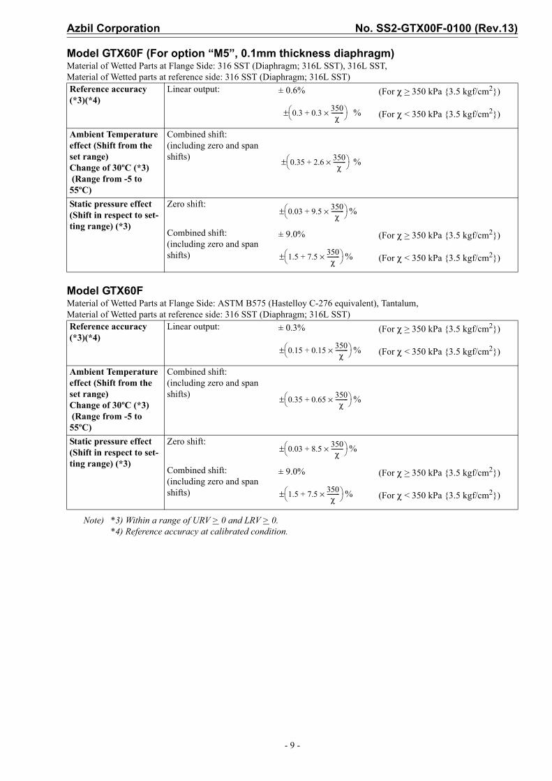
Reference accuracyShown for each item are the percentage ratio for χ (kPa), which is the greatest value of either the upper range value (URV)*1, the lower range value (LRV)*2 or the span.
Model GTX35FMaterial of Wetted Parts at Flange Side: 316 SST (Diaphragm; 316L SST), 316L SST, Material of Wetted parts at reference side: 316 SST (Diaphragm; 316L SST)
Model GTX35F (For option “M5”, 0.1mm thickness diaphragm)Material of Wetted Parts at Flange Side: 316 SST (Diaphragm; 316L SST), 316L SST, Material of Wetted parts at reference side: 316 SST (Diaphragm; 316L SST)
Note) *1) URV denotes the process value for 100% (20 mA DC) output.*2) LRV denotes the process value for 0% (4 mA DC) output.*3) Within a range of URV > 0 and LRV > 0.*4) Reference accuracy at calibrated condition.
Reference accuracy (*4)
Linear output: ± 0.2% (For χ > 12.5 kPa {1250 mmH2O})
% (For χ < 12.5 kPa {1250 mmH2O})
Ambient Temperature effect (Shift from the set range) Change of 30ºC (Range from -5 to 55ºC)
Combined shift:(including zero and span shifts)
± 1.45% (For χ > 12.5 kPa {1250 mmH2O})
% (For χ < 12.5 kPa {1250 mmH2O})
Static pressure effect (Shift in respect to set-ting range)Change of 7 MPa {70 kgf/cm2}
Zero shift:%
Combined shift: (including zero and span shifts) ±0.97% (For χ > 25 kPa {2500 mmH2O})
% (For χ < 25 kPa {2500 mmH2O})
Reference accuracy (*4)
Linear output: ± 0.8% (For χ > 12.5 kPa {1250 mmH2O})
% (For χ < 12.5 kPa {1250 mmH2O})
Ambient Temperature effect (Shift from the set range) Change of 30ºC (Range from -5 to 55ºC)
Combined shift:(including zero and span shifts) %
Static pressure effect (Shift in respect to set-ting range) Change of 7 MPa {70 kgf/cm2}
Zero shift:%
Combined shift:(including zero and span shifts)
% (For χ > 25 kPa {2500 mmH2O})
% (For χ < 25 kPa {2500 mmH2O})
0.05 0.15 12.5χ
----------×+⎝ ⎠⎛ ⎞±
0.35 1.1 12.5χ
----------×+⎝ ⎠⎛ ⎞±
0.03 0.64 25χ------×+⎝ ⎠
⎛ ⎞±
0.03 0.94 25χ------×+⎝ ⎠
⎛ ⎞±
0.15 0.3 12.5χ
----------×+⎝ ⎠⎛ ⎞±
0.6 5.4 25χ------×+⎝ ⎠
⎛ ⎞±
0.64 2.64+ 25χ------×⎝ ⎠
⎛ ⎞±
1.17 2.0+ 25χ------×⎝ ⎠
⎛ ⎞±
0.23 2.94+ 25χ------×⎝ ⎠
⎛ ⎞±

No. SS2-GTX00F-0100 (Rev.13) Azbil Corporation
- 8 -
Model GTX35FMaterial of Wetted Parts at Flange Side: ASTM B575 (Hastelloy C-276 equivalent), Tantalum, Material of Wetted parts at reference side: 316 SST (Diaphragm; 316L SST)
Model GTX60FMaterial of Wetted Parts at Flange Side: 316 SST (Diaphragm; 316L SST), 316L SST, Material of Wetted parts at reference side: 316 SST (Diaphragm; 316L SST)
Note) *3) Within a range of URV > 0 and LRV > 0.*4) Reference accuracy at calibrated condition.
Reference accuracy (*4)
Linear output: ± 0.4% (For χ > 12.5 kPa {1250 mmH2O})
% (For χ < 12.5 kPa {1250 mmH2O})
Ambient Temperature effect (Shift from the set range) Change of 30ºC (Range from -5 to 55ºC)
Combined shift:(including zero and span shifts) %
Static pressure effect (Shift in respect to set-ting range) Change of 7 MPa {70 kgf/cm2}
Zero shift:%
Combined shift:(including zero and span shifts)
% (For χ > 25 kPa {2500 mmH2O})
% (For χ < 25 kPa {2500 mmH2O})
Reference accuracy (*3)(*4)
Linear output: ± 0.15% (For χ > 350 kPa {3.5 kgf/cm2})
% (For χ < 350 kPa {3.5 kgf/cm2})
Ambient Temperature effect (Shift from the set range) Change of 30ºC (*3) (Range from -5 to 55ºC)
Combined shift:(including zero and span shifts)
± 0.75% (For χ > 350 kPa {3.5 kgf/cm2})
% (For χ < 350 kPa {3.5 kgf/cm2})
Static pressure effect (Shift in respect to set-ting range) (*3)Change of 7 MPa {70 kgf/cm2}
Zero shift:%
Combined shift:(including zero and span shifts)
± 9.00% (For χ > 350 kPa {3.5 kgf/cm2})
(For χ < 350 kPa {3.5 kgf/cm2})
0.25 0.15 12.5χ
----------×+⎝ ⎠⎛ ⎞±
0.6 2.4 25χ------×+⎝ ⎠
⎛ ⎞±
0.03 1.64+ 25χ------×⎝ ⎠
⎛ ⎞±
1.07 1.0+ 25χ------×⎝ ⎠
⎛ ⎞±
0.13 1.94+ 25χ------×⎝ ⎠
⎛ ⎞±
0.05 0.1 350χ
---------×+⎝ ⎠⎛ ⎞±
0.35 0.4 350χ
---------×+⎝ ⎠⎛ ⎞±
0.03 7.5 350χ
---------×+⎝ ⎠⎛ ⎞±
1.5 7.5 350χ
---------×+⎝ ⎠⎛ ⎞±
Azbil Corporation No. SS2-GTX00F-0100 (Rev.13)
- 9 -
Model GTX60F (For option “M5”, 0.1mm thickness diaphragm)Material of Wetted Parts at Flange Side: 316 SST (Diaphragm; 316L SST), 316L SST, Material of Wetted parts at reference side: 316 SST (Diaphragm; 316L SST)
Model GTX60FMaterial of Wetted Parts at Flange Side: ASTM B575 (Hastelloy C-276 equivalent), Tantalum, Material of Wetted parts at reference side: 316 SST (Diaphragm; 316L SST)
Note) *3) Within a range of URV > 0 and LRV > 0.*4) Reference accuracy at calibrated condition.
Reference accuracy (*3)(*4)
Linear output: ± 0.6% (For χ > 350 kPa {3.5 kgf/cm2})
% (For χ < 350 kPa {3.5 kgf/cm2})
Ambient Temperature effect (Shift from the set range) Change of 30ºC (*3) (Range from -5 to 55ºC)
Combined shift:(including zero and span shifts) %
Static pressure effect (Shift in respect to set-ting range) (*3)
Zero shift:%
Combined shift:(including zero and span shifts)
± 9.0% (For χ > 350 kPa {3.5 kgf/cm2})
% (For χ < 350 kPa {3.5 kgf/cm2})
Reference accuracy (*3)(*4)
Linear output: ± 0.3% (For χ > 350 kPa {3.5 kgf/cm2})
% (For χ < 350 kPa {3.5 kgf/cm2})
Ambient Temperature effect (Shift from the set range) Change of 30ºC (*3) (Range from -5 to 55ºC)
Combined shift:(including zero and span shifts) %
Static pressure effect (Shift in respect to set-ting range) (*3)
Zero shift:%
Combined shift:(including zero and span shifts)
± 9.0% (For χ > 350 kPa {3.5 kgf/cm2})
% (For χ < 350 kPa {3.5 kgf/cm2})
0.3 0.3 350χ
---------×+⎝ ⎠⎛ ⎞±
0.35 2.6 350χ
---------×+⎝ ⎠⎛ ⎞±
0.03 9.5 350χ
---------×+⎝ ⎠⎛ ⎞±
1.5 7.5 350χ
---------×+⎝ ⎠⎛ ⎞±
0.15 0.15 350χ
---------×+⎝ ⎠⎛ ⎞±
0.35 0.65 350χ
---------×+⎝ ⎠⎛ ⎞±
0.03 8.5 350χ
---------×+⎝ ⎠⎛ ⎞±
1.5 7.5 350χ
---------×+⎝ ⎠⎛ ⎞±

No. SS2-GTX00F-0100 (Rev.13) Azbil Corporation
- 10 -
MODEL SELECTIONModel GTX35F(Flange type for standard differential pressure)Model GTX60F(Flange type for high differential pressure)Model No.:GTX_ _F-Selection I(I II III IV V VI VII)-Selection II(I II III IV V VI)-Option
Note) *1 In case code J is selected, code C “Tantalum”, wetted part material of flange side should be selected.*2 Not applicable for the combination with code F1, F6 “FM Explosion proof” of Explosion proof.*3 In case code H is selected, code X “No connection” of process installation of reference side should be selected.*4 Not applicable for the combination with code X "No connection" of Process installation of reference side.*5 Not applicable for the combination with code A2 "With external Zero/Span adjustment", Q1 "Safety Transmitter", and Q2 "NAMUR NE43 Compliant Output
signal limits" of Option.*6 Not applicable for the combination with code E of Paint.*7 In case code X, H, or D is selected, the material of transmitter case is aluminum alloy.
Basic Model No.Measuring span 2.5 to 100kPa (250 to 10,160mmH20) GTX35F Flush flange type 3 inches (80mm)
35 to 3500kPa (0.35 to 35kgf/cm2) GTX60F
Selection II Output 4 to 20mA (SFN Communication) A
4 to 20mA (HART Communication) BDigital output (DE communication) *5 D
II Fill fluid Regular type (Silicone oil) AFor oxygen service (Fluorine oil) HFor chlorine service (Fluorine oil) *1 J
III Material (Meterbody cover, Vent/Drain plugs)
Meterbody cover Vent / Drain plugsSCS14A 316 SST A
IV Material (centerbody) Reference side Wetted part of flange side316 SST 316 SST (Diaphragm: 316L SST) A316 SST ASTM B575 B316 SST Tantalum *1 C316 SST 316L SST D
V Process connections of reference side
Rc 1/2, with adapter flange *4 ARc 1/4, with adapter flange *4 BRc 1/4, without adapter flange *4 C1/2 NPT internal thread, with adapter flange *4 D1/4 NPT internal thread, with adapter flange *4 E1/4 NPT internal thread, without adapter flange *4 FOpen to atmosphere *3 H
VI Process installation of reference side
No connection *3 XVertical piping, top connection AVertical piping, bottom connection B
VII Flange rating ANSI150 A1ANSI300 A2ANSI600 A3JIS10K J1JIS20K J3JIS30K J4JIS63K J6JPI150 P1JPI300 P2JPI600 P3
VIII Flange size 3in./80A FIX Flange type Flush type AX Flange material/bolt
and nut materialFlange Bolt and nut304 SST 304 SST A304 SST Carbon steel D316 SST 304 SST E316 SST Carbon steel H316L SST 304 SST J316L SST Carbon steel M
X I Gasket face finish None Standard JISRa3.2(12.5S) ASelection II -
I Electrical connection 1/2 NPT, Watertight AM20, Watertight *2 B
II Explosion proof None XXFM Explosion proof *6 F1FM Intrinsically safe *6 F2FM Nonincendive *6 F5Combined of FM Explosionproof, Intrinsically safe and Nonincendive *6 F6ATEX Explosion proof A1ATEX Intrinsically safe A2ATEX Type n A5IECEx Explosion proof, E1IECEx Intrinsically safe E2IECEx Type n E5NEPSI Explosionproof *6 N1NEPSI Intrinsically safe *6 N2NEPSI Type n *6 N5KOSHA Explosion proof *6 K1
III Built-in indicating smart meter
None XWith indicator A
IV Paint *7 Standard XNone (316 stainless steel housing) ECorrosion-proof (Urethane) HCorrosion-resistant (Silver color) D
V Burnout feature UP Scale ADOWN scale B
VI Mounting Bracket None X

Azbil Corporation No. SS2-GTX00F-0100 (Rev.13)
- 11 -
Model GTX35F(Flange type for standard differential pressure)Model GTX60F(Flange type for high differential pressure)Model No.:GTX_ _F-Selection I(I II III IV V VI VII)-Selection II(I II III IV V VI)-Option
Note) *1 Not applicable for the combination with code F1, F6 “FM Explosion proof” of Explosion proof.*2 In case code M is selected, code X “No connection” of process installation of reference side should be selected.*3 Not applicable for the combination with code X "No connection" of Process installation of reference side.*4 Not applicable for the combination with code A2 "With external Zero/Span adjustment", Q1 "Safety Transmitter", and Q2 "NAMUR NE43 Compliant Output
signal limits" of Option.*5 In case flange rating "JIS30K" and wetted part of flange side "316L SST", not applicable for Extended Length: 300mm.*6 Not applicable for the combination with code E of Paint.*7 In case code X, H, or D is selected, the material of transmitter case is aluminum alloy.
Basic Model No.Measuring span 2.5 to 100kPa (250 to 10,160mmH20) GTX35F Extended flange type 4 inches
(100mm)35 to 3500kPa (0.35 to 35kgf/cm2) GTX60F
Selection II Output 4 to 20mA (SFN Communication) A
4 to 20mA (HART Communication) BDigital output (DE communication) *4 D
II Fill fluid Regular type (Silicone oil) AFor oxygen service (Fluorine oil) H
III Material (Meterbody cover, Vent/Drain plugs)
Meterbody cover Vent / Drain plugsSCS14A 316 SST A
IV Material (centerbody) Reference side Wetted part of flange side316 SST 316 SST (Diaphragm: 316L SST) A316 SST 316L SST D
V Process connections of reference side
Rc 1/2, with adapter flange *3 ARc 1/4, with adapter flange *3 BRc 1/4, without adapter flange *3 C1/2 NPT internal thread, with adapter flange *3 D1/4 NPT internal thread, with adapter flange *3 E1/4 NPT internal thread, without adapter flange *3 FOpen to atmosphere *2 H
VI Process installation of reference side
No connection *2 XVertical piping, top connection AVertical piping, bottom connection B
VII Flange rating ANSI150 A1ANSI300 A2JIS10K J1JIS20K J3JIS30K *5 J4JPI150 P1JPI300 P2
VIII Flange size 4in./100A GIX Flange type Extended Length 50mm B
Extended Length 100mm CExtended Length 150mm DExtended Length 200mm EExtended Length 250mm FExtended Length 300mm G
X Flange material/bolt and nut material
Flange Bolt and nut304 SST 304 SST A304 SST Carbon steel D316 SST 304 SST E316 SST Carbon steel H316L SST 304 SST J316L SST Carbon steel M
X I Gasket face finish None Standard JISRa3.2(12.5S) ASelection II -
I Electrical connection 1/2 NPT, Watertight AM20, Watertight *1 B
II Explosion proof None XXFM Explosion proof *6 F1FM Intrinsically safe *6 F2FM Nonincendive *6 F5Combined of FM Explosionproof, Intrinsically safe and Nonincendive *6 F6ATEX Explosion proof A1ATEX Intrinsically safe A2ATEX Type n A5IECEx Explosion proof, E1IECEx Intrinsically safe E2IECEx Type n E5NEPSI Explosionproof *6 N1NEPSI Intrinsically safe *6 N2NEPSI Type n *6 N5KOSHA Explosion proof *6 K1
III Built-in indicating smart meter
None XWith indicator A
IV Paint *7 Standard XNone (316 stainless steel housing) ECorrosion-proof (Urethane) HCorrosion-resistant (Silver color) D
V Burnout feature UP Scale ADOWN scale B
VI Mounting Bracket None X

No. SS2-GTX00F-0100 (Rev.13) Azbil Corporation
- 12 -
Model GTX35F(Flange type for standard differential pressure)Model GTX60F(Flange type for high differential pressure)Model No.:GTX_ _F-Selection I(I II III IV V VI VII)-Selection II(I II III IV V VI)-Option
Note) *1 In case code J is selected, code C “Tantalum”, wetted part material of flange side should be selected.*2 Not applicable for the combination with code J “For chlorine service” of Fill Fluid.*3 Not applicable for the combination with code C “Tantalum” of Material of wetted part of flange side.*4 Not applicable for the combination with code F1, F6 “FM Explosion proof” of Explosion proof.*5 In case code M is selected, code X “No connection” of process installation of reference side should be selected.*6 Not applicable for the combination with code X "No connection" of Process installation of reference side.*7 Not applicable for the combination with code A2 "With external Zero/Span adjustment", Q1 "Safety Transmitter", and Q2 "NAMUR NE43 Compliant Output
signal limits" of Option.*8 Not applicable for the combination with code E of Paint.*9 In case code X, H, or D is selected, the material of transmitter case is aluminum alloy.
Basic Model No.Measuring span 2.5 to 100kPa (250 to 10,160mmH20) GTX35F Flush flange type 2 inches
(50mm),1.5inches (40mm)35 to 3500kPa (0.35 to 35kgf/cm2) GTX60F
Selection II Output 4 to 20mA (SFN Communication) A
4 to 20mA (HART Communication) BDigital output (DE communication) *7 D
II Fill fluid Regular type (Silicone oil) AFor oxygen service (Fluorine oil) HFor chlorine service (Fluorine oil) *1 J
III Material (Meterbody cover, Vent/Drain plugs)
Meterbody cover Vent / Drain plugsSCS14A 316 SST A
IV Material (centerbody) Reference side Wetted part of flange side316 SST 316 SST (Diaphragm: 316L SST) A316 SST ASTM B575 (Equivalent to Hastelloy C-276) B316 SST Tantalum *1 C316 SST 316L SST D
V Process connections of reference side
Rc 1/2, with adapter flange *6 ARc 1/4, with adapter flange *6 BRc 1/4, without adapter flange *6 C1/2 NPT internal thread, with adapter flange *6 D1/4 NPT internal thread, with adapter flange *6 E1/4 NPT internal thread, without adapter flange *6 FOpen to atmosphere *5 H
VI Process installation of reference side
No connection *6 XVertical piping, top connection AVertical piping, bottom connection B
VII Flange rating ANSI150 A1ANSI300 A2ANSI600 A3JIS10K J1JIS20K J3JIS30K J4JIS63K J6JPI150 P1JPI300 P2JPI600 P3
VIII Flange size 1.5in./40A *2 *3 D2in./50A E
IX Flange type Flash type AX Flange material/bolt
and nut materialFlange Bolt and nut304 SST 304 SST A304 SST Carbon steel D316 SST 304 SST E316 SST Carbon steel H316L SST 304 SST J316L SST Carbon steel M
X I Gasket face finish None Standard JISRa3.2(12.5S) ASelection II -
I Electrical connection 1/2 NPT, Watertight AM20, Watertight *4 B
II Explosion proof None XXFM Explosion proof *8 F1FM Intrinsically safe *8 F2FM Nonincendive *8 F5Combined of FM Explosionproof, Intrinsically safe and Nonincendive *8 F6ATEX Explosion proof A1ATEX Intrinsically safe A2ATEX Type n A5IECEx Explosion proof, E1IECEx Intrinsically safe E2IECEx Type n E5NEPSI Explosionproof *8 N1NEPSI Intrinsically safe *8 N2NEPSI Type n *8 N5KOSHA Explosion proof *8 K1
III Built-in indicating smart meter
None XWith indicator A
IV Paint *9 Standard XNone (316 stainless steel housing) ECorrosion-proof (Urethane) HCorrosion-resistant (Silver color) D
V Burnout feature UP Scale ADOWN scale B
VI Mounting Bracket None X

Azbil Corporation No. SS2-GTX00F-0100 (Rev.13)
- 13 -
Model GTX35F(Flange type for standard differential pressure)Model GTX60F(Flange type for high differential pressure)Model No.:GTX_ _F-Selection I(I II III IV V VI VII)-Selection II(I II III IV V VI)-Option
Note) *1 Not applicable for the combination with code F1, F6 “FM Explosion proof” of Explosion proof.*2 In case code H is selected, code X “No connection” of process installation of reference side should be selected.*3 Not applicable for the combination with code X "No connection" of Process installation of reference side.*4 Not applicable for the combination with code A2 "With external Zero/Span adjustment", Q1 "Safety Transmitter", and Q2 "NAMUR NE43 Compliant Output
signal limits" of Option.*5 Not applicable for the combination with code E of Paint.*6 In case code X, H, or D is selected, the material of transmitter case is aluminum alloy.
Basic Model No.Measuring span 2.5 to 100kPa (250 to 10,160mmH20) GTX35F Extended flange type 3 inches
(80mm),2 inches(50m)35 to 3500kPa (0.35 to 35kgf/cm2) GTX60F
Selection II Output 4 to 20mA (SFN Communication) A
4 to 20mA (HART Communication) BDigital output (DE communication) *4 D
II Fill fluid Regular type (Silicone oil) AFor oxygen service (Fluorine oil) H
III Material (Meterbody cover, Vent/Drain plugs)
Meterbody cover Vent / Drain plugsSCS14A 316 SST A
IV Material (centerbody) Reference side Wetted part of flange side316 SST 316 SST (Diaphragm: 316L SST) A316 SST 316L SST D
V Process connections of reference side
Rc 1/2, with adapter flange ARc 1/4, with adapter flange BRc 1/4, without adapter flange C1/2 NPT internal thread, with adapter flange D1/4 NPT internal thread, with adapter flange E1/4 NPT internal thread, without adapter flange FOpen to atmosphere *2 H
VI Process installation of reference side
No connection *2 *3 XVertical piping, top connection AVertical piping, bottom connection B
VII Flange rating ANSI150 A1ANSI300 A2JIS10K J1JIS20K J3JIS30K J4JPI150 P1JPI300 P2
VIII Flange size 2in./50A E3in./80A F
IX Flange type Extended Length 50mm BExtended Length 100mm CExtended Length 150mm D
X Flange material/bolt and nut material
Flange Bolt and nut304 SST 304 SST A304 SST Carbon steel D316 SST 304 SST E316 SST Carbon steel H316L SST 304 SST J316L SST Carbon steel M
X I Gasket face finish None Standard JISRa3.2 (12.5S) ASelection II -
I Electrical connection 1/2 NPT, Watertight AM20, Watertight *1 B
II Explosion proof None XXFM Explosion proof *5 F1FM Intrinsically safe *5 F2FM Nonincendive *5 F5Combined of FM Explosionproof, Intrinsically safe and Nonincendive *5 F6ATEX Explosion proof A1ATEX Intrinsically safe A2ATEX Type n A5IECEx Explosion proof, E1IECEx Intrinsically safe E2IECEx Type n E5NEPSI Explosionproof *5 N1NEPSI Intrinsically safe *5 N2NEPSI Type n *5 N5KOSHA Explosion proof *5 K1
III Built-in indicating smart meter
None XWith indicator A
IV Paint *6 Standard XNone (316 stainless steel housing) ECorrosion-proof (Urethane) HCorrosion-resistant (Silver color) D
V Burnout feature UP Scale ADOWN scale B
VI Mounting Bracket None X

No. SS2-GTX00F-0100 (Rev.13) Azbil Corporation
- 14 -
Model No.:GTX_ _F-Selection I(I II III IV V VI VII)-Selection II(I II III IV V VI)-Option
Note) *4 No need to select when Fill Fluid code H, or J is selected.*5 Not applicable for the combination with code A2, or Q7 of Option.*9 Applicable for “ASTM B575”, code B of Material (center body).*11 Not applicable for the combination with code X “None” of Indicator. Please select “With indicator”.*12 0.1 mm thickness diaphragm option is only available for Material of Wetted parts: “316 SST” and “316L SST”.*13 0.1 mm thickness diaphragm option is only available for 4inches Extended Flange or 3inches Flush Flange.*14 Not applicable for the combination with Extended Flange Type.*15 Not applicable for the combination with “Tantalum” of Material (center body).*16 Not applicable for the combination with code F2, F5, F6, N2, N5, E2, E5, A2 and A5 of Explosion proof.
Options II XX No optionsA2 External Zero adjustment *11G4 Long vent/drain plugsK1 Oil and water free finishK3 Oil free finish *4L1 Au Plating Diaphragm *15M5 0.1mm thickness diaphragm *12 *13N1 FEP protective film *14Q1 Safety Transmitter *5Q2 NAMUR NE43 Compliant Output signal limits:3.8 to 20.5mA (Output 21.6mA/selected upper limit, 3.6mA/selected lower limit)Q7 Alarm Output (contact output) *16R1 Custom calibrationT1 Test reportT2 Mill certificateT4 Traceability certificateT5 NACE certificate *9W1 Non SI Unit

Azbil Corporation No. SS2-GTX00F-0100 (Rev.13)
- 15 -
DIMENSIONSModel GTX35F/60F
Note) 1) For the process pipe connection on the standard pressure side, choose either the upward or downward directions. When changing the connection, replace the adapter flange and the vent/drain plugs.
2) Select a gasket that will not contact the diaphragm after it is tightened.

No. SS2-GTX00F-0100 (Rev.13) Azbil Corporation
- 16 -
Model GTX35F/60FProcess connection of reference side: open to atmosphere

Azbil Corporation No. SS2-GTX00F-0100 (Rev.13)
- 17 -
Flash diaphragm flange
External diaphragm flange
Rating Flange rating D T C N H d t
[Unit: mm]
1.5 inch/ 40 mm
JIS 10K - 40 mm 140 18 105 4 19
81 16
JIS 20K - 40 mm 140 18 105 4 19JIS 30K - 40 mm 160 25 120 4 23
ANSI 150 - 1.5 inch 127 18 98.6 4 16ANSI 300 - 1.5 inch 155 25 114.3 4 22ANSI 600 - 1.5 inch 155 32 114.3 4 22
JPI 150 - 1.5 inch 127 18 98.6 4 16JPI 300 - 1.5 inch 155 25 114.3 4 22JPI 600 - 1.5 inch 155 32 114.3 4 22
2 inches/50 mm
JIS 10K - 50 mm 155 16 120 4 19
99 19
JIS 20K - 50 mm 155 18 120 8 19JIS 30K - 50 mm 165 22 130 8 19
ANSI 150 - 2 inches 152 19.5 120.6 4 19ANSI 300 - 2 inches 165 22.5 127 8 19ANSI 600 - 2 inches 165 25.5 127 8 19
JPI 150 - 2 inches 152 19.5 120.6 4 19JPI 300 - 2 inches 165 22.5 127 8 19JPI 600 - 2 inches 165 25.5 127 8 19
3 inches/80 mm
JIS 10K - 80 mm 185 18 150 8 19
129.5 22
JIS 20K - 80 mm 200 22 160 8 23JIS 30K - 80 mm 210 28 170 8 23
ANSI 150 - 3 inches 190 24 152.4 4 19
Material of wetted parts B ANSI 300 - 3 inches 210 28.5 168.1 8 22
316 SST40
ANSI 600 - 3 inches 210 32 168.1 8 22316L SST JPI 150 - 3 inches 190 24 152.4 4 19
ASTM B575 (Hastelloy C-276 equivalent)
43 JPI 300 - 3 inches 210 28.5 168.1 8 22
Tantalum 62 JPI 600 - 3 inches 210 32 168.1 8 22
Rating Flange rating D T C N H d1 d2 t B L[Unit; mm]
2 inches/50 mm
JIS 10K - 50 mm 155 16 120 4 19
99 47±1 19
40
50JIS 20K - 50 mm 155 18 120 8 19 100JIS 30K - 50 mm 165 22 130 8 19 150ANSI 150 - 2 inches 152 19.5 120.6 4 19 200ANSI 300 - 2 inches 165 22.5 127 8 19 250ANSI 600 - 2 inches 165 25.5 127 8 19 300JPI 150 - 2 inches 152 19.5 120.6 4 19JPI 300 - 2 inches 165 22.5 127 8 19JPI 600 - 2 inches 165 25.5 127 8 19
3 inches/80 mm
JIS 10K - 80 mm 185 18 150 8 19
129.5 69±1 22
JIS 20K - 80 mm 200 22 160 8 23JIS 30K - 80 mm 210 28 170 8 23ANSI 150 - 3 inches 190 24 152.4 4 19ANSI 300 - 3 inches 210 28.5 168.1 8 22ANSI 600 - 3 inches 210 32 168.1 8 22JPI 150 - 3 inches 190 24 152.4 4 19JPI 300 - 3 inches 210 28.5 168.1 8 22JPI 600 - 3 inches 210 32 168.1 8 22
4 inches/100 mm
JIS 10K - 100 mm 210 18 175 8 19
157 95±1 23
JIS 20K - 100 mm 225 24 185 8 23JIS 30K - 100 mm 240 32 195 8 25ANSI 150 - 4 inches 229 24 190.5 8 19ANSI 300 - 4 inches 254 32 200.2 8 22JPI 150 - 4 inches 229 24 190.5 8 19JPI 300 - 4 inches 254 32 200.2 8 22
T t
d
D
N-H hole
CP.C
Diaphragm diameter B
T t
d1
D
N-H hole
CP.C
Diaphragmdiameter 40
d2
L

Note

Note

1st Edition: Issued in May 200812th Edition: Issued in June 2012