flash install guide - voice communications inc. voice... · 2 flash installation guide p0908433 01...
TRANSCRIPT

Nor© C
Flash
Installation GuideP0908433 01Printed in Canada
star and Flash are trademarks of Northern Telecomopyright Northern Telecom 1999


Table of contents
Introduction 1Models 1
Ports versus channels 1
Before you start 2
Package check list 2
Special parts check list 2
Environment check list 3
Electrical check list 3
Installation check list 3
Installing the module 4Mounting the module 5
Connecting the module to the KSU 6
Installing the Feature Cartridge 7
Connecting the power supply 8
Initializing Flash 9Preparing Flash 9
Determining the KSU software version 10
Selecting the Feature Code range 12
Initializing Flash Voice Mail Light or Flash Voice Mail 13Determining the Flash Directory Number (DN) 15Naming the Flash port 15
Initializing Flash ACD 16
Determining Flash Feature Codes 17
Determining the Flash software version 19
Maintenance Required 19
Flash DN length 20
Connecting a wallboard to the Flash module 21Wallboard check list 21
Connecting the wallboard 21
P0908433 01 Flash Installation Guide
ii
Reinstalling Flash 23
Appendix A: Upgrading to Flash 25
Index 27
Flash Installation Guide P0908433 01

iii
Regulatory information
FCC Regulations
This equipment complies with FCC Rules and Regulations Part 68 when connected to Norstar Modular Key System Unit. This equipment does not connect directly to the public switched telephone network.
DOC Regulations
This equipment complies with the Canadian DOC CS-03 Rules and Regulations for connection to the Norstar Key System Unit.
Radio Frequency Interference
◆ CAUTION: This equipment generates, uses and can radiate radio frequency energy and if not installed and used in accordance with the instruction manual may cause interference to radio communications. It has been tested and found to comply with the limits for a Class A computing device pursuant to Part 15 of the FCC Rules and CSA specification C108.8, which are designed to provide reasonable protection against such interference when operated in a commercial environment. Operation of this equipment in a residential area is likely to cause interference, in which case users will be required, at their own expense, to take whatever measures are necessary to correct the interference.
This apparatus does not exceed the Class A limits for radio noise emissions from digital apparatus set out in the Radio Interference Regulations for the Canadian Department of Communications.
▼ CAUTION: The Flash Module contains fragile electronic parts. DO NOT DROP OR BUMP THE MODULE.
P0908433 01 Flash Installation Guide
iv
Repair facilities
In the event of equipment malfunction, all repairs will be performed by Northern Telecom or by one of its authorized dealers.
In the USA:
Northern Telecom Inc.Product Service Center640 Massman DriveNashville, TN 37210
Tel: 1-800-466-7835
Note: You receive a Repair Authorization number (RA#) when you call the repair center in Nashville. This number should appear on the package of any and all parts sent to this location for repair.
In Canada:
Northern Telecom Canada Ltd. 30 Norelco DriveWeston, ONM9L 2X6
Tel: (416) 744-5201
Fax: (416) 744-5227
Flash Installation Guide P0908433 01

Introduction
Flash provides Voice Mail, Automatic Call Distribution (ACD) or both. Flash Voice Mail is a fully automated receptionist service that offers call routing and message taking services. Flash ACD offers call distribution features that ensure callers are routed with the shortest possible delay. This document is intended for an installer of the Flash system and describes how the system should be installed and prepared for operation.
ModelsThere are three different Flash systems. The model number represents the number of voice channels enabled at the factory.
Important: You must use a four channel expanded Flash system to run both Flash Voice Mail and Flash ACD. Flash ACD is not available if you have a Flash Voice Mail Light system.
For more information about Flash hardware, refer to the Flash Maintenance Manual.
Ports versus channelsThe Flash module is connected to the Norstar Key Service Unit (KSU) through the station ports. Each station port is capable of having either two voice or a voice and data conversation simultaneously. The two voice channels are referred to as the B1 and B2 channels. This provides Flash with the capability of handling two calls simultaneously on the port.
Type of Flash system
Model Number
Number of Voice Channels
Number of Station Ports
Number of Mailboxes
Minutes of Message Storage
Voice Mail Light
2 2 1 12 90
Basic 2 2 1 24 90
Expanded 4 4 2 48 180
P0908433 01 Flash Installation Guide
2
Before you start❏ Read this guide.
❏ Make sure all the equipment in the package is accounted for. A Package check list is provided later in this guide.
❏ Make sure you have the necessary tools to complete the installation. A Special parts check list is provided later in this guide.
❏ Make sure the environment and electrical conditions are met. An Environment and an Electrical check list are provided later in this guide.
❏ Make sure you are familiar with the steps required to install Flash. An Installation check list is provided later in this guide.
Package check listMake sure the package contains:
❏ a Flash module
❏ a power supply
❏ a teladapt cord (two cords are required for a Model 4)
❏ shrink wrapped packages of documentation
❏ a Feature Cartridge
Special parts check listTo begin an installation, you need:
❏ screwdriver or power drill
❏ anti-static grounding strap
❏ two #10 X 2.5 cm (#10 X 1 in) round head wood screws
❏ one modular telephone jack (two jacks are required for a Model 4)
❏ twisted pair station wire
❏ plywood backboard 2 cm (3/4 in) thick
❏ surge protector (recommended)
❏ RS-232 terminal or RS-232 printer with cable (optional)
❏ Norstar Installation GuideNote: If there are no free station ports at the distribution block you need this guide for instructions on installing a Norstar station port.
This equipment is not supplied with the Flash module.
Flash Installation Guide P0908433 01
3
Environment check listThe installation area should be:
❏ clean, free of dust, dry and well ventilated
❏ between 0˚ and 40˚ Celsius
❏ non-condensing relative humidity between 5% and 95%
❏ at least 4 m (about 13 ft) from any equipment that could produce electromagnetic, radio frequency and electrostatic interferences
❏ a wall area approximately 1 m square (about 3 ft sq)
❏ within 305 m (1000 ft) of the Norstar KSU
❏ within 1.5 m (about 5 ft) of a three-wire grounded electrical outlet
❏ a minimum of 16 cm (about 6 in) from a corner wall or other component
❏ a minimum of 46 cm (about 18 in) from the floor
Note: The distance from the floor should be enough to prevent water damage.
Electrical check listThe electrical requirements for the Flash module are:
❏ 115 VAC nominal (105 to 129 volts)
❏ frequency 60 Hz nominal (47 to 63 Hz)
❏ current 0.2 Amps maximum
❏ 3rd wire ground
❏ unswitched
DO NOT connect the module to a socket on a circuit that is likely to be overloaded or used by large office equipment or power tools.
Installation check listInstalling a Flash module means you must:
❏ Install the module• mount the unit to the wall• install the Feature Cartridge• connect the station port(s)• connect the power supply
❏ Determine the Feature Codes
❏ Initialize Flash Voice Mail Light, Flash Voice Mail, Flash ACD or both Flash Voice Mail and Flash ACD
❏ Name the Flash port
P0908433 01 Flash Installation Guide

4
Installing the module
After you have verified the environment conditions and your equipment, select a location for the module that is close to the KSU, in a place free of traffic. The area should also be free of dampness and dust.
IMPORTANT: If you are replacing a StarTalk Mini with a Flash, read Appendix A before proceeding with the installation. You must apply the instructions in Appendix A before installing the Flash Module.
▲Caution: The Flash module contains fragile electronic components.
Figure 1 The Flash module
Flash Installation Guide P0908433 01
5
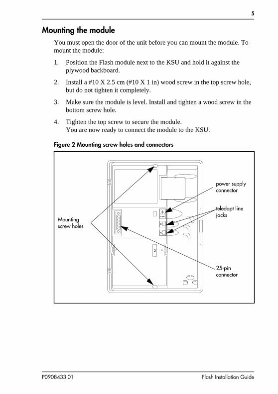
Mounting the moduleYou must open the door of the unit before you can mount the module. To mount the module:
1. Position the Flash module next to the KSU and hold it against the plywood backboard.
2. Install a #10 X 2.5 cm (#10 X 1 in) wood screw in the top screw hole, but do not tighten it completely.
3. Make sure the module is level. Install and tighten a wood screw in the bottom screw hole.
4. Tighten the top screw to secure the module.You are now ready to connect the module to the KSU.
Figure 2 Mounting screw holes and connectors
Mounting screw holes
power supply connector
teledapt line jacks
25-pin connector
P0908433 01 Flash Installation Guide

6
Figure 3 Installation overview
Connecting the module to the KSU Before you begin, ensure a Norstar station port is available at the distribution block and all line appearances are removed from the Flash DN(s) prior to booting the unit. For instructions on installing a station port and removing line appearances, refer to the Norstar Installation Guide that came with the Norstar KSU.
To connect the module:
1. Locate the distribution block.
2. Ensure there are available station ports at the distribution block. You need one station port for a two channel Flash and two station ports for a four channel Flash.
3. Mount the teladapt jack(s) next to the distribution block.
4. Use twisted pair station wire to connect each teladapt jack to a free station port in the distribution block.
5. Use a working Norstar telephone to test the port(s).
Flash Module
Feature
Norstar Modular KSU
Distribution Block
Cartridge
Power Supply
Flash Installation Guide P0908433 01

7
6. Connect one end of the teladapt cord to the station port at the side of the module. Connect the other end to the teladapt jack. If you have a four channel Flash, repeat this procedure for the second teladapt cord. Do not use a teladapt cord longer than 4.5 m (about 14 ft).
Installing the Feature CartridgeThe Flash Feature Cartridge is a PCMCIA ROM card that contains all the Flash Voice Mail Light, Flash Voice Mail or Flash ACD operating software and voice prompts.
To install the feature cartridge, insert the PCMCIA ROM card (Flash label up) into the slot provided on the Flash module. Refer to Figure 4 for more information.
Figure 4 Installing the Flash Feature Cartridge
P0908433 01 Flash Installation Guide
8
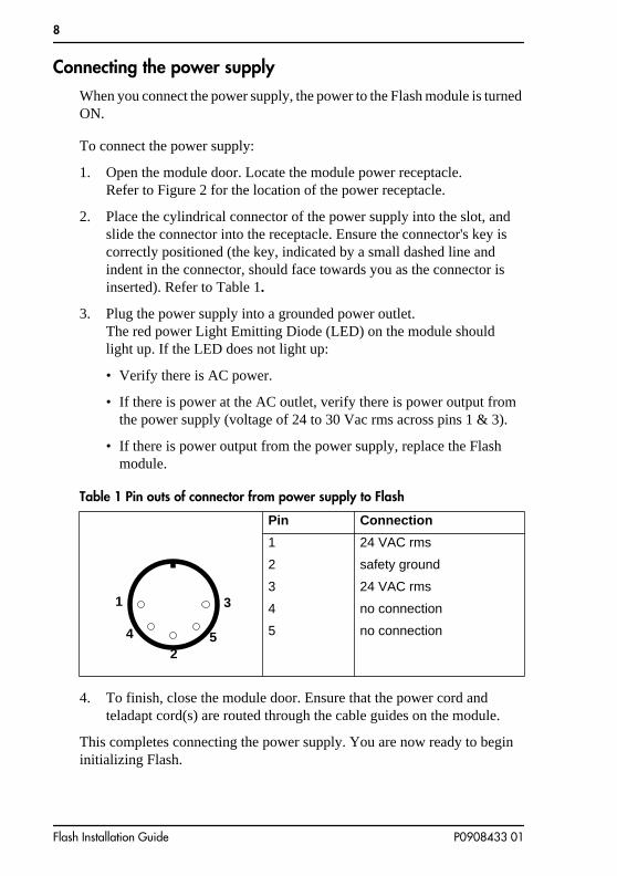
Connecting the power supplyWhen you connect the power supply, the power to the Flash module is turned ON.
To connect the power supply:
1. Open the module door. Locate the module power receptacle. Refer to Figure 2 for the location of the power receptacle.
2. Place the cylindrical connector of the power supply into the slot, and slide the connector into the receptacle. Ensure the connector's key is correctly positioned (the key, indicated by a small dashed line and indent in the connector, should face towards you as the connector is inserted). Refer to Table 1.
3. Plug the power supply into a grounded power outlet.The red power Light Emitting Diode (LED) on the module should light up. If the LED does not light up:
• Verify there is AC power.
• If there is power at the AC outlet, verify there is power output from the power supply (voltage of 24 to 30 Vac rms across pins 1 & 3).
• If there is power output from the power supply, replace the Flash module.
Table 1 Pin outs of connector from power supply to Flash
4. To finish, close the module door. Ensure that the power cord and teladapt cord(s) are routed through the cable guides on the module.
This completes connecting the power supply. You are now ready to begin initializing Flash.
Pin Connection
1 24 VAC rms
2 safety ground
3 24 VAC rms
4 no connection
5 no connection
1
4
2
3
5
Flash Installation Guide P0908433 01

9
Initializing Flash
When you initialize Flash, you are preparing the Flash software for use. You first initialize the Flash system and then you initialize:
• Flash Voice Mail Light or
• Flash Voice Mail or
• Flash ACD or
• both Flash Voice Mail and Flash ACD
Initializing the Flash system establishes:
• the mailbox number digit length matches the Norstar DN length
• the Feature Code range
Initializing Flash Voice Mail Light or Flash Voice Mail establishes:
• the primary and alternate languages of the Flash voice prompts
• if the Group List option is enabled
• the leading digit for Group Lists (if the Group List option is enabled)
Initializing Flash ACD establishes:
• the primary and alternate languages of the Flash voice prompts
This guide shows the steps to initialize Flash Voice Mail Light, Flash Voice Mail and Flash ACD. You only need to perform the steps required for the software installed.
Preparing FlashBefore you begin:
❏ Review the Flash Programming Record to determine and record the required programming settings for Flash Voice Mail Light and Flash Voice Mail.
❏ Review the Flash ACD Programming Record to determine and record the required programming settings for Flash ACD. The Flash ACD Programming Record is found in Appendix A of the Flash ACD Set Up and Operation Guide.
❏ Make sure you have a Norstar telephone with a two line display available.
P0908433 01 Flash Installation Guide
10
❏ Determine the Norstar KSU software version.
Determining the KSU software versionThe KSU software version must be compatible with Flash. For instructions about how to determine the KSU software version, refer to the Norstar Installation Guide for the KSU.
The KSU software version display uses a series of letters and numbers to denote the software version. For example, if the display shows SP: 30MUJ24
DR5 the version is DR5 9.24. Norstar uses letters of the alphabet to designate version numbers. The letter A represents 0, the letter B represents 1 and so on. The third character to the right of the colon (M) indicates the kind of KSU software and the next character (U) indicates the language combination of the KSU software.
Refer to Table 2 on page 11 to verify the compatibility of your KSU version with Flash.
Note: Flash ACD does not support KSUs or line cartridges that do not have Disconnect Supervision.
Flash Installation Guide P0908433 01

11
Table 2 KSU Software Version Compatibility
*These KSU software versions are compatible with Flash Voice Mail Light and Flash Voice Mail software only. They are not compatible with Flash ACD software.
All versions of CICS and MICS KSU software are compatible with:
• Flash Voice Mail Light software
• Flash Voice Mail software
• Flash ACD software
KSU Version SP Software Number
* Compact Disconnect Supervision English/French English/Spanish
SP: 30NSE05 DR5 or greaterSP: 30NYE05 DR5 or greater
* Compact Non-disconnect English/French English/Spanish
SP: 30MJJ21 DR5 or greaterSP: 30MKJ21 DR5 or greater
* Modular DR5 English/French English/Spanish
SP: 30MUL07 DR5 or greaterSP: 30MVL07 DR5 or greater
* Centrex + English/French English/Spanish
SP: 30MGJ22 DR5 or greaterSP: 30MHJ22 DR5 or greater
* 3X8 SP: 30NPE07 DR5 or greater
P0908433 01 Flash Installation Guide
12
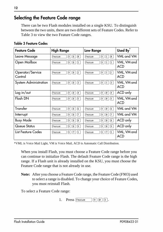
Selecting the Feature Code rangeThere can be two Flash modules installed on a single KSU. To distinguish between the two units, there are two different sets of Feature Codes. Refer to Table 3 to view the two Feature Code ranges.
Table 3 Feature Codes
When you install Flash, you must choose a Feature Code range before you can continue to initialize Flash. The default Feature Code range is the high range. If a Flash unit is already installed on the KSU, you must choose the Feature Code range that is not already in use.
Note: After you choose a Feature Code range, the Feature Code (F903) used to select a range is disabled. To change your choice of Feature Codes, you must reinstall Flash.
To select a Feature Code range:
Feature Code High Range Low Range Used By*
*VML is Voice Mail Light, VM is Voice Mail, ACD is Automatic Call Distribution.
Leave Message ƒ·°‚ ƒ·⁄‚ VML and VM
Open Mailbox ƒ·°⁄ ƒ·⁄⁄ VML, VM and ACD
Operator/Service Control
ƒ·°¤ ƒ·⁄¤ VML, VM and ACD
System Administration ƒ·°‹ ƒ·⁄‹ VML, VM and ACD
Log in/out ƒ·°› ƒ·‚› ACD only
Flash DN ƒ·°fi ƒ·‚fi VML, VM and ACD
Transfer ƒ·°fl ƒ·‚fl VML and VM
Interrupt ƒ·°‡ ƒ·‚‡ VML and VM
Busy Mode ƒ·°° ƒ·‚° ACD only
Queue Status ƒ·°· ƒ·‚· ACD only
List Feature Codes ƒ·•⁄ ƒ·•fi VML, VM and ACD
1. Press ƒ·‚‹.
Flash Installation Guide P0908433 01
13
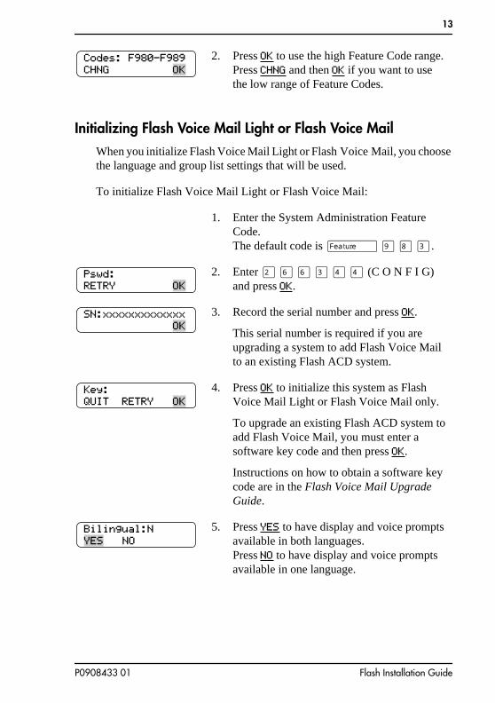
Initializing Flash Voice Mail Light or Flash Voice MailWhen you initialize Flash Voice Mail Light or Flash Voice Mail, you choose the language and group list settings that will be used.
To initialize Flash Voice Mail Light or Flash Voice Mail:
2. Press OK to use the high Feature Code range. Press CHNG and then OK if you want to use the low range of Feature Codes.
1. Enter the System Administration Feature Code. The default code is ƒ · ° ‹.
2. Enter ¤ fl fl ‹ › › (C O N F I G) and press OK.
3. Record the serial number and press OK.
This serial number is required if you are upgrading a system to add Flash Voice Mail to an existing Flash ACD system.
4. Press OK to initialize this system as Flash Voice Mail Light or Flash Voice Mail only.
To upgrade an existing Flash ACD system to add Flash Voice Mail, you must enter a software key code and then press OK.
Instructions on how to obtain a software key code are in the Flash Voice Mail Upgrade Guide.
5. Press YES to have display and voice prompts available in both languages.Press NO to have display and voice prompts available in one language.
Codes: F980-F989CHNG
Pswd:RETRY
SN:xxxxxxxxxxxxx
Key:QUIT RETRY
Bilingual:N NO
P0908433 01 Flash Installation Guide

14
6. Press ENG to use English as your primary language. Press FRE to use French as your primary language.Press SPA to use Spanish as your primary language.
Note: Only two of the three languages above will be available; English and either French or Spanish.
7. Press OK to enable Group Lists.
If Group Lists are not required, press CHNG. However, if you disable Group Lists, you must re-initialize Flash to re-enable Group Lists.
8. Press OK to enable the Leading Digit.
If 9 is not the leading digit for Group Lists, press CHNG and enter the new number. The Group List leading digit can be any number from 0 to 9. Special Mailbox numbers automatically begin with 1, so if you select a Group List leading digit of 1, the Special Mailboxes will begin with 2. The Group List Leading Digit cannot be the same as the first number of any other mailbox.
9. Press OK.
To return to Step 3, press RETRY.
When the initial configuration is completed, the display shows System Ready and Exit. The display then returns to the Norstar date and time.
Primary lang? FRE
Group lists?CHNG
Glist∫lead∫dig:9CHNG∫∫∫∫∫∫∫∫∫∫
System∫configRETRY∫∫∫∫∫∫∫∫∫
Configuring...
Flash Installation Guide P0908433 01

15
Table 4 System Coordinator mailbox number and default password
Determining the Flash Directory Number (DN)To determine the Flash DN:
Naming the Flash port
After the installation and initialization are completed, we recommend you use Norstar Configuration programming to rename the Norstar station port that Flash is connected to. We recommend you name the port FLASH.
For information about how to name the Flash DN, refer to the Norstar System Coordinator Guide.
Norstar DN length
Flash Voice Mail mailbox number length
System Coordinator mailbox and default password combination
2 2 120000
3 3 1020000
4 4 10020000
5 5 100020000
6 6 1000020000
7 7 10000020000
1. Enter the Flash DN Feature Code.The default code is ƒ · ° fi.
If you are using the low range of Feature Codes, press ƒ · ‚fi.
XX represents the Flash DN.
To end this Flash session, press OK or ®.
Set:XX
P0908433 01 Flash Installation Guide

16
Initializing Flash ACDTo initialize Flash ACD:
1. Enter the System Administration Feature Code. The default code is ƒ · ° ‹.
2. Enter ¤ fl fl ‹ › › (C O N F I G) and press OK.
3. Record the serial number and press OK.
This serial number is required if you are upgrading a system to add Flash ACD to an existing Flash Voice Mail system.
4. Press OK to initialize this system as Flash ACD only.
To upgrade a new or existing Flash Voice Mail system to add Flash ACD, you must enter a software key code and then press OK.
Instructions on how to obtain a software key code are in the Flash ACD Upgrade Guide.
5. Press YES to have display and voice prompts available in both languages.Press NO to have display and voice prompts available in one language.
6. Press ENG to use English as your primary language. Press FRE to use French as your primary language.Press SPA to use Spanish as your primary language.
Note: Only two of the three languages above will be available; English and either French or Spanish.
Pswd:RETRY
SN:xxxxxxxxxxxxx
Key:QUIT RETRY
Bilingual:N NO
Primary lang? FRE
Flash Installation Guide P0908433 01

17
Determining Flash Feature CodesThe Feature Codes for Flash are 980 through 989 or 904 through 913, inclusive. When these Feature Codes are used by other Norstar applications, Norstar assigns Feature Codes between 900 and 999 to Flash. These codes might not be assigned in sequential order. Record the assigned Feature Codes on Table 5 below.
Table 5 Assigned Feature Codes
7. Press OK.
To return to Step 3, press RETRY.
When the initial configuration is completed, the display shows System Ready and Exit. The display then returns to the Norstar date and time.
Feature Code name Number Used By*
*VML is Voice Mail Light, VM is Voice Mail, ACD is Automatic Call Distribution.
Leave Message Feature 9 ____ ____ VML and VM
Open Mailbox Feature 9 ____ ____ VML, VM and ACD
Operator/Service Control Feature 9 ____ ____ VML, VM and ACD
System Administration Feature 9 ____ ____ VML, VM and ACD
Log in/out Feature 9 ____ ____ ACD only
Flash DN Feature 9 ____ ____ VML, VM and ACD
Transfer Feature 9 ____ ____ VML and VM
Interrupt Feature 9 ____ ____ VML and VM
Busy Mode Feature 9 ____ ____ ACD only
Queue Status Feature 9 ____ ____ ACD only
System∫configRETRY∫∫∫∫∫∫∫∫∫
Configuring...
P0908433 01 Flash Installation Guide

18
To determine the Flash Feature Codes:
1. Press ƒ · • ⁄ on a Norstar M7310, M7324, or M7410 telephone.
If you are using the low range of feature codes, press ƒ · • fi.
2. Record the Feature Code for the first feature used by Flash in Table 5 above and on the Flash Programming Record or the Flash ACD Programming Record.
XX represents a number between 00 and 99.
Note: On Flash ACD only systems, the first feature used is Open mbox: F9XX.
3. Press NEXT to show the next Feature Code used by Flash. Record this code on the Flash Programming Record, and above in Table 5, “Assigned Feature Codes,” on page 17.
4. Repeat step 3 until you reach the final Flash Feature Code.
This is the final display if you are installing Flash ACD or Flash ACD and Flash Voice Mail.
This is the final display if you are installing Flash Voice Mail only.
Press ® to end this Flash session.
Leave msg: F9XX NEXT
Leave msg: F9XX
Q Status: F9XX QUIT
Interrupt: F9XX QUIT
Flash Installation Guide P0908433 01

19
Determining the Flash software versionTo determine the software version of the Flash module:
Maintenance RequiredMaintenance of the Flash installation is required if you attempt to initialize the system and the display shows:
If this occurs:
1. Check the wiring at the distribution block, then enter the System Administration Feature Code. The default code is ƒ · ° ‹.
The display should show:
2. If the display still shows Inactive feature, check that the Feature Code range has been chosen by pressing ƒ·‚‹.
1. Enter the System Administration Feature Code. The default code is ƒ · ° ‹.
2. Enter the System Coordinator mailbox number and password and press OK.
Refer to Table 4, “System Coordinator mailbox number and default password,” on page 15.
3. Press ·.
On Flash ACD only systems, the options on the second line of the display are ACD AA CCR.
4. Press ® to end this Flash session.
Log:QUIT RETRY
AdminMBOX AA OTHR
Flash∫x.x.xx OK
Inactive∫feature
Log:QUIT RETRY OK
P0908433 01 Flash Installation Guide

20
The display should show:
If the display above appears, choose a Feature Code range and then initialize Flash Voice Mail Light, Flash Voice Mail or Flash ACD using the procedure described earlier in this guide.
3. If the display still shows Inactive feature, disconnect the power cord and check all the wiring for the Flash module. Make sure the:
• power supply is connected and plugged in
• Flash module has had the necessary time to complete the four minute self testing procedure
• Flash module is connected to a working station port
• there are no telephones or peripherals connected to the station port which has the same DN that was assigned as the Control DN of an ACD queue.
• power source to the Flash module is not damaged
4. After checking all the wiring, reconnect the power. Wait four minutes and repeat steps 1 and 2.
5. If you have checked the wiring and the module is still not operational, unmount and repackage the module, and return it to your distributor.
Flash DN lengthFor Flash to work properly, the mailbox number length must match the Norstar KSU DN length. When you change the KSU DN length, the Flash system automatically reboots itself. Once the system completes its reboot, you must re-initialize and reprogram Flash. For more information about the KSU DN length, refer to the Norstar Installation Guide that came with your system.
Codes: F980-F989CHNG
Flash Installation Guide P0908433 01

21
Connecting a wallboard to the Flash module
Connecting and using a wallboard to display call activity is optional if you have Flash ACD. Before you install the wallboard, make sure you have an RS-232 cable.
Note: Use these same steps to connect another real-time status device such as a PC to the Flash module.
Important: The Flash module serial port is a standard RS-232 connector. Make sure you use an appropriately constructed cable to connect the wallboard to the Flash module.
Wallboard check listThe following wallboard specifications must be met before you connect the wallboard:
❏ wallboard speeds must support 1200 baud
❏ hardware and software compatibilityNote: Flash supports XON/XOFF.
❏ cable type must be straight through (modem cable)
Connecting the wallboardYou must open the door of the unit before you can connect the wallboard. To connect a wallboard:
1. Plug the male end of the RS-232 cable into the RS-232 port of the Flash module.
2. Plug the female end of the DB-9 cable into the female 9 pin RS-232 connector on the RS-232/RS-485 Converter box, using a DB-9 to DB-9 male adapter.
3. Connect one end of the 4 conductor cable with the line filter (that is supplied with the converter box) to the RS-485 connector on the RS-232/RS-485 Converter box.
4. Connect the other end of the 4 conductor cable to the RS-485 connector (labelled RS-232 in/RS-485 in) on the wallboard.
5. Turn on the wallboard.
P0908433 01 Flash Installation Guide
22
6. To select the type of wallboard you are using as the Real Time status device, refer to the Flash ACD Set Up and Operation Guide.
Note: The current version of Flash ACD supports wallboards that are manufactured by Spectrum Corporation. For more information about the wallboard, refer to the Spectrum Corporation documentation.
Flash Installation Guide P0908433 01
23
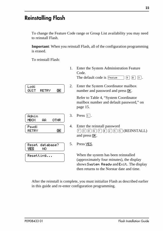
Reinstalling Flash
To change the Feature Code range or Group List availability you may need to reinstall Flash.
Important: When you reinstall Flash, all of the configuration programming is erased.
To reinstall Flash:
After the reinstall is complete, you must initialize Flash as described earlier in this guide and re-enter configuration programming.
1. Enter the System Administration Feature Code. The default code is ƒ · ° ‹.
2. Enter the System Coordinator mailbox number and password and press OK.
Refer to Table 4, “System Coordinator mailbox number and default password,” on page 15.
3. Press ⁄.
4. Enter the reinstall password ‡‹›fl‡°¤fifi (REINSTALL) and press OK.
5. Press YES.
When the system has been reinstalled (approximately four minutes), the display shows System Ready and Exit. The display then returns to the Norstar date and time.
Log:QUIT RETRY
AdminMBOX AA OTHR
Pswd:RETRY
Reset database? NO
Resetting...
P0908433 01 Flash Installation Guide

24
Flash Installation Guide P0908433 01

Appendix A: Upgrading to Flash
If you are upgrading from another Voice Mail or ACD system to Flash, the codes from the other software may still be stored in the KSU. You must remove the old codes using the External Feature Inquiry utility before installing a Flash module.
From a Norstar M7310, M7324 or M7410 telephone:
1. Press ƒ••ÙÏʉÍÊwhich is the same asPress ƒ••·‹°‹‡°
2. Enter <the Installer password>The default password is CONFIG (266344). For more information about the Installer password, refer to the Norstar Installer Guide that came with your KSU.
Access denied appears if you cannot use external feature inquiry from your telephone. In use: appears if someone else is using external feature inquiry, or an external feature is requesting an external feature access code.
3. Press FIRSTThe first Feature Code appears.
4. Press TEST.
9XX is the Feature Code.xxxxxxxx is a number assigned to the Feature Code.
5. Press REMOVE to remove the unused code.
If F9XX: Active appears, the code is still being used by a Norstar peripheral. Press OK.
6. Press NEXT to show the next Feature Code.
Password: RETRY
Feat∫code:∫∫∫∫∫∫FIRST∫EXIT
F9XX: xxxxxxxxTEST∫∫BACK∫ NEXT
F9XX: InactiveREMOVE∫ OK
F9XX: FreeTEST∫∫BACK∫ NEXT
P0908433 01 Flash Installation Guide

26
You are now ready to install the Flash module. Refer to Installing the module earlier in this guide.
7. Repeat steps 4 to 6 until you have tested all of the Feature Codes.
Note: If None Registered appears, all of the Feature Codes have been tested and removed. The External Feature Inquiry utility exits.
8. Press ® to exit the External Feature Inquiry utility.
F9XX: xxxxxxxxTEST∫∫BACK∫ NEXT
Flash Installation Guide P0908433 01

27
Index
AAlternate language, 9Anti-static grounding strap, 2Automatic Call Distribution (ACD),
initializing, 16
BB1 and B2 channels, 1Backboard, 2, 5
CCautions
Electrical, 3Water damage, 3
Channels, 1Channels, voice, 1Compatibility, KSU, 11Connecting to the KSU, 6
DDetermining
Feature Codes, 17KSU software version, 10Software version, 19
Directory Number (DN), 15Distribution block, 6DN length, 15
EElectrical requirements, 3Electromagnetic interference, 3Environment, conditions, 3
FFeature Codes, 17
determining, 17selecting, 12
Flash Directory Number (DN), 15Flash models, 1
P0908433 01
Flash, initializing, 9Flash, naming, 15Flash, reinstalling, 23Flash, upgrading, 25
GGroup Lists, 9, 14
HHumidity, 3
IInitializing, 9
Flash ACD, 16Flash Voice Mail, 13Flash Voice Mail Light, 13
Installation, 5Connecting power supply, 8Mounting, 5
Installation area, 3Installation overview, 6
KKSU Software Compatibility, 11KSU software version, 10KSU, connecting to, 6
LLanguage, alternate, 9
MMailbox number length, 9Models of Flash, 1
NNaming Flash, 15Norstar DN length, 15
OOverview, installation, 6
Flash Installation Guide
28
PPlywood backboard, 2, 5Port, naming, 15Ports vs channels, 1Ports, voice, 1Power supply, 8Prerequisites, 2Printer, 2
RReinstalling Flash, 23RS-232 terminal, 2
SScrews, 2Software version, 19Special parts, 2Station port, 1Surge protector, 2
TTerminal, RS-232, 2
UUpgrading to Flash, 25
VVoice channels, 1Voice Mail Light, initializing, 13Voice Mail, initializing, 13Voice ports, 1
WWallboard, 21Wood screws, 2
Flash Installation Guide P0908433 01