flc and plc based process optimization and … and plc based process optimization and control of...
TRANSCRIPT

Research Journal of Engineering Sciences ___________________________________________ ISSN 2278 – 9472
Vol. 1(2), 51-62, August (2012) Res. J. Engineering Sci.
International Science Congress Association 51
FLC and PLC based Process Optimization and Control of Batch Digester
in Pulp and Paper Mill
Singh Rana Dinesh Department of Instrumentation, Kurukshetra University, Kurukshetra, INDIA
Available online at: www.isca.in Received 20th August 2012, revised 23rd August 2012, accepted 24th August 2012
Abstract
Optimization and control of a batch digester operation is necessary to improve the quality of pulp produced in the pulp and
paper mill. The process involves controlling all the phases of the entire cooking cycle. Pulp and paper process is nonlinear
and non stationary in nature. In such type of process it is difficult to derive and identify an appropriate dynamic model for
traditional controllers due to less reliability of mathematical model of the process. So instead of conventional or advanced
controller which totally depends on mathematical model of process, a fuzzy logic control strategy has been proven better
option for controlling such processes. This scheme of control will evaluate certainty within uncertainty and handling the
parameters within range of control the entire process continuously through fluctuations occurs. In present paper,
programmable logic controller (PLC) and a fuzzy logic controller (FLC) based schemes for automation and control of pulp
and paper mill batch digester has been purposed and implemented which show consistent results. The system design starts
from identification of inputs, outputs and choosing the membership function for each condition from normal operation up to
emergency operation of pulp and paper mill batch digester. PLC provides control of pulp digesters for the process of making
pulp from wood chips. PLC are used to calculate and control the amount of chips, based on density and the digester volume;
determine the quantity of cooking liquors and add the required amounts in sequence. Programmable controllers also control
temperature till cooking is completed. Rs logic 500 based SLC 500 processors [CPU 1747-120 C/F] produces better
stabilize and optimize operation of batch digester.
Keywords: Fuzzification, Inference engine, defuzzification, PLC, FLC, MSF, ladder diagram.
Introduction
Paper industry in India is the 15th
largest paper industry in the
world. The government regards the paper industry as one of the
35 high priority industries of the country which generating more
than 1.3 million employment through agricultural activities
directly and indirectly1. The pulp and paper industries in India
have been categorized into large-scale and small-scale. Those
paper industries, which have capacity above 24,000 tons per
annum, are designated as large-scale paper industries. Pulp and
paper are manufactured from raw materials which containing
cellulose fibers2, generally wood, recycled paper, and
agricultural residues. Cellulose fibers originate from nonwood
raw materials such as bagasse (sugar cane fibers), cereal straw,
bamboo, reeds, esparto grass, jute, flax, and sisal. The main
steps in pulp and paper manufacturing are raw material
preparation, such as wood debarking and chip making, pulp
manufacturing, pulp bleaching, paper manufacturing and fiber
recycling. Pulp and paper mills may exist separately or as
integrated operations. Manufactured pulp is used as a source of
cellulose for fiber manufacture and for conversion into paper or
cardboard. The manufacture of pulp for paper and cardboard
employs mechanical, thermo mechanical, chemimechanical, and
chemical methods. Mechanical pulping separates fibers by such
methods as disk abrasion and billeting. Chemical pulps are
made by cooking (digesting) the raw materials, using the Kraft
(sulfate) and sulfite processes. Kraft processes produce a variety
of pulps used mainly for packaging and high-strength papers
and board. Wood chips are cooked with caustic soda to produce
brown stock, which is then washed with water to remove
cooking (black) liquor for the recovery of chemicals and energy.
In the case of chemical pulps (Kraft and sulfite), the objective of
bleaching is to remove the small fraction of the lignin remaining
after cooking so that fibers are free and can be easily molded to
the required characteristics. An alkali, such as sodium
hydroxide, is necessary in the bleaching process to extract the
alkali-soluble form of lignin. Pulp is washed with water in the
bleaching process.
Although chemical pulping digestion processes have been
widely applied in paper industry but the effective control of
such processes is still an unsolvable problem. Wood chip quality
variations, measurement of physical parameters problems and
long process time delay make the process control difficult due to
less reliability of mathematical model of such processes.
Conventional controller such as PID can not be effectively used
in batch processes because of its nonlinear and non stationary
nature. The prime objective of the present work is to investigate
and implement FLC and PLC based intelligent process control
techniques to automate and optimize the batch digestion
processes in pulp and paper industrial applications. The Fuzzy
control is emerging as a technology that can enhance the
capabilities of industrial automation and is suitable for control
level tasks generally performed in programmable controllers
Research Journal of Engineering Sciences________________________________________________________ ISSN 2278 – 9472
Vol. 1(2), 51-62, August (2012) Res. J. Engineering Sci.
International Science Congress Association 52
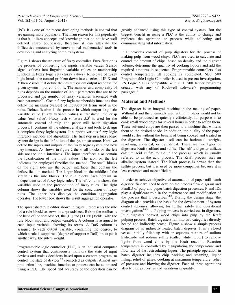
(PC). It is one of the recent developing methods in control that
are gaining more popularity. The main reason for this popularity
is that it utilizes concepts and knowledge that do not have well
defined sharp boundaries; therefore it can alleviate the
difficulties encountered by conventional mathematical tools in
developing and analyzing complex systems.
Figure 1 shows the structure of fuzzy controller. Fuzzification is
the process of converting the inputs variable values (sensor
signal values) into linguistic variable values or membership
function in fuzzy logic sets (fuzzy values). Rule-base of fuzzy
logic breaks the control problem down into a series of IF X and
Y then Z rules that define the desired system output response for
given system input conditions. The number and complexity of
rules depends on the number of input parameters that are to be
processed and the number of fuzzy variables associated with
each parameter3-5
. Create fuzzy logic membership functions that
define the meaning (values) of input/output terms used in the
rules. Defuzzification is the process in which output linguistic
variable value (fuzzy variable value) is translated into crisp
value (real value). Fuzzy tech software 5.56 is used for the
automatic control of pulp and paper mill batch digestion
process. It contains all the editors, analyzers and tools to design
a complete fuzzy logic system. It supports various fuzzy logic
inference methods and algorithms. The first step in a fuzzy logic
system design is the definition of the system structure. Here, we
define the inputs and outputs of the fuzzy logic system and how
they interact. As shown in figure 2 the small blocks on the left
side are the input interfaces. The input interfaces also contain
the fuzzification of the input values. The icon on the left
indicates the employed fuzzification method. The small blocks
on the right side are the output interfaces that contain the
defuzzification method. The larger block in the middle of the
screen is the rule blocks. The rule blocks each contain an
independent set of fuzzy logic rules. The left column shows the
variables used in the precondition of fuzzy rules. The right
column shows the variables used for the conclusion of fuzzy
rules. The upper box displays the condition aggregation
operator. The lower box shows the result aggregation operator.
The spreadsheet rule editor shown in figure 3 represents the rule
(of a rule block) as rows in a spreadsheet. Below the toolbar is
the head of the spreadsheet, the [IF] and [THEN] fields, with the
rule block input and output variables. A column is assigned to
each input variable, showing its terms. A DoS column is
assigned to each output variable, containing the degree, to
which a rule is supported (degree of support = DoS) or, to put it
another way, the rule’s weight.
Programmable logic controller (PLC) is an industrial computer
control system that continuously monitors the state of input
devices and makes decisions based upon a custom program, to
control the state of devices7-9
connected as outputs. Almost any
production line, machine function or process can be automated
using a PLC. The speed and accuracy of the operation can be
greatly enhanced using this type of control system. But the
biggest benefit in using a PLC is the ability to change and
replicate the operation or process while collecting and
communicating vital information.
PLC provides control of pulp digesters for the process of
making pulp from wood chips. PLCs are used to calculate and
control the amount of chips, based on density and the digester
volume; determine the quantity of cooking liquors and add the
required amounts in sequence. Programmable controllers also
control temperature till cooking is completed. SLC 500
Programmable Logic Controller is used in present investigation.
RS Logic 500 is compatible with SLC 500 ladder programs
created with any of Rockwell software’s programming
packages10
.
Material and Methods
The digester is an integral machine in the making of paper.
Without it and the chemicals used within it, paper would not be
able to be produced as quickly / efficiently. Its purpose is to
cook small wood chips for several hours in order to soften them.
These softened chips are then passed to a machine that whitens
them to the desired shade. In addition, the quality of the paper
would suffer without the benefit of being cooked and treated in
the digester. The digester itself can be horizontal, upright,
revolving, spherical, or cylindrical. There are two types of
digesters: Kraft (sulfate) and sulfite. The sulfite digester utilizes
calcium acid sulfite to aid in the process, which is usually
referred to as the acid process. The Kraft process uses an
alkaline system instead. The Kraft process is newer than the
sulfite process, but it is used by more companies because it is
less corrosive and more efficient.
In order to achieve objective of automation of paper mill batch
digester, first we need to develop the process flow diagram and
PandID of pulp and paper batch digestion processes. P and IDs
play a significant role in the maintenance and modification of
the process that it describes3,4,9
. During the design stage, the
diagram also provides the basis for the development of system
control schemes, allowing for further safety and operational
investigations3,4,9,11
. Pulping process is carried out in digesters.
Pulp digesters convert wood chips into pulp by the Kraft
pulping process. Batch digesters fall into two categories directly
heated and indirectly heated. Figure 4 show a simple process
diagram of an indirectly heated batch digester. It is a closed
vessel initially filled up with an aqueous mixture of sodium
hydroxide and sodium sulfite (called white liquor) to remove
lignin from wood chips by the Kraft reaction. Reaction
temperature is controlled by manipulating the temperature and
flow rate of the recirculating liquor. The principle operation in
batch digester includes chip packing and steaming, liquor
filling, relief of gases, cooking at maximum temperature, relief
of pressure and blowing the digester. Each of these operations
affects pulp properties and variations in quality.

Research Journal of Engineering Sciences___________
Vol. 1(2), 51-62, August (2012)
International Science Congress Association
Text block explaining object of Fuzzy control system
Rule Block Properties: Operators Dialog
Schematic Flow
_________________________________________________
International Science Congress Association
Figure-1
Structure of a fuzzy controller
Figure-2
Text block explaining object of Fuzzy control system
Figure-3
Rule Block Properties: Operators Dialog
Figure-4
Schematic Flow Diagram of the Batch Pulp Digester
_____________ ISSN 2278 – 9472
Res. J. Engineering Sci.
53

Research Journal of Engineering Sciences________________________________________________________ ISSN 2278 – 9472
Vol. 1(2), 51-62, August (2012) Res. J. Engineering Sci.
International Science Congress Association 54
The figure 5 shows the Pand ID of pulp and paper mill batch
digester. A batch digester can be heated in two different ways,
by direct steaming or by indirect heating with forced circulation.
In direct heating method, steam is injected through a valve in
the bottom of digester. The difference in temperature between
top and bottom makes the liquor circulate by convection, and
hot liquor rises through the middle of digester, while colder
liquor at the top flows down the walls to the bottom where it
meets the hot steam and is reheated. Indirect heating includes a
circulation system with pump, an external heat exchanger, and
strainer plates in the middle section. The liquor is heated in a
heat exchanger where the heating medium is steam that
condenses. The hot liquor is then returned to the top and bottom
of the digester. Indirect heating with forced liquor circulation
avoids liquor dilution and a more uniform temperature profile
throughout the digester is achieved. The liquor is normally
introduced to digester at about 700C. Heating time varies from
30 to 120 minutes. Maximum temperature reached ranges from
1600C to 180
0C. During heating and cooking, gases are formed.
Remaining air and other non condensable gases, such as CO2,
which is released in the cooking reactions, also accumulate.
These gases must be removed from the digester otherwise
digester pressure will be higher than the steam pressure
corresponding to liquor temperature. This “false pressure” can
be lead to problem with cooking control. When predetermined
cooking time is reached, partial pressure released by operating
the gas relief valve and releasing gases. Once the digester has
reached blowing pressure, the bottom valve is opened and
content is blown in the blow tank.
The figure 6 shows the schematic of digester
control/optimization. In charging phase of digester it is
necessary to monitor the weight of wood chip being fed into
along with its moisture. This enables us to determine the OD
weight of wood chips being fed. The OD weight decides the
amount of liquor to be used for cooking in digesters. Addition of
liquor is usually done in a particular ratio called the liquor wood
ratio. The cooking phase is the most important phase where end
of the cook is to be determined accurately so that any over or
under cooking of the pulp is avoided thereby resulting in good
quality pulp and minimizing the wastage of raw materials. The
parameters that must be maintained carefully during cooking are
effective alkali concentration of the cooking liquor, liquor
quantity, digester temperature and digester pressure. Cooking
reactions start when chips reach the cooking temperature, about
150 - 170oC, depending on the wood species and grade
requirements. The active chemicals of the cooking liquor react
with lignin in chips and convert it chemically into the
compounds that dissolve in the cooking liquor. Fibers are
separated into the mass since the bonding material of the chips
is dissolved.
Design and developed fuzzy logic controller based scheme for
automation of pulp and paper mill batch digester have been
illustrated in figure 7. As shown in figure 7, there are inputs to
fuzzy controller namely wood chip, moisture, liquor,
temperature, pressure and outputs namely odweight, pulp,
lignin, pulp blow. Valves are used to control the tempreture,
pressure and pulp flow.
Figure-5
Pand ID of pulp and paper mill batch digester

Research Journal of Engineering Sciences________________________________________________________ ISSN 2278 – 9472
Vol. 1(2), 51-62, August (2012) Res. J. Engineering Sci.
International Science Congress Association 55
Figure-6
Digester Control/Optimization
Figure-7
Fuzzy Logic Controller for batch digester

Research Journal of Engineering Sciences________________________________________________________ ISSN 2278 – 9472
Vol. 1(2), 51-62, August (2012) Res. J. Engineering Sci.
International Science Congress Association 56
Figure-8
Fuzzy logic controller for step 1
The control loops for various steps are defined as: For Step-
1: Fuzzy controller for step1 is shown in figure 8. The IF-THEN
rules for step 1 are: IF chip and moisture THEN Valve1, IF OD
Weight and white liquor THEN valve2, IF Moisture and
Valve1 THEN OD Weight, IF valve2 and white liquor THEN
wood chip
In step 1, valve 1 controls the quantity of chip fed into the
digester. Control parameters are chip and moisture. To monitor
the weight of chip along with moisture, OD weight is determine.
In batch pulping process, wood chip and cooking liquor are
loaded into a digester which is then closed. So valve 2 is used to
control the concentration of woodchip and liquor. Chemical of
cooking liquor react with the lignin which binds the fibers
together and the lignin is dissolved. The membership function
(MSF) of various parameter of step 1 are illustrated in figures
9-15.The rule editor for wood chip is shown in table 1.
Figure-9
MSF for Chip
Figure-10
MSF for Moisture
Figure-11
MSF for Valve 1
Figure-12
MSF for odweight
Figure-13
MSF for white liquor
Figure-14
MSF for woodchip
Research Journal of Engineering Sciences________________________________________________________ ISSN 2278 – 9472
Vol. 1(2), 51-62, August (2012) Res. J. Engineering Sci.
International Science Congress Association 57
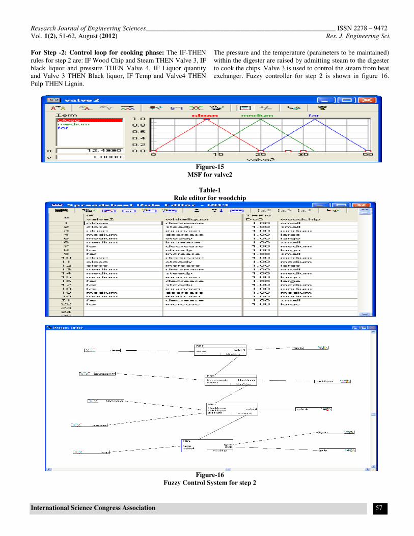
For Step -2: Control loop for cooking phase: The IF-THEN
rules for step 2 are: IF Wood Chip and Steam THEN Valve 3, IF
black liquor and pressure THEN Valve 4, IF Liquor quantity
and Valve 3 THEN Black liquor, IF Temp and Valve4 THEN
Pulp THEN Lignin.
The pressure and the temperature (parameters to be maintained)
within the digester are raised by admitting steam to the digester
to cook the chips. Valve 3 is used to control the steam from heat
exchanger. Fuzzy controller for step 2 is shown in figure 16.
Figure-15
MSF for valve2
Table-1
Rule editor for woodchip
Figure-16
Fuzzy Control System for step 2

Research Journal of Engineering Sciences________________________________________________________ ISSN 2278 – 9472
Vol. 1(2), 51-62, August (2012) Res. J. Engineering Sci.
International Science Congress Association 58
The membership function (MSF) of various parameter of step 2
are illustrated in figures 17-25. IF –THEN rule block for pulp
and lignin are tabulated in table 2.
Figure-17
MSF for Steam
Figure-18
MSF for valve 3
Figure-19
MSF for liquor quantity
Figure-20
MSF for black liquor
Figure-21
MSF for pressure
Figure-22
MSF for valve 4
Figure-23
MSF for Temperature
Figure-24
MSF for pulp
Figure-25
MSF for Lignin
Table-2
Rule editor for Pulp and lignin

Research Journal of Engineering Sciences________________________________________________________ ISSN 2278 – 9472
Vol. 1(2), 51-62, August (2012) Res. J. Engineering Sci.
International Science Congress Association 59
Figure-26
Fuzzy control for Step 3
For Step-3: In blow phase pulp without lignin are blow in other
tank by pump and valve 5 controls the blow of pulp in tank. So
parameter of that is level tank and pulp. The IF-THEN rule for
step 3 is: IF level tank and pulp THEN Pulp Blow THEN Valve
5. Fuzzy control for step 3 is illustrated in figure 26 in which
level tank and pulp are the input parameters. These parameters
are controlled by rule table. Pulp blow and valve 5 are the
output parameters. Valve 5 is used to control the pulp and level
tank.
The membership function (MSF) of various parameter of step 2
are illustrated in figures 27-29. Figure 30 shows the interactive
debug mode for pulp blow and valve 5.
Figure-27
MSF for level tank
Figure-28
MSF for pulp blow
Figure-29
MSF for valve 5
Figure-30
Interactive debug mode for pulp blow and valve5
Results and Discussion
Step 1: The Fuzzy logic system made for step 1 is made for
controlling the liquor wood ratio. Liquor wood ratio is measured
by controlling the flow of wood chip. Here OD weight of chip is
monitored and controlled. The chips are pre-impregnated and
preheated black liquor to make batch cooking more energy
efficient. The cooking liquor is circulated from the middle to top
and bottom to ensure a uniform cooking. Figure 31 shows the
Time Plot and figure 32 shows the 3D Plot of charging phase of
pulp and paper mill digester plotted between weight of wood
chip, its moisture as input and OD weight as output. It infers
from the time plot that variations of the parameter are agree
with rule table.
Figure-31
Time plot for od weight
Research Journal of Engineering Sciences________________________________________________________ ISSN 2278 – 9472
Vol. 1(2), 51-62, August (2012) Res. J. Engineering Sci.
International Science Congress Association 60
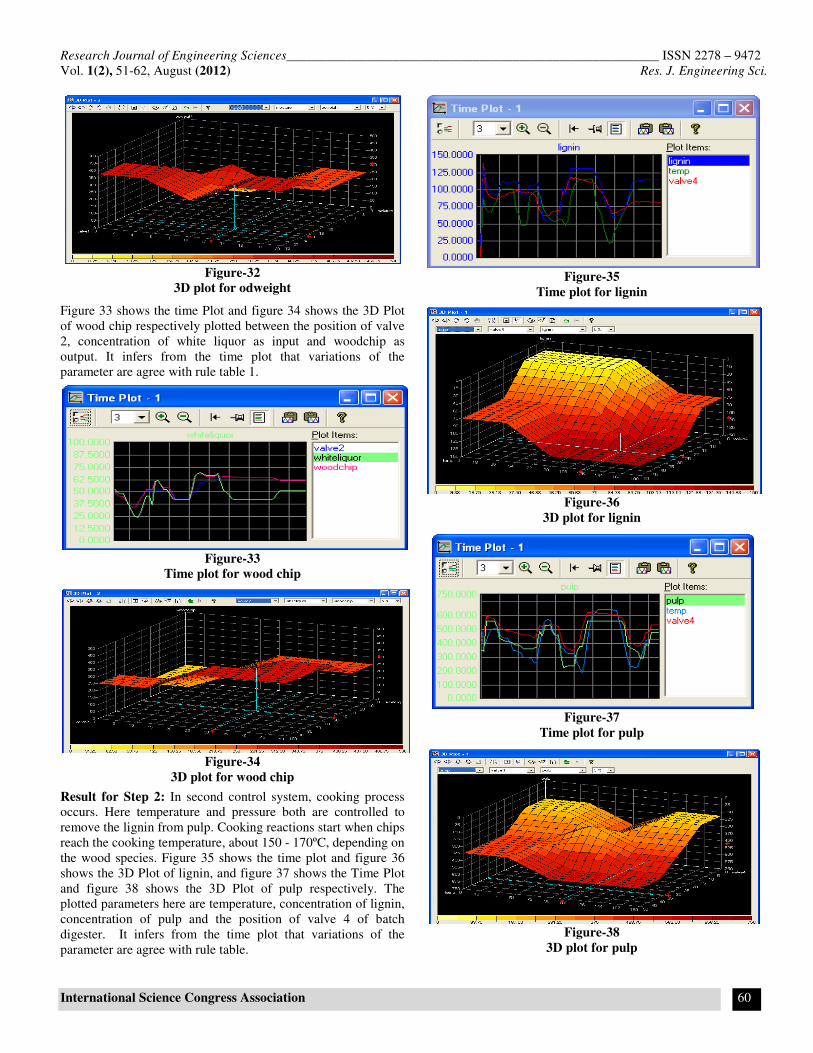
Figure-32
3D plot for odweight
Figure 33 shows the time Plot and figure 34 shows the 3D Plot
of wood chip respectively plotted between the position of valve
2, concentration of white liquor as input and woodchip as
output. It infers from the time plot that variations of the
parameter are agree with rule table 1.
Figure-33
Time plot for wood chip
Figure-34
3D plot for wood chip
Result for Step 2: In second control system, cooking process
occurs. Here temperature and pressure both are controlled to
remove the lignin from pulp. Cooking reactions start when chips
reach the cooking temperature, about 150 - 170ºC, depending on
the wood species. Figure 35 shows the time plot and figure 36
shows the 3D Plot of lignin, and figure 37 shows the Time Plot
and figure 38 shows the 3D Plot of pulp respectively. The
plotted parameters here are temperature, concentration of lignin,
concentration of pulp and the position of valve 4 of batch
digester. It infers from the time plot that variations of the
parameter are agree with rule table.
Figure-35
Time plot for lignin
Figure-36
3D plot for lignin
Figure-37
Time plot for pulp
Figure-38
3D plot for pulp

Research Journal of Engineering Sciences________________________________________________________ ISSN 2278 – 9472
Vol. 1(2), 51-62, August (2012) Res. J. Engineering Sci.
International Science Congress Association 61
Result for Step 3: In third control system, pulp is blowed from
tank which is controlled by valve 5. Figure 39 shows the Time
Plot and figure 40 shows the 3D Plot of pulpblow respectively.
The plotted parameters here are level of the tank, concentration
of pulp and quantity of pulpblow from the digester. It infers
from the time plot that variations of the parameter are agree
with rule table.
Figure-39
Time plot for pulpblow
Figure-40
3D plot for pulpblow
Simulation of Batch digester using PLC: PLC includes
development and design of various control loops for pulp and
paper mill digester control and simulates these rungs with help
of standard emulator (RS logic 500). Figure 41 illustrates the
ladder diagram for batch digester. This RS ladder program is
basically developed to control the temperature, pressure, liquor
and chip flow in processing of digester.
Conclusion
Present paper describes the investigation and implementation of
FLC and PLC based intelligent process control techniques to
automate and optimize the batch digestion processes in pulp and
paper mill applications. Fuzzy control system for the entire pulp
and paper mill batch digester has been designed with loop
identification, which shows consistent results as elaborate in
previous sections. It can infer from the present work that fuzzy
control system have been proven better option for controlling
the nonlinear and non stationary processes and least affected by
process modeling error. In addition expanded span with the
help of linguistic variables give better approach for production
with least errors. This shows high reliability of this process
control scheme. Designed FLC and PLC based process control
techniques are complete multi-level package to stabilize and
optimize the pulp and paper mill batch digester operation. The
functions at three stages provide safety handle automated chip
and liquor charging, steam ramping, and cook and blow
controls. It is the major conclusion from present work that the
Rs logic 500 based SLC 500 processors [CPU 1747-120 C/F]
produces better result for batch digester. The future up gradation
of present batch digester will not cost much because of
flexibility in programming of batch digester. PLC based
automated system have high processing capability and excellent
I/O systems for digital information.
References
1. Roy T.K., Overview of Indian Paper Industry, Workshop
on Adoption of Energy Efficient Process Technologies and
Energy Management Practices in Pulp and Paper Sector
under Energy Conservation Act 2001, Saharanpur,
February 14, (2007)
2. Pulp and Paper Mills Pollution Prevention and Abatement-
Handbook, World Bank Group, July (1998)
3. Rana Dinesh Singh and Sharma Rajiv, Fuzzy Logic Based
Automation of Green House Environmental parameters for
Agroindustries-A Simulation Approach, IJAER, 6(5), 662-
666 (2011)
4. Sharma Rajvir, Rana Dinesh Singh etal, A Fuzzy Logic
based Automatic Control of Rotary Crane (A Simulation
Approach), Advance Materials Research, 400(3-8), 4659-
4666(2012)
5. Behera Laxmidhar and Indrani Kar Intelligent systems and
controls, Principles and applications, Oxford University
Press (2009)
6. Fuzzy TECH reference manual, Inform Software
Corporation, GmbH (2001)
7. Krishnakant, Computer-based Industrial Control, PHI
Private Ltd, 492-500 (1998)
8. John W. Webb and Ronald A. Reis, Programmable Logic
Controllers, PHI Private Ltd (2003)
9. Bela. G.Liptak, Process Measurement and Analysis,
Butterworth-Heinemann an imprint of Elsevier (1995)
10. Rockwell software reference manual (2010)
11. Pathak Kushang, Fuzzy logic based Automation and
control of Carbon Dioxide filtration process, M.Tech
Dissertation, Kurukshetra University, Kurukshetra (2011)

Research Journal of Engineering Sciences________________________________________________________ ISSN 2278 – 9472
Vol. 1(2), 51-62, August (2012) Res. J. Engineering Sci.
International Science Congress Association 62
Figure -41
Ladder Diagram of Batch Digester