fleet series boilers - specifiedby
TRANSCRIPT

FLEET SERIES BOILERS
Floor Standing, Condensing , Fully Modulating, Pre-Mix,
Gas Fired Boilers for Heating & Domestic Hot Water Installations
Installation, Commissioning and Operating Instructions
Models: F40V, F50V, F60V, F70V, F85V,F100V
F125V & F150V
NATURAL GAS I2H
IMPORTANT NOTE
THESE INSTRUCTIONS MUST BE READ AND UNDERSTOOD BEFORE INSTALLING,
COMMISSIONING, OPERATING OR SERVICING EQUIPMENT

HAMWORTHY HEATING LTD
Page FLEET V Series
500001213/G
1 i
NOTE: THESE INSTRUCTIONS MUST BE READ AND UNDERSTOOD BEFORE INSTALLING, COMMISSIONING, OPERATING OR SERVICING EQUIPMENT. THE FLEET BOILER IS INTENDED FOR USE AS A COMMERCIAL APPLIANCE AND IS NOT CERTIFIED FOR USE IN DOMESTIC APPLICATIONS. THIS BOILER IS FOR USE ON GROUP H NATURAL GAS (2ND FAMILY) I2H PLEASE ENSURE RELEVANT INFORMATION REQUIRED WITHIN DOCUMENT IS FOUND BEFORE FIRING BOILER. COUNTRY OF DESTINATION : UNITED KINGDOM & REPUBLIC OF IRELAND THIS BOILER COMPLIES WITH ALL RELEVANT EUROPEAN DIRECTIVES. PRODUCT IDENTIFICATION No. 86CM36
PUBLICATION NO. 500001213 ISSUE ‘G’ NOVEMBER 2013
FLEET SERIES BOILERS
Floor Standing, Condensing , Fully Modulating, Pre-Mix,
Gas Fired Boilers for Heating & Domestic Hot Water Installations
Installation, Commissioning and Operating Instructions
Models: F40V, F50V, F60V, F70V, F85V, F100V,
F125V & F150V
NATURAL GAS I2H

HAMWORTHY HEATING LTD
Page FLEET V Series
500001213/G
2 ii
CONTENTS PAGE 1.0 INTRODUCTION ................................................................................................................................ 1 2.0 SUPPLY AND DELIVERY ................................................................................................................. 2 3.0 SIZE AND SPACE REQUIREMENTS ............................................................................................... 4 4.0 SITE LOCATION AND PREPARATION ............................................................................................ 7 4.1 Site Location 4.2 Gas Supply 4.3 Flue System 4.4 Water Supply 4.5 Condensate Connections 4.6 Electrical Supply 5.0 BOILER ASSEMBLY ....................................................................................................................... 12 5.1 General 5.2 Water Connections 5.3 Flue Connections 5.4 Electrical Connections 6.0 PRE-COMMISSIONING ................................................................................................................... 13 6.1 Gas Supply 6.2 Ventilation 6.3 Pipework, Valves and Pump 6.4 Flue 6.5 Electrical 7.0 CHECKS PRIOR TO LIGHTING ...................................................................................................... 14 7.1 Boiler Gas System Leak Check 7.2 Checks Prior to Lighting the Boiler 7.3 Initial Lighting 7.4 Combustion Checks 7.5 User Instructions 8.0 BOILER CONTROLS ....................................................................................................................... 18 8.2 Controls Operation 8.3 Functions 9.0 FAULT FINDING .............................................................................................................................. 34 10.0 SERVICING ...................................................................................................................................... 36 11.0 REPLACEMENT OF FAILED COMPONENTS ............................................................................... 38 12.0 RECOMMENDED SPARES ............................................................................................................. 39

HAMWORTHY HEATING LTD
Page FLEET V Series
500001213/G
3 iii
PAGE APPENDICES
APPENDIX A GAS DATA ............................................................................................................................. 43 APPENDIX B ELECTRICAL CONNECTIONS AND CONTROLS ............................................................... 44 APPENDIX C FLUE DATA ........................................................................................................................... 47 APPENDIX D VENTILATION........................................................................................................................ 50 APPENDIX E WATER DATA ....................................................................................................................... 51 APPENDIX F HYDRAULIC DIAGRAMS - CASCADE CONTROL ............................................................. 56
PICTORIAL AND DIAGRAMATICAL DATA Figure 2.1 Boiler Packaging ...................................................................................................................... 2 Figure 2.2 Boiler Package Dimensions ..................................................................................................... 3 Figure 3.1.1 Dimensions and clearances ..................................................................................................... 4 Figure 3.1.2 Table dimensions and clearances ..................... ...................................................................... 5 Figure 3.2.1 Dimensions F40/F100V 2 high installation pipe work kit ......................................................... 5 Figure 3.2.2 Dimensions F125/F150V 3 high installation pipe work kit ....................................................... 6 Figure 4.2 Gas connection ........................................................................................................................ 7 Figure 4.4 Water connections .................................................................................................................... 9 Figure 4.5.1 Boiler condensate connection ................................................................................................ 12 Figure 4.6 Wiring schematic .................................................................................................................... 13 Figure 7.1 Gas system leak check .......................................................................................................... 16 Figure 7.2.2 Gas inlet pressure test point ................................................................................................... 17 Figure 7.2.1 On / OFF Switch ..................................................................................................................... 18 Figure 7.6 Combustion analyser probe position ...................................................................................... 18 Figure 7.6.1 Adjusting gas valve throttle .................................................................................................... 19 Figure 7.6.2 Adjusting gas valve throttle .................................................................................................... 19 Figure 7.6.3 Adjusting gas valve offset ....................................................................................................... 19 Figure 7.6.4 Adjusting gas valve offset ....................................................................................................... 19 Figure 8.2 System configuration with LMU .............................................................................................. 20 Figure 8.2.1.1 Fascia Legend ........................................................................................................................ 21 Figure 8.2.1.2 Overview of fascia panel ........................................................................................................ 21 Figure 8.1.6 General overview of boiler controls ........................................................................................ 22 Figure 8.2.1.2 Info display parameters .......................................................................................................... 24 Figure 8.2.1.3 Operation and display philosophy .......................................................................................... 25 Figure 8.2.2 Screen legend ........................................................................................................................ 26 Figure 8.2.3.1 Default display ........................................................................................................................ 27 Figure 8.2.3.2 Display of status codes ........................................................................................................... 27 Figure 8.2.4 Lockout display ....................................................................................................................... 28 Figure 8.2.5 Heating circuit setpoint ........................................................................................................... 28 Figure 8.2.6 Overview of end user parameters .......................................................................................... 29 Figure 8.2.9 Operating mode ...................................................................................................................... 30 Figure 8.2.10 LMU Error codes .................................................................................................................... 32 Figure 8.3.10 LMU Error log ......................................................................................................................... 33 Figure 8.3.11 Operating phases ................................................................................................................... 34 Figure 8.3.12 Operating phases ................................................................................................................... 35 Figure 9.2 Water flow switch ................................................................................................................... 36 Figure 9.3.1 Wiring Schematic ................................................................................................................... 37 Figure 10.2 Combustion chamber ............................................................................................................. 39 Figure 10.2.1 Spark electrode position ......................................................................................................... 39 Figure 10.2.2 Flame sensing probe position ................................................................................................ 39

HAMWORTHY HEATING LTD
Page FLEET V Series
500001213/G
4 iv
APPENDIX PAGE Figure A1 Gas Data ................................................................................................................................ 43 Figure B1.1 Electrical Supply ..................................................................................................................... 44 Figure B1.2 External Control Wiring for Multiple Boiler Installation ........................................................... 45 Figure B1.3 Sensor resistance values ....................................................................................................... 46 Figure C1 Flue Data ................................................................................................................................ 47 Figure C6.1 Flue equivalent lengths .......................................................................................................... 49 Figure C6.2 Flue Accessories .................................................................................................................... 49 Figure D1 Mechanical Ventilation Flow Rates ........................................................................................ 50 Figure E1 Water Data ............................................................................................................................. 51 Figure E1.1 Typical Piping Layouts ........................................................................................................... 53 Figure E1.4 Cold Feed & Vent Sizes ......................................................................................................... 53 Figure E1.7 Pump performance curves ..................................................................................................... 54 Figure E2 Typical pipe kit system connections ....................................................................................... 55 Figure F1 Hydraulic diagram 80 ............................................................................................................. 56

HAMWORTHY HEATING LTD
1 FLEET V series
500001213/G
1.0 INTRODUCTION
1.1 This boiler must be installed by a competent person . All installations MUST conform to the relevant Gas Safety and Building Regulations. Health & Safety requirements must also be taken into account when installing any equipment. Failure to comply with the above may lead to prosecution.
1.2 This boiler is intended for use on Group H Natural Gas (2nd Family) .The firing information is to be found in Appendix ‘A’. Boilers MUST NOT use gas other than that for which they are designed and adjusted.
1.3 The ‘Fleet’ is a gas fired, fully modulating, pre-mix, condensing, room sealed central heating / hot water boiler, comprising of 8 models covering the range of 40 - 150kW output, which can be configured vertically in two or three high units (V series) upto three units wide. sharing common water pipework - optional HHL supply. See figures 3.2.1 - - 3.2.5 , for typical schematic layout.
1.3.1 Using the latest gas / air ratio control technology it is able to provide clean efficient operation across a large output range via the Merley Boiler Sequence Controller, ideally suited to installations that do not have a dedicated controls installation. The Merley control provides cascade management for multiple boilers and simultaneous management of three different circuits operating at different temperatures. (radiators, dhw & under-floor heating) . Operation is initiated and controlled by a LMU boiler management system with a user interface LCD display for accessing and changing boiler parameters.
1.3.2 Each of the boiler models is designed for direct connection to a plastic flue system - HHL supply. The Technical Data for the various arrangements is given in Appendix C. The flue outlets from individual modules are linked by a vertical flue manifold which may be connected to a single chimney (not HHL supply) up to a maximum length refer to Appendix C No draught diverter is fitted to the boiler nor is a fixed diverter required in the flue system. However, for B23 applications, the Hamworthy supplied air inlet filter MUST be fitted to provide the correct clean air supply to the boiler. Refer to appendix C.
1.3.3 The Fleet is intended for the heating of Commercial and Industrial premises, or large residential properties. It may also be used to supply hot water for these premises via an indirect cylinder.
1.3.4 The Fleet has a low water content and is fitted with an integral circulating pump to ensure that water flow rates are achieved - refer to Appendix E for available pump head to the system. Accordingly in a primary circuit - refer Appendix E there is no need for a primary circulating pump. 1.4 The boiler is suitable for connection to open vented and un-vented (pressurised) heating system, care must be taken to ensure all extra safety requirements are satisfied and that the relevant interlocks will shut the
boiler(s) off should a high or low pressure fault occur. The pressurisation unit must also incorporate a low level water switch which protects the water pumps and will directly or indirectly shut down the boiler plant should a low water condition occur. Consideration should also be given to the maximum working pressure of the boiler as given in Appendix ’E’. Consult Hamworthy Heating Technical Department for help or assistance if in doubt.
1.5 The Fleet boiler is not suitable for direct connection to domestic hot water supplies.
1.6 BOILER MODELS
2 or 3 high models Fleet F40V- 80 or 120. - output 80 or 120kW Fleet F50V-100 or 150. - output 100 or 150kW Fleet F60V-120 or 180. - output 120 or 180kW Fleet F70V-140 or 210. - output 140 or 210kW Fleet F85V-170 or 255. - output 170 or 255kW Fleet F100V- 200 or 300. - output 200 or 300kW Fleet F125V- 250 or 375. -output 250 or 375kW Fleet F150V - 300 or 450. - output 300 or 450kW
1.7 Each Fleet boiler module is supplied with a vfc contact output for Normal Run and General Fault outputs, and 0~10v analogue control input compatibility.
1.8 Options - refer to individual kit instructions for details
1.8.1 Optional water pipework kits are available for two or three high vertical units upto three units wide. These kits are free-standing allowing installation to the system prior to installing the boiler and incorporate all necessary valves, inter connecting pipework, and flow and return headers. Refer to individual kit instructions 500005134 for details.
1.8.2 Controls peripherals The LMU boiler management system has the potential to accept the following control options:
1.8.2.1 External sensor Allows direct weather compensation for multiple boiler systems.
1.8.2.2 Clip in module (LPB Bus) Allows communication with multiple boilers under the control of a Merley Boiler Sequence Controller
1.8.2.3 Merley Boiler Sequencer Controller Allows cascade management of up to 16 boilers, and interface with a BMS system.

HAMWORTHY HEATING LTD
2 FLEET V series
500001213/G
2.0 SUPPLY AND DELIVERY The boiler is despatched to site as a pre-assembled and tested unit. Each boiler is delivered by a tail lift vehicle and lowered to ground level. It is the installers responsibility to convey the boiler to the plantroom.
NOTE: The Fleet V series boilers are supplied with protective corner pieces in a shrink fit poly bag. All boilers can be manoeuvred on a standard pallet truck. However, when handling and manoeuvring the boiler care must be taken to avoid damage to the casing. The flue system is packaged separately.
The boiler must be kept upright during handling. Care must be exercised to avoid toppling the boiler, as this will result in damage.
The flue manifold connecting the vertical modules is supplied separately to the boiler - refer to Appendix C. Warranty
Full warranty assistance will be covered when the appliance is commissioned by Hamworthy Heating Ltd, see Terms & Conditions for full details.
Hamworthy Heating Ltd will not accept any liability resulting from damage due to tampering, improper use, handling, installation errors, operation and maintenance. It is important to check for damage upon receipt of product, which if found must be notified to Hamworthy Heating Ltd immediately.
In the event of failure or breakdown, isolate the equipment and contact Hamworthy Technical Support Tel - 0845 450 2866
Figure 2.1 - Boiler Packaging
H
W
D
HAMWORTHY HEATING LTD
3 FLEET V series
500001213/G
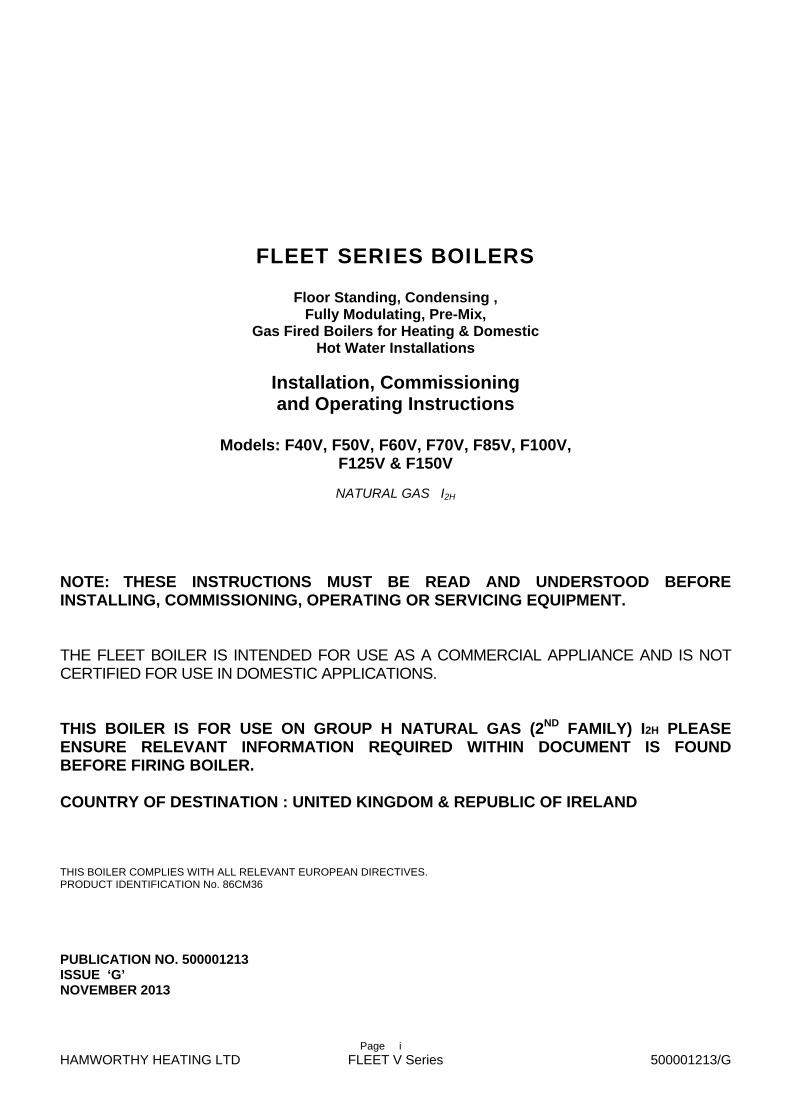
Figure 2.2 - Boiler Packaged Dimensions
Delivery Verification When taking delivery please ensure that you have received the correct number of boilers and flue collector manifolds to fulfil your order. If any item is missing please contact our after sales service team. Please provide details of your order such as order number and contract number as well as a detailed description of the missing item.
Frame Set and Pipe work Header Kits Where pipe work kits are supplied, these are packaged separately from the boilers. All ancillary items such as isolation valves and boiler make-up connectors are factory fitted and tested The whole is shrink wrapped for security and basic protection. Refer to Kit instructions 500005134 for specific information.
Model H mm W mm D mm Weight (kg)
F40V-80 1445 720 720 213
F50V-100 1445 720 720 213
F60V-120 1445 720 720 237
F70V-140 1445 720 720 237
F85V-170 1445 720 720 270
F100V-200 1445 720 720 270
F125V-250 1445 720 820 303
F150V-300 1445 720 820 329
F40V-120 2050 720 720 325
F50V-150 2050 720 720 325
F60V-180 2050 720 720 344
F70V-210 2050 720 720 344
F85V-255 2050 720 720 395
F100V-300 2050 720 720 395
F125V-375 2050 720 820 444
F150V-450 2050 720 820 470
Flue manifold 900 300 300 7

HAMWORTHY HEATING LTD
4 FLEET V series
500001213/G
3.0 SIZE AND SPACE REQUIREMENTS 3.1 The Fleet boiler range has been designed to utilise minimum floor space, therefore it is important that the plant room has sufficient ceiling height to allow for installation and connection to the flue system allowing for sufficient access at sides and behind boiler for pipe work connections. See Figure 3.1
Figure 3.1.1 - Dimensions and clearances
750 crs
950 min
clearance
700800 - F125/150V
650 - F40/100V
700A1
43
52
04
0
74
crs
65
06
06
crs
36
3
51
471
3
12
256
06
crs
61
4
18
30
80
28
0
15
0
28
0
230
25
172
B
Flue Connection C
Front view Plan view
Rear view Side view Fleet V Series - 3 high
Fleet V Series - 2 high
Flue removed for clarity
Flow
Air inlet
Electric
Safety ValveGas
Return
274
610
140
570638650
50
40
04
00

HAMWORTHY HEATING LTD
5 FLEET V series
500001213/G
Figure 3.2.1 – F40/F100V - water pipe work kit (2 high boiler installation shown)
504
350
100
11
0
GASR 1 ”1/2
FLOWDN80
RETURNDN80
600750750120
Figure 3.1.2 - Table Dimensions and clearances
BOILER MODEL Dimension F40V –F100V
A 580 580 680 680
B 320 320 320 350
C* 150 150 150 200
F125V—F150V
Two high Three high Two high Three high
C - a 150Ø flue manifold is provided to connect the modules C* - for models F125V-375 & F150-450, the flue termination is 200Ø
1/2” BSP Socket for pressure gauge
386
540
636

HAMWORTHY HEATING LTD
6 FLEET V series
500001213/G
Figure 3.2.2 – F125/150V - water pipe work kit (3 high boiler installation shown)
750
620
750
360
120
FLOWDN125
GASR2”
RETURNDN125
130
750120
396
656
786
1/2” BSP Socket for pressure gauge

HAMWORTHY HEATING LTD
7 FLEET V series
500001213/G
4.0 SITE LOCATION AND PREPARATION 4.1 Site Location. The boiler is heavy. Care must be taken when lifting the boiler For access purposes, the modules can be split and reassembled in the plant room The floor or plinth for the boilers and pipe work kit must be both flat and level to ensure
correct alignment of fittings and connections. The floor or plinth must be sufficiently strong to support the weight of both the boilers
and pipe work kit where used. The floor or plinth must be fireproof in accordance with BS 6644. The plant room must have sufficient space for installation of boilers, pipe work, pumps
controls, flues ventilation, access and servicing and other items of plant. 4.2 Gas Supply.
Gas supply pipes must be in accordance with BS 6891 or IGE/UP/2
Gas supply connections to the boiler must not be smaller than the connection on the boiler - refer to Figure 4.2 & Appendix 2 for the connection size.
Gas installation must be soundness tested to BS 6891 or IGE/UP/1 & IGE/UP/1A.
Gas installation must be purged to BS 6891 or IGE/UP/1 & IGE/UP/1A.
Inlet gas pressure to boiler measured at the gas valve, nominal 20mbar (minimum 17.5mbar) dynamic - refer to Appendix A
Boiler house gas isolation valve must be clearly identified and installed close to the entrance / exit.
Figure 4.2 - Gas Connection Point
Gas connection

HAMWORTHY HEATING LTD
8 FLEET V series
500001213/G
4.3 Flue System The Fleet flue systems supplied by Hamworthy are non UV stabilised polypropylene and
are therefore suitable for internal use only. For external flue runs and termination, either use the dedicated kits supplied by Hamworthy or refer to a chimney specialist .
Flue termination, routing and construction must comply with the requirements of the Clean Air Act 1956, BS 6644, BS 5440 and IGE/UP/10 where applicable.
Fleet boilers installed in modular format with a common flue, must use the manifold provided with the boiler prior to any connection to the flue system which must be suitable for condensing application.
Fleet V series boilers are suitable for open flue (type B23) installation, drawing combustion air from the plant room, - see section 5.2. For type B23 installations, the maximum number of modules firing into a common chimney is 9. For larger installations refer to HHL Technical. The flue system must be designed to limit the max. suction (cold) to 30Pa negative, measured at the connection to the boiler. If the suction is greater than 30Pa, refer to HHL technical. This condition must then be checked hot and with all boilers firing, the max. pressure at the connection to the boiler should be 150Pa positive. In the event that the flue system when hot does generate a suction, the max. suction is 100Pa.
For type B23 installations the Hamworthy supplied air inlet filter must be used at all
times. Refer to appendix C. Any stabiliser fitted must be in or close to the vertical chimney.
Due to the low flue gas temperature, (~50°C) condensation will occur in the flue, flue materials must be non-corrosive and utilise fully sealing joints.
Adequate facilities must be provided for draining the flue condensation from the flue system using the components available from HHL - refer to Appendix C. Horizontal runs of flue must provide condense drainage from the flue /chimney and must slope at 3° (50mm/m) along the horizontal length, towards the boiler. The flue system MUST NOT drain through the boiler - see section 5.2 .
For multiple boilers into a common flue header, the common header must slope at 3° back to the boilers and provision made to remove condensate from the header - see section 5.2 .
Horizontal flue runs must be kept as short as possible and be inclined at minimum 3° (50mm/m) towards the boiler.
For maximum equivalent flue lengths, refer to Appendix C.
Any flue must be self-supporting and separable from the boiler for servicing requirements.
Note: Due to high thermal efficiency of the Fleet boiler and the resultant low flue gas temperatures there will be visible pluming of the flue gases at the flue termination. This is likely even when the boiler is not operating at condensing temperatures.
Fan dilution - the design must provide for the use of balancing and trim dampers, and their location and operation must be such that the constraints detailed above can be met. Care must be taken to ensure that the fan performance is matched to deliver the appropriate dilution, whilst ensuring that excessive suction is not applied to the boilers. If in doubt, refer to HHL Technical.

HAMWORTHY HEATING LTD
9 FLEET V series
500001213/G
4.4 Water Supply
Feed and Expansion tanks to comply with static height requirements of HSE document PM5.
Cold feed and open vent pipes to comply with requirements of BS 6644. The Fleet boiler is fitted with an integral circulating pump, which will shut off
circulation through the heat exchanger 5 minutes after the boiler has ceased firing. The pump head available from the boiler, is only suitable for circulation in the primary circuit. This must be acknowledged in the system design. Pressurised system to comply with BS 7074. Each module is supplied with a safety valve set at 6barg to protect the boiler. It is imperative that a suitable safety valve is fitted to the installation in the event that the system design pressure is lower than the boiler maximum operating pressure, according to the requirements of BS6644 -2011 The Fleet boiler has an aluminium heat exchanger. It is a requirement that the
system & pipe work are flushed at least twice before adding water treatment and before installing the boiler.
The system water MUST be treated and maintained with an appropriate inhibitor (eg. Sentinel X100) and the PH MUST be managed between 7 & 8.5. Failure to observe this requirement will invalidate the warranty. In hard water areas (>180mg CaCO3/litre) precautions such as water treatment are
strongly recommended to prevent the build up of sludge and scale. Leaks in the system pipe work MUST be fixed to prevent dilution of water
treatment. Maximum working water pressure is 5.3bar. For minimum water pressure 0.5 bar - refer to Appendix E
Figure 4.4 - Water Connection Points
Return water connection
Flow water connection
Safety Valve
HAMWORTHY HEATING LTD
10 FLEET V series
500001213/G
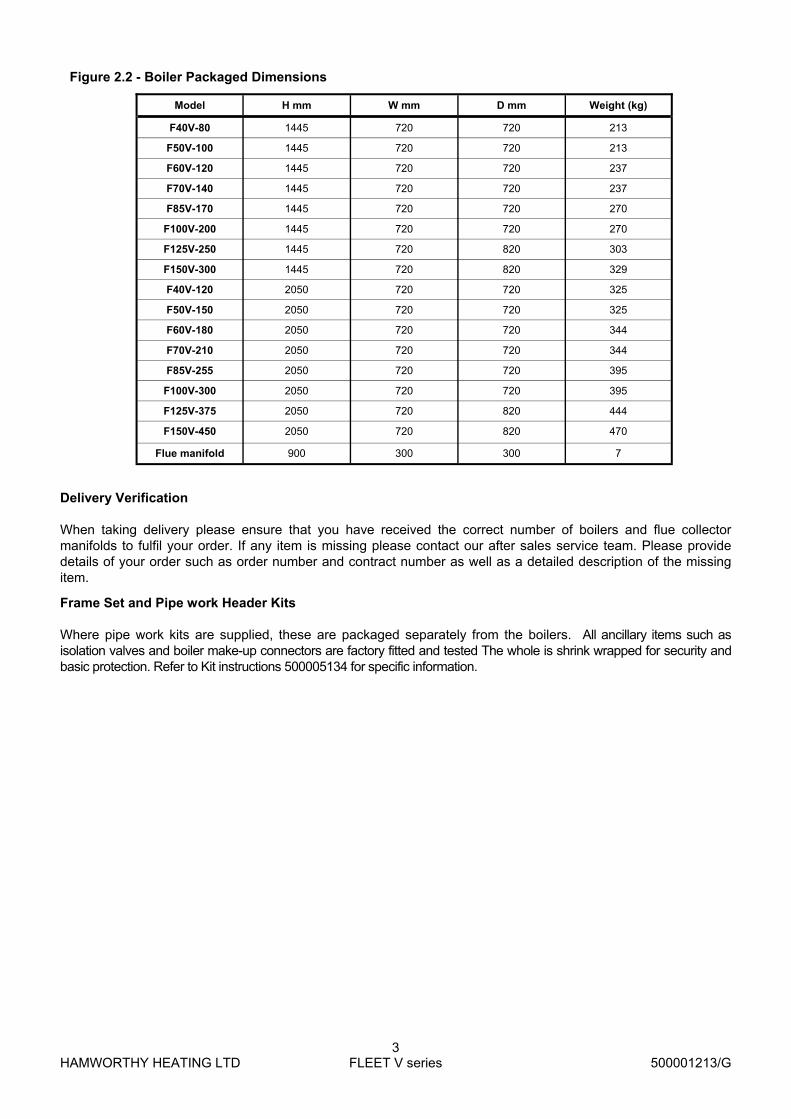
Heat exchanger warranty conditions, to be read in conjunction with Hamworthy Heating Limited’s terms and conditions of sale and service.
Heat exchanger warranties are conditional upon correct system design, installation, operation and maintenance in accordance with the manufacturer’s instructions, relevant legislation and best practice. In the event of defect or manufacturing fault it is the buyer's responsibility to prove so, clearly established and recognised by Hamworthy Heating Limited, the manufacturer's responsibility is as follows: The warranty is limited to the supply of the part recognised to be faulty for a period of 5 years from date of delivery and all transport expenses but excludes labour costs inherent to disassembly and reassembly, unless commissioned by Hamworthy Heating Limited or an approved Sub Contractor. THE APPLICATION OF THE WARRANTY IS SUBJECT TO: Compliance with the manufacturer’s recommendations as detailed in the operating and maintenance manual, ensuring that the commissioning is carried out by either Hamworthy Heating Limited or a competent engineer. To ensure that the settings and checks noted on the commissioning sheet (included in the maintenance manual) are recorded and detailed within the boiler log book. That the boiler maintenance is carried out by Hamworthy Heating Limited or a competent maintenance company, the maintenance regime detail shall be provided in writing, when required, to prove compliance with the operating and maintenance literature. Installation requirements shall be as defined and required by UK legislation, best practice and applicable European standards: Water Supply Feed and Expansion tanks to comply with static height requirements of BS6880 & BS6644. Cold feed and open vent pipes to comply with requirements of BS 6644. Pressurised system to comply with BS 7074. It is required that the system pipe work is flushed twice with a suitable flushing and cleaning agent and
before the new boiler(s) are installed (for example: Sentinel X300 for new systems, or Sentinel X400 for older systems) prior to the inclusion of water treatment
System water quality can be the cause of corrosion due to inappropriate Ph levels, oxygen presence and heterogeneity of different metal types within the system. To avoid this, the system water may have to be treated; the following limiting values must therefore be used for the composition of the heating water. (Please note: the guarantee may become null and void if the installation is not flushed and/or the water quality is inadequate).
Element Composition
Acidity Level (untreated water) 7.0 - 8.0 pH
Acidity Level (treated water) 7.0 - 8.5 pH
Conductivity (untreated water) 800 µS/cm (at 25°C)
Chlorides ≤ 150 mg/l
Iron ≤ 125 ppm (treated)
Copper ≤ 1 ppm (treated)
Aluminium ≤ 1 ppm (treated)
Water Hardness (CaCo3), ≤ 300 mg/l

HAMWORTHY HEATING LTD
11 FLEET V series
500001213/G
In line with the values above the following must also be taken into account: To ensure that the system is adequately protected against any possible corrosion of copper or copper-
bearing alloys that may be present within the system. (Note: Azole should be present in treatment chemicals to sequester the copper in solution and protect any yellow metal (i.e. copper and brass etc) components within the system.
The use of artificially softened water MUST be avoided due to its corrosive characteristics To ensure that any electrolytic action and subsequent corrosion is prevented. Electrolytic corrosion can
occur between dissimilar metals in the heating system, such as copper, brass, aluminium alloy and steel. To ensure that the use of a chemical corrosion inhibitor is used to protect the entire system. Leaks in the system pipe work MUST be fixed to prevent dilution of water treatment. It is a condition of this warranty that the appropriate water treatment is applied and that the products used have been found suitable for all materials used in the central heating system. Periodic inspections should be built into the service regime and where required replacement of inhibitors is undertaken. Although there are a wide range of water treatment products available, the following are compatible and should be considered: Sentinel Performance Solutions Ltd:
Sentinel X100 (protection agent) Sentinel X200 (lime scale remover) Sentinel X300 (cleaning agent for new installations) Sentinel X400 (cleaning agent for existing installations) Sentinel X500 (antifreeze plus protection agent)
Fernox:
Restorer (cleaning agent, for removing rust, lime and sludge) Protector (protection agent) F1 (protection agent)
The following applies to system design: In order to avoid thermal shock, water flow must not be able to be interrupted before the boiler stops firing. There must be provision to ensure that the heat exchanger is not susceptible to air locks. The air separator must be correctly sized and be equipped with an appropriate vent. A dirt separator must be correctly sized and fitted in the return close to the boiler(s) The system pressure must be in accordance with the information detailed within the operating and
maintenance manual (minimum 0.5 bar cold fill and 5.3 bar maximum working pressure). A filter must be mounted on the return pipe to the boiler(s). Minimum flow rates must be adhered to (as detailed within the operating and maintenance manual) In particular, but not limited to, the following conditions are not covered by the 5 year heat exchanger warranty: Defects resulting from incorrect installation, application, use, lack of the appropriate maintenance regime (in
accordance to the operating and maintenance manuals), deterioration or accident due to negligence or involvement by an unauthorised third party.
Damage due to acts of God, freezing, electrical storms, water damage, faulty flues, incorrect ventilation of the boiler room, and, in general, any action, negligence or clause recognised to be of an exceptional nature.
Presence of aggressive vapours (chlorine, solvents, etc...). Boiler gas configuration or type which is not appropriate to the type of gas approved for the appliance. Damage caused by use of spare parts not compatible with the product. Operation of the product at system pressures above that for which it was designed and manufactured.

HAMWORTHY HEATING LTD
12 FLEET V series
500001213/G
4.5 Condensate Connections Provision must be made for removal of condensate from the boiler and flue system. An inline condense drain must be fitted immediately before the connection of the
flue system to the boiler and taken to drain. The flue system must not be allowed to drain through the boiler flue manifold.
Condense is mildly acidic, typically pH3 - pH5. Condense pipe work must be non-corrosive and not copper. Hamworthy
recommend plastic waste pipe. Condense may be discharged to a standard drain subject to National or Local
regulations. Location of condense pipe work should prevent freezing within tundishes, traps and
pipe work. The connection to the boiler condense drain and flue condense drain, accepts a
straight push-fit coupling for 40mm o.d. plastic waste pipe. Maximum condensate production—15 l/h per 100kW firing capacity
Figure 4.5.1 - Boiler Condensate Connection - V series 2 high shown
Boiler Condensate connection 40mm o.d.
Flue manifold condensate connection 40mm o.d
Open Tundish
Minimum Fall 50mm/m(1 in 50)
Metal sheath to protectplastic pipe

HAMWORTHY HEATING LTD
13 FLEET V series
500001213/G
4.6 Electrical Supply WARNING! THIS APPLIANCE MUST BE EARTHED IN ACCORDANCE WITH IEE REGULATIONS
Boiler electrical supplies must not be switched by a time clock.
Boilers are suitable for 230Volt, 50Hz supply.
External fuses should be rated for 6 amps
Wiring must be completed in heat resistant cable size 1.0mm² csa.
Each boiler MUST have individual means of isolation.
Electrical isolators must facilitate complete electrical isolation.
Electrical isolators must have contact separation of minimum 3mm in all poles.
Electrical isolators must be installed in readily accessible locations.
Electrical supplies to boiler modules should only serve the boiler.
Where an external alarm is required, terminals are provided which are volt free and rated at 230v.
Time clock control should be via the boiler modules stop/start circuit (24V DC).
Any interlock circuit must be in series with the time control for each circuit. The interlock circuit must never be used to isolate the boiler electrical supply.
ADDITIONAL INFORMATION REGARDING ELECTRICAL SUPPLIES IS GIVEN IN BS EN60335, Part 1.
NOTE: The appliance must be isolated from the electrical supply if electric arc welding is carried out on connecting pipe work.
FOR TYPICAL SCHEMATIC DETAILS SEE FIGURE 4.6
FOR DETAILED WIRING INSTRUCTIONS SEE FIGURES 9.3.1 AND APPENDIX B
Figure 4.6 - Wiring Schematic
Earth
Mains S
upply
Secondary
Pum
p Output
230 v~50Hz
Pow
ered O
utput Supply
Live
Live
Live
Lock-Out
C
ontacts rated
Pow
ered Ou
tput
230V~50H
z, Max 1A
(Option 1)
Line Out
Line Out
Neutral
Neutral
Neutral
Neutral
Neutral
Norm
al Run
BM
S
Input Signal
Lock-Out
BM
S O
utput
Low
Voltage(O
ption 2)
Norm
al Run
Rem
ote On/O
ff Input S
ignal
Analogue
Input
Outside
Sensor
Safety Interlock
(Link If Not U
sed)
LPB
Bus
24VD
C
0~10V
Groun d
Ground
Ground
Ground
Ground
5VD
C
24VD
C
Slave
Signal
NO
T US
ED
NO
T U
SE
D
NO
T U
SE
D

HAMWORTHY HEATING LTD
14 FLEET V series
500001213/G
5.0 BOILER ASSEMBLY
5.1 General
Boilers are despatched to site as fully assembled units. The flue manifold and pipe work set (where applicable) are the only items that will need assembling on site.
Should access be an issue, the boiler modules can be dismantled to assist delivery into the plant room. To carry out this process, carefully remove the top panel, the front cover and side panels from each module. This will give access to 4 M10 nuts per module, securing the upper module to the lower module or base frame. Great care MUST be taken in separating and re-assembling the modules when in the required location, recognising the weight - refer to section 2. It is recommended that M10 lifting eyes are fitted to the boiler chassis in the four locations provided in the upright frame. During assembly it is important to take care to prevent damage to the boiler casing.
Boiler positioning must allow the minimum clearances detailed in Section 3.0 to facilitate access for flue and pipe work connections as well as maintenance. The boiler must be installed on a solid floor. In locating the boiler a pallet truck is recommended so as to avoid damage to the casing parts
Health and safety. Due to the weight of the boiler, care must be taken when manoeuvring the boiler. HHL suggest the use of a pallet truck
5.2 Water Connections
The connections provided on the boiler (refer to Appendix E and figure 4.4) are suitable for direct connection to the system pipe work. However HHL recommend the use of individual isolating valves, which should be fitted to each module to enable isolation from the system. However, the arrangement must comply with the requirements of BS 6644.
When installing water system pipe work, it must be self supporting and care must be taken to ensure that undue stress is avoided on the boiler flow and return connections. It is recommended that unions are fitted local to the boiler and outside of the casing, to permit future servicing requirements. Each module is fitted with safety valve rated at 6bar. The valve discharge pipe is routed to the rear of the boiler, where it must be piped to discharge via a tundish (not HHL supply) suitably located for ease of visibility. The Fleet is designed to operate at 20°C ∆T across the flow and return. Should the flow rate drop, the boiler controls will modulate the burner to maintain 20°C ∆T. The boiler module is fitted with a single speed circulating pump and flow is controlled through a balancing valve, which must be checked and set during commissioning. As a safety precaution, a flow switch is fitted to the boiler heat exchanger to shut the system down in the event of sudden adverse flow conditions. Where using Hamworthy Heating Ltd pipe work kits, assembly of these is detailed in Instruction Manual 500005134 supplied with kit.
5.3 Flue Connection 5.3.1 The Hamworthy Fleet V series boiler is designed for use with open flue systems type B23 - Intake from ventilated plant room and discharge via horizontal/vertical flue. For all B23 installations the Hamworthy supplied air inlet filter (Pt. No. 532812 008) MUST be used 1. With the boiler in its desired location, loosely engage the flue collector ducts into each other and position such that the spigots will fit into the respective flue sockets at the rear of the boiler. In assembling the flue ducts, it is advisable to lubricate the seal located in the socket fittings using the gel provided, to enable easy movement and adjustment. 2. Fit and secure the bottom closing plate to the base of the duct assembly. Do not fit the flue manifold at this stage as it may restrict access to the other connections. Note: Should modules be arranged in banks of 2 or 3 high, adjacent to each other, it is advisable to fit the water and flue connections to each individual bank prior to fitting the connections to the adjacent bank(s). Flue systems should be designed with reference to BS 5440 part 1, IGE/UP/10 and Third Edition of the 1956 Clean Air Act Memorandum.
To comply with the requirements of the Clean Air Act 1956 a maximum of 150 kW may be terminated with horizontal flue discharges.
Equivalent lengths for 90° bends and 45° bends are given in Appendix C.

HAMWORTHY HEATING LTD
15 FLEET V series
500001213/G
5.4 Electrical Connections:
The following electrical connections are provided on each module.
Supply: Live, Neutral and Earth. See Section 4.5 for details. Supply Input for Boiler Fault and Normal Run Signals Boiler General Fault Alarm Signal Output Boiler Normal Run Signal Output 0-10v Analogue Control Signal Input Remote on/off Control Input Boiler Shunt Pump Output Safety Interlock Circuit Input Optional LPB Bus for use with Merley boiler sequencer control 6.0 PRE-COMMISSIONING The following pre-commissioning check must be carried out before the boiler is commissioned.
6.1 Gas Supply.
Ensure that gas installation pipe work and meter has been soundness tested and purged to IGE/UP/1 or IGE/UP/1A as appropriate. Test and purge certificates should be available for viewing.
6.2 Ventilation
Ensure that ventilation and air supply to plant room is correct.
6.3 Pipe work, Valves and Pump
Ensure that;
System flushing and suitable water treatment has been implemented
Pipe work and valve arrangement is installed to Hamworthy Heating recommendations.
Circulating system is full of water, vented and pressurised appropriately.
Circulation pump is operational.
Pipe work connections to boiler are fitted correctly.
All necessary isolation valves are open.
Condense connections on boiler and flue are connected and piped to drain.
Heat load is available.
6.4 Flue
Ensure that;
Flue system is correctly designed and installed to suit boilers.
Flue passages to chimney are clear.
6.5 Electrical
Ensure that;
Electrical connections are correct and isolatable.
External controls are operational.
WARNING: WHEN THE FRONT COVER IS REMOVED AND THE BOILER IS OPERATIONAL, CARE MUST BE TAKEN WITH ELECTRICAL COMPONENTS AND
ACCESS TO PRIMARY INSULATION.

HAMWORTHY HEATING LTD
16 FLEET V series
500001213/G
TO CHECK A
1) Open C. 2) Open B to produce the mains gas supply pressure between A and B. 3) Close B. 4) System may be considered sound if over a period of 2 minutes any drop in pressure is less than 0.5 mbar (0.2" wg.).
Note:- Allow a manometer stabilisation period of approximately 1 minute before each 2 minute check period. Following soundness tests close valve B and remove manometer connections and tighten test points.
Water Systems The system MUST be flushed and a suitable water treatment implemented before commissioning the boiler. When installing water system pipe work, it must be self supporting and care must be taken to ensure that undue stress is avoided on the boiler flow and return connections. It is recommended that unions are fitted local to the boiler and outside of the casing, to permit future servicing requirements.
Each module is fitted with safety valve rated at 6bar. The valve discharge pipe is routed to the base of the boiler, where it must be piped to discharge via a tundish (not HHL supply) suitably located for ease of visibility.
The Fleet is designed to operate at 20°C ∆T across the flow and return. Should the flow rate drop, the boiler controls will modulate the burner to maintain 20°C ∆T. The boiler module is fitted with a single speed circulating pump and flow is controlled through a balancing valve, which must be checked and set during commissioning. As a safety precaution, a flow switch is fitted to the boiler heat exchanger to shut the system down in the event of sudden adverse flow conditions.
Where using Hamworthy Heating Ltd pipe work kits, assembly of these is detailed in Installation manual 500005134 supplied with kit.
7.0 CHECKS PRIOR TO LIGHTING
IMPORTANT: BEFORE PROCEEDING ENSURE THAT THE PRE-COMMISSIONING CHECKS ON PAGE 19 HAVE BEEN CARRIED OUT AND THE RESULTS SATISFACTORY.
7.1 Boiler Gas System Leak Check Ensure that the appliance manual gas service valve is in the OFF position. Although the boiler receives a gas leak check and gas train component integrity check prior to leaving the factory, transport and installation may have caused disturbance to unions, fittings and gas valve assemblies etc.
A procedure guide is given below. Care must be taken not to allow leak detection fluid (if used) on or near any electrical parts or connections.
NOTE: the test detailed below must be carried out on each module.
Figure 7.1 - Gas System Leak Check Diagram
Note:- Main Gas Supply Pressures are as follows; Natural Gas - 20mbar TO CHECK B
1) Turn off the electrical power and gas supply to the appliance. 2) Connect the manometer assembly to test point (Fitted on the inlet to the gas valve). 3) With A and B closed open C and moni-tor manometer over a 2 minute period, a rise indicates a leak on valve B.

HAMWORTHY HEATING LTD
17 FLEET V series
500001213/G
7.2 Checks prior to lighting the boiler Note: Refer to Appendix A, Gas Data Tables, for maximum inlet pressure for normal operation. 7.2.1 The Following checks must be made prior to lighting the boiler; 1. Open the front cover to gain access to the boiler components. The cover is secured with a 1/4 turn latch, requiring a flat blade screw driver to operate the latch. Carefully lift off the cover to expose the boiler components and installer wiring connections. Note: Before starting the boiler commissioning procedure verify the following; 2. Ensure that all external controls are not demanding that the boiler commences operation. 3. Ensure that the gas supply is connected, but the boiler module gas service valve(s) are closed, any unions or fittings are correctly tightened and test points are closed. 4. Check that the heating system has been flushed and refilled and that air has been purged from all high points. 5. Ensure that the system isolating valves are in the open position and that the water pressure within the heating system is correct. Minimum pressure 0.5barg. 6. Ensure that the flue ducts are correctly fitted and that they are free from obstruction. Check that the inlet and outlet terminal are located correctly and in accordance with regulations. 7. Ensure that the gas supply has been properly purged and verified for gas soundness. A purge and soundness certificate should be available from the gas pipe work installation contractor. 8. Turn on the mains gas supply. Check that sufficient gas pressure is available at the boiler, 17.5mbar Natural Gas. 10.Ensure that all electrical connections made to the boiler are correctly sized and installed. Refer to wiring diagram in Figure 9.3.1 11 Check that the boiler controls wiring has not been modified. Any modification could lead to boiler failure.
7.2.2 Gas inlet pressure test The gas pressure must be checked at the inlet to the boiler as shown in figure 7.2.2. This is to ensure that the gas pressure is both constant and sufficient to provide full burner output. To verify this the pressure has to be taken as a static and a dynamic reading. The dynamic reading cannot be taken until the boiler has been started - refer to 7.4
A maximum difference in gas pressure of 1 mbar must not be exceeded between static and dynamic conditions. 7.3 Commissioning the Boiler Once the preliminary checks have been completed and the gas inlet pressure has been verified as correct, commissioning of the boiler modules may begin. 7.3 Initial Lighting Only competent persons registered for working on non-domestic gas appliances should attempt the following operations. Before attempting to commission any boiler, ensure that personnel involved are aware of what action is about to be taken. Record all readings for future reference on relevant commissioning sheet. Allow system to warm up sufficiently to check operation of control thermostat. A combustion check must be taken when first commissioning the boiler. A sampling point is provided in the boiler - refer to section 8.6 - Combustion Checks 7.3.1 Operational Checks NOTE! Care should be exercised when the boiler is firing as the heat exchanger components can achieve temperatures, which could cause injury if touched. 1. Ensure that all external controls are in demand and that the gas supply to the module is isolated. 2. Switch the on/off switch located on the front panel of the boiler to the on position - see figure 8.1. 3. Start the individual boiler module using the mode button located on the fascia panel for the chosen module - detailed in section 8.2.5 - Controls Operation.. 4. The control thermostat is set using the button (2) on the fascia as detailed in section 8.2.5 - Controls Operation. 5. As the gas valve is closed, the low gas pressure switch will prevent the boiler from firing and the error code ‘E132’ will be displayed on the screen. Refer to section 8.2.4 of Controls Operation. 6. If the above procedure occurs correctly, open the gas isolating valve and the fault indication will extinguish. The boiler will commence its ignition sequence as previously described. This time, when the gas valve is energised the burner will ignite. 7. The flame ionisation signal generated whilst the boiler is firing (should be approximately 15-20µA, but not less than 3µA, can be viewed directly from the display screen. The value is set to read dc μA. Refer to section 8.2.1.2 - Controls Operation.
Fig 7.2.2 - Gas Inlet Pressure Test Point

HAMWORTHY HEATING LTD
18 FLEET V series
500001213/G
¼ turn latch On/Off switch
Fig 7.2.1 - On/Off switch - single module
At the end of the ignition proving period, 5 seconds, the spark ignition system will be switched off and the indicator on the control fascia extinguished.
After a period of 15 seconds the fan will alter speed and the burner modulation will be set according to the heat load.
If after the 5 second flame proving period the flame signal is below 3µA the boiler will shut down and attempt one restart.
NOTE: THE BOILER IS EQUIPPED WITH A RESTART FACILITY AND WILL ATTEMPT A SECOND IGNITION, DURING WHICH THE ABOVE PROCEDURES WILL BE REPEATED. AT THE END OF THE RESTART PROCEDURE, IF NO FLAME IS DETECTED AFTER THE FLAME PROVING PERIOD, THE BOILER WILL LOCKOUT. THE BOILER WILL NOT OPERATE UNTIL THE LOCKOUT HAS BEEN MANUALLY RESET.
7.4 Ignition Controller Check. 1. With the burner firing, the flame signal should be at least 3µA. Refer to Figure 8.2.9 - Maintenance functions. To check for correct operation of the ignition controller, close the gas valve. The boiler should shutdown after approximately one second and attempt a re-ignition. Check that the flame has been extinguished 2. Alternatively, the flame probe lead can be removed from the end of the flame probe, with the same result.
7.5 Gas Supply Pressure Check. 1. When the boiler modules have been checked for correct operation the gas supply pressure should be checked. This should be done with all modules firing. For Natural Gas, a nominal gas inlet pressure of 20mbar measured at the rear of the boiler is required, with
a maximum inlet pressure of 25mbar. 7.6 Combustion Checks “The boiler modules are factory pre-set, but, site checks must be done to confirm correct performance.”
1. Remove the flue gas sampling plug from the flue collector sump, accessible from the front of the boiler and insert the combustion analyser probe in the flue at the analysis point .
2. Ensure that an insertion distance of 50mm is set on the combustion analyser probe. NOTE: THIS DISTANCE MUST BE SET TO ENSURE ACCURATE ANALYSIS OF FLUE GASES. 3. Insert probe horizontally into the flue elbow until depth stop is met.
Figure 7.6 - Combustion Analyser Probe Setting
(Note: readings taken with front cover removed and 50mm probe insertion CO = < 80 ppm).

HAMWORTHY HEATING LTD
19 FLEET V series
500001213/G
High Fire Target Nat Gas - 9.0% ±0.25% CO2 If combustion level is outside of this range use the Cross Head Throttle Screw to adjust the mixture. THIS SETTING MUST BE CORRECT BEFORE CONTINUING To increase the CO2 level, turn the adjustment anti-clockwise. Figure 7.6.1- Adjusting gas valve throttle
Low Fire Target Nat Gas 9.0% ±0.25% CO2
If combustion readings are outside target range use Torx Bit to make adjustments To increase the CO2 level, turn the adjustment clockwise. Figure 7.6.3 - Adjusting gas valve offset
Models - F40V/ F50V F60V & F70V
Models - F85V/ F100V/ F125V & F150V
4. If combustion is outside of the ranges defined below the factory sealed valves may be adjusted using the following procedure .
High Fire Target Nat Gas 9.0% ±0.25% CO2
If combustion level is outside of this range use the Cross Head Throttle Screw to adjust the mixture. THIS SETTING MUST BE CORRECT BEFORE CONTINUING To increase the CO2 level, turn the adjustment anti-clockwise. Figure 7.6.2 - Adjusting gas valve throttle
Low Fire Target Nat Gas 9.0% ±0.25% CO2
If combustion readings are outside target range use Torx Bit to make adjustments To increase the CO2 level, turn the adjustment clockwise. Figure 7.6.4 - Adjusting gas valve offset
Models - F40V/ F50V F60V & F70V
Models - F85V/ F100V/ F125V & F150V
Fig 7.6.1 - Combustion settings

HAMWORTHY HEATING LTD
20 FLEET V series
500001213/G
Figure 8.2 - System configuration of boiler control (LMU) & system peripherals
LMU
QAC34 ..
Roo m Thermostat/ T ime Switch
RVA47
Bu ilding Automation / Remote Management
Service Tool
OCI420 AGU2.50 0
AGU2.51xxLPB
Clip-in Auxiliary modules
0..10 V 4..20 mA
OCI /ACS
8 CONTROLS OPERATION
5. Energise electrical supply and start the boiler module. The burner will ignite and run at 100% modulation.
6. Monitor the combustion readings on the combustion analyser at both Maximum and Minimum firing rates.- refer to section 8.2.8.2 - Controller Stop function
*Figure must not exceed 100ppm under normal operating conditions. If combustion readings fall within the required range the boiler module is set and operating correctly. If the combustion readings fall outside the required range the burner settings will require adjustment.
CONTACT HAMWORTHY HEATING TECHNICAL DEPARTMENT FOR FURTHER DETAILS
7. Shut down the boiler and isolate from the electrical supply. Remove instrumentation and replace test points and plugs.
8. Refer to section 8.1 - Controls Operation, to adjust the relevant boiler settings specific to the installation 7.7 Setting the flow rate to achieve 20°C ∆T
Before commissioning is complete, the flow rate must be checked and adjusted. A ball valve is located on the boiler return pipe, prior to the pump, and controls the flow through the boiler. Using the boiler flow and return temperature sensors visible on the display via the LMU programme. This MUST be carried out with the boiler running at maximum firing rate.
The 20°C ∆T condition across the boiler must be set as follows; 1 Run boiler at maximum rate. 2 Monitor flow temperature (displayed on main screen of HMI). 3 As boiler flow temperature rises, between 60°C & 80°C , press info button (to enter information mode) then hold down up/down arrows for 3 seconds (to enter extended information mode) use + button to scroll to b1 which displays boiler return temperature. 4 Within the case, locate the ball valve on the return pipe of the boiler, and then adjust to give 20°C differential between flow and return temperature. Opening the valve will decrease the differential/closing the valve will increase the differential. Press mode button to exit back to main screen and check flow temperature. It may be necessary to repeat the sequence several times to ensure an accurate 20°C delta T is set.
EB
A
RVS controller
HAMWORTHY HEATING LTD
21 FLEET V series
500001213/G
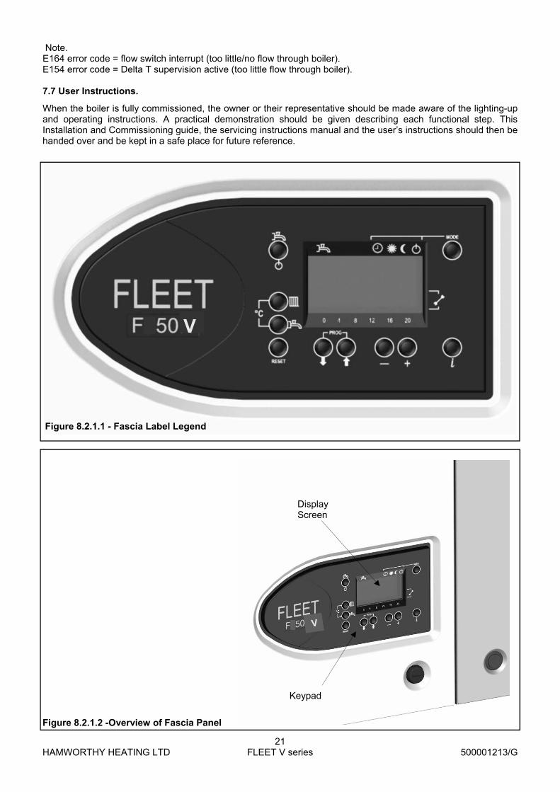
Figure 8.2.1.2 -Overview of Fascia Panel
Keypad
Display Screen
V
V
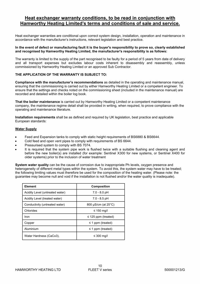
Figure 8.2.1.1 - Fascia Label Legend
Note. E164 error code = flow switch interrupt (too little/no flow through boiler). E154 error code = Delta T supervision active (too little flow through boiler). 7.7 User Instructions.
When the boiler is fully commissioned, the owner or their representative should be made aware of the lighting-up and operating instructions. A practical demonstration should be given describing each functional step. This Installation and Commissioning guide, the servicing instructions manual and the user’s instructions should then be handed over and be kept in a safe place for future reference.
HAMWORTHY HEATING LTD
22 FLEET V series
500001213/G
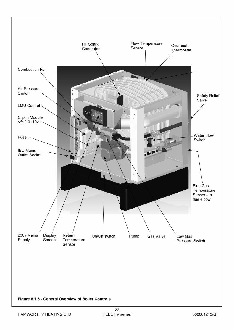
Figure 8.1.6 - General Overview of Boiler Controls
Low Gas Pressure Switch
Overheat Thermostat
HT Spark Generator
Combustion Fan
Air Pressure Switch
Fuse Water Flow Switch
230v Mains Supply
IEC Mains Outlet Socket
LMU Control
Clip in Module Vfc / 0~10v
Display Screen
On/Off switch
Flue Gas Temperature Sensor - in flue elbow
Safety Relief Valve
Pump Gas Valve
Flow Temperature Sensor
Return Temperature Sensor

HAMWORTHY HEATING LTD
23 FLEET V series
500001213/G
Button Operation Function
Lockout reset Resetting the LMU
Enable dhw mode dhw on/off - not used
Enable heating circuit selection of operating mode: mode Automatic operation
Continuous ‘Normal’ Operation
Continuous ‘Reduced’ Operation
Standby
Heating circuit Adjustment of boiler or room temperature setpoint temperature setpoint. dhw temperature setpoint Adjustment of dhw temperature setpoint - not used
Line selection (down / up) Selection of operating parameter
Adjustment of settings Adjustment of parameter settings
Information Select information display screens
Enable Maintenance mode Press buttons simultaneously to select
8.2.1 - Info button - refer to figure 8.2.1.1
A change on the information level can be made at any time by pressing the Info button. Additional pushes of the Info button will deliver the following data sequence provided by the information level.
dhw temperature - not used
Water Pressure
Operating phase - refer to section 8.2.15 Outside temperature Error code - refer to section 8.2.14 Boiler temperature Press one of these buttons to return to the default display
◄ ◄ ◄ ◄
X.
Ex
Extended Info mode - when on the information level, extended info mode levels b, c & d can be displayed.
Refer to Figure 8.2.2
Press both line selection buttons simultaneously for at least 3 seconds
Press one of these buttons to select the required display level
Press one of these buttons to select the required display value of the level
Press the Info button to switch to the info display
Press one of these buttons to return to the default display
|

HAMWORTHY HEATING LTD
24 FLEET V series
500001213/G
Figure 8.2.1.2 - Info display parameters
The parameters of groups b,C and d can only be displayed
Display level Name of LMU... variable
Description
General information (Enduser level)
Temperatures (Service level) ¹)
b 0 DiagnoseCode LMU...-internal software diagnostic code
b 1 TkRuec Boiler return temperature
b 2 TbwIst2 DHW temperature sensor 2 Not used
b 3 Tabgas Flue gas temperature Not used
b 4 TiAussen Outside temperature
b 5 TaGem Composite outside temperature
b 6 TaGed Attenuated outside temperature
b 7 TvIst Flow temperature AGU2.500...
b 8/ b9 Reserved
Process values (Service level) ²)
C 0 Reserved
C 1 IonStrom Ionization current
C 2 Gebl_Drehz Fan speed
C 3 Gebl_PWM_AusAkt Current fan control (PWM)
C 4 RelModLevel Relative output
C 5 Pumpe_PWM Pump setpoint (PWM) Not used
C 6 ek0 Control differential
C 7/ C8/ C9 Reserved
Setpoints (Service level) ³)
d 0 Reserved
d 1 Tsoll Setpoint of 2-position or modulating controller (PID)
d 2 TkSoll Current boiler temperature setpoint
d 3 TsRaum Room temperature setpoint
d 4 TbwSoll DHW temperature setpoint Not used
d 5 PhzMax Maximum degree of modulation in heating mode
d 6 NhzMax Maximum speed at maximum output in heating mode
d 7/ d8/ d9 Reserved
Note 1) 1 Press Info button 2 Press buttons for at least 3 seconds 3 Choose the relevant parameter with buttons
Note 2) 1 Press Info button 2 Press buttons for at least 3 seconds 3 Press button 4 Choose the relevant parameter with buttons
Note 3) 1 Press Info button 2 Press buttons for at least 3 seconds 3 Press button twice 4 Choose the relevant parameter with buttons
Note after about 8 minutes, the display will automatically change to the default display.

HAMWORTHY HEATING LTD
25 FLEET V series
500001213/G
Figure 8.2.1.3 - Operation and display philosophy

HAMWORTHY HEATING LTD
26 FLEET V series
500001213/G
Figure 8.2.2 - Screen Legend
Character Display Function
1 Water pressure sensor signal Display of water pressure (6 pointers) in increments of 10bar
2 Display (2) 4 x 7 large segments Display of current value
3 Maintenance indicator flashing Upper arrow - Chimney Sweep active Lower arrow - Controller Stop active
4 Display symbols Meaning of symbols: Display of dhw temperature or dhw heating active – not used Display of boiler or room temp. set- point, or space heating active. Display of outside temperature. Operational level ‘Normal’ Operational level ‘Reduced’ Display of flame Display of fault 5 Display (1) 4 x 7 small segments Display of time of day, parameter settings or error code.
6 Operating mode of heating circuit Operating mode is, or changes to:
Automatic Continuous ‘Normal’ operation Continuous ‘Reduced’ operation Standby
7 Operating mode of dhw. On or Off - not used
8 Time bar Display of time program of heating circuit

HAMWORTHY HEATING LTD
27 FLEET V series
500001213/G
105
7
6
2 3 4
5 8
1
7494
z31
/02
02
9
1 Operating mode of heating circuit
2 Operation of dhw circuit - not used
3 Operational level of heating circuit
4 Time of day
5 Actual value of boiler temperature
6 Water pressure
7 Flame status
8 Time pointer
9 Operating mode of boiler
Figure 8.2.3.1 - Default display
If no button is pressed for about 8 minutes, the screen will automatically return to the default display.
Figure 8.2.3.2 - Display of Status Code
When a status code is displayed, the display (1) shows
alternatively the time of day and the error code.
Press the Info button for the display of the error code
Press simultaneously both line selection buttons
for 3 seconds. The internal error code will be displayed.
Example “4975”
Press the info button to return to the info display.
Press to return to the default display.
(1)
(2)
8.2.3 - Default Display

HAMWORTHY HEATING LTD
28 FLEET V series
500001213/G
7494
z34
/090
274
94z2
6/1
202
In the case of a lockout code, the error code display flashes
together with an ‘Alarm symbol’;
The LMU will go to lockout
Example: “E150”
Press the Info button to switch to the error code Press both line selection buttons simultaneously
for 3 seconds. The internal error code will be displayed
Example “238” Press the Info button to switch to the Info display Press to return to the default display Note: After rectification of the fault, press the reset button (>0.6 seconds) to reset the LMU.
Figure 8.2.4 - Display of lockout code
304
7494
z35
/02
02
8.2.5 - Adjusting the heating circuit setpoint temperature
Press the flow temperature button to adjust the heating circuit setpoint Press to adjust the required setpoint Press to return to the default value Changes will be stored.
Figure 8.2.5 - Heating circuit setpoint temperature The room temperature setpoint or boiler temperature setpoint will be changed depending on the plant’s configuration ( with or without outside sensor). If no button is pressed for about 8 minutes, the screen will automatically return to the default display. Changes will be stored.
(1)
(2)
(1)
8.2.4 - Lockout Display
8.2.6 - Parameter settings for the Enduser
The boiler is supplied with default settings. These must be modified to suit individual Enduser needs.

HAMWORTHY HEATING LTD
29 FLEET V series
500001213/G
Press one of the line selection buttons. This will take you to programming level <<Enduser>>
Press the line selection button to choose the relevant line. The display shows <<Pxxx>>
Adjust the required value with one of these buttons. The adjustment is stored as soon as you change to some other line (to alter individual items, a change of parameter is required). The Enduser Parameter list details all possible settings.
Press button to leave the programming level. Changes will not be stored
Press the Info button to leave the programming level. Changes will be stored
Note: If no button is pressed for about 8 minutes, the screen will automatically return to the default display. Changes will not be stored. When switching to another level, changes will be stored.
Line Function Range Unit Resolution Default value
Time of day
1 Time of day 0...23:59 h / min 1 min ---
Setpoints
5 Reduced room temperature setpoint «TrSollRed» or (reduced boiler temperature setpoint «TvSollRed») (When using an additional room unit, line 5 will be hidden)
TRF...TRN °C 0.5 16.0
Time program HK1 (heating circuit 1)
11 Time program HC1 switch-on time 1st period 00:00...24:00 hh:mm 10 min 06:00
12 Time program HC1 switch-off time 1st period 00:00...24:00 hh:mm 10 min 22:00
13 Time program HC1 switch-on time 2nd period 00:00...24:00 hh:mm 10 min 24:00
14 Time program HC1 switch-off time 2nd period 00:00...24:00 hh:mm 10 min 24:00
15 Time program HC1 switch-on time 3rd period 00:00...24:00 hh:mm 10 min 24:00
16 Time program HC1 switch-off time 3rd period 00:00...24:00 hh:mm 10 min 24:00
Figure 8.2.6 - Overview of Enduser parameters
8.2.7 - Start-up / initialisation On startup after power-On, or after a lockout reset, the setpoints will be initialized. These setpoints apply until a first adjustment is made (e.g. via the screen display or PC parameterization): After a readjustment, these values will be overwritten with the new value and permanently stored in the LMU. When a new startup is made, or after power-On, the previous settings will be stored in the LMU. Also, the software version number of the operator module and that of the connected type of LMU... will be delivered. 8.2.8.1 - Chimney Sweep function
The chimney sweep function enables the boiler to be started up in heating mode by pressing both
buttons simultaneously for more than 3 seconds but for no more than 6 seconds.
On the display, the upper arrow of the maintenance function flashes and the currently selected
temperature appears. This function serves for making measurements on the boiler. When the chimney sweep
function is activated, the boiler will deliver maximum output until the limit thermostat cuts out.
To ensure maximum supply of heat, the chimney sweep function generates the forced signal for heat supply.
During the time that the Chimney Sweep is activated, an appropriate status code is delivered.
To close the function, press button

HAMWORTHY HEATING LTD
30 FLEET V series
500001213/G
8.2.8.2 - Controller Stop function
The controller stop function enables the boiler’s heat output to be adjusted manually in heating mode by
pressing both buttons simultaneously for more than 6 seconds. On the display, both arrows of the maintenance function flash and the currently selected temperature
appears and the display shows the adjusted relative boiler output.
The function serves for making measurements on the boiler and allows the boiler output to be increased /
decreased by pressing buttons .
Minimum and maximum output can be directly selected by pressing the line selection buttons
Note: - If the controller stop function is triggered via PC tool ACS420, the current setpoint of burner output will
appear on the display, but the settings are locked.
To close the function, press button 8.2.8.3 - Time of day function To ensure that this function operates, the time of day and time settings must be correctly set. Refer to section,
Parameter settings for Enduser, to setup the program.
Note:- each time button is pressed during the time setting, the seconds are set to 0 and the clock
continues to run while making the setting.
8.2.9 - Heating circuit operating modes The control provides 4 different heating circuit operating modes for LMU... heating circuit 1. They can be
directly selected depending on the requirements - see figure 8.2.9
The operating modes are selected by pressing button .
On the LCD, a pointer below the respective symbol points to the selected heating circuit operating mode.
8.2.10 - Error code display
In the event of a nonvolatile LMU... lockout position, fault is continually displayed. In addition, the diagnostic
code on the display flashes (refer to figure 8.2.4 and table 8.2.10).
To cancel the lockout position, press lockout reset button for at least 2 seconds. 8.2.11 - Display of operating phases (display level A4)
The operating phases according to the LMU…’s sequence diagram can be displayed (display level A4 press Info button 3 times). Assignment of the display code and the LMU...’s phase designation is as shown in figure 8.3.11
Operating mode Designation Effect of selection
Automatic operation Heating circuit 1 (HC1) according to time switch program 1
Standby Heating circuit 1 switched off Frost protection functions active
Continuous ‘Normal’ operation
Heating circuit 1 continuously on according to the adjusted nominal room temperature setpoint or heating circuit setpoint
Continuous ‘Reduced’ operation
Reduced room temperature set point or heating circuit frost protection setpoint
Figure 8.2.9

HAMWORTHY HEATING LTD
31 FLEET V series
500001213/G
8.3 - Functions 8.3.1 Frost Protection Note: - to access this function, the circulating pump must be wired to the LMU through a suitable contactor. There are two levels of frost protection available dependent on the sensor options used. 1st stage - When the boiler water temperature is below 5°C, the burner and the heating pump are switched on. When the temperature increases and exceeds 15°C, the burner stops and the pump continues for the duration of the pump overrun. 2nd stage - This additional function uses the outside air temperature (if a sensor has not been fitted, the function is blocked) and provides three levels of activation.
If the outside temperature is less than or equal to –5°C, the pump operates continuously
If the outside temperature is between –4 & 1.5°C, the pump operates for 10 minutes every 6 hours.
If the outside temperature is greater than 1.5°C, the pump is switched off.
Note:- any demand for dhw is given priority. Should protection be required for the building fabric, then a QAA73 programmable room sensor must be used to maintain the internal building temperature. 8.3.2 Anti Legionella To prevent the development of pathogenic bacteria in the domestic hot water tank during prolonged shut downs or low storage temperatures, the dhw must be heated once a week to a temperature greater than 60°C. The anti legionella function heats the dhw once a week on Monday, after the first load, to 65°C.
8.3.3 Pump overrun When the heating mode ends, the heating circuit pump remains on for a period (depending on the settings used - QAA73: 544). In dhw systems, when the dhw heating period ends, the heating pump remains on until the return temperature drops below 70°C. During this period, the dhw selector valve (if fitted) is in the open position. 8.3.4 Pump or selector valve kick If either the heating circuit pump or dhw selector valve have not been activated for more than 24hours, then during an off period the pump or valve is activated for 5 seconds.
8.3.5 Boiler overheat protection The boiler flow sensor in combination with the return sensor, provide overheat protection as follows:
If the first level temperature is exceeded, a fault code is displayed.
If the second level temperature is exceeded, an alarm code is displayed and the boiler will switch off. The boiler must be reset to restart.
To restart the boiler, the temperature must fall, accordingly the fan and pump will continue to operate until the boiler heat exchanger temperature drops. Additionally, should the ∆T across the boiler heat exchanger exceed 25°C, the burner will reduce output to minimum rate. Should the ∆T exceed 30°C, the burner will shutdown. 8.3.6 Anti-cycling Dependent on the installation and the minimum firing rate of the boiler, the control monitors the heating temperature curve and will hold off a boiler from firing and thus reduce the number of operations.
8.3.7 Automatic summer / winter switching Note: - This function is only available when an outside sensor is fitted. The automatic summer/ winter switching function enables the summer mode to be switched to winter mode (vice versa) throughout the year, without the need for manual intervention. The heating is shut down when the average outside temperature measured over the preceding 24hours is greater than 1°C above the set point (20°C). The heating is automatically started up again when the average outside temperature measured over the preceding 24hours is less than 1°C below the lower limit of the hysteresis threshold of the set point (18°C). Note: - The switch over setting is set to 19°C and can only be changed using the QAA73 room sensor. The automatic mode must obviously be activated on the boiler as well as on the QAA73, for the function to operate. The function is automatically activated by a default setting in the QAA73. 8.3.8 - Start-up / initialisation On startup after power-On, or after a lockout reset, the setpoints will be initialized. These setpoints apply until a first adjustment is made (e.g. via the display or PC parameterization): After a readjustment, these values will be overwritten with the new value and permanently stored in the LMU.
When a new startup is made, or after power-On, the previous settings will be stored in the LMU. Also, the software version number of the operator module and that of the connected type of LMU... will be delivered to the display.

HAMWORTHY HEATING LTD
32 FLEET V series
500001213/G
Error code
Internal Error-Code
Potential cause Actions
0 No entry in code 10 Fault outside sensor 20 142 Short Circuit Boiler Flow Sensor Check temp sensor in water flow pipe & replace if nec-
essary 143 Open Circuit Boiler Flow Sensor Check connections to temp sensor in water flow pipe
Check temp sensor in water flow connection & replace if necessary
28 Fault flue gas sensor 32 Fault flow temperature sensor 2 40 144 Short Circuit Boiler Rtn Sensor Check temp sensor in water rtn pipe & replace if neces-
sary Open Circuit Boiler Rtn Sensor Check connections to temp sensor in water rtn pipe
Check temp sensor in water rtn connection & replace if necessary
50 Fault DHW temperature sensor 1
52 Fault DHW temperature sensor 2 61 Fault room unit 1 Check room device 62 Wrong room unit 1 or wrong radio clock con-
nected Connect compatible room control unit
77 Fault air pressure sensor 78 Fault water pressure sensor 81 518 LPB Short Circuit or no power supply Check connections to clip in (switch off and isolate
boiler before working on mains wiring) 82 Address collision on LPB... Check addresses of connected modules 91 Data overflow in EEPROM 92 Hardware fault in electronics 95 Invalid time of day Set correct time
100 2 clock time masters
105 Maintenance message P629 to reset : change from 0 to 1 110/111 Limit thermostat has cut out Allow the boiler to cool and reset thermostat
Investigate cause of overheating (see section 9.3) 113 Flue gas supervision equipment has cut out 117 Water pressure too high 118 Water pressure too low 119 Water pressure switch has cut out Check water pressure 128 Loss of flame during operation Check connections to flame probe
Investigate flame probe condition Check combustion when boiler is firing
130 Flue gas limit temperature exceeded 132 Safety shutdown Check gas pressure
Check flue & condensate trap for blockages Check safety switches
133 No flame on completion of safety time Check operation of gas valve. Check spark igniter 134 Loss of flame during operation 140 Inadmissible LPB segment number/device N° 148 Incompatibility LPB... interface / basic unit
151 552 Relay clip in faulty Check connections to clip in Check and replace clip in module (switch off and isolate boiler before working on mains wiring)
152 Fault in connection with LMU settings 153 LMU has locked out Press reset button
(code appears if reset button is pressed when there are no faults)
154 Flow Problems Check water flow through the boiler & Check the pumps 160 Fan speed threshold not reached Check obstructions in fan, burner & flue.
Check non-return valve operates Check heat exchanger for debris
161 Maximum fan speed exceeded Check parameters 162 Fault air pressure switch (does not close) 164 Fault heating circuit flow switch / pressure
switch
166 Fault air pressure switch (does not open) 180 Chimney sweep function active 181 Controller stop function active 183 LMU... in parameter setting mode
Figure 8.2.10 LMU Error Codes

HAMWORTHY HEATING LTD
33 FLEET V series
500001213/G
8.3.9 - BMS 0~10v DC control of LMU Before programming changes are made, ensure the boiler is set to standby mode. The following parameters need to be changed on the boiler LMU when a BMS 0-10 V signal is being used to control the boiler modules directly. All parameters can be changed using the keypad on the boiler display panel or via the computer link using the Siemens software. Press and hold both up and down arrow keys for at least five seconds to enter advanced parameter list H90 displayed top right of HMI screen. Use either up or down arrow key to scroll through the parameter list and stop at H618 - Default value is 0 Two options for control are available : Option 1 (preferred option for multiple boilers on a modulating 0-10V signal controlling the load) To enable 0-10v control over the boiler power range, change the setting by using the + or – key and set value to 5. Press mode button to store change and return to home screen. Option 2 (if the 0-10V signal is only being used to enable the boilers and is not modulating) To enable 0-10v control over the boiler temperature set point, change the setting by using the + or – key and set value to 4. Press mode button to store change and return to home screen Press and hold both up and down arrow keys for at least five seconds to enter advanced parameter list H90 displayed top right of HMI screen. Use either up or down arrow key to scroll through the parameter list and stop at H622 - Default value is 80 Change this value to match the required flow temperature set point at maximum (10v) e.g. 80 = 80°C max set point. Press mode button to store change and return to home screen 0-10v signal wiring can now be connected to connections 15 and 16 of the terminal rail to control the boiler.
Boiler PC Req’d setting Function 618 526 4 0–10 V - temperature 618 526 5 0–10 V - load (preferred option for modulating load) 622 528 As req’d (80°C) Max temp = 10 V 623 529 As req’d (20%) Min % load = 20 %
It may be necessary, depending on the operating temperature required, to raise the maximum operating temperature possible from the individual boiler modules. As standard the boiler modules leave the factory with a maximum operating temperature of 85°C. Where a higher operating temperature is required the following parameter change must be made. 505 181 As req’d (90°C) Max operating temp.
8.3.10 - Access to LMU Fault Log The LMU control retains historical fault information of the last 6 faults, as read only via the Engineer level access. The current fault relates to the actual lockout at the time of the visit. Once reset, the current fault becomes the 1st fault and the remaining history is shifted back to the 5th fault, losing the previous 5th fault history. The Albatros code is the ‘E’ display code supported by the internal code Note : When connecting to a QAA73 unit refer to Hamworthy OEM manual 500001140 When connecting to a Merley control unit refer to Hamworthy OEM manual 500001210
No QAA73...
Function Level QAA73...
700 1st past value of lockout code counter Engineer * 701 1st past value of lockout phase Engineer * 702 1st past value of internal diagnostic code Engineer * 728 1st past value of ALBATROS error code Engineer * 703 2nd past value of lockout code counter Engineer * 704 2nd past value of lockout phase Engineer * 705 2nd past value of internal diagnostic code Engineer * 729 2nd past value of ALBATROS error code Engineer * 706 3rd past value of lockout code counter Engineer * 707 3rd past value of lockout phase Engineer * 708 3rd past value of internal diagnostic code Engineer * 730 3rd past value of ALBATROS error code Engineer * 709 4th past value of lockout code counter Engineer *
710 4th past value of lockout phase Engineer * 711 4th past value of internal diagnostic code Engineer * 731 4th past value of ALBATROS error code Engineer * 712 5th past value of lockout code counter Engineer * 713 5th past value of lockout phase Engineer * 714 5th past value of internal diagnostic code Engineer * 732 5th past value of ALBATROS error code Engineer * 715 Current value of lockout code counter Engineer * 716 Current value of lockout phase Engineer * 717 Current value internal diagnostic code Engineer * 733 Current value of ALBATROS error code Engineer *
Figure 8.3.10—LMU Fault Log

HAMWORTHY HEATING LTD
34 FLEET V series
500001213/G
Figure 8.3.11 - Operating phases

HAMWORTHY HEATING LTD
35 FLEET V series
500001213/G
Display Meaning Internal operating phases of the LMU...
00 Standby (no demand for heat) PH_STANDBY
01 Prevention of startup PH_STARTVER
02 Fan runup PH_THL1_1 PH_THL1_2
03 Prepurging PH_TV
04 Waiting time PH_TBRE PH_TW1 PH_TW2
05 Preignition time PH_TVZ
06 Safety time, constant PH_TSA1_1 PH_TSA2_1
07 Safety time, variable PH_TSA1_2 PH_TSA2_2
10 Heating operation PH_TI PH_MODULATION Heating mode
11 DHW operation PH_TI PH_MODULATION DHW mode
12 Parallel operation of space heating and DHW heating
PH_TI PH_MODULATION Heating and DHW mode
20 Postpurging with the last control of operation
PH_THL2_1 PH_TN_1
21 Postpurging with control of prepurging PH_THL2_2 PH_TN_2
22 Home run PH_TNB PH_TLO PH_TNN
99 Lockout position (display of the current error code)
PH_STOER
Note: -If operating phases are passed very quickly or skipped, the relevant display code will not appear.
Figure 8.3.12 - Operating phases

HAMWORTHY HEATING LTD
36 FLEET V series
500001213/G
9.0 FAULT FINDING The Fleet boiler is equipped with full self-diagnostic fault indication, with faults allocated a code, which is displayed (flashes) on the display - refer to section 8.3.9 - Maintenance functions. The common fault codes are detailed in section 8.3.9 - Maintenance functions.. Fault codes not detailed in this manual should only be investigated by an Engineer.
Should a fault code appear which cannot be reset, or a fault code repeatedly occurs, contact Hamworthy Heating for assistance. Do not continue to operate or use the boiler
as this may cause damage to the controls.
9.1 Safety Temperature Limiter (Limit Thermostat) 1. The electronic control thermostat has several safety levels built in such that a controlled shutdown should occur before the safety temperature limiter is activated. Should these safety levels be overridden (say external pump overrun failure after shutdown) the safety temperature limiter will trip initiating a boiler shutdown, preventing the boiler from firing. The code (110) on the controls display will flash indicating that the safety temperature limiter has tripped. 2. The safety temperature limiter is auto reset located on the top rear of the heat exchanger block. Once the boiler has cooled to normal operating temperature, pushing the reset pushbutton on the display (refer to section 8.1.1 - Controls Operation) will reset the lockout. Should the lockout code not extinguish and the boiler does not fire up, it is possible that the safety temperature limiter will not reset because the boiler is still too hot. 3. Always carry out an investigation to ascertain the reason for overheating. The most common cause of overheating is lack of water flow rate through the boiler possibly caused by a faulty pump or blockage in the heat exchanger circuit due to system debris.
Figure 9.2 - Water Flow Switch
9.2 Water Flow Switch 1. The water flow switch is located in the return pipe before the pump (see figure 9.2) and will prevent the boiler from firing should there be inadequate or no water flow. This is to protect the heat exchanger from damage in the absence of water (dry firing) which will cause cata-strophic failure of the heat exchanger. 2. The operation of the flow switch can be checked by closing one of the isolating valves connecting the boiler to the system., this will generate error E164 on the LMU display.
9.3 Ignition Controller 1. The flame is under constant supervision by the burner ignition controller. The controller monitors the flame’s ability to rectify an AC current. If the flame diminishes for whatever reason and the rectified current drops below the controller’s minimum detection current (3µA DC), the controller will de-energise the gas control valve within 1 second and commence a restart. Failure to establish and detect a flame during the light-up sequence will result in burner shutdown and lockout within 5 seconds, requiring a manual reset to restart the ignition sequence. Refer to section 8.3.9—Maintenance functions..
2. If the boiler continues to lockout, then an investigation must be made to ascertain the cause. Refer to figure 8.3.10 - Operating faults, for possible causes of lockout.
3. A false flame signal at the start and during pre-purge will cause the boiler module to restart its ignition se-quence at the end of the pre-purge period. If this occurs 3 times in succession the controls will disable operation of the boiler module, requiring reset of the module. Refer to section 8.3.10 - Operating faults
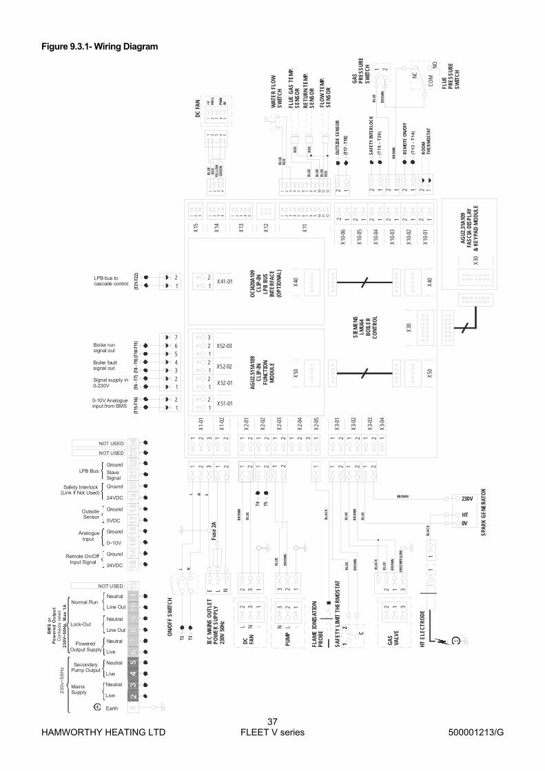
HAMWORTHY HEATING LTD
37 FLEET V series
500001213/G
Figure 9.3.1- Wiring Diagram
11 1 1 1 1 1 11
1 11
1 111
1+V H
ALL
PWM
0V
2 22
2 222
2
3 33
3 333
3
44 5
4 444
4 5
5 55
66
77
88
99
1010
1111
1212
2
22 2 2 2 2 2 2
2
1
33
12
22
234567
2
1
11
1
1
123
2 1 2 1 2 1 22222
11111
2 1
1 2 1 2 1 2 1 2 1 2 3 1 1 2 1 2 1 2 1
X1-0
1X1
5
X14
X13
X11
X12
X30
X40
X50
X50
X40
X10-
06
X10-
05
X10-
04
X10-
03
X10-
02
X10-
01
X2-0
1
X1-0
2
X52-01
X51-01
X41-01
X52-02
X52-03
X2-0
2
X2-0
3
X2-0
4
X2-0
5
X3-0
1
X3-0
2
X3-0
3
X3-0
4
SIEM
ENS
LMU6
4BO
ILER
CONT
ROL
AGU2
.511
A109
CLIP
-INFU
NCTI
ON
MO
DULE
OCI
420A
109
CLIP
-INLP
B BU
SIN
TERF
ACE
(OPT
IONA
L)R
ED
GR
EEN
YELL
OW
RED
BLU
E
RED
RED
RED
BLU
E
BROWN
BLA
CK
BLU
E
BR
OW
N
BR
OW
N
GRE
EN/Y
ELLO
W
BLU
E
BLU
E
BLU
E
BLU
E
BLU
E
FLO
W T
EMP.
SE
NSO
R
RETU
RN T
EMP.
SE
NSO
R
FLUE
GAS
TEM
P.
SENS
OR
WAT
ER F
LOW
SW
ITCH
DC F
AN
21
X30
AGU2
.31A
109
FASC
IA D
ISPL
AY&
KEYP
AD M
ODU
LE
FLAM
E IO
NISA
TIO
NPR
OBE
2
1
1 3
230V
0VHT
1
2 1 3
C
12
HT E
LECT
RODE
GAS
VA
LVE
SPAR
K G
ENER
ATO
R
SAFE
TY L
IMIT
THE
RMO
STAT
2 3
L NN L
3 21 1
DC FAN
PUM
P
2 33 21 1
BLU
E
BR
OW
N
BLA
CK
BR
OW
N
BLU
E
ON/
OFF
SW
ITCH
1 2
BR
OW
N
BLU
E
L NEFu
se 2
A
L NL N E
IEC
MAI
NS O
UTLE
T PO
WER
SUP
PLY
230V
50H
z
BLA
CK
1 2
BLU
E
BR
OW
N
GAS
PR
ESSU
RESW
ITCH
BR
OW
N
NO
NC
CO
M
FLUE
PR
ESSU
RESW
ITCH
12
REM
OTE
ON
/OFF
(T1
3 -
T1
4)
SAFE
TY IN
TER
LOC
K
(T1
9 -
T2
0)
RO
OM
THER
MO
STAT
OU
TSID
E SE
NSO
R
(T17
- T1
8)
(T21
-T22
)(T
6 - T
7)(T
8 - T
9)(T
10-T
11)
(T15
-T16
)
T2 T3
T4 T5
LPB bus to cascade control
0-10V Analogue input from BMS
Signal supply in 0-230V
Boiler fault signal out
Boiler run signal out
Earth
Mains Supply
Secondary Pump Output
23
0v~
50
Hz
Powered Output Supply
Live
Live
Live
BM
S o
r P
ow
ere
d O
utp
ut
23
0V
~5
0H
z, M
ax
1A
Co
nta
cts
rate
d
Line Out
Line Out
Neutral
Neutral
Neutral
Neutral
Neutral
Lock-Out
Normal Run
Remote On/Off Input Signal
Analogue Input
Outside Sensor
Safety Interlock(Link If Not Used)
LPB Bus
24VDC
0~10V
Ground
Ground
Ground
Ground
Ground
5VDC
24VDC
SlaveSignal
NOT USED
NOT USED
NOT USED

HAMWORTHY HEATING LTD
38 FLEET V series
500001213/G
10 SERVICING A competent person registered for working on non domestic gas appliances should check and ensure that the flue, its support and terminal, the ventilation to the boiler house, safety valve, drain, water filter if fitted, pressure gauge, etc.; are in a serviceable and working condition and still comply with the relevant standards and codes of practice - see Section 4. 10.1 Regular servicing is recommended, preferably by a Hamworthy appointed person, and at least annually, to ensure trouble free operation. For Fleet boilers, Hamworthy would recommend an additional 6 monthly examination following commissioning, acknowledging site conditions and running hours. Although cleaning of flueways may not be necessary on a yearly basis, it is important that all controls and safety features are checked for correct operation. Note:- Measuring flue gas CO2 and gas temperatures will give an indication of the state of the boiler flueways and waterways. Results should be compared with previously measured values to establish possible loss of efficiency.
10.2 Annual Service Before servicing the boiler, the following procedure must be carried out :-
WARNING: Isolate all electrical supplies and turn off the gas service valve. 1) Open the front casing by turning the 1/4 turn latches with a flat bladed screw driver. Note the latch mechanism passes through slots in the chassis top and bottom. Once removed access is gained to the controls panel, the heat exchanger components and the combustion system assembly.
2) Disconnect the H.T and flame probe connectors from the respective probes.
3) Disconnect the fan power supply and control leads from the fan taking care with the latch on each connector.
4) Check that the gas service valve is closed, then undo the compression union on the inlet to the gas valve.
5) Carefully disengage the flexible air inlet duct from the venturi and remove the electrical plug from the gas valve.
6) Remove the 3 M6 socket head screws securing the fan /burner duct assembly to the heat exchanger and carefully remove the assembly and the sealing gasket. Carefully remove the burner from the heat exchanger,.
7) Remove and inspect H.T. electrode and flame probe, ensure they are free from debris or deposits. – See Figures 10.2. 10.2.1 & 10.2.2
8) Check the burner and clean using a soft brush if required (if possible use a vacuum cleaner to remove
the dust from inside the burner tube). After cleaning the inside, the burner tube can be washed using a soapy water solution. Tap the burner flange firmly downwards on a block of wood to dislodge any residual debris from inside the burner tube. A damaged or cracked burner should be replaced. Note:- Do not use a wire brush to clean the burner. 9) Carefully remove the insulation pad from the heat exchanger back plate (accessed through the burner cavity) and replace with a new pad ensuring the edges are ‘tucked in’ to the gap past the last section
9) Separate the gas valve / venturi from the fan inlet noting it’s orientation and inspect the fan scroll and impellor, clean and check for damage.
10) Clean and check the venturi for contamination.
11) Remove the fan from the burner duct and inspect the non return valve in the duct for smooth operation.
12) Separate the inlet flange /elbow fitting from the gas control valve by removing the 4 M5 socket cap head screws. Check that the mesh inlet filter in the gas valve is clear of debris, remove any foreign objects caught in the filter. Re-assemble in reverse order taking care to inspect and if necessary, replace any o-rings, gaskets or seals. Refer to Section 8, Commissioning and Testing, and test all gas joints broken or disturbed for soundness before firing. Carry out a combustion check by testing the flue gas CO2 and CO levels as detailed in Section 8.2.
10.3 Four Year Service Repeat the annual service as previously described but do not refit any components to the heat exchanger. Isolate the boiler flow and return connections from the heating system.
10.3.1 To clean the heat exchanger, the use of a high pressure water hose (40-80 psi) is recommended for the primary flue gas path. However provision must be made for the drainage of water used in this process. At the rear of the boiler remove the condensate drain trap assembly from the flue elbow. Connect a hose (32mm id.) to the flue elbow and take to a suitable drain or receptacle. The cleaning water and any debris will exit the sump through this opening.
To clean the condensing flue gas path, isolate the boiler from the heating system and drain the boiler heat exchanger using the drain valve provided in the return pipe. Disconnect the electrical supply to the pump, return sensor and the flow switch. Carefully support the pump, disconnect the unions and remove the pump. Remove the 2 M6 screws securing the return elbow /pipe assembly to the heat exchanger and carefully remove the assembly. Remove the 4 screws (M8) securing the heat exchanger assembly to the chassis backplate. Disconnect the heat exchanger flow connection from the heating system and the flue pipe from the sump elbow and carefully slide the heat exchanger assembly
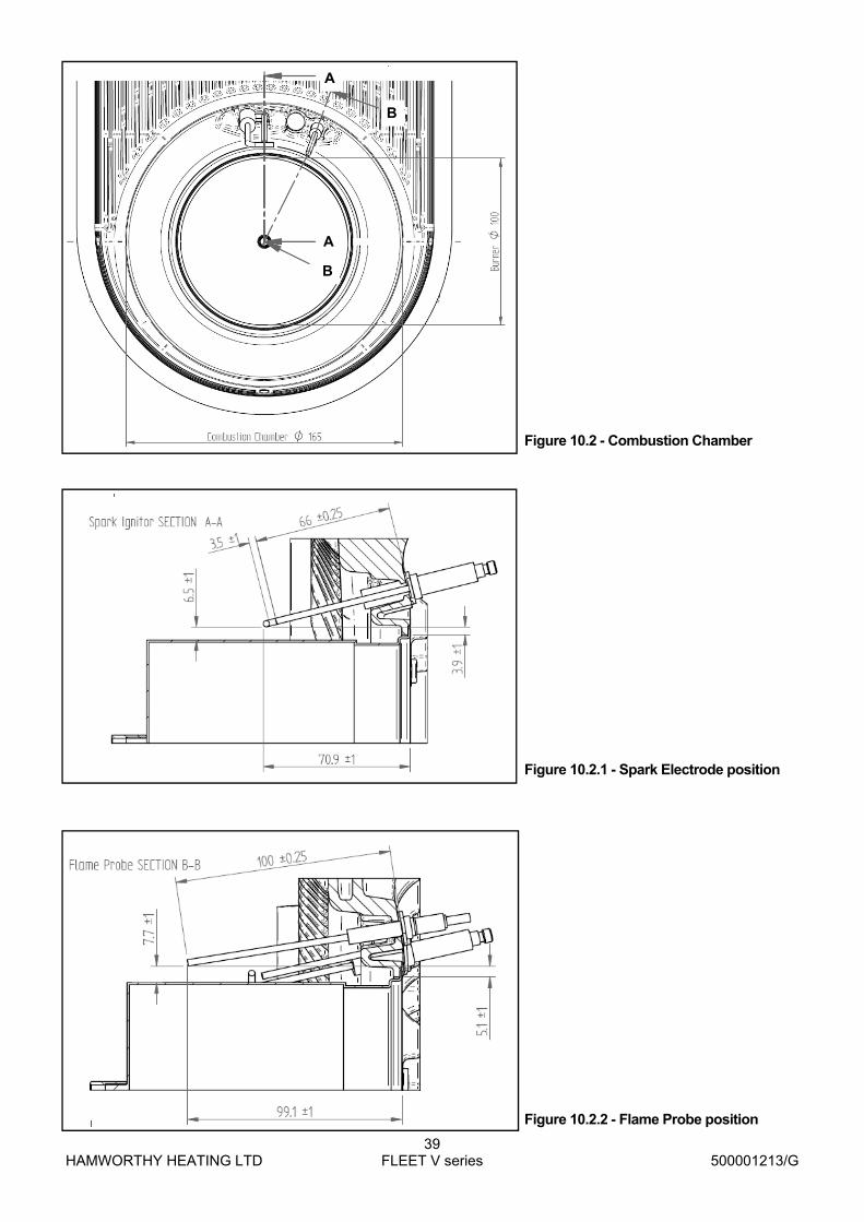
HAMWORTHY HEATING LTD
39 FLEET V series
500001213/G
Figure 10.2 - Combustion Chamber
A
A
B
B
Figure 10.2.1 - Spark Electrode position
Figure 10.2.2 - Flame Probe position

HAMWORTHY HEATING LTD
40 FLEET V series
500001213/G
forward. With the heat exchanger removed from the appliance, remove the plastic sump from the heat exchanger sealing plate and withdraw the sump away from the sealing plate. The heat exchanger fin matrix is now accessible and the flue ways can be cleaned using a 25mm wide * 1mm thick* 400mm strip to clean between the fins, ensuring that any debris is collected .
When clean, re-assemble in reverse order using new seals /gaskets where appropriate.
Re-fit the pump and return pipe assembly. Open the isolating valve and test all joints broken or disturbed for water soundness.
Re-fit the burner assembly. Test all gas joints broken or disturbed for soundness before firing.
Refer to Section 8 Commissioning The Boiler.
11.0 REPLACEMENT OF FAILED COMPONENTS There are a number of components listed below which can be replaced simply and quickly by following the given procedure. In each case the operation of each replaced component must be checked by carrying out the appropriate part of the commissioning procedure. See Section 8: COMMISSIONING & TESTING. Note:- Isolate all electrical supplies to the boiler module before opening the front cover and commencing any servicing or component exchange procedure. Turn off the gas at the service valve.
11.1 HT Electrode and Flame Probe - Part nos. 533805029 & 533805021 Note:- The electrode and flame probe ceramics are very fragile. Disconnect the HT cable from the electrode. Remove the 2 M4 screws securing the electrode to the heat exchanger and carefully remove the electrode and it’s gasket. Check the condition of the ceramic, wires and the spark gap. Adjust if necessary. In replacing the electrode, fit a new gasket and take care when feeding the wires through the heat exchanger aperture. Carefully re-connect the HT cable to the electrode. Disconnect the cable from the flame probe. Remove the 1 M4 screw securing the probe to the heat exchanger and withdraw the probe. Check the condition of the ceramic and wire. In replacing the probe fit a new gasket and refit the cable. To check the position of the electrode and probe in relation to the burner, remove the burner and refer to Figures 10.2. , 10.2.1 & 10.2.2
11.2 Flow / Return sensor - part no. 533901549 Note: The flow/return sensors are immersed in the water circuit. To remove/replace will require the heat exchanger to be drained. The two identical sensors are located in the return elbow and flow elbow. Prior to removal, check the resistance of the sensor against Figure B 1.3 In refitting the sensor, a sealant will be required on the threads. Check for water soundness before firing the boiler.
11.3 Flue Gas sensor - Part no. 533901549
The flue gas sensor is located in the flue elbow. Prior to removal, check the resistance of the sensor against Figure B 1.3 In refitting the sensor, a sealant will be required on the threads. Check for soundness of the joint when firing the boiler.
11.4 Temperature Limiter (Limit Stat) Part no. 533901583 The limit stat is a bi-metallic disc type located on the top of the last heat exchanger section, secured by a spring clip. The thermostat can be accessed through the rear panel. Remove the thermostat from the clip and disconnect the electrical connections. Beware the terminals are 230v! When refitting the control ensure that it is fully engaged in the clip.
11.5 Water Flow switch - Part no. 533901548 Note: The flow is immersed in the water circuit. To remove/replace will require the heat exchanger to be drained. The water flow switch is located in the return pipe on the pump inlet. Undo the union and carefully withdraw the switch assembly from the pipe. The switch consists of a magnetic reed switch providing open or closed circuit. In fitting a replacement switch ensure that a new sealing gasket is used.
11.6 Gas Valve Part no. 533903040 - F40 - F70V Part no. 533903044 - F85 - F150V All models - isolate the gas supply using the valve located in the bottom left hand corner. Disconnect the electrical lead and pressure sensing tube. Models F40 V/F50V /F60V & F70V Remove the 4 - M4 screws securing the inlet elbow to the gas valve. Support the weight of the valve and remove the 3 - M4 screws securing the valve to the venturi. Replace the gas valve using new seal / ‘o’ ring. Models F85V/F100V/F125V & F150V Remove the 4 - M5 screws securing the inlet fitting to the gas valve. Support the weight of the valve and remove the 4 - M5 screws securing the gas valve and spacer assembly to the venture. Remove the 4 - M5 screws securing the spacer to the gas valve. Replace the gas valve using new ‘o’ rings. All models - reassemble in reverse order and check all joints for gas soundness.
11.7 Fan Part no. 533901376 - F40 - F70V Part no. 533704009 - F85 - F125V Part no. 533704010 - F150V To remove the fan it is preferable to remove the complete fan, gas valve and venturi assembly. To improve access, remove the casing top panel. Disconnect the electrical lead and pressure sensing tube from the gas valve. Disconnect the two electrical plugs (power supply and speed control signal) from the fan motor. Disconnect the gas supply from the inlet to the gas valve. Loosen the worm drive securing the air inlet duct to the venturi.

HAMWORTHY HEATING LTD
41 FLEET V series
500001213/G
12.0 RECOMMENDED SPARES
Please Note:- To ensure the correct spare parts are despatched by our spares department, it is imperative that the complete Boiler/Module/Control Panel Serial Numbers are given. The Boiler and Module Serial Numbers are located on the Data Plates affixed to the combustion chamber front panel. The Electrical Panel Serial Number is located inside the Control panel on the rating label. These numbers MUST be quoted when ordering spare parts.
SPARES ITEM PART No.
ELECTRICAL ITEMS LMU control - F40V Nat Gas ........................................................................................................................................ 533901623 LMU control - F50V Nat Gas ........................................................................................................................................ 533901624 LMU control - F60V Nat Gas ........................................................................................................................................ 533901625 LMU control - F70V Nat Gas ........................................................................................................................................ 533901626 LMU control - F85V NatGas ......................................................................................................................................... 533901627 LMU control - F100V Nat Gas ...................................................................................................................................... 533901628 LMU control - F125V Nat Gas ...................................................................................................................................... 533901629 LMU control - F150V NatGas ....................................................................................................................................... 533901630 Display PCB ................................................................................................................................................................... 533901437 HT Ignition Transformer ............................................................................................................................................... 533901542 Flow / Return Sensor ...................................................................................................................................................... 533901549 Flue Gas Sensor . ........................................................................................................................................................... 533901549 Water Flow Switch . ........................................................................................................................................................ 533901548 Temperature Limiter ....................................................................................................................................................... 533901583 HT Ignitor Electrode ........................................................................................................................................................ 533805029 Ht Ignitor Lead .............................................................................................................................................................533901547 Flame Sensing Probe ..................................................................................................................................................... 533805021 On/Off switch . ................................................................................................................................................................ 533925009 Fascia fuse T2A . ............................................................................................................................................................ 533922009 Clip in Module - vfc + 0~10v - AGU2.511A109 ............................................................................................................ 533901438 Clip in Module - LPB Bus communication - OCI420A109 ........................................................................................... 533901456
Remove the 4 - M5 screws securing the fan assembly to the burner transition duct. Take care not to drop any screws into the duct opening. Carefully withdraw the complete assembly from the air inlet and place on a suitable working area. Remove the screws securing the gas valve and venturi assembly to the fan inlet, noting the position of the venturi. All models - reassemble in reverse order using new gaskets and check all joints for gas soundness.
11.8 Main control pcb - LMU - refer to spares list The LMU is located on the electrical control panel which is secured to the boiler chassis by 2 spring latches. Pull the panel forward to disengage the latches. If a ‘clip in module’ is fitted, this must be removed and transferred to the new LMU. Carefully disconnect the plug connecting the clip in to terminal X40 or X50. Depress the latch at the plug end of the clip in and disengage the module from the LMU. Unplug all electrical connections from the LMU noting respective positions. Remove the 4 - M5 screws securing the LMU to the panel and withdraw. Fit the replacement control in reverse order. Remember to apply the parameters local to the installation - refer to section 8.
11.9 Display screen - Part no. 533901437
Carefully disconnect the ribbon cable connecting the screen to the LMU terminal X30. Remove the 4 screws securing the screen to the fascia moulding, taking care not to loose the button covers, which are loose when the assembly is separated. Refit the button covers to the new display and secure to the fascia moulding.
11.10 Low gas pressure switch - Part no. 533901497
Isolate the gas supply using the valve located in the bottom left hand corner. Disconnect the electrical plug after removing the securing screw. Remove the screw securing the switch to the gas inlet fitting on the gas supply pipe. When re-fitting a replacement switch remember to set the operating pressure to 12mbar.
11.11 Air Pressure Switch - Part no. 532496004
Disconnect the sensing tube from the switch noting the position. Disconnect the electrical connections noting their position. Remove the 2 screws securing the switch to the control panel. The replacement switch is factory set.

HAMWORTHY HEATING LTD
42 FLEET V series
500001213/G
CASING ITEMS Front door panel ..........................................................................................................................................................560650267 LH side panel - F40 / F100V ......................................................................................................................................530650469 RH side panel - F40 / F100V ....................................................................................................................................530650470 LH side panel - F125 / F150V ...................................................................................................................................530650471 RH side panel - F125 / F150V ..................................................................................................................................530650472 Top Panel - F40 / F100V ...........................................................................................................................................530650477 Top Panel - F125/F150V ...........................................................................................................................................530650478 For service or spares please contact :-
Hamworthy Heating Ltd Phone Number ..............................01202 662500 Fleets Corner Fax Number .....................................01202 665111 Poole Service .............................................01202 662555 Dorset BH17 0HH Spares ..............................................01202 662525 Technical .........................................01202 662500
MECHANICAL ITEMS Burner Fabrication - F40V /F50V .............................................................................................................................533301030 Burner Fabrication - F60V /F70V ..............................................................................................................................533301031 Burner Fabrication - F85V /F100V ..............................................................................................................................533301032 Burner Fabrication - F125V ........................................................................................................................................533301033 Burner Fabrication - F150V ........................................................................................................................................533301034 Gas Control Valve - F40V/F70V ..............................................................................................................................533903040 Gas Control Valve ‘O’ ring - F40V/F70V .................................................................................................................531299051 Gas Control Valve - F85V/F150V ................................................................................................................................ 533903044 Gas Control Valve ‘O’ ring - F85V/F150V .................................................................................................................... 742111245 Combustion Fan - F40H/F70H ...................................................................................................................................533901376 Combustion Fan - F85H/F100H/F125H .....................................................................................................................533704009 Combustion Fan - F150H............... .............................................................................................................................533704010 Venturi - F40V/F50V ...................................................................................................................................................532418008 Venturi - F60V/F70V ...................................................................................................................................................532418005 Venturi seal - F40V/F70V .........................................................................................................................................531201067 Venturi - F85V/F150V ..........................................................................................................................................532418007 Venturi seal - F85V/F150V .........................................................................................................................................742121238 Low Gas Pressure Switch ..........................................................................................................................................533901497 Air Pressure Switch ....................................................................................................................................................532496004 Flue System Non Return Valve ...................................................................................................................................530650455 Safety Pressure Relief Valve ......................................................................................................................................531905013 Gasket - Burner to heat exchanger ...................................................................................................................531201162 Gasket - Fan to burner duct .......................................................................................................................................531201168 Gasket - Burner duct ..................................................................................................................................................531299041 Gasket - Ignitor ..........................................................................................................................................................531201160 Gasket - Probe ..........................................................................................................................................................531201161 Pump F40V/F70V.........................................................................................................................................................530905059 Pump F85V/F125V.. . ..................................................................................................................................................530905060 Pump F150V. ...............................................................................................................................................................530905061 Gasket - Pump ............................................................................................................................................................531201150 View Port Sight Glass ..................................................................................................................................................339907043 Air Inlet Filter............... ..................................................................................................................................................532812008 Heat exchanger insulation pad.....................................................................................................................................533806119

HAMWORTHY HEATING LTD
43 FLEET V series
500001213/G
APPENDIX A - GAS DATA
F85V F100V F125V F150V
Gas Inlet Connection Pipe Thread Size R ¾” R ¾” R 1” R 1”
Nominal Inlet Pressure Nat Gas -mbar 20
Maximum Inlet Pressure Nat Gas -mbar 25
Gas Pressure Switch Setting Nat Gas -mbar
Gas Flow Rate (max. per module) Nat Gas -m3/h 8.25 9.7 11.7 14.6
Target CO2 % at High / Low fire Nat Gas ±0.25% 9.0
12.5
GENERAL DATA BOILER MODEL F40V-80 F40V-120 F50V-100 F50-V150
Boiler Input (maximum) - kW (Gross) 82.0 123.0 102.6 153.9
Boiler Input (maximum) - kW (Nett) 73.8 110.7 92.4 138.6
Boiler Output kW (maximum) condensing 50/30°C - kW 80 120 100 150
Boiler Output kW (maximum) non condensing 80/60°C - kW 72.2 108.3 90.2 135.3
Boiler Module Output (minimum) 80/60°C - kW 7.2 7.2 9.0 9.0
F60V-120 F60V-180 F70V-140 F70V-210
Boiler Input (maximum) - kW (Gross) 123.0 184.5 143.6 215.4
Boiler Input (maximum) - kW (Nett) 110.8 166.2 129.4 194.1
Boiler Output kW (maximum) condensing 50/30°C - kW 120 180 140 210
Boiler Output kW (maximum) non condensing 80/60°C - kW 108.2 162.3 126.4 189.6 Boiler Output (minimum) 80/60°C - kW 10.8 10.8 12.6 12.6
GAS DATA - per boiler module F40V F50V F60V F70V
Gas Inlet Connection Pipe Thread Size R ¾” R ¾” R ¾” R ¾”
Nominal Inlet Pressure Nat Gas -mbar 20
Maximum Inlet Pressure Nat Gas -mbar 25
Gas Pressure Switch Setting Nat Gas -mbar 12.5
Gas Flow Rate (max. per module) Nat Gas -m3/h 3.9 4.8 5.8 6.8
Target CO2 % at High / Low fire Nat Gas ±0.25% 9.0
Figure A1– Gas data
F85V-170 F85V-255 F100V-200 F100V-300
Boiler Input (maximum) - kW (Gross) 174.4 261.6 205.2 307.8
Boiler Input (maximum) - kW (Nett) 157.0 235.5 184.8 277.2
Boiler Output kW (maximum) condensing 50/30°C - kW 170 255 200 300
Boiler Output kW (maximum) non condensing 80/60°C - kW 153.4 230.1 180.6 270.9 Boiler Output (minimum) 80/60°C - kW 15.3 15.3 17.9 17.9 F125V-250 F125V-375 F150V-300 F150V-450
Boiler Input (maximum) - kW (Gross) 256.4 384.6 307.6 461.4
Boiler Input (maximum) - kW (Nett) 231.0 346.5 277.2 415.8
Boiler Output kW (maximum) condensing 50/30°C - kW 250 375 300 450
Boiler Output kW (maximum) non condensing 80/60°C - kW 225.6 338.4 270.8 406.2 Boiler Output (minimum) 80/60°C - kW 21.6 21.6 26.9 26.9

HAMWORTHY HEATING LTD
44 FLEET V series
500001213/G
APPENDIX B - ELECTRICAL CONNECTIONS AND CONTROLS
B1.1 Electrical Supply IMPORTANT: Individual boilers must be earthed. The boiler must be isolated from the mains electricity supply in the event of electric arc welding being carried out on any connecting pipe work. 1. Wiring external to the boiler must be installed in accordance with the IEE Regulations and any local regulations which apply. Wiring must be completed in heat resistant 3-core cable of 1.0mm² cross sectional area. Boilers are normally supplied for connection to a 230 volts, 50Hz mains supply. The boiler control is supplied with a replaceable fuse (T4A). External fuses should be 6A for all boilers.
2. 3-Phase Electrical Supplies. Individual modules of Fleet boilers and any boilers installed in close proximity to each other MUST NOT be supplied from different phases of a 3 phase supply. The method of connection to the mains electricity supply must facilitate complete electrical isolation of the single boiler / battery with a separation of at least 3mm in all poles. 3. A mains isolator must be provided adjacent to the boiler in a readily accessible position. The supply should only serve the boiler. 4. Multiple modules. It is highly recommended that each boiler is connected via its own mains isolator to facilitate servicing and maintenance of the individual boiler whilst leaving the remaining boilers in operation. 5. Further details regarding connection to the electricity supply are given in BS EN 60335, Part 1 or BS 3456, Part 201.
WARNING: THE MAINS POWER SUPPLY MUST NOT BE SWITCHED BY A TIME-CLOCK CONTROL.
CAUTION: DO NOT FEED MAINS VOLTAGE ONTO THE TIMER TERMINALS
6. The mains power supply must be maintained at all times. Each Fleet boiler module incorporates a remote enable link, which can be used to operate the boiler(s) under a timed regime. The boiler controls provide a 24V DC signal that can be fed through a volt free contact for operation. Refer to BS 6644 for further information on installing the electrical supply. 7. The integral pump in Fleet boilers is managed by the LMU boiler control.
NOTE: FOR BASIC TERMINATION DIAGRAM SEE FIGURE 4.6
ELECTRICAL DATA - per boiler module BOILER MODEL F40V F50V F60V F70V
Nominal supply voltage 230V ~ 50Hz
Power Consumption (maximum) - W 160 160 160 160
Start and Run Current (per module) - A 0.85/0.35 0.85/0.35 0.85/0.35 0.85/0.35
F85V F100V F125V F150V
Nominal supply voltage 230V ~ 50Hz
Power Consumption (maximum) - W 350 450 350 600
Start and Run Current (per module) - A 2.1/1 2.1/1 2.1/1 2.4/1.2
Figure B1.1 - Electrical supply

HAMWORTHY HEATING LTD
45 FLEET V series
500001213/G
BMS Connections For 0 - 10v connection, the input signal must be connected to terminals 15 & 16 - see figure 4.6 Note: any safety interlocks MUST be wired across the 0– 10v circuit using suitable low voltage contact ratings. For connection of an external alarm device, use terminals 8 & 9, which are volt free and rated at 230v - see figure 4.6 For an optional programmable room thermostat, use connector X10-01 on the LMU - see figure B.1.3
Figure B1.2 - External Control Wiring for Multiple Module Installation
LNE
3
3
3
2
2
1
1
2
1
13 14
13 14
13 14
21 22
21 22
21 22
15 16
15 16
15 16
External Control
OptionalExternalControl
Boiler 1Terminal Rail
Boiler 2Terminal Rail
Boiler 3Terminal Rail
0~10V
0~10V
0~10V
ControlSignal0~10V orEnable
Note:- each module requires independent isolation of electrical supply and control signals. Signal cables must not be run in the same conduit as mains voltage cables
Option 1 - reference should be made to Building Regulations and CIBSE Guide ‘Energy Eff iciency in Buildings’ for controls requirements. All modules must be sequenced. Enable - will give On/Off control of the modules 0~10V - will give modulation control of each module Option 2 provides modulation control of up to 16 modules.
Local Isolator
Option 1 Remote ControlOption 2 Merley Cascade Control
LPBBus
Control Signal0-10V or enable

HAMWORTHY HEATING LTD
46 FLEET V series
500001213/G
T [°C] R[Ohm] T [°C] R[Ohm] T [°C] R[Ohm]
-30.0 175203 50.0 3605 130.0 298
-25.0 129289 55.0 2989 135.0 262
-20.0 96360 60.0 2490 140.0 232
-15.0 72502 65.0 2084 145.0 206
-10.0 55047 70.0 1753 150.0 183
-5.0 42158 75.0 1481 155.0 163
0.0 32555 80.0 1256 160.0 145
5.0 25339 85.0 1070 165.0 130
10.0 19873 90.0 915 170.0 117
15.0 15699 95.0 786 175.0 105
20.0 12488 100.0 677 180.0 95
25.0 10000 105.0 586 185.0 85
30.0 8059 110.0 508 190.0 77
35.0 6535 115.0 443 195.0 70
40.0 5330 120.0 387 200.0 64
45.0 4372 125.0 339
Figure B1.3 - Sensor resistance values

HAMWORTHY HEATING LTD
47 FLEET V series
500001213/G
APPENDIX C - FLUE DATA - Natural Gas
C1.0 FLUE SYSTEM 1. Detailed recommendations for flue systems are given in BS 6644, and IGE/UP/10. All flue discharges for plant exceeding 150kW output must comply with the third edition of the 1956 Clean Air Act Memorandum.
WARNING: THE FLUE DISCHARGE FROM A FLEET BOILER WILL GENERATE A PLUME AT THE TERMINAL EXIT. THIS MUST BE CONSIDERED WITH REGARD TO TERMINAL
LOCATION AND ADJACENT BUILDING FABRIC.
FOR B23 INSTALLATIONS THE AIR INLET FILTER (Pt. No. 532812008) MUST BE USED. C1.1 General Requirements The Fleet V series boilers are designed to be used with natural draught or pressurised flues. Flue systems should be designed in accordance with regulations and with reference to BS 6644 and IGE/UP/10. The following points should be noted: a. Due to the high thermal efficiency of the boiler, condensation will occur in the flue. It is strongly recommended that the design of the flue system recognises this. HHL supply plastic flue components and suitable terminals to discharge the flue gases safely. The Fleet flue systems supplied by Hamworthy are non UV stabilised polypropylene and are therefore suitable for internal use only. For external flue runs and termination, either use the dedicated kits supplied by Hamworthy or refer to a chimney specialist . b. Care should be taken to ensure that the flue is installed such that any condensation is continuously drained. Any flue system with a horizontal section should have a maximum slope of 3° upwards in the direction of the exhaust gas flow. All joints should be such that any condensation is directed back down the slope to an open drain connection in the flue. The drain pipe must be manufactured from a corrosion resistant material and be at least 15mm diameter. It must also have a fall of at least 3° (approx. 50mm per meter) and connect to a drain via a waste trap. c. Boiler flue outlet sizes - A flue system designed with the same diameter as the boiler flue outlet may not provide
* Note:- Flue gas volumes are corrected to a flue gas temperature of 15°C and barometric pressure of 1013.25mbar.
FLUE DATA BOILER MODEL F40- 80V F40-120V F50-100V F50-150V
Flue connections - mm 150 150 150 150
Pressure at the boiler flue outlet - Pa/mbar 150/1.5 150/1.5 150/1.5 150/1.5
Approx. Flue Gas Volume @ 9% CO2 - m3/h* 104 156 130 195
Approx. Flue Gas Temperature 80/60° (50/30°C) gross 60/ (40)
F60– 120V F60-180V F70-140V F70-210V
Flue connections - mm 150 150 150 150
Pressure at the boiler flue outlet - Pa/mbar 150/1.5 150/1.5 150/1.5 150/1.5
Approx. Flue Gas Volume @ 9% CO2 - m3/h* 156 234 182 273
Approx. Flue Gas Temperature 80/60° (50/30°C) gross 60/ (40)
F85– 170V F85-255V F100-200V F100-300V
Flue connections - mm 150
Pressure at the boiler flue outlet - Pa/mbar 150/1.5 150/1.5 150/1.5 150/1.5
Approx. Flue Gas Volume @ 9% CO2 - m3/h* 220 330 260 390
Approx. Flue Gas Temperature 80/60° (50/30°C) gross 60/ (40)
150 150 150
F125– 250V F125-375V F150-300V F150-450V
Flue connections - mm 150
Pressure at the boiler flue outlet - Pa/mbar 150/1.5 150/1.5 150/1.5 150/1.5
Approx. Flue Gas Volume @ 9% CO2 - m3/h* 326 489 390 585
Approx. Flue Gas Temperature 80/60° (50/30°C) gross 60/ (40)
200 150 200
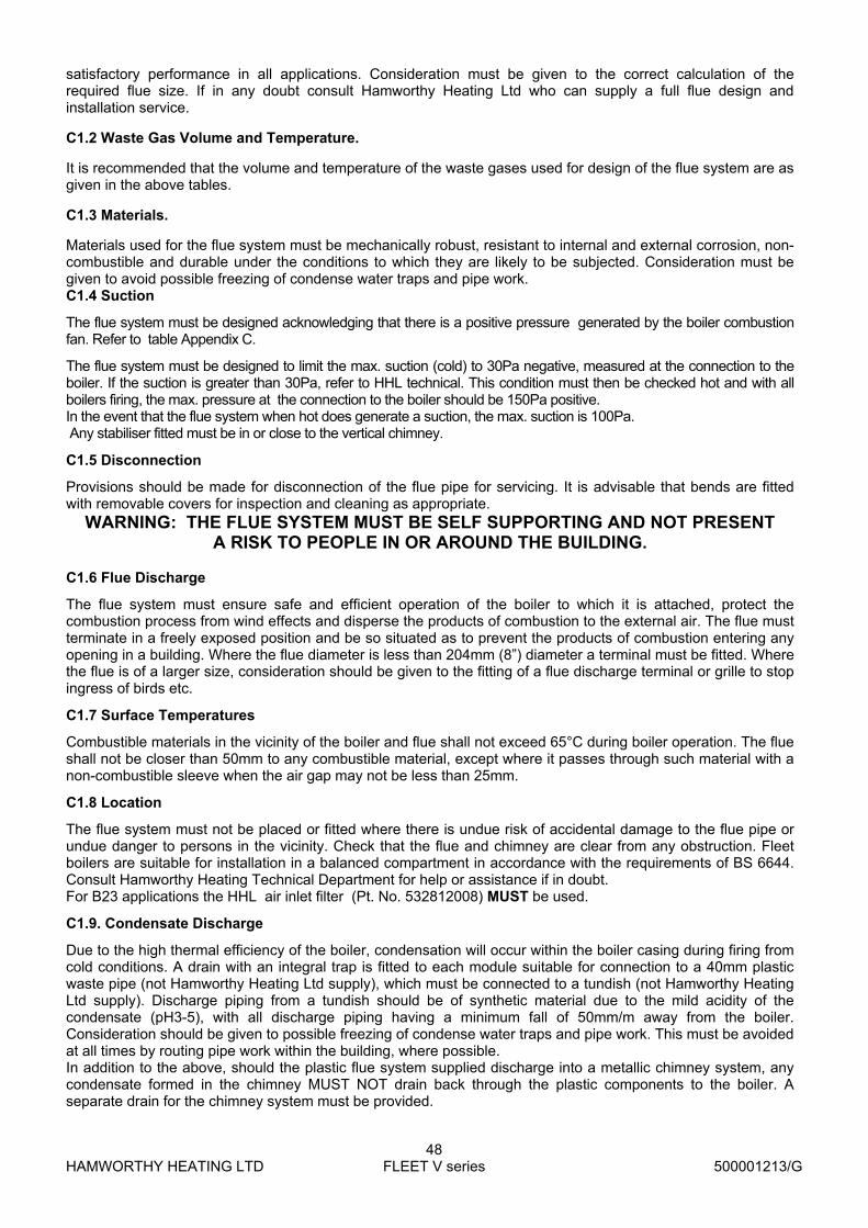
HAMWORTHY HEATING LTD
48 FLEET V series
500001213/G
satisfactory performance in all applications. Consideration must be given to the correct calculation of the required flue size. If in any doubt consult Hamworthy Heating Ltd who can supply a full flue design and installation service.
C1.2 Waste Gas Volume and Temperature. It is recommended that the volume and temperature of the waste gases used for design of the flue system are as given in the above tables.
C1.3 Materials. Materials used for the flue system must be mechanically robust, resistant to internal and external corrosion, non-combustible and durable under the conditions to which they are likely to be subjected. Consideration must be given to avoid possible freezing of condense water traps and pipe work. C1.4 Suction
The flue system must be designed acknowledging that there is a positive pressure generated by the boiler combustion fan. Refer to table Appendix C.
The flue system must be designed to limit the max. suction (cold) to 30Pa negative, measured at the connection to the boiler. If the suction is greater than 30Pa, refer to HHL technical. This condition must then be checked hot and with all boilers firing, the max. pressure at the connection to the boiler should be 150Pa positive. In the event that the flue system when hot does generate a suction, the max. suction is 100Pa. Any stabiliser fitted must be in or close to the vertical chimney.
C1.5 Disconnection
Provisions should be made for disconnection of the flue pipe for servicing. It is advisable that bends are fitted with removable covers for inspection and cleaning as appropriate.
WARNING: THE FLUE SYSTEM MUST BE SELF SUPPORTING AND NOT PRESENT A RISK TO PEOPLE IN OR AROUND THE BUILDING.
C1.6 Flue Discharge
The flue system must ensure safe and efficient operation of the boiler to which it is attached, protect the combustion process from wind effects and disperse the products of combustion to the external air. The flue must terminate in a freely exposed position and be so situated as to prevent the products of combustion entering any opening in a building. Where the flue diameter is less than 204mm (8”) diameter a terminal must be fitted. Where the flue is of a larger size, consideration should be given to the fitting of a flue discharge terminal or grille to stop ingress of birds etc.
C1.7 Surface Temperatures
Combustible materials in the vicinity of the boiler and flue shall not exceed 65°C during boiler operation. The flue shall not be closer than 50mm to any combustible material, except where it passes through such material with a non-combustible sleeve when the air gap may not be less than 25mm.
C1.8 Location
The flue system must not be placed or fitted where there is undue risk of accidental damage to the flue pipe or undue danger to persons in the vicinity. Check that the flue and chimney are clear from any obstruction. Fleet boilers are suitable for installation in a balanced compartment in accordance with the requirements of BS 6644. Consult Hamworthy Heating Technical Department for help or assistance if in doubt. For B23 applications the HHL air inlet filter (Pt. No. 532812008) MUST be used.
C1.9. Condensate Discharge
Due to the high thermal efficiency of the boiler, condensation will occur within the boiler casing during firing from cold conditions. A drain with an integral trap is fitted to each module suitable for connection to a 40mm plastic waste pipe (not Hamworthy Heating Ltd supply), which must be connected to a tundish (not Hamworthy Heating Ltd supply). Discharge piping from a tundish should be of synthetic material due to the mild acidity of the condensate (pH3-5), with all discharge piping having a minimum fall of 50mm/m away from the boiler. Consideration should be given to possible freezing of condense water traps and pipe work. This must be avoided at all times by routing pipe work within the building, where possible. In addition to the above, should the plastic flue system supplied discharge into a metallic chimney system, any condensate formed in the chimney MUST NOT drain back through the plastic components to the boiler. A separate drain for the chimney system must be provided.

HAMWORTHY HEATING LTD
49 FLEET V series
500001213/G
Figure C6.1 - Flue equivalent lengths
Flue Flue Equivalent lengths (m)
Load kW Diameter mm Max L 45° 90°
80 150 100 3 4
100 150 100 3 4
150 150 100 3 4
200 150 60 3 4
250 150 35 3 4
300 150 10 3 4
300 200 100 3 4
400 200 50 3 4
500 200 25 3 4
600 200 10 3 4
Accessory Descrip on HHL Part no
Flat roof flashing
150Ø 532511174
200Ø 532511175
Pitched roof flashing
150Ø universal(25‐45°) 532511178
200Ø (23‐ 27°) 532511179
200Ø (33‐ 47°) 532511180
200Ø (48 ‐ 52°) 532511181
Fixing brackets
150Ø 532511033
200Ø 532511186
Figure C6.2 - Flue Accessories
NOTE : For all B23 flue installations, the HHL supplied air inlet filter (Pt. No. 532812008) MUST be fitted
Air inlet
Rear view Side view
B23 Air Filter
B23 air inlet filter installed
In the instance that a B53 flue (ducted air inlet) is connected to a cascade (B23 outlet), the air inlet filters need not be fitted and therefore can be discarded.

HAMWORTHY HEATING LTD
50 FLEET V series
500001213/G
APPENDIX D - VENTILATION
D1.1 Air Supply
Detailed recommendations for air supply are given in BS 6644 and BS5440 Pt 2. The following notes are intended to give general guidance. In all cases there must be provision for an adequate supply of air for both combustion and general ventilation, in addition to that required for any other appliance. Note: For Open flue applications, combustion air for the boiler is drawn through the rear of the boiler casing. The air inlet must be kept open and free from blockage at all times.
D1.2 Air Supply by Natural Ventilation - Open Flue applications
The boiler room must have, or be provided with, permanent air vents directly to the outside air, at high and at low level. For an exposed boiler house, air vents should be fitted, preferably on all four sides, but at the least on two sides. Air vents should have negligible resistance and must not be sited in any position where they are likely to be easily blocked or flooded or in any position adjacent to an extraction system which is carrying flammable vapour. Grilles or louvres must be so designed that high velocity air streams do not occur within the vicinity of the boiler.
Boiler house ventilation
Low level (inlet) - 4cm² per kW of total rated input (Net) High level (output) - 2cm² per kW of total rated input (Net)
Compartment ventilation
Where the boiler is to be installed in a cupboard or compartment, permanent high and low level ventilation is required which must communicate direct to outside, for cooling purposes.
Low level (inlet) - 10cm² per kW of total rated input (Net) High level (output) - 5cm² per kW of total rated input (Net)
D1.3 Air Supply by Mechanical Ventilation
Air supplied to the boiler room by Mechanical means should be as follows: 1) Mechanical ventilation must be interlocked with the boilers to prevent operation in the event of ventilation fan failure 2) Mechanical inlet and mechanical extract can be utilised providing the design extraction rate does not exceed one third of the design inlet rate. 3) Mechanical extract ventilation with natural inlet ventilation MUST NOT be used.
Note * : Where the associated air extraction is also by means of a fan, this shall be selected such as not to cause a negative pressure to develop in the boiler house and to maintain the difference between inlet and extract flow rates shown. The calculated extract flow rate is the actual inlet flow rate minus the appropriate figure in the table above. For Mechanical ventilation systems an automatic control should be provided to cut off the gas supply to the boiler, in the event of failure of air flow in either inlet or extract fans.
D 1.4 Boiler House Temperatures
The air supplied for boiler house ventilation shall be such that the maximum temperatures within the boiler house shall be as follows:
At floor level (or 100mm above floor level) = 25°C. At mid-level (1.5m above floor level) = 32°C. At ceiling level (or 100mm below ceiling level) = 40°C.
D 1.5 General Requirements
The air supply should be free from contamination such as building dust and insulation fibres from lagging. To avoid unnecessary cleaning and servicing of the boiler modules, the boilers should not be fired whilst building work is being undertaken. High and low level ventilation grilles shall be positioned as high and as low as practicably possible. Low level grilles should be located within 1 metre of the floor for Natural Gas. High level grilles should be positioned within 15% of the boiler room height from the ceiling. High and low level grilles shall communicate with the same room or space where compartment ventilation is used. Where grilles communicate directly with outside air, they shall be positioned on the same wall.
Figure D1 Mechanical Ventilation Flow Rates
Flow rate per kW total rated heat input (Net) Inlet air
(Combustion ventilation)
Difference between Inlet & Extract air *
m³/h. m³/h. Volume 2.6 1.35

HAMWORTHY HEATING LTD
51 FLEET V series
500001213/G
APPENDIX E - WATER DATA
E1.1 Water Circulation System
The Fleet boiler has a low water content and the requirements of minimum water flow are given in the above table. To ensure these minimum requirements are achieved each boiler is fitted with an integral pump for circulation through the boiler and primary circuit supplemented by an integral flow switch. Recommendations for the water circulation system are given in BS 6644 and CP 342.
The following details are of particular importance for the correct installation of the water circulation system:
1) In a combined central heating and hot water system the hot water storage vessel must be of the indirect cylinder or calorifier type. The hot water storage vessel should be insulated, preferably with not less than 75mm (3”) thick mineral fibre, or its thermal equivalent.
2) Circulating pipe work not forming part of the useful heating surface should be insulated to help prevent heat loss and possible freezing, particularly where pipes are run through roof spaces and ventilated cavities. Cisterns situated in areas which may be exposed to freezing conditions should also be insulated. Furthermore, insulation exposed to the weather should be rendered waterproof.
3) Drain valves must be located in accessible positions which permit the draining of the whole system, including the boiler and hot water storage vessel.
4) Each boiler module has flow and return connections as detailed in the table above. Multiple boilers should be connected by flow and return headers. Hamworthy strongly recommend that boilers are connected in a primary circuit configuration utilising a low loss header arrangement to enable secondary circuits to be connected to the header. Figure E1.1.1 on the following page show typical layouts.
5) Ideally, individual valves should be fitted to each module to enable isolation from the system, however, the arrangement must comply with the requirements of BS 6644.
E1.2 Pressure Relief Valve (Safety Valve)
The most important single safety device fitted to a boiler is its safety valve. Each boiler module is provided with an integral safety valve terminating at the return pipe at the rear of the boiler. BS 6644 provides comprehensive information for the selection and location of safety valves and attention is drawn to the higher capacity requirements of safety valves for pressurised hot water systems.
E1.3 Altitude Gauge (Water Pressure Gauge)
Every boiler or group of boilers should be provided with an altitude gauge complete with isolating valve. See Figure E1.1.1 for typical position.
E1.4 Open Vent and Cold Feed Pipe.
Every boiler or group of boilers should have an open vent pipe and cold feed pipe installed between the boiler and the first water isolating valve. The minimum bore (mm) of these pipes per installation is shown in the table. The
WATER DATA - per module BOILER MODEL F40V F50V F60V F70V
Water connections (Flow & Return) - BSP R 1 1/4”
Maximum Water Pressure - bar g 6.0
Minimum Water Pressure - bar g
Water content (not including headers) - litres 4.0 4.0 5.0 5.0
Design Flow Rate @ 20°C ∆T Rise - litre/s 0.48 0.6 0.72 0.84
Waterside Pressure Loss @ 20°C ∆T Rise - mbar 70 80 80 100
0.5
Residual pump performance available - mbar 270 200 140 60
F85V F100V F125V F150V
Water connections (Flow & Return) - BSP R 1 1/4” Rp 11¼”
Maximum Water Pressure - bar g 6.0
Minimum Water Pressure - bar g
Water content (not including headers) - litres 6.0 6.0 7.0 8.0
Design Flow Rate @ 20°C ∆T Rise - litre/s 1.02 1.19 1.49 1.79
Waterside Pressure Loss @ 20°C ∆T Rise - mbar 100 110 140 400
0.5
Residual pump performance available - mbar 420 340 220 300

HAMWORTHY HEATING LTD
52 FLEET V series
500001213/G
vent pipe must rise continually, any valve fitted between a boiler and the open vent pipe for maintenance purposes shall be of the 3 way type such that when closed to the vent pipe the boiler will be open to atmosphere. The vent pipe shall be protected against freezing where this might occur. See BS 6644 for detailed information on Open Vent and Cold Feed Pipes.
E1.5 Thermometer
A thermometer complete with pocket should be fitted in the pipe work to indicate water flow temperature. See Figure E1.1.1 for typical position.
E1.6 Drain Valves
Each boiler has a 15mm NB drain valve fitted in the boiler return, for draining the boiler only. The heating system in total should have drain valves as recommended by BS 6644. See Figure E1.1.1 for typical position.
E1.7 Circulating Pump
Each individual boiler is fitted with an integral circulating pump ensuring flow through the boiler and primary circuit. To ensure the correct flow through the boiler, there is a balancing valve fitted to the flow pipe within the boiler. This is factory set and must not be adjusted. One or more circulating pumps will be required to circulate water around the heating system. All pumps should be sited to facilitate servicing. It is important that when Fleet boilers are used to replace boilers on an existing system, the system design must be modified acknowledging the performance of the integral circulating pump.. It is also important that the existing system be flushed through twice to remove any loose matter which may have accumulated. To protect the boiler heat exchanger, it is strongly recommended that a dirt/air separator is fitted in the return to the boiler. If in any doubt regarding the cleanliness of the system, a coarse filter should be fitted in the return pipe work to the boilers.
E1.8 Minimum Water Flow Rates
Minimum water flow rates are shown in table at beginning of Appendix E. These flow rates should be maintained through the boiler at all times whilst the boiler is firing. To prevent the boiler firing in the event of poor or no flow, the boiler is fitted with an integral flow switch. Particular attention should be paid to the restriction of external flow circuits during periods of low heat demand. Each boiler module is fitted with a flow balancing valve on the return pipe within the unit. This valve may require adjustment to ensure the correct flow through the boiler - refer to commissioning instructions Section 7.7
E1.9 Waterside Pressure Drop
The waterside hydraulic resistance (Pressure drop) is given in table at beginning of Appendix E.
E1.10 Water Flow Controls
The Fleet boiler is fitted with an integral circulating pump, which will shut off circulation 5 minutes after the boiler has ceased firing. Any external mixing valve / shunt pump or similar controls MUST always ensure that the minimum water flow rate as given in table at beginning of Appendix E is maintained. As a precaution, the Fleet boiler is fitted with a flow switch. The flow switch is designed to operate such that the boiler will shut down if insufficient flow occurs.
E1.11 Frost Protection
Consideration should be given to fitting an optional outside air sensor, to provide the necessary frost protection.
E1.12 Unvented Systems
Refer to Figure E1.1.1 on opposite page for typical layout of an unvented (Pressurised) Hot Water System. For system design refer to BS 7074 Part 2. In order to correctly size a pressurisation unit for any heating system the following parameters are required.
1) Static height of highest component in system (metres) 2) System volume. If this is not known, a general rule of thumb of 10litres/kW of installed boiler power
can be used. 3) Maximum flow temperature (°C) 4) Maximum system hot working pressure, generally given in bar gauge.
From the parameters given, Hamworthy Heating can size the pressurisation unit and also the expansion vessel. Care must be taken in sizing expansion vessels to ensure maximum acceptance factors are not exceeded. Normally manufacturers of vessels impose a limit of 0.5. This value must not be exceeded at any time during the operation of the boiler, this includes the over pressure condition should a safety valve lift. Consideration should also be given to sizing of the safety valve(s) in the system. Refer to BS 6759: Part 1 for further information and to BS 6880: Part 1 for design considerations.

HAMWORTHY HEATING LTD
53 FLEET V series
500001213/G
Figure E1.1 - Typical Piping Layouts
VENTED SYSTEM: Single pipe header
Mains water
Feedpipe
expansionFeed &
tank
valveFloatValve
Safetyvalve
Drain
Expansion pipePressure &
PgaugesTemperature
T
Module
Module
Hamworthy Modular Boilers
Hamworthy Modular Boilers
1
1
Module
Module
2
2
Module
Module
3
3
Valve
Circulation pump
Valve
(System)
Automatic
Heating load
Air Vent
Circulation pump
Drain
UNVENTED SYSTEM: Single pipe header
Temperaturegauges
Pressure &
Safetyvalve
P T
Heating load
AutomaticAir Vent
Valve
(System)
Valve
Lockshieldvalve
Mains water
Lockshieldvalve
Drainvalve
vessel
Temporaryfill line
valveLockshield
Double
valvecheck
Expansion
Air VentAutomatic
Valve
Drainvalve
valveDrain
Boiler Output Feed mm Vent mm
60 - 150kW 25 32
150 - 300 kW 32 38
300 - 600 kW 38 50
>601 KW 50 65
Figure E1.4 Cold Feed and Vent Pipe Sizes
E 1.13 Minimum System Water Pressure To comply with guidance note PM5 (Health and Safety Executive), the minimum pressure requirements at the boiler are given below as examples:-
1) Single installed boiler running at 82°C flow temperature. Minimum head required is not less than 2.0 metres or 0.2 bar.
2) Single installed boiler running at 90°C flow temperature. Minimum head required = 3.0 metres or 0.30 bar.
3) Modular boiler installation running at 82°C flow temperature and 11°C rise across system. Minimum head required = 4.4 metres or 0.43 bar.
4) Modular boiler installation running at 82°C flow temperature and 15°C rise across system. Minimum head required = 6.5 metres or 0.64 bar.

HAMWORTHY HEATING LTD
54 FLEET V series
500001213/G
Figure E1.7 - Integral pump performance curves
0 1
1
2
2
3
3
4
5
Q m /h3
Model
F 40W
F 50W
F 60W
F 70W
Model
F 85W
F 100W
F 125W
Model
F 150W
0.4
1.00 2.0 3.0 4.0 5.0 6.0
1.2
2.0
2.8
3.6
4.4
Head (m)
Head (m)
Head (m)
6.0
6.8
7.6
Q m /h3
max
max
Q m /h3
12
10
8
6
4
2
01.0 2.0 3.0 4.0 5.0 6.0

HAMWORTHY HEATING LTD
55 FLEET V series
500001213/G
Boiler1
Boiler1
Boiler1
Boiler1
Boiler2
Boiler2
Boiler2
Boiler2
Boiler3
Boiler3
Boiler3
Boiler3
HHL supplied close coupled single circuit low loss header
HHL supply
HHL supply
HHL supplied close coupled triple circuit low loss header
Non HHL supplied single circuit low loss header
Non HHL supplied plate heat exchanger separated system
AAV
Drain
Dosing Pot Note: - secondary circuit components are not suppliedwith the HHL pipe kit.
Note: - secondary circuit components are not suppliedwith the HHL pipe kit.
Dirt/ AirSeparator
Plate HeatExchanger
Filter
Flow
Flow
Flow
Flow
Flow
Flow
Return
Return
Return
Return
Return
Return
Figure E2 - Typical Pipe Kit system connections

HAMWORTHY HEATING LTD
56 FLEET V series
500001213/G
APPENDIX F - CASCADE CONTROL To Convert the boiler hydraulic diagram for cascade control Before programming changes are made, ensure the boiler is set to standby mode. Press and hold both up and down arrow keys for at least five seconds to enter advanced parameter list H90 displayed top right of HMI screen. Use either up or down arrow key to scroll through the parameter list and stop at H552
Option 1 - for use with the Merley sequence controller To enable cascade control change the setting by using the + or – key and set value to 80. Press mode button to store change and return to home screen.
Figure. F1

HAMWORTHY HEATING LTD
57 FLEET V series
500001213/G
NOTES :
HAMWORTHY HEATING LTD
58 FLEET V series
500001213/G
INSTALLER SITE ADDRESS
BOILER TYPE BOILER SIZE(S) UNIT NO(S). SERIAL NO(S). FLUE
USEFUL USER INFORMATION

Ple
ase
com
plet
e th
e in
form
atio
n on
the
Reg
istr
atio
n C
ard,
cut
out
and
ret
urn
to H
amw
orth
y H
eatin
g L
td.


Customer Service Centre Hamworthy Heating Limited, Fleets Corner, Poole, Dorset BH17 0HH Telephone: 0845 450 2866 Fax: 01202 662522 Email: [email protected] Website: www.hamworthy-heating.com Hamworthy reserves the right to make changes and improvements which may necessitate alteration to the specification without prior notice.
Hamworthy Heating Accredited Agents
North West England (Sales & Service)
Gillies Modular Services
210-218 New Chester Road, Birkenhead, Merseyside L41 9BG
tel: 0151 666 1030 fax: 0151 647 8101
Southern Ireland (Sales & Service)
HEVAC Limited
Naas Road, Dublin 12, Ireland
tel: 00 353 141 91919 fax: 00 353 145 84806
Northern Ireland (Sales & Service)
HVAC Supplies Limited
Unit A6, Dargan Court, Dargan Crescent, Belfast BT3 9JP
tel: 02890 747737 fax: 02890 741233
Scotland (Sales & Service)
McDowall Modular Services
14-46 Lomond Street, Glasgow, Scotland G22 6JD
tel: 0141 336 8795 fax: 0141 336 8954
North East England (Service)
Allison Heating Products
12 Sunnyside Lane, Cleadon Village, Sunderland SR6 7XB
tel: 0191 536 8833 fax: 0191 536 9933
Hamworthy Heating Customer Service Centre
Sales
tel: 0845 450 2865
Technical Enquiries
tel: 0845 450 2865
Servicing
tel: 01202 662555
Spares
tel: 0845 450 2866