flex 6000 gpsdo installation guide - gps central gpsdo installation guide.pdf · flex-6000 gpsdo...
TRANSCRIPT
Page 1 © 2013 FlexRadio Systems
FLEX-6000 GPSDO Installation Guide October 15, 2013
Thank you for purchasing the FLEX-6000 GPSDO Kit. The following guide will provide the necessary step-
by-step procedure for installing the FLEX-6000 GPSDO module.
Table of Contents
OBTAINING TECHNICAL SUPPORT ............................................................................................................... 2
GETTING STARTED ........................................................................................................................................... 2
Required Tools ........................................................................................................................................ 2
Packaging and GPSDO Kit Contents........................................................................................................ 2
PREPARING TO INSTALL THE GPSDO MODULE ......................................................................................... 3
Removing the Back Panel Metal Plugs ................................................................................................... 3
Removing the Chassis Feet .............................................................................................................. 5
Removing the Bottom Cover ................................................................................................................... 6
INSTALLING THE FLEX-6000 GPSDO ASSEMBLY ................................................................................................. 8
Installing the Internal Coax Cabling ........................................................................................................ 8
Installing the GPSDO Module Assembly ............................................................................................... 10
Reinstalling the Bottom Cover ..................................................................................................... 15
Reinstalling the Chassis Feet ........................................................................................................ 16
PREPARING THE GPSDO FOR FIRST USE ........................................................................................................... 18
Location Considerations for the FLEX-6000 .......................................................................................... 18
Installing the GPS Patch Antenna ......................................................................................................... 18
Enabling the GPSDO Module ................................................................................................................ 19
Verifying the Operation of the GPSDO Module .................................................................................... 20
Page 2 © 2013 FlexRadio Systems
Obtaining Technical Support
If you encounter any issues installing your FLEX-6000 accessory, please contact FlexRadio Systems
technical support by opening a HelpDesk ticket on-line at http://helpdesk.flexradio.com or by phone at +1
(512) 535-4713 extension #2. Please leave a voice mail message if you don’t get an answer as all of our
engineers are probably busy on existing calls.
Hours of Operation: Our Technical Support engineers are available Monday – Friday from 8:00am-5:30pm
Central Time. If you call after business hours, on a holiday or weekend, please leave a detailed message
and we will return your call during regular business hours in the order it was received.
You may always submit a HelpDesk support ticket at any time.
If you need assistance opening a HelpDesk ticket, please refer to the HelpDesk Assistance Center home
page for step-by-step instructions.
Getting Started
Required Tools
A number 2 (#2) Phillips Screwdriver
A 5/32” (4mm) nut driver or socket wrench
A 5/16” (8mm) open-ended wrench, nut driver or socket wrench
(The tools above are not supplied with the FLEX-6000 GPSDO module kit.)
TORX wrench (included)
Packaging and GPSDO Kit Contents
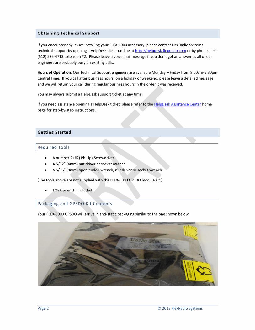
Your FLEX-6000 GPSDO will arrive in anti-static packaging similar to the one shown below.
Page 3 © 2013 FlexRadio Systems
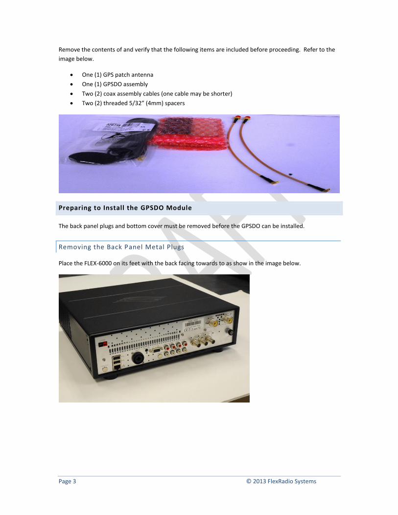
Remove the contents of and verify that the following items are included before proceeding. Refer to the
image below.
One (1) GPS patch antenna
One (1) GPSDO assembly
Two (2) coax assembly cables (one cable may be shorter)
Two (2) threaded 5/32” (4mm) spacers
Preparing to Install the GPSDO Module
The back panel plugs and bottom cover must be removed before the GPSDO can be installed.
Removing the Back Panel Metal Plugs
Place the FLEX-6000 on its feet with the back facing towards to as show in the image below.
Page 4 © 2013 FlexRadio Systems
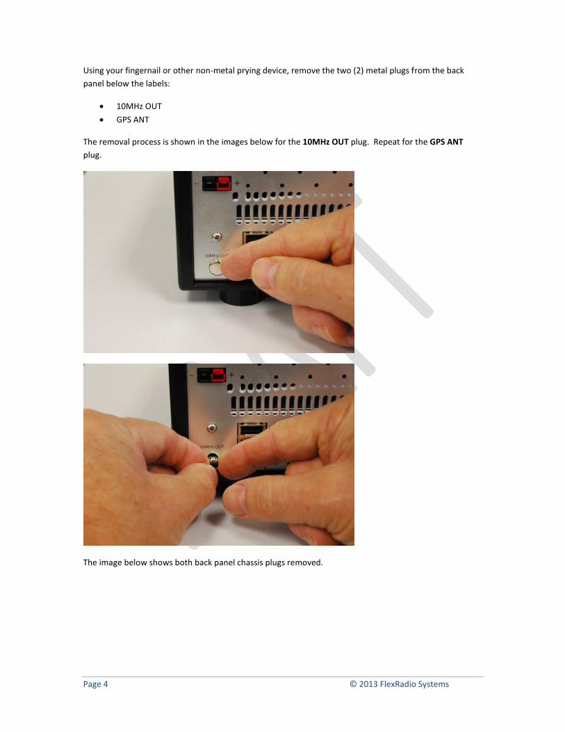
Using your fingernail or other non-metal prying device, remove the two (2) metal plugs from the back
panel below the labels:
10MHz OUT
GPS ANT
The removal process is shown in the images below for the 10MHz OUT plug. Repeat for the GPS ANT
plug.
The image below shows both back panel chassis plugs removed.
Page 5 © 2013 FlexRadio Systems
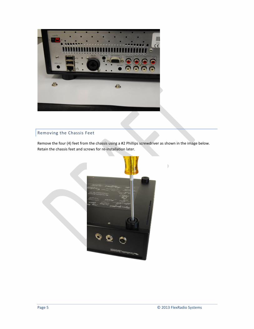
Removing the Chassis Feet
Remove the four (4) feet from the chassis using a #2 Phillips screwdriver as shown in the image below.
Retain the chassis feet and screws for re-installation later.
Page 6 © 2013 FlexRadio Systems
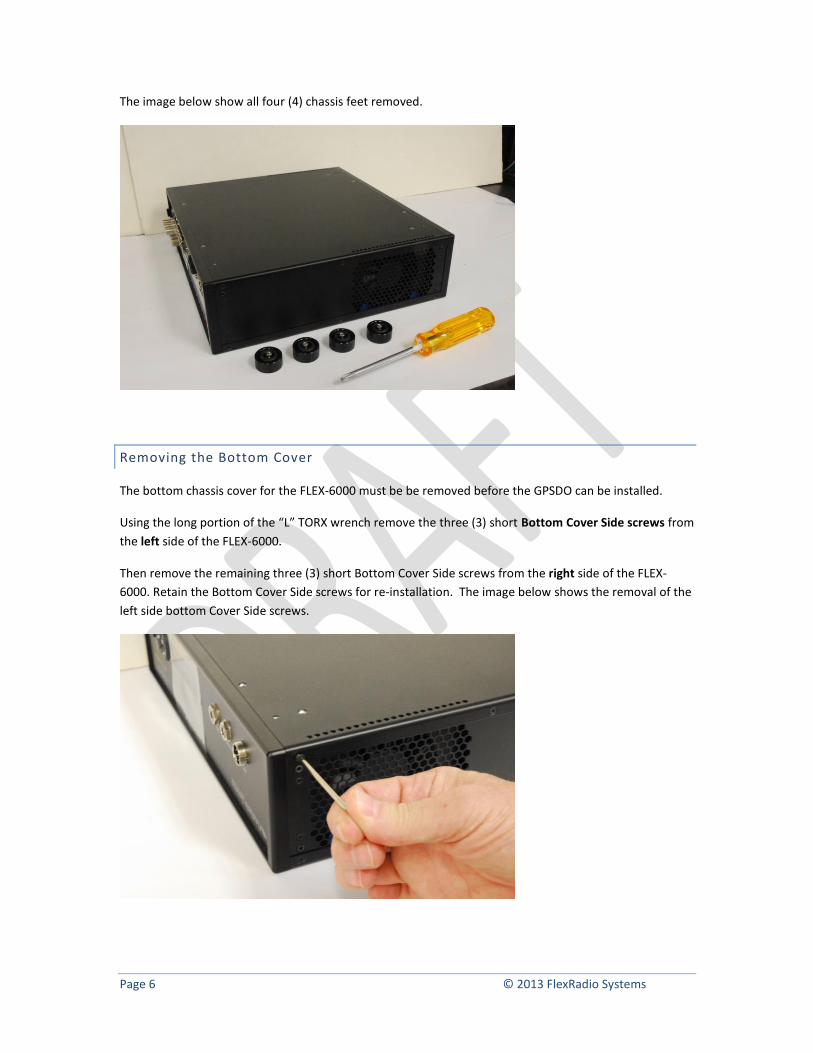
The image below show all four (4) chassis feet removed.
Removing the Bottom Cover
The bottom chassis cover for the FLEX-6000 must be be removed before the GPSDO can be installed.
Using the long portion of the “L” TORX wrench remove the three (3) short Bottom Cover Side screws from
the left side of the FLEX-6000.
Then remove the remaining three (3) short Bottom Cover Side screws from the right side of the FLEX-
6000. Retain the Bottom Cover Side screws for re-installation. The image below shows the removal of the
left side bottom Cover Side screws.
Page 7 © 2013 FlexRadio Systems
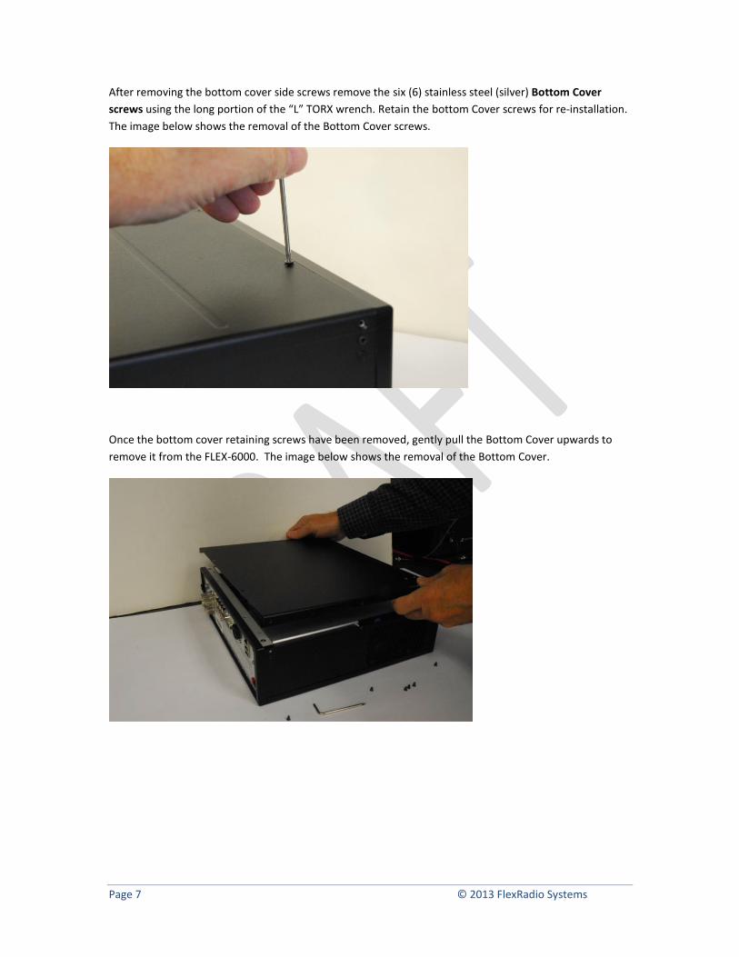
After removing the bottom cover side screws remove the six (6) stainless steel (silver) Bottom Cover
screws using the long portion of the “L” TORX wrench. Retain the bottom Cover screws for re-installation.
The image below shows the removal of the Bottom Cover screws.
Once the bottom cover retaining screws have been removed, gently pull the Bottom Cover upwards to
remove it from the FLEX-6000. The image below shows the removal of the Bottom Cover.
Page 8 © 2013 FlexRadio Systems
Installing the FLEX-6000 GPSDO Assembly
Once the bottom cover and chassis plugs have been removed, the GPSDO module can be installed onto
the FLEX-6000.
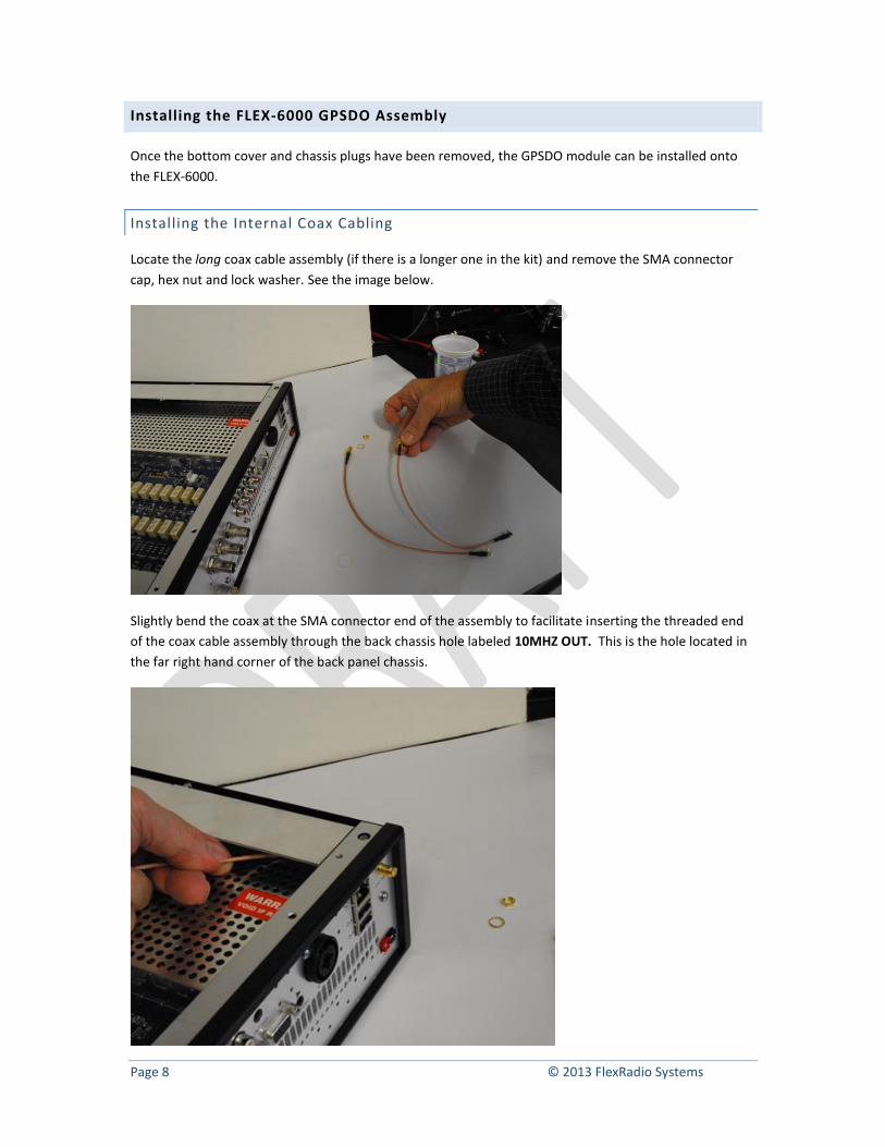
Installing the Internal Coax Cabling
Locate the long coax cable assembly (if there is a longer one in the kit) and remove the SMA connector
cap, hex nut and lock washer. See the image below.
Slightly bend the coax at the SMA connector end of the assembly to facilitate inserting the threaded end
of the coax cable assembly through the back chassis hole labeled 10MHZ OUT. This is the hole located in
the far right hand corner of the back panel chassis.
Page 9 © 2013 FlexRadio Systems
While firmly holding the long cable assembly in place with one hand, insert the lock washer on the
threaded SMA connector. Carefully install the SMA connector 5/16” (8 mm) hex nut on the threaded SMA
connector being careful not to cross thread the SMA connector. Tighten hex nut with your fingers so that
the coax cable assembly will freely rotate.
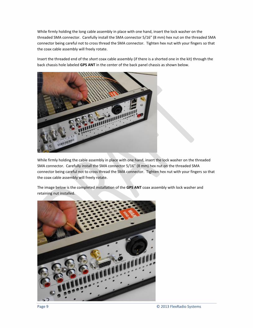
Insert the threaded end of the short coax cable assembly (if there is a shorted one in the kit) through the
back chassis hole labeled GPS ANT in the center of the back panel chassis as shown below.
While firmly holding the cable assembly in place with one hand, insert the lock washer on the threaded
SMA connector. Carefully install the SMA connector 5/16” (8 mm) hex nut on the threaded SMA
connector being careful not to cross thread the SMA connector. Tighten hex nut with your fingers so that
the coax cable assembly will freely rotate.
The image below is the completed installation of the GPS ANT coax assembly with lock washer and
retaining nut installed.
Page 10 © 2013 FlexRadio Systems
Installing the GPSDO Module Assembly
The next step is to install the actual GPSDO module assembly into the FLEX-6000.
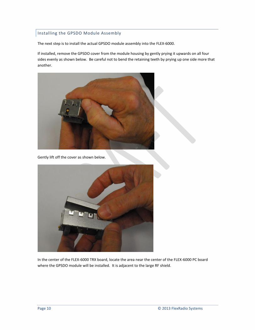
If installed, remove the GPSDO cover from the module housing by gently prying it upwards on all four
sides evenly as shown below. Be careful not to bend the retaining teeth by prying up one side more that
another.
Gently lift off the cover as shown below.
In the center of the FLEX-6000 TRX board, locate the area near the center of the FLEX-6000 PC board
where the GPSDO module will be installed. It is adjacent to the large RF shield.
Page 11 © 2013 FlexRadio Systems
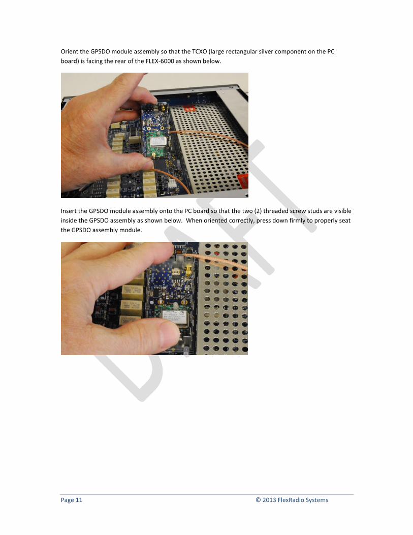
Orient the GPSDO module assembly so that the TCXO (large rectangular silver component on the PC
board) is facing the rear of the FLEX-6000 as shown below.
Insert the GPSDO module assembly onto the PC board so that the two (2) threaded screw studs are visible
inside the GPSDO assembly as shown below. When oriented correctly, press down firmly to properly seat
the GPSDO assembly module.
Page 12 © 2013 FlexRadio Systems
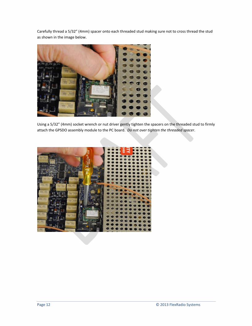
Carefully thread a 5/32” (4mm) spacer onto each threaded stud making sure not to cross thread the stud
as shown in the image below.
Using a 5/32” (4mm) socket wrench or nut driver gently tighten the spacers on the threaded stud to firmly
attach the GPSDO assembly module to the PC board. Do not over tighten the threaded spacer.
Page 13 © 2013 FlexRadio Systems
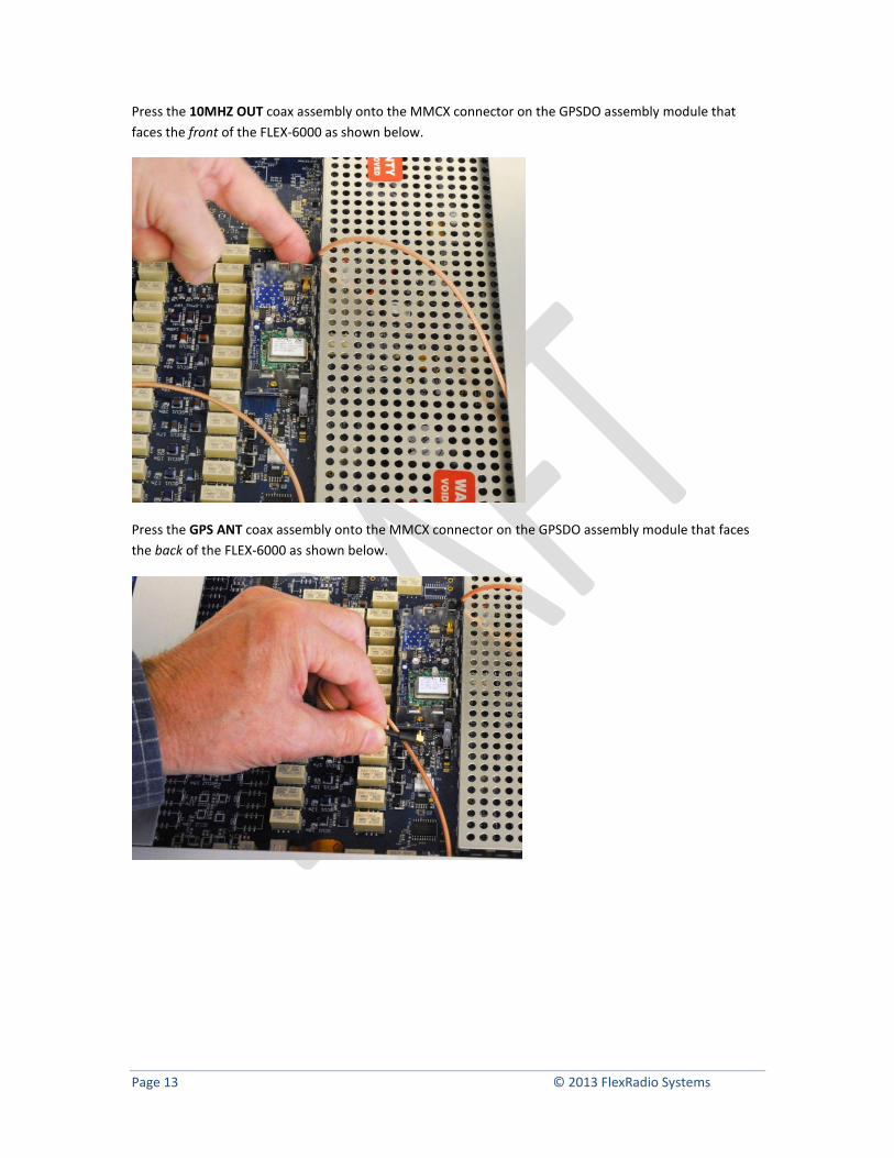
Press the 10MHZ OUT coax assembly onto the MMCX connector on the GPSDO assembly module that
faces the front of the FLEX-6000 as shown below.
Press the GPS ANT coax assembly onto the MMCX connector on the GPSDO assembly module that faces
the back of the FLEX-6000 as shown below.
Page 14 © 2013 FlexRadio Systems
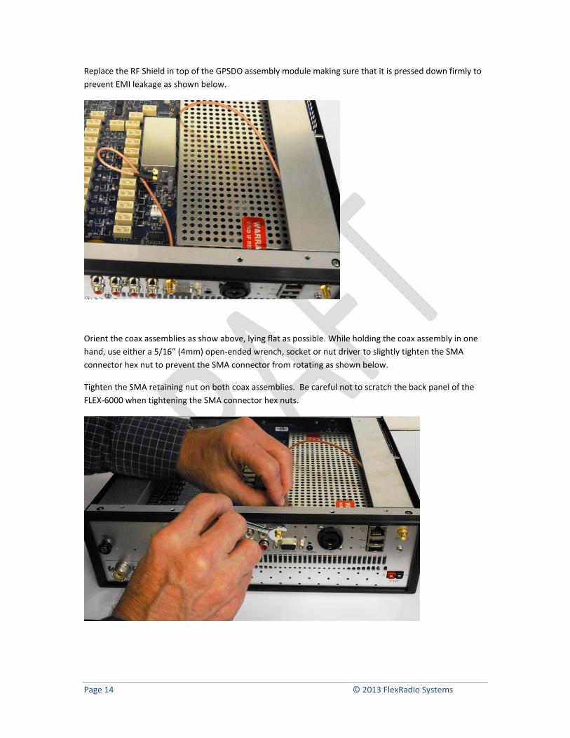
Replace the RF Shield in top of the GPSDO assembly module making sure that it is pressed down firmly to
prevent EMI leakage as shown below.
Orient the coax assemblies as show above, lying flat as possible. While holding the coax assembly in one
hand, use either a 5/16” (4mm) open-ended wrench, socket or nut driver to slightly tighten the SMA
connector hex nut to prevent the SMA connector from rotating as shown below.
Tighten the SMA retaining nut on both coax assemblies. Be careful not to scratch the back panel of the
FLEX-6000 when tightening the SMA connector hex nuts.
Page 15 © 2013 FlexRadio Systems
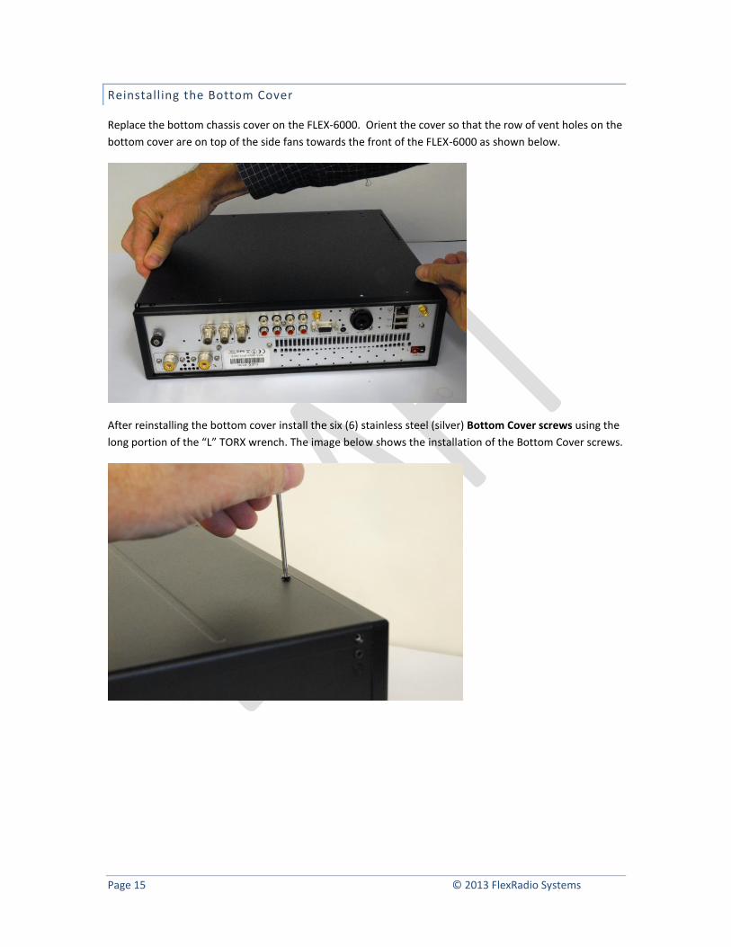
Reinstalling the Bottom Cover
Replace the bottom chassis cover on the FLEX-6000. Orient the cover so that the row of vent holes on the
bottom cover are on top of the side fans towards the front of the FLEX-6000 as shown below.
After reinstalling the bottom cover install the six (6) stainless steel (silver) Bottom Cover screws using the
long portion of the “L” TORX wrench. The image below shows the installation of the Bottom Cover screws.
Page 16 © 2013 FlexRadio Systems
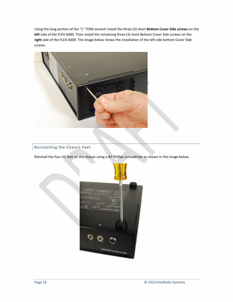
Using the long portion of the “L” TORX wrench install the three (3) short Bottom Cover Side screws on the
left side of the FLEX-6000. Then install the remaining three (3) short Bottom Cover Side screws on the
right side of the FLEX-6000. The image below shows the installation of the left side bottom Cover Side
screws.
Reinstalling the Chassis Feet
Reinstall the four (4) feet on the chassis using a #2 Phillips screwdriver as shown in the image below.
Page 17 © 2013 FlexRadio Systems
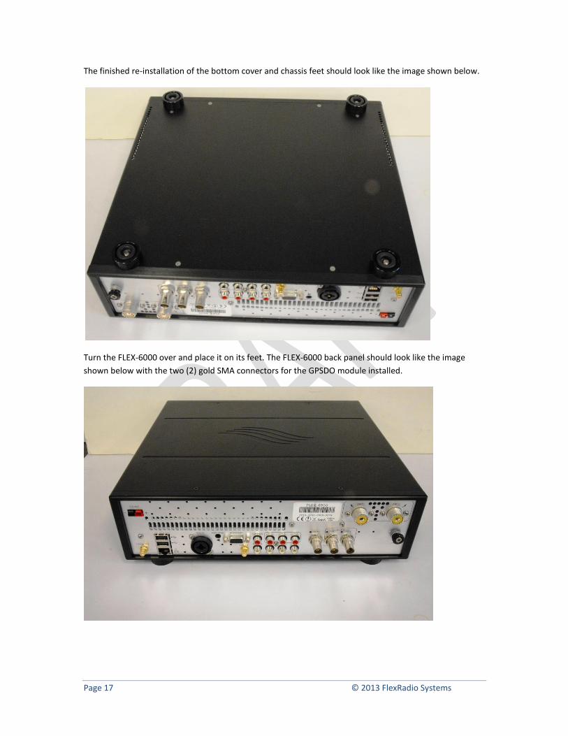
The finished re-installation of the bottom cover and chassis feet should look like the image shown below.
Turn the FLEX-6000 over and place it on its feet. The FLEX-6000 back panel should look like the image
shown below with the two (2) gold SMA connectors for the GPSDO module installed.
Page 18 © 2013 FlexRadio Systems
Preparing the GPSDO for First Use
Before using the GPSDO for the first time, the FLEX-6000 must be put back into its operating position and
the GPS patch antenna installed.
Location Considerations for the FLEX-6000
The supplied GPS “patch” antenna needs to be installed inside on a window that has a good view of the
horizon in order to receive the GPS signals from the geostationary satellites. This is required to discipline
the TCXO.
If the FLEX-6000’s operating position does not facilitate installing the GPS antenna as described above, an
external weatherproof GPS antenna will be required for proper operation.
Once a suitable location for the FLEX-6000 is found, install the FLEX-6000 in its operating position and
reconnect the Ethernet, DC power, Speaker and/or headphones, antennas and microphone and/or key.
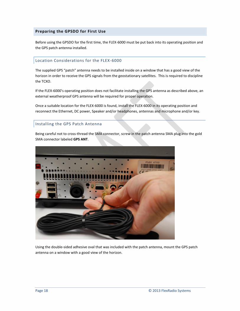
Installing the GPS Patch Antenna
Being careful not to cross-thread the SMA connector, screw in the patch antenna SMA plug into the gold
SMA connector labeled GPS ANT.
Using the double-sided adhesive oval that was included with the patch antenna, mount the GPS patch
antenna on a window with a good view of the horizon.
Page 19 © 2013 FlexRadio Systems
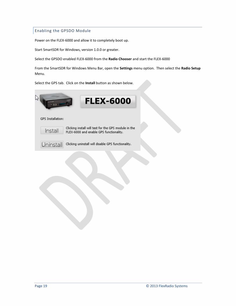
Enabling the GPSDO Module
Power on the FLEX-6000 and allow it to completely boot up.
Start SmartSDR for Windows, version 1.0.0 or greater.
Select the GPSDO enabled FLEX-6000 from the Radio Chooser and start the FLEX-6000
From the SmartSDR for Windows Menu Bar, open the Settings menu option. Then select the Radio Setup
Menu.
Select the GPS tab. Click on the Install button as shown below.
Page 20 © 2013 FlexRadio Systems
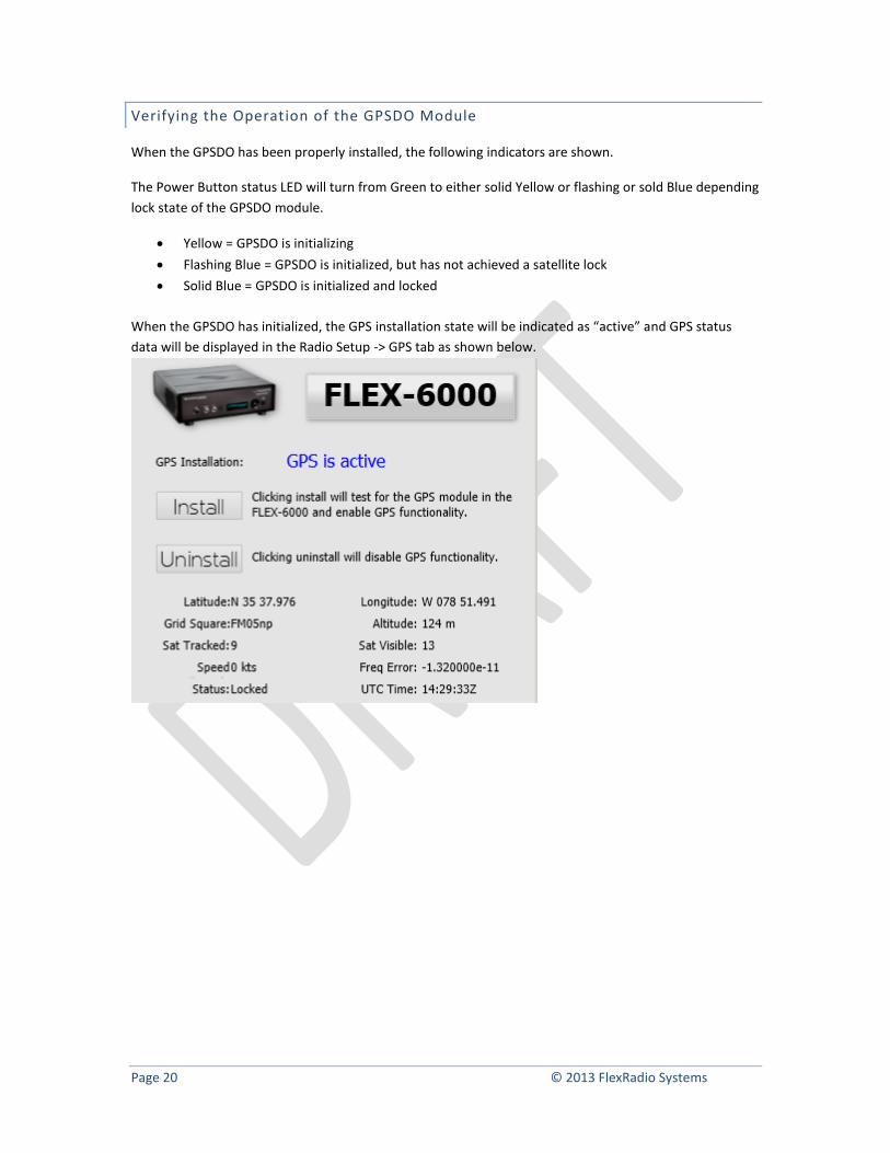
Verifying the Operation of the GPSDO Module
When the GPSDO has been properly installed, the following indicators are shown.
The Power Button status LED will turn from Green to either solid Yellow or flashing or sold Blue depending
lock state of the GPSDO module.
Yellow = GPSDO is initializing
Flashing Blue = GPSDO is initialized, but has not achieved a satellite lock
Solid Blue = GPSDO is initialized and locked
When the GPSDO has initialized, the GPS installation state will be indicated as “active” and GPS status
data will be displayed in the Radio Setup -> GPS tab as shown below.