flex tech building lccc flex laramie...
TRANSCRIPT
FLEX TECH BUILDING LCCC_FLEX LARAMIE COUNTY COMMUNITY COLLEGE CONSTRUCTION DOCUMENTS CHEYENNE, WY MAY 1, 2015
CERAMIC TILING 093013 - 1
SECTION 093013 - CERAMIC TILING
PART 1 - GENERAL
1.1 SUMMARY
A. Section Includes:
1. Ceramic mosaic tile. 2. Porcelain tile.
1.2 ACTION SUBMITTALS
A. Product Data: For each type of product.
B. Samples:
1. Each type and composition of tile and for each color and finish required.
1.3 INFORMATIONAL SUBMITTALS
A. Qualification Data: For Installer.
1.4 MAINTENANCE MATERIAL SUBMITTALS
A. Furnish extra materials that match and are from same production runs as products installed and that are packaged with protective covering for storage and identified with labels describing contents.
1. Tile and Trim Units: Furnish quantity of full-size units equal to 3 percent of amount installed for each type, composition, color, pattern, and size indicated.
1.5 QUALITY ASSURANCE
A. Installer Qualifications:
1. Installer employs Ceramic Tile Education Foundation Certified Installers.
B. Mockups: Build mockups to verify selections made under Sample submittals and to demonstrate aesthetic effects and set quality standards for materials and execution.
1. Build mockup of tile installation that represents all corner and edge conditions. 2. Subject to compliance with requirements, approved mockups may become part of the
completed Work if undisturbed at time of Substantial Completion.
FLEX TECH BUILDING LCCC_FLEX LARAMIE COUNTY COMMUNITY COLLEGE CONSTRUCTION DOCUMENTS CHEYENNE, WY MAY 1, 2015
CERAMIC TILING 093013 - 2
PART 2 - PRODUCTS
2.1 PRODUCTS, GENERAL
A. ANSI Ceramic Tile Standard: Provide Standard-grade tile that complies with ANSI A137.1 for types, compositions, and other characteristics indicated.
B. ANSI Standards for Tile Installation Materials: Provide materials complying with ANSI A108.02, ANSI standards referenced in other Part 2 articles, ANSI standards referenced by TCNA installation methods specified in tile installation schedules, and other requirements specified.
2.2 TILE PRODUCTS
A. Basis-of-Design Manufacturer: Subject to compliance with requirements, provide products by Daltile or comparable product by other if approved by Addendum:
B. Ceramic Tile Type FT1: Factory-mounted unglazed ceramic mosaic tile.
1. Basis-of-Design Product: Keystones Mosaics D109 Architectural Gray. 2. Composition: Porcelain. 3. Certification: Porcelain tile certified by the Porcelain Tile Certification Agency. 4. Module Size: 1 by 1 inch. 5. Thickness: 1/4 inch. 6. Face: Plain with cushion edges. 7. Surface: Smooth, without abrasive admixture. 8. Dynamic Coefficient of Friction: Not less than 0.42. 9. Finish: Mat, opaque glaze. 10. Grout Color: As selected by Architect from manufacturer's full range.
C. Ceramic Tile Type WT1: Glazed porcelain tile.
1. Basis-of-Design Product: Semigloss Biscuit K175. 2. Certification: Tile certified by the Porcelain Tile Certification Agency. 3. Face Size: 3 by 6 inches. 4. Face Size Variation: Rectified. 5. Thickness: 1/4 inch. 6. Face: Plain with cushion edges. 7. Grout Color: As selected by Architect from manufacturer's full range. 8. Trim Units: Coordinated with sizes and coursing of adjoining flat tile where
applicable and matching characteristics of adjoining flat tile. Provide shapes as follows, selected from manufacturer's standard shapes:
a. Base and Wainscot Cap: Surface bullnose, module size same as adjoining flat tile. b. External Corners: Surface bullnose, module size same as adjoining flat tile.
D. Fiber-Cement Backer Board: ASTM C 1288.

FLEX TECH BUILDING LCCC_FLEX LARAMIE COUNTY COMMUNITY COLLEGE CONSTRUCTION DOCUMENTS CHEYENNE, WY MAY 1, 2015
CERAMIC TILING 093013 - 3
1. Manufacturers: Subject to compliance with requirements, available manufacturers offering products that may be incorporated into the Work include, but are not limited to, the following:
a. CertainTeed Corporation. b. James Hardie Building Products, Inc.
2. Thickness: 1/2 inch.
2.3 SETTING MATERIALS
A. Latex-Portland Cement Mortar (Thinset): ANSI A118.4.
1. Manufacturers: Subject to compliance with requirements, available manufacturers offering products that may be incorporated into the Work include, but are not limited to, the following:
a. Custom Building Products. b. Laticrete International, Inc. c. MAPEI Corporation. d. TEC; H.B. Fuller Construction Products Inc.
2. Provide prepackaged, dry-mortar mix to which only water must be added at Project site. 3. For wall applications, provide nonsagging mortar.
2.4 GROUT MATERIALS
A. Water-Cleanable Epoxy Grout: ANSI A118.3.
1. Basis-of-Design Product: Subject to compliance with requirements, provide Laticrete SpectraLock Pro Grout or comparable product by one of the following:
a. Laticrete International, Inc. b. MAPEI Corporation. c. TEC; H.B. Fuller Construction Products Inc.
2.5 MISCELLANEOUS MATERIALS
A. Trowelable Underlayments and Patching Compounds: Latex-modified, portland cement-based formulation provided or approved by manufacturer of tile-setting materials for installations indicated.
B. Metal Edge Strips: Basis-of-Design, subject to compliance with requirements, provide Schluter Systems or comparable products if approved by Addendum.
1. Shapes: DILEX-AHKA, DILEX-AHK/-PHK, RENO-U or as indicated on Drawings. 2. Size: Suitable for thickness of tile.
FLEX TECH BUILDING LCCC_FLEX LARAMIE COUNTY COMMUNITY COLLEGE CONSTRUCTION DOCUMENTS CHEYENNE, WY MAY 1, 2015
CERAMIC TILING 093013 - 4
3. Finish: Clear anodized aluminum.
PART 3 - EXECUTION
3.1 EXAMINATION
A. Examine substrates, areas, and conditions where tile will be installed, with Installer present, for compliance with requirements for installation tolerances and other conditions affecting performance of the Work.
1. Verify that substrates for setting tile are firm; dry; clean; free of coatings that are incompatible with tile-setting materials, including curing compounds and other substances that contain soap, wax, oil, or silicone; and comply with flatness tolerances required by ANSI A108.01 for installations indicated.
2. Verify that concrete substrates for tile floors installed with thinset mortar comply with surface finish requirements in ANSI A108.01 for installations indicated.
B. Proceed with installation only after unsatisfactory conditions have been corrected.
3.2 PREPARATION
A. Fill cracks, holes, and depressions in concrete substrates for tile floors installed with thinset mortar with trowelable leveling and patching compound specifically recommended by tile-setting material manufacturer.
B. Blending: For tile exhibiting color variations, verify that tile has been factory blended and packaged so tile units taken from one package show same range of colors as those taken from other packages and match approved Samples. If not factory blended, either return to manufacturer or blend tiles at Project site before installing.
3.3 CERAMIC TILE INSTALLATION
A. Comply with TCNA's "Handbook for Ceramic, Glass, and Stone Tile Installation" for TCNA installation methods specified in tile installation schedules. Comply with parts of the ANSI A108 series "Specifications for Installation of Ceramic Tile" that are referenced in TCNA installation methods, specified in tile installation schedules, and apply to types of setting and grouting materials used.
1. For the following installations, follow procedures in the ANSI A108 series of tile installation standards for providing 95 percent mortar coverage:
a. Tile floors in wet areas.
B. Terminate work neatly at obstructions, edges, and corners without disrupting pattern or joint alignments.

FLEX TECH BUILDING LCCC_FLEX LARAMIE COUNTY COMMUNITY COLLEGE CONSTRUCTION DOCUMENTS CHEYENNE, WY MAY 1, 2015
CERAMIC TILING 093013 - 5
C. Accurately form intersections and returns. Perform cutting and drilling of tile without marring visible surfaces. Carefully grind cut edges of tile abutting trim, finish, or built-in items for straight aligned joints. Fit tile closely to electrical outlets, piping, fixtures, and other penetrations so plates, collars, or covers overlap tile.
D. Provide manufacturer's standard trim shapes where necessary to eliminate exposed tile edges.
E. Where accent tile differs in thickness from field tile, vary setting bed thickness so that tiles are flush.
F. Jointing Pattern: Lay tile in grid pattern unless otherwise indicated. Lay out tile work and center tile fields in both directions in each space or on each wall area. Lay out tile work to minimize the use of pieces that are less than half of a tile. Provide uniform joint widths unless otherwise indicated.
G. Joint Widths: Unless otherwise indicated, install tile as follows.
1. Mosaic tile with approximately 1/8 inch joint widths. 2. Wall tile with approximately 1/16 inch joint widths.
H. Lay out tile wainscots to dimensions indicated or to next full tile beyond dimensions indicated.
3.4 INTERIOR CERAMIC TILE INSTALLATION SCHEDULE
A. Interior Floor Installations, Concrete Subfloor:
1. Ceramic Tile Installation: TCNA F113; thinset mortar.
a. Thinset Mortar: Latex portland cement mortar.
2. Grout: Water-cleanable epoxy grout.
B. Interior Wall Installations, Wood or Metal Studs or Furring:
1. Ceramic Tile Installation: TCNA W244C or TCNA W244F; thinset mortar on cementitious backer units or fiber-cement backer board.
a. Thinset Mortar: Latex-portland cement mortar. b. Grout: Water-cleanable epoxy grout.
END OF SECTION 093013
FLEX TECH BUILDING LCCC_FLEX LARAMIE COUNTY COMMUNITY COLLEGE CONSTRUCTION DOCUMENTS CHEYENNE, WY MAY 1, 2015
GENERAL-DUTY VALVES FOR PLUMBING PIPING 220523 - 1
SECTION 220523 - GENERAL-DUTY VALVES FOR PLUMBING PIPING
PART 1 - GENERAL
1.1 SUMMARY
A. Section Includes:
1. Bronze ball valves. 2. Iron ball valves. 3. Iron, single-flange butterfly valves. 4. Iron, grooved-end butterfly valves. 5. Bronze swing check valves. 6. Iron swing check valves. 7. Iron, grooved-end swing check valves. 8. Iron, center-guided check valves.
B. Related Sections:
1. Section 220553 "Identification for Plumbing Piping and Equipment" for valve tags and schedules.
2. Section 221116 "Domestic Water Piping" for valves applicable only to this piping. 3. Section 221319 "Sanitary Waste Piping Specialties" for valves applicable only to this
piping. 4. Section 221423 "Storm Drainage Piping Specialties" for valves applicable only to this
piping.
1.2 DEFINITIONS
A. CWP: Cold working pressure.
B. EPDM: Ethylene propylene copolymer rubber.
C. Lead Free: Refers to the wetted surface of pipe, fittings and fixtures in potable water systems that have a weighted average lead content ≤0.25% per Safe Drinking Water Act.
D. NRS: Nonrising stem.
1.3 ACTION SUBMITTALS
A. Product Data: For each type of valve indicated.

FLEX TECH BUILDING LCCC_FLEX LARAMIE COUNTY COMMUNITY COLLEGE CONSTRUCTION DOCUMENTS CHEYENNE, WY MAY 1, 2015
GENERAL-DUTY VALVES FOR PLUMBING PIPING 220523 - 2
1.4 QUALITY ASSURANCE
A. Source Limitations for Valves: Obtain each type of valve from single source from single manufacturer.
B. ASME Compliance:
1. ASME B16.10 and ASME B16.34 for ferrous valve dimensions and design criteria. 2. ASME B31.9 for building services piping valves.
C. NSF Compliance: NSF 61 for valve materials for potable-water service. NSF/ANSI-372 for lead free valves.
1.5 DELIVERY, STORAGE, AND HANDLING
A. Prepare valves for shipping as follows:
1. Protect internal parts against rust and corrosion. 2. Protect threads, flange faces, grooves, and weld ends. 3. Set ball valves open to minimize exposure of functional surfaces. 4. Set butterfly valves closed or slightly open. 5. Block check valves in either closed or open position.
B. Use the following precautions during storage:
1. Maintain valve end protection. 2. Store valves indoors and maintain at higher than ambient dew point temperature. If
outdoor storage is necessary, store valves off the ground in watertight enclosures.
C. Use sling to handle large valves; rig sling to avoid damage to exposed parts. Do not use handwheels or stems as lifting or rigging points.
PART 2 - PRODUCTS
2.1 GENERAL REQUIREMENTS FOR VALVES
A. Refer to valve schedule articles for applications of valves.
B. All valves shall be Lead Free (ASTM listed) and shall be made with corrosion-resistant materials. Manufacturer shall provide upon request third party certification tested in accordance with EN ISO 6509 regarding dezincification corrosion resistance and stress corrosion cracking.
C. Valve Pressure and Temperature Ratings: Not less than indicated and as required for system pressures and temperatures.
D. Valve Sizes: Same as upstream piping unless otherwise indicated.
E. Valve Actuator Types:

FLEX TECH BUILDING LCCC_FLEX LARAMIE COUNTY COMMUNITY COLLEGE CONSTRUCTION DOCUMENTS CHEYENNE, WY MAY 1, 2015
GENERAL-DUTY VALVES FOR PLUMBING PIPING 220523 - 3
1. Handwheel: For valves other than quarter-turn types.
F. Handlever: For quarter-turn valves NPS 6 and smallerValves in Insulated Piping: With 2-inch stem extensions and the following features:
1. Ball Valves: With extended operating handle of non-thermal-conductive material, and protective sleeve that allows operation of valve without breaking the vapor seal or disturbing insulation.
2. Butterfly Valves: With extended neck.
G. Valve-End Connections:
1. Flanged: With flanges according to ASME B16.1 for iron valves. 2. Grooved: With grooves according to AWWA C606. 3. Solder Joint: With sockets according to ASME B16.18. 4. Threaded: With threads according to ASME B1.20.1.
H. Valve Bypass and Drain Connections: MSS SP-45.
2.2 BRONZE BALL VALVES
A. Two-Piece, Full-Port, Bronze Ball Valves with Bronze Trim:
1. Manufacturers: Subject to compliance with requirements available manufacturers offering products that may be incorporated into the Work include, but are not limited to, the following:
a. American Valve, Inc. b. Conbraco Industries, Inc.; Apollo Valves. c. Crane Co.; Crane Valve Group; Crane Valves. d. Hammond Valve. e. Lance Valves; a division of Advanced Thermal Systems, Inc. f. Legend Valve. g. Milwaukee Valve Company. h. NIBCO INC. i. Red-White Valve Corporation. j. Watts Regulator Co.; a division of Watts Water Technologies, Inc.
2. Description:
a. Standard: MSS SP-110. b. SWP Rating: 150 psig. c. CWP Rating: 600 psig. d. Body Design: Two piece. e. Body Material: ASTM B61, B62 or B584 Bronze. f. Ends: Threaded. g. Seats: PTFE or TFE. h. Stem: Bronze. i. Ball: Chrome-plated brass.
FLEX TECH BUILDING LCCC_FLEX LARAMIE COUNTY COMMUNITY COLLEGE CONSTRUCTION DOCUMENTS CHEYENNE, WY MAY 1, 2015
GENERAL-DUTY VALVES FOR PLUMBING PIPING 220523 - 4
j. Port: Full. k. All components shall be "Dezincification Resistant." l. All components shall be certified "Lead-Free."
2.3 IRON BALL VALVES
A. Class 125, Iron Ball Valves:
1. Manufacturers: Subject to compliance with requirements, available manufacturers offering products that may be incorporated into the Work include, but are not limited to, the following:
a. American Valve, Inc. b. Conbraco Industries, Inc.; Apollo Valves. c. Kitz Corporation. d. Sure Flow Equipment Inc. e. Watts Regulator Co.; a division of Watts Water Technologies, Inc.
2. Description:
a. Standard: MSS SP-72. b. CWP Rating: 200 psig. c. Body Design: Split body. d. Body Material: ASTM A 126, gray iron. e. Ends: Flanged. f. Seats: PTFE or TFE. g. Stem: Stainless steel. h. Ball: Stainless steel. i. Port: Full. j. All components shall be certified "Lead-Free."
2.4 IRON, SINGLE-FLANGE BUTTERFLY VALVES
A. 200 CWP, Iron, Single-Flange Butterfly Valves with EPDM Seat and Aluminum-Bronze Disc:
1. Manufacturers: Subject to compliance with requirements, available manufacturers offering products that may be incorporated into the Work include, but are not limited to, the following:
a. ABZ Valve and Controls; a division of ABZ Manufacturing, Inc. b. Conbraco Industries, Inc.; Apollo Valves. c. Cooper Cameron Valves; a division of Cooper Cameron Corporation. d. Crane Co.; Crane Valve Group; Jenkins Valves. e. Crane Co.; Crane Valve Group; Stockham Division. f. DeZurik Water Controls. g. Flo Fab Inc. h. Hammond Valve. i. Kitz Corporation.

FLEX TECH BUILDING LCCC_FLEX LARAMIE COUNTY COMMUNITY COLLEGE CONSTRUCTION DOCUMENTS CHEYENNE, WY MAY 1, 2015
GENERAL-DUTY VALVES FOR PLUMBING PIPING 220523 - 5
j. Legend Valve. k. Milwaukee Valve Company. l. NIBCO INC. m. Norriseal; a Dover Corporation company. n. Red-White Valve Corporation. o. Spence Strainers International; a division of CIRCOR International, Inc. p. Watts Regulator Co.; a division of Watts Water Technologies, Inc.
2. Description:
a. Standard: MSS SP-67, Type I. b. CWP Rating: 200 psig. c. Body Design: Lug type; suitable for bidirectional dead-end service at rated
pressure without use of downstream flange. d. Body Material: ASTM A 126, cast iron or ASTM A 536, ductile iron. e. Seat: EPDM. f. Stem: One- or two-piece stainless steel. g. Disc: Aluminum bronze. h. All components shall be certified "Lead-Free."
2.5 IRON, GROOVED-END BUTTERFLY VALVES
A. 175 CWP, Iron, Grooved-End Butterfly Valves:
1. Manufacturers: Subject to compliance with requirements, available manufacturers offering products that may be incorporated into the Work include, but are not limited to, the following:
a. Kennedy Valve; a division of McWane, Inc. b. Shurjoint Piping Products. c. Tyco Fire Products LP; Grinnell Mechanical Products. d. Victaulic Company.
2. Description:
a. Standard: MSS SP-67, Type I. b. CWP Rating: 175 psig. c. Body Material: Coated, ductile iron. d. Stem: Two-piece stainless steel. e. Disc: Coated, ductile iron. f. Seal: EPDM. g. All components shall be certified "Lead-Free."
2.6 BRONZE SWING CHECK VALVES
A. Class 150, Bronze Swing Check Valves with Bronze Disc:

FLEX TECH BUILDING LCCC_FLEX LARAMIE COUNTY COMMUNITY COLLEGE CONSTRUCTION DOCUMENTS CHEYENNE, WY MAY 1, 2015
GENERAL-DUTY VALVES FOR PLUMBING PIPING 220523 - 6
1. Manufacturers: Subject to compliance with requirements, available manufacturers offering products that may be incorporated into the Work include, but are not limited to, the following:
a. American Valve, Inc. b. Crane Co.; Crane Valve Group; Crane Valves. c. Crane Co.; Crane Valve Group; Jenkins Valves. d. Crane Co.; Crane Valve Group; Stockham Division. e. Kitz Corporation. f. Milwaukee Valve Company. g. NIBCO INC. h. Red-White Valve Corporation. i. Zy-Tech Global Industries, Inc.
2. Description:
a. Standard: MSS SP-80, Type 3. b. CWP Rating: 300 psig. c. Body Design: Horizontal flow. d. Body Material: ASTM B61, B62, or B584 bronze. e. Ends: Threaded. f. Disc: Bronze. g. All components shall be "Dezincification Resistant." h. All components shall be certified "Lead-Free."
2.7 IRON SWING CHECK VALVES
A. Class 125, Iron Swing Check Valves with Metal Seats:
1. Manufacturers: Subject to compliance with requirements, available manufacturers offering products that may be incorporated into the Work include, but are not limited to, the following:
a. Crane Co.; Crane Valve Group; Crane Valves. b. Crane Co.; Crane Valve Group; Jenkins Valves. c. Crane Co.; Crane Valve Group; Stockham Division. d. Hammond Valve. e. Kitz Corporation. f. Legend Valve. g. Milwaukee Valve Company. h. NIBCO INC. i. Powell Valves. j. Red-White Valve Corporation. k. Sure Flow Equipment Inc. l. Watts Regulator Co.; a division of Watts Water Technologies, Inc. m. Zy-Tech Global Industries, Inc.
2. Description:

FLEX TECH BUILDING LCCC_FLEX LARAMIE COUNTY COMMUNITY COLLEGE CONSTRUCTION DOCUMENTS CHEYENNE, WY MAY 1, 2015
GENERAL-DUTY VALVES FOR PLUMBING PIPING 220523 - 7
a. Standard: MSS SP-71, Type I. b. CWP Rating: 200 psig. c. Body Design: Clear or full waterway. d. Body Material: ASTM A 126, gray iron with bolted bonnet. e. Ends: Flanged. f. Trim: Bronze. g. Gasket: Asbestos free. h. All components shall be certified "Lead-Free."
2.8 IRON, GROOVED-END SWING CHECK VALVES
A. 300 CWP, Iron, Grooved-End Swing Check Valves:
1. Manufacturers: Subject to compliance with requirements, available manufacturers offering products that may be incorporated into the Work include, but are not limited to, the following:
a. Anvil International, Inc. b. Shurjoint Piping Products. c. Tyco Fire Products LP; Grinnell Mechanical Products. d. Victaulic Company.
2. Description:
a. CWP Rating: 300 psig. b. Body Material: ASTM A 536, ductile iron. c. Seal: EPDM. d. Disc: Spring-operated, ductile iron or stainless steel. e. All components shall be certified "Lead-Free."
2.9 IRON, CENTER-GUIDED CHECK VALVES
A. Class 125, Iron, Compact-Wafer, Center-Guided Check Valves with Metal Seat:
1. Manufacturers: Subject to compliance with requirements, available manufacturers offering products that may be incorporated into the Work include, but are not limited to, the following:
a. Anvil International, Inc. b. APCO Willamette Valve and Primer Corporation. c. Crispin Valve. d. DFT Inc. e. Flo Fab Inc. f. GA Industries, Inc. g. Hammond Valve. h. Metraflex, Inc. i. Milwaukee Valve Company. j. Mueller Steam Specialty; a division of SPX Corporation.

FLEX TECH BUILDING LCCC_FLEX LARAMIE COUNTY COMMUNITY COLLEGE CONSTRUCTION DOCUMENTS CHEYENNE, WY MAY 1, 2015
GENERAL-DUTY VALVES FOR PLUMBING PIPING 220523 - 8
k. NIBCO INC. l. Spence Strainers International; a division of CIRCOR International, Inc. m. Sure Flow Equipment Inc. n. Val-Matic Valve & Manufacturing Corp. o. Watts Regulator Co.; a division of Watts Water Technologies, Inc.
2. Description:
a. Standard: MSS SP-125. b. CWP Rating: 200 psig. c. Body Material: ASTM A 126, gray iron. d. Style: Compact wafer. e. Seat: Bronze. f. All components shall be certified "Lead-Free."
PART 3 - EXECUTION
3.1 EXAMINATION
A. Examine valve interior for cleanliness, freedom from foreign matter, and corrosion. Remove special packing materials, such as blocks, used to prevent disc movement during shipping and handling.
B. Operate valves in positions from fully open to fully closed. Examine guides and seats made accessible by such operations.
C. Examine threads on valve and mating pipe for form and cleanliness.
D. Examine mating flange faces for conditions that might cause leakage. Check bolting for proper size, length, and material. Verify that gasket is of proper size, that its material composition is suitable for service, and that it is free from defects and damage.
E. Do not attempt to repair defective valves; replace with new valves.
3.2 VALVE INSTALLATION
A. Install valves with unions or flanges at each piece of equipment arranged to allow service, maintenance, and equipment removal without system shutdown.
B. Locate valves for easy access and provide separate support where necessary.
C. Install valves in horizontal piping with stem at or above center of pipe.
D. Install valves in position to allow full stem movement.
E. Install check valves for proper direction of flow and as follows:
1. Swing Check Valves: In horizontal position with hinge pin level.

FLEX TECH BUILDING LCCC_FLEX LARAMIE COUNTY COMMUNITY COLLEGE CONSTRUCTION DOCUMENTS CHEYENNE, WY MAY 1, 2015
GENERAL-DUTY VALVES FOR PLUMBING PIPING 220523 - 9
2. Center-Guided Check Valves: In horizontal or vertical position, between flanges.
F. When soldering use paste flux that are approved by the manufacturer for use with Lead Free Alloys.
3.3 ADJUSTING
A. Adjust or replace valve packing after piping systems have been tested and put into service but before final adjusting and balancing. Replace valves if persistent leaking occurs.
3.4 GENERAL REQUIREMENTS FOR VALVE APPLICATIONS
A. If valve applications are not indicated, use the following:
1. Shutoff Service: Ball or butterfly valves. 2. Butterfly Valve Dead-End Service: Single-flange (lug) type. 3. Throttling Service: Calibrated balancing valves as specified in Division 22 Section
"Domestic Water Piping Specialties" or butterfly valves provided it is installed with an adjacent flow indicator.
4. Pump-Discharge Check Valves:
a. NPS 2 and Smaller: Bronze swing check valves with bronze disc. b. NPS 2-1/2 and Larger for Sanitary Waste and Storm Drainage: Iron swing check
valves with lever and weight or spring.
B. If valves with specified SWP classes or CWP ratings are not available, the same types of valves with higher SWP classes or CWP ratings may be substituted.
C. Select valves, except wafer types, with the following end connections:
1. For Copper Tubing, NPS 2 and Smaller: Threaded ends except where solder-joint valve-end option is indicated in valve schedules below.
2. For Copper Tubing, NPS 2-1/2 to NPS 4: Flanged ends except where threaded valve-end option is indicated in valve schedules below.
3. For Steel Piping, NPS 2 and Smaller: Threaded ends. 4. For Steel Piping, NPS 2-1/2 to NPS 4: Flanged ends except where threaded valve-end
option is indicated in valve schedules below. 5. For Grooved-End Copper Tubing and Steel Piping: Valve ends may be grooved.
3.5 DOMESTIC, HOT- AND COLD-WATER VALVE SCHEDULE
A. Pipe NPS 2 and Smaller:
1. Bronze Valves: May be provided with solder-joint ends instead of threaded ends. 2. Ball Valves: Two piece, full port, bronze with bronze stainless-steel trim. 3. Bronze Swing Check Valves: Class 150, bronze disc.

FLEX TECH BUILDING LCCC_FLEX LARAMIE COUNTY COMMUNITY COLLEGE CONSTRUCTION DOCUMENTS CHEYENNE, WY MAY 1, 2015
GENERAL-DUTY VALVES FOR PLUMBING PIPING 220523 - 10
B. Pipe NPS 2-1/2 and Larger:
1. Iron Valves, NPS 2-1/2 to NPS 4: May be provided with threaded ends instead of flanged ends.
2. Iron Ball Valves: Class 150. 3. Iron, Single-Flange Butterfly Valves: 200 CWP, EPDM seat, aluminum-bronze or
stainless-steel disc. 4. Iron, Grooved-End Butterfly Valves: 175 CWP. 5. Iron Swing Check Valves: Class 125 metal seats. 6. Iron, Grooved-End Swing Check Valves: 300 CWP. 7. Iron, Center-Guided Check Valves: Class 125compact-wafer, metal seat.
END OF SECTION 220523

FLEX TECH BUILDING LCCC_FLEX LARAMIE COUNTY COMMUNITY COLLEGE CONSTRUCTION DOCUMENTS CHEYENNE, WY MAY 1, 2015
HANGERS AND SUPPORTS FOR PLUMBING PIPING AND EQUIPMENT
220529 - 1
SECTION 220529 - HANGERS AND SUPPORTS FOR PLUMBING PIPING AND EQUIPMENT
PART 1 - GENERAL
1.1 SUMMARY
A. Section Includes:
1. Metal pipe hangers and supports. 2. Thermal-hanger shield and shield inserts. 3. Fastener systems. 4. Pipe positioning systems.
B. Related Sections:
1. Section 055000 "Metal Fabrications" for structural-steel shapes and plates for trapeze hangers for pipe and equipment supports.
1.2 DEFINITIONS
A. MSS: Manufacturers Standardization Society of The Valve and Fittings Industry Inc.
1.3 PERFORMANCE REQUIREMENTS
A. Structural Performance: Hangers and supports for plumbing piping and equipment shall withstand the effects of gravity loads and stresses within limits and under conditions indicated according to ASCE/SEI 7.
1.4 ACTION SUBMITTALS
A. Product Data: For each type of product indicated.
1.5 INFORMATIONAL SUBMITTALS
A. Welding certificates.
1.6 QUALITY ASSURANCE
A. Structural Steel Welding Qualifications: Qualify procedures and personnel according to AWS D1.1/D1.1M, "Structural Welding Code - Steel."
B. Pipe Welding Qualifications: Qualify procedures and operators according to ASME Boiler and Pressure Vessel Code.

FLEX TECH BUILDING LCCC_FLEX LARAMIE COUNTY COMMUNITY COLLEGE CONSTRUCTION DOCUMENTS CHEYENNE, WY MAY 1, 2015
HANGERS AND SUPPORTS FOR PLUMBING PIPING AND EQUIPMENT
220529 - 2
PART 2 - PRODUCTS
2.1 METAL PIPE HANGERS AND SUPPORTS
A. Carbon-Steel Pipe Hangers and Supports:
1. Description: MSS SP-58, Types 1 through 58, factory-fabricated components. 2. Galvanized Metallic Coatings: Pregalvanized or hot dipped. 3. Nonmetallic Coatings: Plastic coating, jacket, or liner. 4. Padded Hangers: Hanger with fiberglass or other pipe insulation pad or cushion to
support bearing surface of piping. 5. Hanger Rods: Continuous-thread rod, nuts, and washer made of carbon steel.
B. Copper Pipe Hangers:
1. Description: MSS SP-58, Types 1 through 58, copper-coated-steel, factory-fabricated components.
2. Hanger Rods: Continuous-thread rod, nuts, and washer made of copper-coated steel.
2.2 THERMAL-HANGER SHIELD AND SHIELD INSERTS
A. Manufacturers: Subject to compliance with requirements, provide products by one of the following.
1. Carpenter & Paterson, Inc. 2. Clement Support Services. 3. ERICO International Corporation. 4. National Pipe Hanger Corporation. 5. PHS Industries, Inc. 6. Pipe Shields, Inc.; a subsidiary of Piping Technology & Products, Inc. 7. Piping Technology & Products, Inc. 8. Rilco Manufacturing Co., Inc. 9. Snapp Itz – KB Enterprises 10. Value Engineered Products, Inc.
B. Insulation-Insert Material for Cold Piping: ASTM C 552, Type II cellular glass with 100-psig or ASTM C 591, Type VI, Grade 1 polyisocyanurate with 125-psig minimum compressive strength or insul-phen with 100-pisg minimum compressive strength and vapor barrier.
C. Insulation-Insert Material for Hot Piping: Water-repellent treated, ASTM C 533, Type I calcium silicate with 100-psig ASTM C 552, Type II cellular glass with 100-psig or ASTM C 591, Type VI, Grade 1 polyisocyanurate with 125-psig minimum compressive strength or insul-phen with 100-psig compressive strength and jacket.
D. Jacket or Vapor Barrier: Shall have a flame spread index of not more than 25 and a smoke-developed index of not more than 50 when tested in accordance with ASTM E 84.
FLEX TECH BUILDING LCCC_FLEX LARAMIE COUNTY COMMUNITY COLLEGE CONSTRUCTION DOCUMENTS CHEYENNE, WY MAY 1, 2015
HANGERS AND SUPPORTS FOR PLUMBING PIPING AND EQUIPMENT
220529 - 3
E. Shield: Provide a minimum G-90 galvanized steel thermal-hanger shield or ASTM E 84 compliant rigid PVC when used with polyisocyanurate/insul-phen insulation for all shield inserts.
F. For Clevis or Band Hangers: Insert and shield shall cover lower 180 degrees of pipe.
G. Insert, Jacket and Vapor Barrier Length: Extend 1 inches beyond sheet metal shield on each end for piping operating below ambient air temperature.
2.3 FASTENER SYSTEMS
A. Fastener Systems shall be one or both of the following as allowed by the structural Drawings and Specifications:
1. Powder-Actuated Fasteners: Threaded-steel stud, for use in hardened portland cement concrete with pull-out, tension, and shear capacities appropriate for supported loads and building materials where used.
2. Mechanical-Expansion Anchors: Insert-wedge-type, stainless-steel anchors, for use in hardened portland cement concrete; with pull-out, tension, and shear capacities appropriate for supported loads and building materials where used.
2.4 PIPE POSITIONING SYSTEMS
A. Description: IAPMO PS 42, positioning system of metal brackets, clips, and straps for positioning piping in pipe spaces; for plumbing fixtures in commercial applications.
2.5 MISCELLANEOUS MATERIALS
A. Structural Steel: ASTM A 36/A 36M, carbon-steel plates, shapes, and bars; black and galvanized.
B. Grout: ASTM C 1107, factory-mixed and -packaged, dry, hydraulic-cement, nonshrink and nonmetallic grout; suitable for interior and exterior applications.
1. Properties: Nonstaining, noncorrosive, and nongaseous. 2. Design Mix: 5000-psi, 28-day compressive strength.
PART 3 - EXECUTION
3.1 HANGER AND SUPPORT INSTALLATION
A. Metal Pipe-Hanger Installation: Comply with MSS SP-69 and MSS SP-89. Install hangers, supports, clamps, and attachments as required to properly support piping from the building structure.
FLEX TECH BUILDING LCCC_FLEX LARAMIE COUNTY COMMUNITY COLLEGE CONSTRUCTION DOCUMENTS CHEYENNE, WY MAY 1, 2015
HANGERS AND SUPPORTS FOR PLUMBING PIPING AND EQUIPMENT
220529 - 4
B. Fastener System Installation shall be a one or both of the following as allowed by the structural Drawings and Specifications:
1. Install powder-actuated fasteners for use in lightweight concrete or concrete slabs less than 4 inches thick in concrete after concrete is placed and completely cured. Use operators that are licensed by powder-actuated tool manufacturer. Install fasteners according to powder-actuated tool manufacturer's operating manual.
2. Install mechanical-expansion anchors in concrete after concrete is placed and completely cured. Install fasteners according to manufacturer's written instructions.
C. Pipe Positioning-System Installation: Install support devices to make rigid supply and waste piping connections to each plumbing fixture.
D. Install hangers and supports complete with necessary attachments, inserts, bolts, rods, nuts, washers, and other accessories.
E. Install hangers and supports to allow controlled thermal and seismic movement of piping systems, to permit freedom of movement between pipe anchors, and to facilitate action of expansion joints, expansion loops, expansion bends, and similar units.
F. Install lateral bracing with pipe hangers and supports to prevent swaying.
G. Install building attachments within concrete slabs or attach to structural steel. Where applicable install concrete inserts before concrete is placed; fasten inserts to forms and install reinforcing bars through openings at top of inserts. Where concrete slabs form finished ceiling, finish inserts flush with slab surface. For existing or precast concrete slabs attachments shall be made using concrete anchors.
H. Install additional attachments at concentrated loads, including valves, flanges, and strainers, NPS 2-1/2and larger and at changes in direction of piping.
I. Support the system without sagging, including supports at each offset or change in pipe direction and at the ends of pipe branches over five feet in length.
J. Place a hanger within one foot of each horizontal elbow.
K. Install supports to provide a minimum ½ inch clear space between finished covering and adjacent work.
L. Load Distribution: Install hangers and supports so that piping live and dead loads and stresses from movement will not be transmitted to connected equipment.
M. Pipe Slopes: Install hangers and supports to provide indicated pipe slopes and to not exceed maximum pipe deflections allowed by ASME B31.9 for building services piping.
N. Insulated Piping:
1. On all piping points of support install thermal-hanger shields and inserts with insulation insert the same thickness as adjoining pipe insulation.

FLEX TECH BUILDING LCCC_FLEX LARAMIE COUNTY COMMUNITY COLLEGE CONSTRUCTION DOCUMENTS CHEYENNE, WY MAY 1, 2015
HANGERS AND SUPPORTS FOR PLUMBING PIPING AND EQUIPMENT
220529 - 5
2. For piping operating below Ambient Air Temperature the vapor barrier jacket shall be sealed tight to adjoining insulation to provide a neat and complete vapor tight installation.
3. Shield Dimensions for Pipe: Shall be as indicated by the manufacturer but not less than the following:
a. NPS 1/4 to NPS 3-1/2: 6 inches long and 0.048 inch thick. b. NPS 4: 6 inches long and 0.06 inch thick.
4. When pipe hanger spacing exceeds 10 feet utilize a double layer thermal-hangar shield. 5. For all piping with roller supports utilize a thermal-hangar shield with insert that includes
a wear/weight distribution plate of carbon steel that has been primer painted.
3.2 ADJUSTING
A. Hanger Adjustments: Adjust hangers to distribute loads equally on attachments and to achieve indicated slope of pipe.
B. Trim excess length of continuous-thread hanger and support rods to 1-1/2 inches
3.3 PAINTING
A. Touchup: Cleaning and touchup painting of field welds, bolted connections, and abraded areas of shop paint on miscellaneous metal are specified in Section 099123 "Interior Painting."
3.4 HANGER AND SUPPORT SCHEDULE
A. Specific hanger and support requirements are in Sections specifying piping systems and equipment.
B. Comply with MSS SP-69 for pipe-hanger selections and applications that are not specified in piping system Sections.
C. Use hangers and supports with galvanized metallic coatings for piping and equipment that will not have field-applied finish.
D. Use nonmetallic coatings on attachments for electrolytic protection where non-copper attachments are in direct contact with copper tubing.
E. Use carbon-steel pipe hangers and supports, metal trapeze pipe hangers, metal framing systems and attachments for general service applications.
F. Use copper-plated pipe hangers and copper or stainless-steel attachments for copper piping and tubing.
G. Use thermal-hanger shield inserts for insulated piping and tubing.
H. Horizontal-Piping Hangers and Supports: Unless otherwise indicated and except as specified in piping system Sections, install the following types:
FLEX TECH BUILDING LCCC_FLEX LARAMIE COUNTY COMMUNITY COLLEGE CONSTRUCTION DOCUMENTS CHEYENNE, WY MAY 1, 2015
HANGERS AND SUPPORTS FOR PLUMBING PIPING AND EQUIPMENT
220529 - 6
1. Adjustable, Steel Clevis Hangers (MSS Type 1): For suspension of noninsulated or insulated, stationary pipes NPS 2 to NPS 5.
2. Adjustable, Swivel-Ring Band Hangers (MSS Type 10): For suspension of noninsulated, stationary pipes NPS 1/2 to NPS 8.
3. Clips (MSS Type 26): For support of insulated pipes not subject to expansion or contraction.
I. Adjustable Roller Hangers (MSS Type 43): For suspension of pipes NPS 2-1/2 to NPS 24, from single rod if horizontal movement caused by expansion and contraction might occurVertical-Piping Clamps: Unless otherwise indicated and except as specified in piping system Sections, install the following types:
1. Extension Pipe or Riser Clamps (MSS Type 8): For support of pipe risers NPS 3/4 to NPS 24.
2. Carbon- or Alloy-Steel Riser Clamps (MSS Type 42): For support of pipe risers NPS 3/4 to NPS 24 if longer ends are required for riser clamps.
J. Hanger-Rod Attachments: Unless otherwise indicated and except as specified in piping system Sections, install the following types:
1. Steel Turnbuckles (MSS Type 13): For adjustment up to 6 inches for heavy loads. 2. Steel Clevises (MSS Type 14): For 120 to 450 deg F piping installations. 3. Malleable-Iron Sockets (MSS Type 16): For attaching hanger rods to various types of
building attachments. 4. Steel Weldless Eye Nuts (MSS Type 17): For 120 to 450 deg F piping installations.
K. Building Attachments: Unless otherwise indicated and except as specified in piping system Sections, install the following types:
1. Steel or Malleable Concrete Inserts (MSS Type 18): For upper attachment to suspend pipe hangers from concrete ceiling.
2. Top-Beam C-Clamps (MSS Type 19): For use under roof installations with bar-joist construction, to attach to top flange of structural shape.
3. Center-Beam Clamps (MSS Type 21): For attaching to center of bottom flange of beams. 4. Welded Beam Attachments (MSS Type 22): For attaching to bottom of beams if loads
are considerable and rod sizes are large. 5. C-Clamps (MSS Type 23): For structural shapes. 6. Welded-Steel Brackets: For support of pipes from below or for suspending from above
by using clip and rod. Use one of the following for indicated loads:
a. Light (MSS Type 31): 750 lb. b. Medium (MSS Type 32): 1500 lb. c. Heavy (MSS Type 33): 3000 lb.
7. Side-Beam Brackets (MSS Type 34): For sides of steel or wooden beams. 8. Plate Lugs (MSS Type 57): For attaching to steel beams if flexibility at beam is required.
a. Wall Supports:NPS 1/2 through 3: Offset or straight steel hook b. NPS 4 and above: Welded steel bracket or metal framing system with hangars and
supports as noted elsewhere.

FLEX TECH BUILDING LCCC_FLEX LARAMIE COUNTY COMMUNITY COLLEGE CONSTRUCTION DOCUMENTS CHEYENNE, WY MAY 1, 2015
HANGERS AND SUPPORTS FOR PLUMBING PIPING AND EQUIPMENT
220529 - 7
L. Comply with MSS SP-69 for trapeze pipe-hanger selections and applications that are not specified in piping system Sections.
M. Comply with MFMA-103 for metal framing system selections and applications that are not specified in piping system Sections.
N. Use powder-actuated fasteners or mechanical-expansion anchors instead of building attachments where required in concrete construction.
O. Use pipe positioning systems in pipe spaces behind plumbing fixtures to support supply and waste piping for plumbing fixtures.
END OF SECTION 220529

FLEX TECH BUILDING LCCC_FLEX LARAMIE COUNTY COMMUNITY COLLEGE CONSTRUCTION DOCUMENTS CHEYENNE, WY MAY 1, 2015
IDENTIFICATION FOR PLUMBING PIPING AND EQUIPMENT 220553 - 1
SECTION 220553 - IDENTIFICATION FOR PLUMBING PIPING AND EQUIPMENT
PART 1 - GENERAL
1.1 SUMMARY
A. Section Includes:
1. Equipment labels. 2. Pipe labels. 3. Valve tags.
1.2 ACTION SUBMITTALS
A. Product Data: For each type of product indicated.
B. Equipment Label Schedule: Include a listing of all equipment to be labeled with the proposed content for each label.
C. Valve numbering scheme.
D. Valve Schedules: For each piping system to include in maintenance manuals.
1.3 COORDINATION
A. Coordinate installation of identifying devices with completion of covering and painting of surfaces where devices are to be applied.
B. Coordinate installation of identifying devices with locations of access panels and doors.
C. Install identifying devices before installing acoustical ceilings and similar concealment.
PART 2 - PRODUCTS
2.1 EQUIPMENT LABELS
A. Plastic Labels for Equipment:
1. Material and Thickness: Multilayer, multicolor, plastic labels for mechanical engraving, 1/8 inch thick, and having predrilled holes for attachment hardware.
2. Letter Color: Black. 3. Background Color: White. 4. Maximum Temperature: Able to withstand temperatures up to 160 deg F.

FLEX TECH BUILDING LCCC_FLEX LARAMIE COUNTY COMMUNITY COLLEGE CONSTRUCTION DOCUMENTS CHEYENNE, WY MAY 1, 2015
IDENTIFICATION FOR PLUMBING PIPING AND EQUIPMENT 220553 - 2
5. Minimum Label Size: Length and width vary for required label content, but not less than 2-1/2 by 3/4 inch.
6. Minimum Letter Size: 1/4 inch for name of units if viewing distance is less than 24 inches, 1/2 inch for viewing distances up to 72 inches, and proportionately larger lettering for greater viewing distances. Include secondary lettering two-thirds to three-fourths the size of principal lettering.
7. Fasteners: Stainless-steel rivets or self-tapping screws. 8. Adhesive: Contact-type permanent adhesive, compatible with label and with substrate.
B. Label Content: Include equipment's Drawing designation or unique equipment number, Drawing numbers where equipment is indicated (plans, details, and schedules), plus the Specification Section number and title where equipment is specified.
C. Equipment Label Schedule: For each item of equipment to be labeled, on 8-1/2-by-11-inch bond paper. Tabulate equipment identification number and identify Drawing numbers where equipment is indicated (plans, details, and schedules), plus the Specification Section number and title where equipment is specified. Equipment schedule shall be included in operation and maintenance data.
2.2 PIPE LABELS
A. General Requirements for Manufactured Pipe Labels: Preprinted, color-coded, with lettering indicating service, and showing flow direction.
B. Self-Adhesive Pipe Labels: Printed plastic with contact-type, permanent-adhesive backing.
C. Pipe Label Contents: Include identification of piping service using same designations or abbreviations as used on Drawings, an arrow indicating flow direction and any special instructions noted in Part 3 of this specification.
1. Flow-Direction Arrows: Integral with piping system service lettering to accommodate both directions, or as separate unit on each pipe label to indicate flow direction.
2. Lettering Size: At least 1-1/2 inches high.
2.3 VALVE TAGS
A. Valve Tags: Stamped or engraved with 1/4-inch letters for piping system abbreviation and 1/2-inch numbers.
1. Tag Material: Brass, 0.032-inch or anodized aluminum, 0.032-inch minimum thickness, and having predrilled or stamped holes for attachment hardware.
2. Fasteners: Brass wire-link or beaded chain; or S-hook.
B. Valve Schedules: For each piping system, on 8-1/2-by-11-inch bond paper. Tabulate valve number, piping system, system abbreviation (as shown on valve tag), location of valve (room or space), normal-operating position (open, closed, or modulating), and variations for identification. Mark valves for emergency shutoff and similar special uses.

FLEX TECH BUILDING LCCC_FLEX LARAMIE COUNTY COMMUNITY COLLEGE CONSTRUCTION DOCUMENTS CHEYENNE, WY MAY 1, 2015
IDENTIFICATION FOR PLUMBING PIPING AND EQUIPMENT 220553 - 3
1. Valve-tag schedule shall be included in operation and maintenance data.
PART 3 - EXECUTION
3.1 PREPARATION
A. Clean piping and equipment surfaces of substances that could impair bond of identification devices, including dirt, oil, grease, release agents, and incompatible primers, paints, and encapsulants.
3.2 EQUIPMENT LABEL INSTALLATION
A. Install or permanently fasten labels on each major item of mechanical equipment Including but not limited to the following:
1. Controls: Label magnetic starters and relays to identify connecting or controlled equipment. Label manual operating switches, fused disconnect switches and thermal overload switched which have not been specified as furnished with indexed faceplates as to “connected” or “controlled” equipment. Label automatic controls, control panels, zone valves, switches, relays and starters.
2. Pumps: All pumps shall be identified as to service and zone(s) served. 3. Water Heaters and Boilers: All water heaters shall be identified as to service and zone(s)
served. 4. Thermostatic Valves: Shall be identified as to service and zone(s) served. 5. Water Meters: Shall be identified as to service and zone(s) served. 6. Backflow Prevention Devices: Shall be identified as to service and zone(s) served.
B. Locate equipment labels where accessible and visible.
3.3 PIPE LABEL INSTALLATION
A. Locate pipe labels where piping is exposed or above accessible ceilings in finished spaces; machine rooms; accessible maintenance spaces such as shafts, tunnels, and plenums; and exterior exposed locations as follows:
1. Near each valve and control device. 2. Near each branch connection, excluding short takeoffs for fixtures and terminal units.
Where flow pattern is not obvious, mark each pipe at branch. 3. Near penetrations through walls, floors, ceilings, and inaccessible enclosures. 4. At access doors, manholes, and similar access points that permit view of concealed
piping. 5. Near major equipment items and other points of origination and termination. 6. Spaced at maximum intervals of 30 feet along each run. Reduce intervals to 20 feet in
areas of congested piping and equipment. 7. On piping above removable acoustical ceilings. Omit intermediately spaced labels.
FLEX TECH BUILDING LCCC_FLEX LARAMIE COUNTY COMMUNITY COLLEGE CONSTRUCTION DOCUMENTS CHEYENNE, WY MAY 1, 2015
IDENTIFICATION FOR PLUMBING PIPING AND EQUIPMENT 220553 - 4
8. For overhead piping, apply label on the lower half of the pipe where view is unobstructed so marking can be read from floor level.
B. Pipe Label Color Schedule:
1. Domestic Water Piping:
a. Background Color: Green. b. Letter Color: White. c. Special Identification: For domestic hot water or tempered water the pipe label
shall also identify the fluid temperature.
2. Sanitary Waste and Storm Drainage Piping:
a. Background Color: Green. b. Letter Color: White.
3.4 VALVE-TAG INSTALLATION
A. Install tags on valves and control devices in piping systems, except check valves; faucets; convenience hose connections and lawn-watering hose connections; and similar roughing-in connections of end-use fixtures and units. List tagged valves in a valve schedule.
1. Valve-Tag Size and Shape:
a. Cold Water: 1-1/2 inches, round. b. Hot Water: 1-1/2 inches, round.
2. Valve-Tag Color:
a. Cold Water: Natural. b. Hot Water: Natural.
END OF SECTION 220553

FLEX TECH BUILDING LCCC_FLEX LARAMIE COUNTY COMMUNITY COLLEGE CONSTRUCTION DOCUMENTS CHEYENNE, WY MAY 1, 2015
PLUMBING PIPING INSULATION 220719 - 1
SECTION 220719 - PLUMBING PIPING INSULATION
PART 1 - GENERAL
1.1 SUMMARY
A. Section includes insulating the following plumbing piping services:
1. Domestic cold-water piping. 2. Domestic hot-water piping. 3. Domestic recirculating hot-water piping. 4. Roof drains and rainwater leaders. 5. Supplies and drains for handicap-accessible lavatories and sinks.
1.2 ACTION SUBMITTALS
A. Product Data: For each type of product indicated. Include thermal conductivity, water-vapor permeance thickness, and jackets (both factory- and field-applied, if any).
1.3 QUALITY ASSURANCE
A. Installer Qualifications: Skilled mechanics who have successfully completed an apprenticeship program or another craft training program certified by the Department of Labor, Bureau of Apprenticeship and Training.
B. Surface-Burning Characteristics: For insulation and related materials, as determined by testing identical products according to ASTM E 84 by a testing agency acceptable to authorities having jurisdiction. Factory label insulation and jacket materials and adhesive, mastic, tapes, and cement material containers, with appropriate markings of applicable testing agency.
1. Insulation Installed Indoors: Flame-spread index of 25 or less, and smoke-developed index of 50 or less.
2. Insulation Installed Outdoors: Flame-spread index of 75 or less, and smoke-developed index of 150 or less.
C. Comply with the following applicable standards and other requirements specified for miscellaneous components:
1. Supply and Drain Protective Shielding Guards: ICC A117.1.
1.4 DELIVERY, STORAGE, AND HANDLING
A. Packaging: Insulation material containers shall be marked by manufacturer with appropriate ASTM standard designation, type and grade, and maximum use temperature.

FLEX TECH BUILDING LCCC_FLEX LARAMIE COUNTY COMMUNITY COLLEGE CONSTRUCTION DOCUMENTS CHEYENNE, WY MAY 1, 2015
PLUMBING PIPING INSULATION 220719 - 2
1.5 COORDINATION
A. Coordinate sizes and locations of supports, hangers, and insulation shields specified in Section 220529 "Hangers and Supports for Plumbing Piping and Equipment."
B. Coordinate clearance requirements with piping Installer for piping insulation application. Before preparing piping Shop Drawings, establish and maintain clearance requirements for installation of insulation and field-applied jackets and finishes and for space required for maintenance.
C. Coordinate installation and testing of heat tracing.
1.6 SCHEDULING
A. Schedule insulation application after pressure testing systems and, where required, after installing and testing heat tracing. Insulation application may begin on segments that have satisfactory test results.
B. Complete installation and concealment of plastic materials as rapidly as possible in each area of construction.
PART 2 - PRODUCTS
2.1 INSULATION MATERIALS
A. Comply with requirements in "Piping Insulation Schedule, General," "Indoor Piping Insulation Schedule," "Outdoor, Aboveground Piping Insulation Schedule," and "Outdoor, Underground Piping Insulation Schedule" articles for where insulating materials shall be applied.
B. Products shall not contain asbestos, lead, mercury, or mercury compounds.
C. Products that come in contact with stainless steel shall have a leachable chloride content of less than 50 ppm when tested according to ASTM C 871.
D. Insulation materials for use on austenitic stainless steel shall be qualified as acceptable according to ASTM C 795.
E. Flexible Elastomeric Insulation: Closed-cell, sponge- or expanded-rubber materials. Comply with ASTM C 534, Type I for tubular materials.
1. Products: Subject to compliance with requirements, provide one of the following:
a. Aeroflex USA, Inc.; Aerocel. b. Armacell LLC; AP Armaflex. c. K-Flex USA; Insul-Lock, Insul-Tube, and K-FLEX LS.
F. Mineral-Fiber, Preformed Pipe Insulation:
FLEX TECH BUILDING LCCC_FLEX LARAMIE COUNTY COMMUNITY COLLEGE CONSTRUCTION DOCUMENTS CHEYENNE, WY MAY 1, 2015
PLUMBING PIPING INSULATION 220719 - 3
1. Products: Subject to compliance with requirements, provide one of the following:
a. Fibrex Insulations Inc.; Coreplus 1200. b. Johns Manville; Micro-Lok. c. Knauf Insulation; 1000-Degree Pipe Insulation. d. Manson Insulation Inc.; Alley-K. e. Owens Corning; Fiberglas Pipe Insulation.
2. Type I, 850 Deg F Materials: Mineral or glass fibers bonded with a thermosetting resin. Comply with ASTM C 547, Type I, Grade A, with factory-applied ASJ. Factory-applied jacket requirements are specified in "Factory-Applied Jackets" Article.
2.2 INSULATING CEMENTS
A. Mineral-Fiber Insulating Cement: Comply with ASTM C 195.
1. Products: Subject to compliance with requirements, available products that may be incorporated into the Work include, but are not limited to, the following:
a. Ramco Insulation, Inc.; Super-Stik.
2.3 ADHESIVES
A. Materials shall be compatible with insulation materials, jackets, and substrates and for bonding insulation to itself and to surfaces to be insulated, unless otherwise indicated.
B. Flexible Elastomeric Adhesive: Comply with MIL-A-24179A, Type II, Class I.
1. Products: Subject to compliance with requirements, provide one of the following:
a. Aeroflex USA, Inc.; Aeroseal. b. Armacell LLC; Armaflex 520 Adhesive. c. Foster Brand, Specialty Construction Brands, Inc., a business of H. B. Fuller
Company; 85-75. d. K-Flex USA; R-373 Contact Adhesive.
2. Products: Subject to compliance with requirements, provide one of the following:
a. Childers Brand, Specialty Construction Brands, Inc., a business of H. B. Fuller Company; CP-127.
b. Eagle Bridges - Marathon Industries; 225. c. Foster Brand, Specialty Construction Brands, Inc., a business of H. B. Fuller
Company; 85-60/85-70. d. Mon-Eco Industries, Inc.; 22-25.
C. ASJ Adhesive, and FSK Jacket Adhesive: Comply with MIL-A-3316C, Class 2, Grade A for bonding insulation jacket lap seams and joints.

FLEX TECH BUILDING LCCC_FLEX LARAMIE COUNTY COMMUNITY COLLEGE CONSTRUCTION DOCUMENTS CHEYENNE, WY MAY 1, 2015
PLUMBING PIPING INSULATION 220719 - 4
1. Products: Subject to compliance with requirements, provide one of the following:
a. Childers Brand, Specialty Construction Brands, Inc., a business of H. B. Fuller Company; CP-82.
b. Eagle Bridges - Marathon Industries; 225. c. Foster Brand, Specialty Construction Brands, Inc., a business of H. B. Fuller
Company; 85-20. d. Mon-Eco Industries, Inc.; 22-25.
2. Products: Subject to compliance with requirements, provide one of the following:
a. Dow Corning Corporation; 739, Dow Silicone. b. Johns Manville; Zeston Perma-Weld, CEEL-TITE Solvent Welding Adhesive. c. P.I.C. Plastics, Inc.; Welding Adhesive. d. Speedline Corporation; Polyco VP Adhesive.
2.4 MASTICS
A. Materials shall be compatible with insulation materials, jackets, and substrates; comply with MIL-PRF-19565C, Type II.
B. Vapor-Barrier Mastic: Water based; suitable for indoor use on below-ambient services.
1. Products: Subject to compliance with requirements, available products that may be incorporated into the Work include, but are not limited to, the following:
a. Foster Brand, Specialty Construction Brands, Inc., a business of H. B. Fuller Company; 30-80/30-90.
b. Vimasco Corporation; 749.
2. Water-Vapor Permeance: ASTM E 96/E 96M, Procedure B, 0.013 perm at 43-mil dry film thickness.
3. Service Temperature Range: Minus 20 to plus 180 deg F. 4. Solids Content: ASTM D 1644, 58 percent by volume and 70 percent by weight. 5. Color: White.
2.5 SEALANTS
A. FSK and Metal Jacket Flashing Sealants:
1. Products: Subject to compliance with requirements, provide one of the following:
a. Childers Brand, Specialty Construction Brands, Inc., a business of H. B. Fuller Company; CP-76.
b. Eagle Bridges - Marathon Industries; 405. c. Foster Brand, Specialty Construction Brands, Inc., a business of H. B. Fuller
Company; 95-44. d. Mon-Eco Industries, Inc.; 44-05.

FLEX TECH BUILDING LCCC_FLEX LARAMIE COUNTY COMMUNITY COLLEGE CONSTRUCTION DOCUMENTS CHEYENNE, WY MAY 1, 2015
PLUMBING PIPING INSULATION 220719 - 5
2. Materials shall be compatible with insulation materials, jackets, and substrates. 3. Fire- and water-resistant, flexible, elastomeric sealant. 4. Service Temperature Range: Minus 40 to plus 250 deg F. 5. Color: Aluminum. 6. Products: Subject to compliance with requirements, available products that may be
incorporated into the Work include, but are not limited to, the following:
a. Childers Brand, Specialty Construction Brands, Inc., a business of H. B. Fuller Company; CP-76.
7. Materials shall be compatible with insulation materials, jackets, and substrates. 8. Fire- and water-resistant, flexible, elastomeric sealant. 9. Service Temperature Range: Minus 40 to plus 250 deg F. 10. Color: White.
2.6 FACTORY-APPLIED JACKETS
A. Insulation system schedules indicate factory-applied jackets on various applications. When factory-applied jackets are indicated, comply with the following:
1. ASJ: White, kraft-paper, fiberglass-reinforced scrim with aluminum-foil backing; complying with ASTM C 1136, Type I.
2. FSK Jacket: Aluminum-foil, fiberglass-reinforced scrim with kraft-paper backing; complying with ASTM C 1136, Type II.
2.7 TAPES
A. ASJ Tape: White vapor-retarder tape matching factory-applied jacket with acrylic adhesive, complying with ASTM C 1136.
1. Products: Subject to compliance with requirements, provide one of the following:
a. ABI, Ideal Tape Division; 428 AWF ASJ. b. Avery Dennison Corporation, Specialty Tapes Division; Fasson 0836. c. Compac Corporation; 104 and 105. d. Venture Tape; 1540 CW Plus, 1542 CW Plus, and 1542 CW Plus/SQ.
2. Width: 3 inches. 3. Thickness: 11.5 mils. 4. Adhesion: 90 ounces force/inch in width. 5. Elongation: 2 percent. 6. Tensile Strength: 40 lbf/inch in width. 7. ASJ Tape Disks and Squares: Precut disks or squares of ASJ tape.
B. FSK Tape: Foil-face, vapor-retarder tape matching factory-applied jacket with acrylic adhesive; complying with ASTM C 1136.
1. Products: Subject to compliance with requirements, provide one of the following:
FLEX TECH BUILDING LCCC_FLEX LARAMIE COUNTY COMMUNITY COLLEGE CONSTRUCTION DOCUMENTS CHEYENNE, WY MAY 1, 2015
PLUMBING PIPING INSULATION 220719 - 6
a. ABI, Ideal Tape Division; 491 AWF FSK. b. Avery Dennison Corporation, Specialty Tapes Division; Fasson 0827. c. Compac Corporation; 110 and 111. d. Venture Tape; 1525 CW NT, 1528 CW, and 1528 CW/SQ.
2. Width: 3 inches. 3. Thickness: 6.5 mils. 4. Adhesion: 90 ounces force/inch in width. 5. Elongation: 2 percent. 6. Tensile Strength: 40 lbf/inch in width. 7. FSK Tape Disks and Squares: Precut disks or squares of FSK tape.
C. PVC Tape: White vapor-retarder tape matching field-applied PVC jacket with acrylic adhesive; suitable for indoor and outdoor applications.
1. Products: Subject to compliance with requirements, provide one of the following:
a. ABI, Ideal Tape Division; 370 White PVC tape. b. Compac Corporation; 130. c. Venture Tape; 1506 CW NS.
2. Width: 2 inches. 3. Thickness: 6 mils. 4. Adhesion: 64 ounces force/inch in width. 5. Elongation: 500 percent. 6. Tensile Strength: 18 lbf/inch in width.
2.8 SECUREMENTS
A. Bands:
1. Products: Subject to compliance with requirements, available products that may be incorporated into the Work include, but are not limited to, the following:
a. ITW Insulation Systems; Gerrard Strapping and Seals. b. RPR Products, Inc.; Insul-Mate Strapping and Seals.
2. Stainless Steel: ASTM A 167 or ASTM A 240/A 240M, Type 304 or Type 316; 0.015 inch thick, 3/4 inch wide with wing seal or closed seal.
3. Aluminum: ASTM B 209, Alloy 3003, 3005, 3105, or 5005; Temper H-14, 0.020 inch thick, 3/4 inch wide with wing seal or closed seal.
B. Staples: Outward-clinching insulation staples, nominal 3/4-inch-wide, stainless steel or Monel.
C. Wire: 0.080-inch nickel-copper alloy, 0.062-inch soft-annealed, stainless steel or 0.062-inch soft-annealed, galvanized steel.

FLEX TECH BUILDING LCCC_FLEX LARAMIE COUNTY COMMUNITY COLLEGE CONSTRUCTION DOCUMENTS CHEYENNE, WY MAY 1, 2015
PLUMBING PIPING INSULATION 220719 - 7
2.9 PROTECTIVE SHIELDING GUARDS
A. Protective Shielding Pipe Covers:
1. Manufacturers: Subject to compliance with requirements, provide products by one of the following:
a. Engineered Brass Company. b. Insul-Tect Products Co.; a subsidiary of MVG Molded Products. c. McGuire Manufacturing. d. Plumberex. e. Truebro; a brand of IPS Corporation. f. Zurn Industries, LLC; Tubular Brass Plumbing Products Operation.
2. Description: Manufactured plastic wraps for covering plumbing fixture hot- and cold-water supplies and trap and drain piping. Comply with Americans with Disabilities Act (ADA) requirements.
PART 3 - EXECUTION
3.1 EXAMINATION
A. Examine substrates and conditions for compliance with requirements for installation tolerances and other conditions affecting performance of insulation application.
1. Verify that systems to be insulated have been tested and are free of defects. 2. Verify that surfaces to be insulated are clean and dry.
B. Proceed with installation only after unsatisfactory conditions have been corrected.
3.2 PREPARATION
A. Surface Preparation: Clean and dry surfaces to receive insulation. Remove materials that will adversely affect insulation application.
B. Coordinate insulation installation with the trade installing heat tracing. Comply with requirements for heat tracing that apply to insulation.
C. Mix insulating cements with clean potable water; if insulating cements are to be in contact with stainless-steel surfaces, use demineralized water.
3.3 GENERAL INSTALLATION REQUIREMENTS
A. Install insulation materials, accessories, and finishes with smooth, straight, and even surfaces; free of voids throughout the length of piping including fittings, valves, and specialties.
FLEX TECH BUILDING LCCC_FLEX LARAMIE COUNTY COMMUNITY COLLEGE CONSTRUCTION DOCUMENTS CHEYENNE, WY MAY 1, 2015
PLUMBING PIPING INSULATION 220719 - 8
B. Install insulation materials, forms, vapor barriers or retarders, jackets, and thicknesses required for each item of pipe system as specified in insulation system schedules.
C. Install accessories compatible with insulation materials and suitable for the service. Install accessories that do not corrode, soften, or otherwise attack insulation or jacket in either wet or dry state.
D. Install insulation with longitudinal seams at top and bottom of horizontal runs.
E. Install multiple layers of insulation with longitudinal and end seams staggered.
F. Do not weld brackets, clips, or other attachment devices to piping, fittings, and specialties.
G. Keep insulation materials dry during application and finishing.
H. Install insulation with tight longitudinal seams and end joints. Bond seams and joints with adhesive recommended by insulation material manufacturer.
I. Install insulation with least number of joints practical.
J. Where vapor barrier is indicated, seal joints, seams, and penetrations in insulation at hangers, supports, anchors, and other projections with vapor-barrier mastic.
1. Install insulation continuously through hangers and around anchor attachments. 2. For insulation application where vapor barriers are indicated, extend insulation on anchor
legs from point of attachment to supported item to point of attachment to structure. Taper and seal ends at attachment to structure with vapor-barrier mastic.
3. Install insert materials and install insulation to tightly join the insert. Seal insulation to insulation inserts with adhesive or sealing compound recommended by insulation material manufacturer.
4. Cover inserts with jacket material matching adjacent pipe insulation. Install shields over jacket, arranged to protect jacket from tear or puncture by hanger, support, and shield.
K. Apply adhesives, mastics, and sealants at manufacturer's recommended coverage rate and wet and dry film thicknesses.
L. Install insulation with factory-applied jackets as follows:
1. Draw jacket tight and smooth. 2. Cover circumferential joints with 3-inch-wide strips, of same material as insulation
jacket. Secure strips with adhesive and outward clinching staples along both edges of strip, spaced 4 inches o.c.
3. Overlap jacket longitudinal seams at least 1-1/2 inches. Install insulation with longitudinal seams at bottom of pipe. Clean and dry surface to receive self-sealing lap. Staple laps with outward clinching staples along edge at 2 inches o.c.
a. For below-ambient services, apply vapor-barrier mastic over staples.
4. Cover joints and seams with tape, according to insulation material manufacturer's written instructions, to maintain vapor seal.

FLEX TECH BUILDING LCCC_FLEX LARAMIE COUNTY COMMUNITY COLLEGE CONSTRUCTION DOCUMENTS CHEYENNE, WY MAY 1, 2015
PLUMBING PIPING INSULATION 220719 - 9
5. Where vapor barriers are indicated, apply vapor-barrier mastic on seams and joints and at ends adjacent to pipe flanges and fittings.
M. Cut insulation in a manner to avoid compressing insulation more than 75 percent of its nominal thickness.
N. Finish installation with systems at operating conditions. Repair joint separations and cracking due to thermal movement.
O. Repair damaged insulation facings by applying same facing material over damaged areas. Extend patches at least 4 inches beyond damaged areas. Adhere, staple, and seal patches similar to butt joints.
P. For above-ambient services, do not install insulation to the following:
1. Vibration-control devices. 2. Testing agency labels and stamps. 3. Nameplates and data plates. 4. Cleanouts.
3.4 PENETRATIONS
A. Insulation Installation at Roof Penetrations: Install insulation continuously through roof penetrations.
1. Seal penetrations with flashing sealant. 2. For applications requiring only indoor insulation, terminate insulation above roof surface
and seal with joint sealant. For applications requiring indoor and outdoor insulation, install insulation for outdoor applications tightly joined to indoor insulation ends. Seal joint with joint sealant.
3. Extend jacket of outdoor insulation outside roof flashing at least 2 inches below top of roof flashing.
4. Seal jacket to roof flashing with flashing sealant.
B. Insulation Installation at Underground Exterior Wall Penetrations: Terminate insulation flush with sleeve seal. Seal terminations with flashing sealant.
C. Insulation Installation at Aboveground Exterior Wall Penetrations: Install insulation continuously through wall penetrations.
1. Seal penetrations with flashing sealant. 2. For applications requiring only indoor insulation, terminate insulation inside wall surface
and seal with joint sealant. For applications requiring indoor and outdoor insulation, install insulation for outdoor applications tightly joined to indoor insulation ends. Seal joint with joint sealant.
3. Extend jacket of outdoor insulation outside wall flashing and overlap wall flashing at least 2 inches.
4. Seal jacket to wall flashing with flashing sealant.
FLEX TECH BUILDING LCCC_FLEX LARAMIE COUNTY COMMUNITY COLLEGE CONSTRUCTION DOCUMENTS CHEYENNE, WY MAY 1, 2015
PLUMBING PIPING INSULATION 220719 - 10
D. Insulation Installation at Interior Wall and Partition Penetrations (That Are Not Fire Rated): Install insulation continuously through walls and partitions.
E. Insulation Installation at Fire-Rated Wall and Partition Penetrations: Install insulation continuously through penetrations of fire-rated walls and partitions.
1. Comply with requirements in Section 078413 "Penetration Firestopping" for firestopping and fire-resistive joint sealers.
F. Insulation Installation at Floor Penetrations:
1. Pipe: Install insulation continuously through floor penetrations. 2. Seal penetrations through fire-rated assemblies. Comply with requirements in
Section 078413 "Penetration Firestopping."
3.5 GENERAL PIPE INSULATION INSTALLATION
A. Requirements in this article generally apply to all insulation materials except where more specific requirements are specified in various pipe insulation material installation articles.
B. Insulation Installation on Fittings, Valves, Strainers, Flanges, and Unions:
1. Install insulation over fittings, valves, strainers, flanges, unions, and other specialties with continuous thermal and vapor-retarder integrity unless otherwise indicated.
2. Insulate pipe elbows using preformed fitting insulation or mitered fittings made from same material and density as adjacent pipe insulation. Each piece shall be butted tightly against adjoining piece and bonded with adhesive. Fill joints, seams, voids, and irregular surfaces with insulating cement finished to a smooth, hard, and uniform contour that is uniform with adjoining pipe insulation.
3. Insulate tee fittings with preformed fitting insulation or sectional pipe insulation of same material and thickness as used for adjacent pipe. Cut sectional pipe insulation to fit. Butt each section closely to the next and hold in place with tie wire. Bond pieces with adhesive.
4. Insulate valves using preformed fitting insulation or sectional pipe insulation of same material, density, and thickness as used for adjacent pipe. Overlap adjoining pipe insulation by not less than two times the thickness of pipe insulation, or one pipe diameter, whichever is thicker. For valves, insulate up to and including the bonnets, valve stuffing-box studs, bolts, and nuts. Fill joints, seams, and irregular surfaces with insulating cement.
5. Insulate strainers using preformed fitting insulation or sectional pipe insulation of same material, density, and thickness as used for adjacent pipe. Overlap adjoining pipe insulation by not less than two times the thickness of pipe insulation, or one pipe diameter, whichever is thicker. Fill joints, seams, and irregular surfaces with insulating cement. Insulate strainers so strainer basket flange or plug can be easily removed and replaced without damaging the insulation and jacket. Provide a removable reusable insulation cover. For below-ambient services, provide a design that maintains vapor barrier.

FLEX TECH BUILDING LCCC_FLEX LARAMIE COUNTY COMMUNITY COLLEGE CONSTRUCTION DOCUMENTS CHEYENNE, WY MAY 1, 2015
PLUMBING PIPING INSULATION 220719 - 11
6. Insulate flanges and unions using a section of oversized preformed pipe insulation. Overlap adjoining pipe insulation by not less than two times the thickness of pipe insulation, or one pipe diameter, whichever is thicker.
7. Cover segmented insulated surfaces with a layer of finishing cement and coat with a mastic. Install vapor-barrier mastic for below-ambient services and a breather mastic for above-ambient services. Reinforce the mastic with fabric-reinforcing mesh. Trowel the mastic to a smooth and well-shaped contour.
8. For services not specified to receive a field-applied jacket except for flexible elastomeric and polyolefin, install fitted PVC cover over elbows, tees, strainers, valves, flanges, and unions. Terminate ends with PVC end caps. Tape PVC covers to adjoining insulation facing using PVC tape.
9. Stencil or label the outside insulation jacket of each union with the word "union." Match size and color of pipe labels.
C. Insulate instrument connections for thermometers, pressure gages, pressure temperature taps, test connections, flow meters, sensors, switches, and transmitters on insulated pipes. Shape insulation at these connections by tapering it to and around the connection with insulating cement and finish with finishing cement, mastic, and flashing sealant.
D. Install removable insulation covers at locations indicated. Installation shall conform to the following:
1. Make removable flange and union insulation from sectional pipe insulation of same thickness as that on adjoining pipe. Install same insulation jacket as adjoining pipe insulation.
2. When flange and union covers are made from sectional pipe insulation, extend insulation from flanges or union long at least two times the insulation thickness over adjacent pipe insulation on each side of flange or union. Secure flange cover in place with stainless-steel or aluminum bands. Select band material compatible with insulation and jacket.
3. Construct removable valve insulation covers in same manner as for flanges, except divide the two-part section on the vertical center line of valve body.
4. When covers are made from block insulation, make two halves, each consisting of mitered blocks wired to stainless-steel fabric. Secure this wire frame, with its attached insulation, to flanges with tie wire. Extend insulation at least 2 inches over adjacent pipe insulation on each side of valve. Fill space between flange or union cover and pipe insulation with insulating cement. Finish cover assembly with insulating cement applied in two coats. After first coat is dry, apply and trowel second coat to a smooth finish.
5. Unless a PVC jacket is indicated in field-applied jacket schedules, finish exposed surfaces with a metal jacket.
3.6 INSTALLATION OF FLEXIBLE ELASTOMERIC INSULATION
A. Seal longitudinal seams and end joints with manufacturer's recommended adhesive to eliminate openings in insulation that allow passage of air to surface being insulated.
B. Insulation Installation on Pipe Flanges:
1. Install pipe insulation to outer diameter of pipe flange.

FLEX TECH BUILDING LCCC_FLEX LARAMIE COUNTY COMMUNITY COLLEGE CONSTRUCTION DOCUMENTS CHEYENNE, WY MAY 1, 2015
PLUMBING PIPING INSULATION 220719 - 12
2. Make width of insulation section same as overall width of flange and bolts, plus twice the thickness of pipe insulation.
3. Fill voids between inner circumference of flange insulation and outer circumference of adjacent straight pipe segments with cut sections of sheet insulation of same thickness as pipe insulation.
4. Secure insulation to flanges and seal seams with manufacturer's recommended adhesive to eliminate openings in insulation that allow passage of air to surface being insulated.
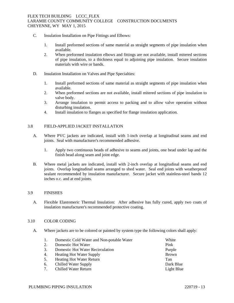
C. Insulation Installation on Pipe Fittings and Elbows:
1. Install mitered sections of pipe insulation. 2. Secure insulation materials and seal seams with manufacturer's recommended adhesive to
eliminate openings in insulation that allow passage of air to surface being insulated.
D. Insulation Installation on Valves and Pipe Specialties:
1. Install preformed valve covers manufactured of same material as pipe insulation when available.
2. When preformed valve covers are not available, install cut sections of pipe and sheet insulation to valve body. Arrange insulation to permit access to packing and to allow valve operation without disturbing insulation.
3. Install insulation to flanges as specified for flange insulation application. 4. Secure insulation to valves and specialties and seal seams with manufacturer's
recommended adhesive to eliminate openings in insulation that allow passage of air to surface being insulated.
3.7 INSTALLATION OF MINERAL-FIBER INSULATION
A. Insulation Installation on Straight Pipes and Tubes:
1. Secure each layer of preformed pipe insulation to pipe with wire or bands and tighten bands without deforming insulation materials.
2. Where vapor barriers are indicated, seal longitudinal seams, end joints, and protrusions with vapor-barrier mastic and joint sealant.
3. For insulation with factory-applied jackets on above-ambient surfaces, secure laps with outward clinched staples at 6 inches o.c.
4. For insulation with factory-applied jackets on below-ambient surfaces, do not staple longitudinal tabs. Instead, secure tabs with additional adhesive as recommended by insulation material manufacturer and seal with vapor-barrier mastic and flashing sealant.
B. Insulation Installation on Pipe Flanges:
1. Install preformed pipe insulation to outer diameter of pipe flange. 2. Make width of insulation section same as overall width of flange and bolts, plus twice the
thickness of pipe insulation. 3. Fill voids between inner circumference of flange insulation and outer circumference of
adjacent straight pipe segments with mineral-fiber blanket insulation. 4. Install jacket material with manufacturer's recommended adhesive, overlap seams at least
1 inch, and seal joints with flashing sealant.
FLEX TECH BUILDING LCCC_FLEX LARAMIE COUNTY COMMUNITY COLLEGE CONSTRUCTION DOCUMENTS CHEYENNE, WY MAY 1, 2015
PLUMBING PIPING INSULATION 220719 - 13
C. Insulation Installation on Pipe Fittings and Elbows:
1. Install preformed sections of same material as straight segments of pipe insulation when available.
2. When preformed insulation elbows and fittings are not available, install mitered sections of pipe insulation, to a thickness equal to adjoining pipe insulation. Secure insulation materials with wire or bands.
D. Insulation Installation on Valves and Pipe Specialties:
1. Install preformed sections of same material as straight segments of pipe insulation when available.
2. When preformed sections are not available, install mitered sections of pipe insulation to valve body.
3. Arrange insulation to permit access to packing and to allow valve operation without disturbing insulation.
4. Install insulation to flanges as specified for flange insulation application.
3.8 FIELD-APPLIED JACKET INSTALLATION
A. Where PVC jackets are indicated, install with 1-inch overlap at longitudinal seams and end joints. Seal with manufacturer's recommended adhesive.
1. Apply two continuous beads of adhesive to seams and joints, one bead under lap and the finish bead along seam and joint edge.
B. Where metal jackets are indicated, install with 2-inch overlap at longitudinal seams and end joints. Overlap longitudinal seams arranged to shed water. Seal end joints with weatherproof sealant recommended by insulation manufacturer. Secure jacket with stainless-steel bands 12 inches o.c. and at end joints.
3.9 FINISHES
A. Flexible Elastomeric Thermal Insulation: After adhesive has fully cured, apply two coats of insulation manufacturer's recommended protective coating.
3.10 COLOR CODING
A. Where jackets are to be colored or painted by system type the following colors shall apply:
1. Domestic Cold Water and Non-potable Water White 2. Domestic Hot Water Pink 3. Domestic Hot Water Recirculation Purple 4. Heating Hot Water Supply Brown 5. Heating Hot Water Return Tan 6. Chilled Water Supply Dark Blue 7. Chilled Water Return Light Blue

FLEX TECH BUILDING LCCC_FLEX LARAMIE COUNTY COMMUNITY COLLEGE CONSTRUCTION DOCUMENTS CHEYENNE, WY MAY 1, 2015
PLUMBING PIPING INSULATION 220719 - 14
3.11 PIPING INSULATION SCHEDULE, GENERAL
A. Acceptable preformed pipe and tubular insulation materials and thicknesses are identified for each piping system and pipe size range. If more than one material is listed for a piping system, selection from materials listed is Contractor's option.
B. Items Not Insulated: Unless otherwise indicated, do not install insulation on the following:
1. Drainage piping located in crawl spaces. 2. Underground piping 3. Chrome-plated pipes and fittings unless there is a potential for personnel injury.
3.12 INDOOR PIPING INSULATION SCHEDULE
A. All piping insulation shall comply with the type and insulation thickness noted in the schedule below and as noted elsewhere.
PIPING INSULATION SCHEDULE 1
Piping System Types
Insulation Type Fluid Tem-perature Range
< 1" 1” to 1-1/4"
1-1/2" to 3"
4" to 6"
8" and larger
Domestic Cold Water Flexible Elastomeric
or Mineral-Fiber Pre-formed Pipe Insula-tion w/Wicking Sys-tem
35 to 65 Deg F 1/2” 1/2”” 1” 1” 1”
Domestic Hot Water Domestic Hot Water Recirculation
Flexible Elastomeric or Mineral-Fiber Pre-formed Pipe Insula-tion
105 to 160 Deg F 1” 1” 1-1/2” 1-1/2” 1-1/2”
161 to 200 Deg F 1-1/2” 1-1/2” 2” 2” 2” Storm Water and Overflow
Flexible Elastomeric or Mineral-Fiber Pre-formed Pipe Insula-tion w/Wicking Sys-tem
35 to 65 Deg F 1/2” 1/2”” 1” 1” 1”
Condensate and Equipment Drain Water
Flexible Elastomeric or Mineral-Fiber Pre-formed Pipe Insula-tion
< 60 Deg F 1/2” 1” 1” 1” 1-1/2”
Notes: 1 - For piping exposed to the outside ambient conditions, increase thickness of insulation by 1/2”.
2 -
B. Roof Drain and Overflow Drain Bodies:
1. All Pipe Sizes: Insulation shall be one of the following:
FLEX TECH BUILDING LCCC_FLEX LARAMIE COUNTY COMMUNITY COLLEGE CONSTRUCTION DOCUMENTS CHEYENNE, WY MAY 1, 2015
PLUMBING PIPING INSULATION 220719 - 15
a. Flexible Elastomeric: 1 inch thick. b. Mineral-Fiber, Preformed Pipe Insulation, Type I: 1 inch thick.
C. Exposed Sanitary Drains, Domestic Water, Domestic Hot Water, and Stops for Plumbing Fixtures:
1. Provide protection shielding guard.
D. Sanitary Waste Piping Where Heat Tracing Is Installed:
1. All Pipe Sizes: Insulation shall be one of the following:
a. Mineral-Fiber, Preformed Pipe Insulation, Type I: 1-1/2 inches thick.
END OF SECTION 220719

FLEX TECH BUILDING LCCC_FLEX LARAMIE COUNTY COMMUNITY COLLEGE CONSTRUCTION DOCUMENTS CHEYENNE, WY MAY 1, 2015
DOMESTIC WATER PIPING 221116 - 1
SECTION 221116 - DOMESTIC WATER PIPING
PART 1 - GENERAL
1.1 SUMMARY
A. Section Includes:
1. Under-building-slab and aboveground domestic water pipes, tubes, and fittings inside buildings.
1.2 ACTION SUBMITTALS
A. Product Data: For transition fittings and dielectric fittings.
1.3 INFORMATIONAL SUBMITTALS
A. System purging and disinfecting activities report.
B. Field quality-control reports.
PART 2 - PRODUCTS
2.1 PIPING MATERIALS
A. Comply with requirements in "Piping Schedule" Article for applications of pipe, tube, fitting materials, and joining methods for specific services, service locations, and pipe sizes.
B. Potable-water piping and components shall comply with NSF 14 and NSF 61. Plastic piping components shall be marked with "NSF-pw."
C. All fittings shall be Lead Free (ASTM listed) and shall be made with corrosion-resistant materials. Manufacturer shall provide upon request third party certification tested in accordance with EN ISO 6509 regarding dezincification corrosion resistance and stress corrosion cracking.
2.2 COPPER TUBE AND FITTINGS
A. Hard Copper Tube: ASTM B 88, Type L water tube, drawn temper.
B. Soft Copper Tube: ASTM B 88, Type K water tube, annealed temper.
C. Wrought-Copper, Solder-Joint Fittings: ASME B16.22, wrought-copper pressure fittings.
FLEX TECH BUILDING LCCC_FLEX LARAMIE COUNTY COMMUNITY COLLEGE CONSTRUCTION DOCUMENTS CHEYENNE, WY MAY 1, 2015
DOMESTIC WATER PIPING 221116 - 2
D. Bronze Flanges: ASME B16.24, Class 150, with solder-joint ends.
E. Copper Unions:
1. MSS SP-123. 2. Cast-copper-alloy, hexagonal-stock body. 3. Ball-and-socket, metal-to-metal seating surfaces. 4. Solder-joint or threaded ends.
F. Copper Pressure-Seal-Joint Fittings:
1. Manufacturers: Subject to compliance with requirements, provide products by one of the following:
a. Elkhart Products Corporation. b. NIBCO Inc. c. Viega.
2. Fittings for NPS 2 and Smaller: Wrought-copper fitting with EPDM-rubber, O-ring seal in each end.
3. Fittings for NPS 2-1/2 to NPS 4: Cast-bronze or wrought-copper fitting with EPDM-rubber, O-ring seal in each end.
G. Copper-Tube, Extruded-Tee Connections:
1. Manufacturers: Subject to compliance with requirements, provide products by one of the following:
a. T-Drill Industries Inc.
2. Description: Tee formed in copper tube according to ASTM F 2014.
H. Appurtenances for Grooved-End Copper Tubing:
1. Manufacturers: Subject to compliance with requirements, provide products by one of the following:
a. Anvil International. b. Shurjoint Piping Products. c. Victaulic Company.
2. Bronze Fittings for Grooved-End, Copper Tubing: ASTM B 75 copper tube or ASTM B 584 bronze castings.
3. Mechanical Couplings for Grooved-End Copper Tubing:
a. Copper-tube dimensions and design similar to AWWA C606. b. Ferrous housing sections. c. EPDM-rubber gaskets suitable for hot and cold water. d. Bolts and nuts. e. Minimum Pressure Rating: 300 psig.
FLEX TECH BUILDING LCCC_FLEX LARAMIE COUNTY COMMUNITY COLLEGE CONSTRUCTION DOCUMENTS CHEYENNE, WY MAY 1, 2015
DOMESTIC WATER PIPING 221116 - 3
2.3 DUCTILE-IRON PIPE AND FITTINGS
A. Push-on-Joint, Ductile-Iron Pipe:
1. AWWA C151/A21.51. 2. Pipe shall conform to AWWA C104 when required by the water utility. 3. Push-on-joint bell and plain spigot end unless grooved or flanged ends are indicated.
B. Appurtenances for Grooved-End, Ductile-Iron Pipe:
1. Manufacturers: Subject to compliance with requirements, provide products by one of the following:
a. Shurjoint Piping Products. b. Star Pipe Products. c. Victaulic Company.
2. Fittings for Grooved-End, Ductile-Iron Pipe: ASTM A 47/A 47M, malleable-iron castings or ASTM A 536, ductile-iron castings with dimensions that match pipe.
3. Mechanical Couplings for Grooved-End, Ductile-Iron-Piping:
a. AWWA C606 for ductile-iron-pipe dimensions. b. Ferrous housing sections. c. EPDM-rubber gaskets suitable for hot and cold water. d. Bolts and nuts. e. Minimum Pressure Rating:
1) NPS 4 to NPS 18: 250 psig.
f. AWWA C606 for stainless-steel-pipe dimensions. g. Stainless-steel housing sections. h. Stainless-steel bolts and nuts.
2.4 PIPING JOINING MATERIALS
A. Pipe-Flange Gasket Materials:
1. AWWA C110/A21.10, rubber, flat face, 1/8 inch thick or ASME B16.21, nonmetallic and asbestos free unless otherwise indicated.
2. Full-face or ring type unless otherwise indicated.
B. Metal, Pipe-Flange Bolts and Nuts: ASME B18.2.1, carbon steel unless otherwise indicated.
C. Solder Filler Metals: ASTM B 32, lead-free alloys.
D. Flux: ASTM B 813, water flushable.
E. Brazing Filler Metals: AWS A5.8/A5.8M, BCuP Series, copper-phosphorus alloys for general-duty brazing unless otherwise indicated.
FLEX TECH BUILDING LCCC_FLEX LARAMIE COUNTY COMMUNITY COLLEGE CONSTRUCTION DOCUMENTS CHEYENNE, WY MAY 1, 2015
DOMESTIC WATER PIPING 221116 - 4
2.5 TRANSITION FITTINGS
A. General Requirements:
1. Same size as pipes to be joined. 2. Pressure rating at least equal to pipes to be joined. 3. End connections compatible with pipes to be joined.
2.6 DIELECTRIC FITTINGS
A. General Requirements: Assembly of copper alloy and ferrous materials with separating nonconductive insulating material. Include end connections compatible with pipes to be joined.
B. Dielectric Unions:
1. Manufacturers: Subject to compliance with requirements, available manufacturers offering products that may be incorporated into the Work include, but are not limited to, the following:
a. Capitol Manufacturing Company; member of the Phoenix Forge Group. b. Central Plastics Company. c. Hart Industries International, Inc. d. Jomar International. e. Matco-Norca. f. McDonald, A. Y. Mfg. Co. g. Watts; a division of Watts Water Technologies, Inc. h. Wilkins; a Zurn company.
2. Standard: ASSE 1079. 3. Pressure Rating: 250 psig 4. End Connections: Solder-joint copper alloy and threaded ferrous.
C. Dielectric Nipples and Couplings:
1. Manufacturers: Subject to compliance with requirements, provide products by one of the following:
a. Elster Perfection Corporation. b. Grinnell Mechanical Products; Tyco Fire Products LP. c. Matco-Norca. d. Precision Plumbing Products, Inc. e. Victaulic Company.
2. Standard: IAPMO PS 66. 3. Electroplated steel nipple complying with ASTM F 1545. 4. Pressure Rating and Temperature: 300 psig at 225 deg F. 5. End Connections: Male threaded or grooved. 6. Lining: Inert and noncorrosive, propylene.

FLEX TECH BUILDING LCCC_FLEX LARAMIE COUNTY COMMUNITY COLLEGE CONSTRUCTION DOCUMENTS CHEYENNE, WY MAY 1, 2015
DOMESTIC WATER PIPING 221116 - 5
PART 3 - EXECUTION
3.1 EARTHWORK
A. Comply with requirements in Section 312000 "Earth Moving" for excavating, trenching, and backfilling.
3.2 PIPING INSTALLATION
A. Drawing plans, schematics, and diagrams indicate general location and arrangement of domestic water piping. Indicated locations and arrangements are used to size pipe and calculate friction loss, expansion, and other design considerations. Install piping as indicated unless deviations to layout are approved on coordination drawings.
B. Install copper tubing under building slab according to CDA's "Copper Tube Handbook."
C. Install ductile-iron piping under building slab with restrained joints according to AWWA C600 and AWWA M41.
D. Install shutoff valve, hose-end drain valve, strainer, pressure gage, and test tee with valve inside the building at each domestic water-service entrance. Comply with requirements for pressure gages in Section 220519 "Meters and Gages for Plumbing Piping" and with requirements for drain valves and strainers in Section 221119 "Domestic Water Piping Specialties."
E. Install domestic water piping level without pitch and plumb.
F. Rough-in domestic water piping for water-meter installation according to utility company's requirements.
G. Install piping indicated to be exposed and piping in equipment rooms and service areas at right angles or parallel to building walls. Diagonal runs are prohibited unless specifically indicated otherwise.
H. Install piping above accessible ceilings to allow sufficient space for ceiling panel removal, and coordinate with other services occupying that space.
I. Install piping to permit valve servicing.
J. Install nipples, unions, special fittings, and valves with pressure ratings the same as or higher than the system pressure rating used in applications below unless otherwise indicated.
K. Install piping free of sags and bends.
L. Install fittings for changes in direction and branch connections.
M. Install unions in copper tubing at final connection to each piece of equipment, machine, and specialty.
FLEX TECH BUILDING LCCC_FLEX LARAMIE COUNTY COMMUNITY COLLEGE CONSTRUCTION DOCUMENTS CHEYENNE, WY MAY 1, 2015
DOMESTIC WATER PIPING 221116 - 6
N. Install pressure gages on suction and discharge piping for each plumbing pump and packaged booster pump. Comply with requirements for pressure gages in Section 220519 "Meters and Gages for Plumbing Piping."
O. Install thermometers on inlet and outlet piping from each water heater. Comply with requirements for thermometers in Section 220519 "Meters and Gages for Plumbing Piping."
P. Install sleeves for piping penetrations of walls, ceilings, and floors. Comply with requirements for sleeves specified in Section 220517 "Sleeves and Sleeve Seals for Plumbing Piping."
Q. Install sleeve seals for piping penetrations of concrete walls and slabs. Comply with requirements for sleeve seals specified in Section 220517 "Sleeves and Sleeve Seals for Plumbing Piping."
R. Install escutcheons for piping penetrations of walls, ceilings, and floors. Comply with requirements for escutcheons specified in Section 220518 "Escutcheons for Plumbing Piping."
3.3 JOINT CONSTRUCTION
A. Ream ends of pipes and tubes and remove burrs. Bevel plain ends of steel pipe.
B. Remove scale, slag, dirt, and debris from inside and outside of pipes, tubes, and fittings before assembly.
C. Threaded Joints: Thread pipe with tapered pipe threads according to ASME B1.20.1. Cut threads full and clean using sharp dies. Ream threaded pipe ends to remove burrs and restore full ID. Join pipe fittings and valves as follows:
1. Apply appropriate tape or thread compound to external pipe threads. 2. Damaged Threads: Do not use pipe or pipe fittings with threads that are corroded or
damaged.
D. Brazed Joints for Copper Tubing: Comply with CDA's "Copper Tube Handbook," "Brazed Joints" chapter.
E. Soldered Joints for Copper Tubing: Apply ASTM B 813, water-flushable flux to end of tube. Join copper tube and fittings according to ASTM B 828 or CDA's "Copper Tube Handbook."
F. Pressure-Sealed Joints for Copper Tubing: Join copper tube and pressure-seal fittings with tools recommended by fitting manufacturer.
G. Extruded-Tee Connections: Form tee in copper tube according to ASTM F 2014. Use tool designed for copper tube; drill pilot hole, form collar for outlet, dimple tube to form seating stop, and braze branch tube into collar.
H. Joint Construction for Grooved-End Copper Tubing: Make joints according to AWWA C606. Roll groove ends of tubes. Lubricate and install gasket over ends of tubes or tube and fitting. Install coupling housing sections over gasket with keys seated in tubing grooves. Install and tighten housing bolts.

FLEX TECH BUILDING LCCC_FLEX LARAMIE COUNTY COMMUNITY COLLEGE CONSTRUCTION DOCUMENTS CHEYENNE, WY MAY 1, 2015
DOMESTIC WATER PIPING 221116 - 7
I. Joint Construction for Grooved-End, Ductile-Iron Piping: Make joints according to AWWA C606. Cut round-bottom grooves in ends of pipe at gasket-seat dimension required for specified (flexible or rigid) joint. Lubricate and install gasket over ends of pipes or pipe and fitting. Install coupling housing sections over gasket with keys seated in piping grooves. Install and tighten housing bolts.
J. Flanged Joints: Select appropriate asbestos-free, nonmetallic gasket material in size, type, and thickness suitable for domestic water service. Join flanges with gasket and bolts according to ASME B31.9.
K. Joints for Dissimilar-Material Piping: Make joints using adapters compatible with materials of both piping systems.
3.4 TRANSITION FITTING INSTALLATION
A. Install transition couplings at joints of dissimilar piping.
3.5 DIELECTRIC FITTING INSTALLATION
A. Install dielectric fittings in piping at connections of dissimilar metal piping and tubing.
B. Dielectric Fittings for NPS 2 and Smaller: Use dielectric couplings or nipples.
C. Dielectric Fittings for NPS 2-1/2 to NPS 4: Use dielectric nipples.
3.6 HANGER AND SUPPORT INSTALLATION
A. Comply with requirements for pipe hanger, support products, and installation in Section 220529 "Hangers and Supports for Plumbing Piping and Equipment."
1. Vertical Piping: MSS Type 8 or 42, clamps. 2. Individual, Straight, Horizontal Piping Runs:
a. 100 feet and less: MSS Type 1, adjustable, steel clevis hangers. b. Longer Than 100 feet: MSS Type 43, adjustable roller hangers. c. Longer Than 100 feet if indicated: MSS Type 49, spring cushion rolls.
3. Multiple, Straight, Horizontal Piping Runs 100 feet or longer: MSS Type 44, pipe rolls. Support pipe rolls on trapeze.
4. Base of Vertical Piping: MSS Type 52, spring hangers.
B. Support vertical piping and tubing at base and at each floor.
C. Rod diameter may be reduced one size for double-rod hangers, to a minimum of 3/8 inch.
D. Install hangers for copper tubing with the following maximum horizontal spacing and minimum rod diameters:

FLEX TECH BUILDING LCCC_FLEX LARAMIE COUNTY COMMUNITY COLLEGE CONSTRUCTION DOCUMENTS CHEYENNE, WY MAY 1, 2015
DOMESTIC WATER PIPING 221116 - 8
1. NPS 3/4 and Smaller: 60 inches with 3/8-inch rod. 2. NPS 1 and NPS 1-1/4: 72 inches with 3/8-inch rod. 3. NPS 1-1/2 and NPS 2: 96 inches with 3/8-inch rod. 4. NPS 2-1/2: 108 inches with 1/2-inch rod. 5. NPS 3 to NPS 5: 10 feet with 1/2-inch rod.
E. Install supports for vertical copper tubing every 10 feet.
F. Support piping and tubing not listed in this article according to MSS SP-69 and manufacturer's written instructions.
3.7 CONNECTIONS
A. Drawings indicate general arrangement of piping, fittings, and specialties.
B. When installing piping adjacent to equipment and machines, allow space for service and maintenance.
C. Connect domestic water piping to exterior water-service piping. Use transition fitting to join dissimilar piping materials.
D. Connect domestic water piping to water-service piping with shutoff valve; extend and connect to the following:
1. Water Heaters: Cold-water inlet and hot-water outlet piping in sizes indicated, but not smaller than sizes of water heater connections.
2. Plumbing Fixtures: Cold- and hot-water-supply piping in sizes indicated, but not smaller than that required by plumbing code.
3. Equipment: Cold- and hot-water-supply piping as indicated, but not smaller than equipment connections. Provide shutoff valve and union for each connection. Use flanges instead of unions for NPS 2-1/2 and larger.
E. Water Utility Connection: Comply with the utility company’s requirements. Where differences occur between these specifications and the utility company’s requirements, comply with the utility company’s requirements to allow for their approval. Notify Project Manager of any and all changes for Engineer’s review.
3.8 IDENTIFICATION
A. Identify system components. Comply with requirements for identification materials and installation in Section 220553 "Identification for Plumbing Piping and Equipment."
B. Label pressure piping with system operating pressure.
3.9 FIELD QUALITY CONTROL
A. Perform the following tests and inspections:
FLEX TECH BUILDING LCCC_FLEX LARAMIE COUNTY COMMUNITY COLLEGE CONSTRUCTION DOCUMENTS CHEYENNE, WY MAY 1, 2015
DOMESTIC WATER PIPING 221116 - 9
1. Piping Inspections:
a. Do not enclose, cover, or put piping into operation until it has been inspected and approved by authorities having jurisdiction.
b. During installation, notify authorities having jurisdiction at least one day before inspection must be made. Perform tests specified below in presence of authorities having jurisdiction:
1) Roughing-in Inspection: Arrange for inspection of piping before concealing or closing in after roughing in and before setting fixtures.
2) Final Inspection: Arrange for authorities having jurisdiction to observe tests specified in "Piping Tests" Subparagraph below and to ensure compliance with requirements.
c. Reinspection: If authorities having jurisdiction find that piping will not pass tests or inspections, make required corrections and arrange for reinspection.
d. Reports: Prepare inspection reports and have them signed by authorities having jurisdiction.
2. Piping Tests:
a. Fill domestic water piping. Check components to determine that they are not air bound and that piping is full of water.
b. Test for leaks and defects in new piping and parts of existing piping that have been altered, extended, or repaired. If testing is performed in segments, submit a separate report for each test, complete with diagram of portion of piping tested.
c. Leave new, altered, extended, or replaced domestic water piping uncovered and unconcealed until it has been tested and approved. Expose work that was covered or concealed before it was tested.
d. Cap and subject piping to static water pressure of 50 psig above operating pressure, without exceeding pressure rating of piping system materials. Isolate test source and allow it to stand for four hours. Leaks and loss in test pressure constitute defects that must be repaired.
e. Repair leaks and defects with new materials, and retest piping or portion thereof until satisfactory results are obtained.
f. Prepare reports for tests and for corrective action required.
B. Domestic water piping will be considered defective if it does not pass tests and inspections.
C. Prepare test and inspection reports.
3.10 ADJUSTING
A. Perform the following adjustments before operation:
1. Close drain valves, hydrants, and hose bibbs. 2. Open shutoff valves to fully open position. 3. Open throttling valves to proper setting. 4. Adjust balancing valves in hot-water-circulation return piping to provide adequate flow.
FLEX TECH BUILDING LCCC_FLEX LARAMIE COUNTY COMMUNITY COLLEGE CONSTRUCTION DOCUMENTS CHEYENNE, WY MAY 1, 2015
DOMESTIC WATER PIPING 221116 - 10
a. Manually adjust ball-type balancing valves in hot-water-circulation return piping to provide hot-water flow in each branch.
b. Adjust calibrated balancing valves to flows indicated.
5. Remove plugs used during testing of piping and for temporary sealing of piping during installation.
6. Remove and clean strainer screens. Close drain valves and replace drain plugs. 7. Remove filter cartridges from housings and verify that cartridges are as specified for
application where used and are clean and ready for use. 8. Check plumbing specialties and verify proper settings, adjustments, and operation.
3.11 CLEANING
A. Clean and disinfect potable domestic water piping as follows:
1. Purge new piping and parts of existing piping that have been altered, extended, or repaired before using.
2. Use purging and disinfecting procedures prescribed by authorities having jurisdiction; if methods are not prescribed, use procedures described in either AWWA C651 or AWWA C652 or follow procedures described below:
a. Flush piping system with clean, potable water until dirty water does not appear at outlets.
b. Fill and isolate system according to either of the following:
1) Fill system or part thereof with water/chlorine solution with at least 50 ppm of chlorine. Isolate with valves and allow to stand for 24 hours.
2) Fill system or part thereof with water/chlorine solution with at least 200 ppm of chlorine. Isolate and allow to stand for three hours.
c. Flush system with clean, potable water until no chlorine is in water coming from system after the standing time.
d. Repeat procedures if biological examination shows contamination. e. Submit water samples in sterile bottles to authorities having jurisdiction.
3.12 PIPING SCHEDULE
A. Transition and special fittings with pressure ratings at least equal to piping rating may be used in applications below unless otherwise indicated.
B. Flanges and unions may be used for aboveground piping joints unless otherwise indicated.
C. Fitting Option: Extruded-tee connections and brazed joints may be used on aboveground copper tubing.
D. Under-building-slab, domestic water, building-service piping, NPS 21/2” and smaller, shall be one of the following unless specifically indicated otherwise by the water utility:

FLEX TECH BUILDING LCCC_FLEX LARAMIE COUNTY COMMUNITY COLLEGE CONSTRUCTION DOCUMENTS CHEYENNE, WY MAY 1, 2015
DOMESTIC WATER PIPING 221116 - 11
1. Soft copper tube, ASTM B 88, Type K; wrought-copper, solder-joint fittings; and brazed joints.
E. Under-building-slab, domestic water piping, NPS 2 and smaller, shall be one of the following:
1. Hard or soft copper tube, ASTM B 88, Type K; wrought-copper, solder-joint fittings; and brazed joints.
F. Aboveground domestic water piping, NPS 2 and smaller, shall be one of the following:
1. Hard copper tube, ASTM B 88, Type L; wrought-copper, solder-joint fittings; and soldered joints.
2. Hard copper tube, ASTM B 88, Type L; copper pressure-seal-joint fittings; and pressure-sealed joints.
G. Aboveground domestic water piping, NPS 2-1/2 to NPS 4, shall be one of the following:
1. Hard copper tube, ASTM B 88, Type L ; wrought-copper, solder-joint fittings; and brazed joints.
2. Hard copper tube, ASTM B 88, Type L; copper pressure-seal-joint fittings; and pressure-sealed joints.
3. Hard copper tube, ASTM B 88, Type L; grooved-joint, copper-tube appurtenances; and grooved joints.
3.13 VALVE SCHEDULE
A. Drawings indicate valve types to be used. Where specific valve types are not indicated, the following requirements apply:
1. Shutoff Duty: Use ball valves for piping NPS 2 and smaller. Use butterfly or ball valves with flanged ends for piping NPS 2-1/2 and larger.
2. Throttling Duty: Use ball valves for piping NPS 2 and smaller. Use butterfly or ball valves with flanged ends for piping NPS 2-1/2 and larger.
3. Hot-Water Circulation Piping, Balancing Duty: Calibrated balancing valves. 4. Drain Duty: Hose-end drain valves.
B. Use check valves to maintain correct direction of domestic water flow to and from equipment.
C. Iron grooved-end valves may be used with grooved-end piping.
END OF SECTION 221116