flexible, heat-resistant, and flame-retardant glass fiber
TRANSCRIPT
energies
Article
Flexible, Heat-Resistant, and Flame-Retardant GlassFiber Nonwoven/Glass Platelet Composite Separatorfor Lithium-Ion Batteries
Ulrich Schadeck 1,*, Kanat Kyrgyzbaev 1, Heiko Zettl 2, Thorsten Gerdes 1 and Ralf Moos 3
1 Department of Materials Processing, University of Bayreuth, 95440 Bayreuth, Germany;[email protected] (K.K.); [email protected] (T.G.)
2 Vitrulan Textile Glass GmbH, 95509 Marktschorgast, Germany; [email protected] Department of Functional Materials, Zentrum für Energietechnik (ZET), University of Bayreuth,
95440 Bayreuth, Germany; [email protected]* Correspondence: [email protected]; Tel.: +49-921-557-216
Received: 26 March 2018; Accepted: 13 April 2018; Published: 20 April 2018�����������������
Abstract: A new type of high-temperature stable and self-supporting composite separator forlithium-ion batteries was developed consisting of custom-made ultrathin micrometer-sized glassplatelets embedded in a glass fiber nonwoven together with a water-based sodium alginate binder.The physical and electrochemical properties were investigated and compared to commercialpolymer-based separators. Full-cell configuration cycling tests at different current rates wereperformed using graphite and lithium iron phosphate as electrode materials. The glass separator washigh-temperature tested and showed a stability up to at least 600 ◦C without significant shrinking.Furthermore, it showed an exceptional wettability for non-aqueous electrolytes. The electrochemicalperformance was excellent compared to commercially available polymer-based separators. The resultsclearly show that glass platelets integrated into a glass fiber nonwoven performs remarkably well asa separator material in lithium-ion batteries and show high-temperature stability.
Keywords: glass platelets; composite separator; high-temperature stability; full-cell configurationcycling tests; lithium-ion battery
1. Introduction
Lithium-ion batteries (LIBs) are widely used for consumer electronics and are promising powersources for electric vehicles (EVs) or hybrid electric vehicles (HEVs) due to their high energy densityand efficient cycling stability compared to other battery types [1–5].
The separator is crucial for the safety of a LIB since it physically separates the battery electrodesand prevents internal short circuits. As the cell temperature can rise to critical temperatures, whetherin the case of charging at high current rates or in abnormal conditions such as unfortunate overchargeor cell damage, the separator must remain mechanically and chemically stable in order to reducethe risk of serious damage [6,7]. Recent cases of catastrophic battery failures in smartphones wereattributed, among other things, to the failure of the separator, which consists of an ultrathin (approx.4.5 to 5 µm), low-temperature stable polymer membrane with a 1 to 2 µm ceramic coating on oneside [8]. Besides its desirable stability at high temperatures, a separator should be well wettable withnon-aqueous electrolytes and needs a porous structure for a preferably unimpeded flow of ions toenable fast charging/discharging of a LIB [9,10].
Microporous polyolefin-based membranes consisting of polyethylene (PE) or polypropylene (PP)used to be the standard choice as separators for LIBs. They are easy to process and show decentmechanical and chemical stabilities at an acceptable cost [4]. On the other hand, the poor stability
Energies 2018, 11, 999; doi:10.3390/en11040999 www.mdpi.com/journal/energies
Energies 2018, 11, 999 2 of 14
at high temperatures and the concomitant effect of shrinking, as well as high specific resistances,are prohibitive for their use in high-power applications such as for EVs or for HEV [11,12].
To improve polyolefin-based separators toward high-temperature stability, they are eithercoated with inorganic micrometer-sized particles or with more temperature-stable polymers [13].These composite separators show improved stability to high temperatures, wettability withnon-aqueous electrolytes, and electrochemical performance in a LIB [14–16]. Porous membranesmade with more thermally stable polymers, such as polyacrylonitrile (PAN), polyimide (PI),or melamine-resin, mostly in the shape of nanofibers, show reduced shrinking at temperaturesup to 300 ◦C and good battery performance [17–30]. Nevertheless, the thermal stability is stilllimited to the melting points of the used polymers or even lower if a polymer tends to shrink.Therefore, high-temperature-stable, non-shrinking materials such as glass or ceramics could be usedfor separators [12].
As ceramic particles are mostly applied in combination with different polymers, glass is hardlyused as a material for separators for organic solvent-based LIBs. However, some promising results havebeen reported with preparations of glass- or ceramic-based membranes with either glass or ceramicparticles or glass fibers with no polymers, with the exception of the binder, respectively [31–33].
Up to now, glass in the shape of micrometer-sized platelets has not been an object of research forseparators for LIBs. Today, glass platelets are used in polymer matrices to improve either the mechanicalproperties and/or the chemical stability [34]. In addition, metal oxide-coated glass platelets are used aspigment additives for paintings and cosmetics [35]. Glass fibers serve, e.g., as the basis for reinforcementsfor automotive applications, for thermal insulation purposes, and for wallpapers [36–38]. Additionally,applications as separators for lead-acid batteries have been reported [39] and studies regarding theirpotential as candidates for separators for Li-S batteries have shown promising results [40].
In this work, a high-temperature-stable, self-supporting, and flexible composite separatorfor liquid electrolyte lithium-ion batteries that consist of a glass fiber nonwoven with integratedcustom-made micrometer-sized glass platelets is presented. It is a continuation of our previousstudy [41], in which the electrochemical properties of single porous and non-porous glass platelets asseparators have been studied. In the present study, important properties for self-supporting batteryseparators such as the tensile strength, the wettability, the electrolyte uptake, and the thermal stability,as well as the electrochemical behavior in graphite/lithium iron phosphate full-cells are studied,mostly compared to commercially available polymer-based separators.
2. Results
2.1. Physical Properties
2.1.1. Morphology
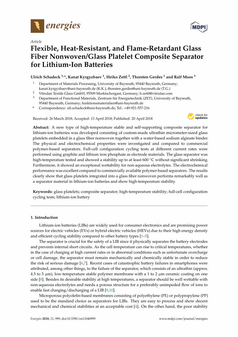
The scanning electron micrographs of the starting materials for the glass composite separator areshown in Figure 1.
The glass platelets showed a flat surface and in the case of ground glass platelets, an average particlesize below 32 µm (d50 = 23.1 µm) and a thickness that was determined to an average value below 5 µm.The resulting aspect ratio was 1:6 to 1:10. In this study, the glass platelets were ground in a jet mill.The glass fiber nonwoven showed strait glass fibers with an average length of 12 mm and diameterof 10 µm. The scanning electron microscopy (SEM) images show residues of the binder, a modifiedpolycarboxylic acid (detailed view in Figure 1b). According to the nonwoven manufacturer’s data sheet,the thickness of the glass fiber nonwoven was 300 µm. The measured thickness of 188 µm was less thanthe stated value due to interlacing of the fibers during measuring.
Energies 2018, 11, 999 3 of 14Energies 2018, 11, x FOR PEER REVIEW 3 of 14
(a)
(b)
Figure 1. Scanning electron microscopy (SEM) images of the starting materials of a glass composite separator, (a) non-ground glass platelets, (b) glass fiber nonwoven (Johns Manville, Denver, CO, USA) with binder residues between single glass fibers from the nonwoven manufacturing process (detailed view).
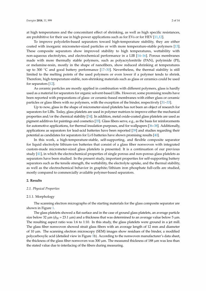
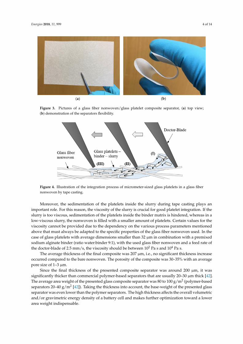
The composite separator was manufactured by a tape casting process (see Section 3.2). After the process, the glass platelets were well aligned in the glass composite separator in a horizontal direction, embedded in the glass fiber nonwoven as can be seen from the top view (Figure 2a) and the bottom view (Figure 2b). Figure 3a,b shows the appearance of the separator and a demonstration of its flexibility. A satisfying integration process of the glass platelets into the glass fiber nonwoven with just one tape-casting step is influenced by three major criteria: the viscosity of the platelet-binder slurry; the platelet dimensions, e.g., the average edge length; and the specific size of the fiber interspaces in the glass fiber nonwoven. When the average platelet dimensions are bigger than the average sizes of the interspaces between the glass fibers, an integration of the platelets from top to bottom is hindered. Binder residues, as marked in Figure 2b, are another hindering factor in the integration process. Therefore, smaller glass platelets can penetrate the glass fiber network more easily. An illustration of the platelet integration process is shown in Figure 4. The integration process can be divided into three parts. First, the glass platelets do not have any specific alignment in the platelet-binder slurry (I). Then, through the influence of the moving and angled doctor-blade, the platelets are mostly aligned in a horizontal direction (II) and then pushed inside the glass fiber nonwoven (III).
(a)
(b)
Figure 1. Scanning electron microscopy (SEM) images of the starting materials of a glass compositeseparator, (a) non-ground glass platelets, (b) glass fiber nonwoven (Johns Manville, Denver, CO, USA) withbinder residues between single glass fibers from the nonwoven manufacturing process (detailed view).
The composite separator was manufactured by a tape casting process (see Section 3.2). After theprocess, the glass platelets were well aligned in the glass composite separator in a horizontal direction,embedded in the glass fiber nonwoven as can be seen from the top view (Figure 2a) and the bottomview (Figure 2b). Figure 3a,b shows the appearance of the separator and a demonstration of itsflexibility. A satisfying integration process of the glass platelets into the glass fiber nonwoven with justone tape-casting step is influenced by three major criteria: the viscosity of the platelet-binder slurry;the platelet dimensions, e.g., the average edge length; and the specific size of the fiber interspaces inthe glass fiber nonwoven. When the average platelet dimensions are bigger than the average sizes ofthe interspaces between the glass fibers, an integration of the platelets from top to bottom is hindered.Binder residues, as marked in Figure 2b, are another hindering factor in the integration process.Therefore, smaller glass platelets can penetrate the glass fiber network more easily. An illustrationof the platelet integration process is shown in Figure 4. The integration process can be divided intothree parts. First, the glass platelets do not have any specific alignment in the platelet-binder slurry (I).Then, through the influence of the moving and angled doctor-blade, the platelets are mostly aligned ina horizontal direction (II) and then pushed inside the glass fiber nonwoven (III).
Energies 2018, 11, x FOR PEER REVIEW 3 of 14
(a)
(b)
Figure 1. Scanning electron microscopy (SEM) images of the starting materials of a glass composite separator, (a) non-ground glass platelets, (b) glass fiber nonwoven (Johns Manville, Denver, CO, USA) with binder residues between single glass fibers from the nonwoven manufacturing process (detailed view).
The composite separator was manufactured by a tape casting process (see Section 3.2). After the process, the glass platelets were well aligned in the glass composite separator in a horizontal direction, embedded in the glass fiber nonwoven as can be seen from the top view (Figure 2a) and the bottom view (Figure 2b). Figure 3a,b shows the appearance of the separator and a demonstration of its flexibility. A satisfying integration process of the glass platelets into the glass fiber nonwoven with just one tape-casting step is influenced by three major criteria: the viscosity of the platelet-binder slurry; the platelet dimensions, e.g., the average edge length; and the specific size of the fiber interspaces in the glass fiber nonwoven. When the average platelet dimensions are bigger than the average sizes of the interspaces between the glass fibers, an integration of the platelets from top to bottom is hindered. Binder residues, as marked in Figure 2b, are another hindering factor in the integration process. Therefore, smaller glass platelets can penetrate the glass fiber network more easily. An illustration of the platelet integration process is shown in Figure 4. The integration process can be divided into three parts. First, the glass platelets do not have any specific alignment in the platelet-binder slurry (I). Then, through the influence of the moving and angled doctor-blade, the platelets are mostly aligned in a horizontal direction (II) and then pushed inside the glass fiber nonwoven (III).
(a)
(b)
Figure 2. Scanning electron microscopy (SEM) images of a glass fiber nonwoven/glass plateletcomposite separator, (a) top view; (b) bottom view.
Energies 2018, 11, 999 4 of 14
Energies 2018, 11, x FOR PEER REVIEW 4 of 14
Figure 2. Scanning electron microscopy (SEM) images of a glass fiber nonwoven/glass platelet composite separator, (a) top view; (b) bottom view.
(a)
(b)
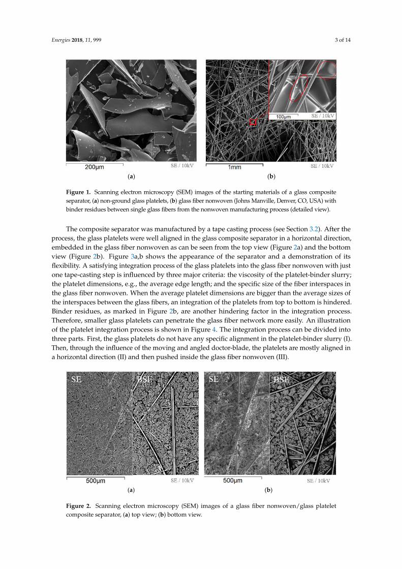
Figure 3. Pictures of a glass fiber nonwoven/glass platelet composite separator, (a) top view; (b) demonstration of the separators flexibility.
Figure 4. Illustration of the integration process of micrometer-sized glass platelets in a glass fiber nonwoven by tape casting.
Moreover, the sedimentation of the platelets inside the slurry during tape casting plays an important role. For this reason, the viscosity of the slurry is crucial for good platelet integration. If the slurry is too viscous, sedimentation of the platelets inside the binder matrix is hindered, whereas in a low-viscous slurry, the nonwoven is filled with a smaller amount of platelets. Certain values for the viscosity cannot be provided due to the dependency on the various process parameters mentioned above that must always be adapted to the specific properties of the glass fiber nonwoven used. In the case of glass platelets with average dimensions smaller than 32 µm in combination with a premixed sodium alginate binder (ratio water:binder 9:1), with the used glass fiber nonwoven and a feed rate of the doctor-blade of 2.5 mm/s, the viscosity should be between 102 Pa s and 104 Pa s.
The average thickness of the final composite was 207 µm, i.e., no significant thickness increase occurred compared to the bare nonwoven. The porosity of the composite was 30–35% with an average pore size of 1–3 µm.
Since the final thickness of the presented composite separator was around 200 µm, it was significantly thicker than commercial polymer-based separators that are usually 20–30 µm thick [42]. The average area weight of the presented glass composite separator was 80 to 100 g/m2 (polymer-based separators 20–40 g/m2 [42]). Taking the thickness into account, the base-weight of the presented glass separator was even lower than the polymer separators. The high thickness affects the overall volumetric and/or gravimetric energy density of a battery cell and makes further optimization toward a lower area weight indispensable.
Figure 3. Pictures of a glass fiber nonwoven/glass platelet composite separator, (a) top view;(b) demonstration of the separators flexibility.
Energies 2018, 11, x FOR PEER REVIEW 4 of 14
Figure 2. Scanning electron microscopy (SEM) images of a glass fiber nonwoven/glass platelet composite separator, (a) top view; (b) bottom view.
(a)
(b)
Figure 3. Pictures of a glass fiber nonwoven/glass platelet composite separator, (a) top view; (b) demonstration of the separators flexibility.
Figure 4. Illustration of the integration process of micrometer-sized glass platelets in a glass fiber nonwoven by tape casting.
Moreover, the sedimentation of the platelets inside the slurry during tape casting plays an important role. For this reason, the viscosity of the slurry is crucial for good platelet integration. If the slurry is too viscous, sedimentation of the platelets inside the binder matrix is hindered, whereas in a low-viscous slurry, the nonwoven is filled with a smaller amount of platelets. Certain values for the viscosity cannot be provided due to the dependency on the various process parameters mentioned above that must always be adapted to the specific properties of the glass fiber nonwoven used. In the case of glass platelets with average dimensions smaller than 32 µm in combination with a premixed sodium alginate binder (ratio water:binder 9:1), with the used glass fiber nonwoven and a feed rate of the doctor-blade of 2.5 mm/s, the viscosity should be between 102 Pa s and 104 Pa s.
The average thickness of the final composite was 207 µm, i.e., no significant thickness increase occurred compared to the bare nonwoven. The porosity of the composite was 30–35% with an average pore size of 1–3 µm.
Since the final thickness of the presented composite separator was around 200 µm, it was significantly thicker than commercial polymer-based separators that are usually 20–30 µm thick [42]. The average area weight of the presented glass composite separator was 80 to 100 g/m2 (polymer-based separators 20–40 g/m2 [42]). Taking the thickness into account, the base-weight of the presented glass separator was even lower than the polymer separators. The high thickness affects the overall volumetric and/or gravimetric energy density of a battery cell and makes further optimization toward a lower area weight indispensable.
Figure 4. Illustration of the integration process of micrometer-sized glass platelets in a glass fibernonwoven by tape casting.
Moreover, the sedimentation of the platelets inside the slurry during tape casting plays animportant role. For this reason, the viscosity of the slurry is crucial for good platelet integration. If theslurry is too viscous, sedimentation of the platelets inside the binder matrix is hindered, whereas in alow-viscous slurry, the nonwoven is filled with a smaller amount of platelets. Certain values for theviscosity cannot be provided due to the dependency on the various process parameters mentionedabove that must always be adapted to the specific properties of the glass fiber nonwoven used. In thecase of glass platelets with average dimensions smaller than 32 µm in combination with a premixedsodium alginate binder (ratio water:binder 9:1), with the used glass fiber nonwoven and a feed rate ofthe doctor-blade of 2.5 mm/s, the viscosity should be between 102 Pa s and 104 Pa s.
The average thickness of the final composite was 207 µm, i.e., no significant thickness increaseoccurred compared to the bare nonwoven. The porosity of the composite was 30–35% with an averagepore size of 1–3 µm.
Since the final thickness of the presented composite separator was around 200 µm, it wassignificantly thicker than commercial polymer-based separators that are usually 20–30 µm thick [42].The average area weight of the presented glass composite separator was 80 to 100 g/m2 (polymer-basedseparators 20–40 g/m2 [42]). Taking the thickness into account, the base-weight of the presented glassseparator was even lower than the polymer separators. The high thickness affects the overall volumetricand/or gravimetric energy density of a battery cell and makes further optimization toward a lowerarea weight indispensable.
Energies 2018, 11, 999 5 of 14
2.1.2. Thermal Stability
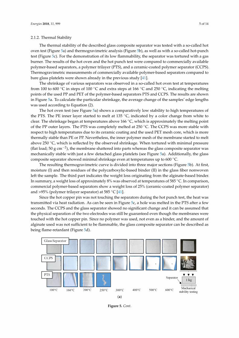
The thermal stability of the described glass composite separator was tested with a so-called hotoven test (Figure 5a) and thermogravimetric analysis (Figure 5b), as well as with a so-called hot-punchtest (Figure 5c). For the demonstration of its low flammability, the separator was tortured with a gasburner. The results of the hot oven and the hot punch test were compared to commercially availablepolymer-based separators, a polymer trilayer (PTS), and a ceramic-coated polymer separator (CCPS).Thermogravimetric measurements of commercially available polymer-based separators compared tobare glass platelets were shown already in the previous study [41].
The shrinkage of various separators was observed in a so-called hot oven test at temperaturesfrom 100 to 600 ◦C in steps of 100 ◦C and extra steps at 166 ◦C and 250 ◦C, indicating the meltingpoints of the used PP and PET of the polymer-based separators PTS and CCPS. The results are shownin Figure 5a. To calculate the particular shrinkage, the average change of the samples’ edge lengthswas used according to Equation (2).
The hot oven test (see Figure 5a) shows a comparatively low stability to high temperatures ofthe PTS. The PE inner layer started to melt at 135 ◦C, indicated by a color change from white toclear. The shrinkage began at temperatures above 166 ◦C, which is approximately the melting pointof the PP outer layers. The PTS was completely melted at 250 ◦C. The CCPS was more stable withrespect to high temperatures due to its ceramic coating and the used PET mesh core, which is morethermally stable than PE or PP. Nevertheless, the inner polymer mesh of the membrane started to meltabove 250 ◦C, which is reflected by the observed shrinkage. When tortured with minimal pressure(flat load; 50 g cm−2), the membrane shattered into parts whereas the glass composite separator wasmechanically stable with just a few detached glass platelets (see Figure 5a). Additionally, the glasscomposite separator showed minimal shrinkage even at temperatures up to 600 ◦C.
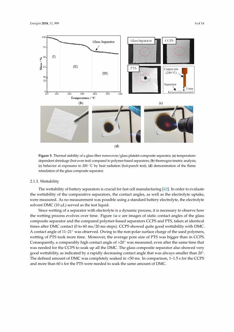
The resulting thermogravimetric curve is divided into three major sections (Figure 5b). At first,moisture (I) and then residues of the polycarboxylic-based binder (II) in the glass fiber nonwovenleft the sample. The third part indicates the weight loss originating from the alginate-based binder.In summary, a weight loss of approximately 8% was observed at temperatures of 585 ◦C. In comparison,commercial polymer-based separators show a weight loss of 25% (ceramic-coated polymer separator)and >95% (polymer trilayer separator) at 585 ◦C [41].
Since the hot copper pin was not touching the separators during the hot punch test, the heat wastransmitted via heat radiation. As can be seen in Figure 5c, a hole was melted in the PTS after a fewseconds. The CCPS and the glass separator showed no significant change and it can be assumed thatthe physical separation of the two electrodes was still be guaranteed even though the membranes weretouched with the hot copper pin. Since no polymer was used, not even as a binder, and the amount ofalginate used was not sufficient to be flammable, the glass composite separator can be described asbeing flame-retardant (Figure 5d).
Energies 2018, 11, x FOR PEER REVIEW 5 of 14
2.1.2. Thermal Stability
The thermal stability of the described glass composite separator was tested with a so-called hot oven test (Figure 5a) and thermogravimetric analysis (Figure 5b), as well as with a so-called hot-punch test (Figure 5c). For the demonstration of its low flammability, the separator was tortured with a gas burner. The results of the hot oven and the hot punch test were compared to commercially available polymer-based separators, a polymer trilayer (PTS), and a ceramic-coated polymer separator (CCPS). Thermogravimetric measurements of commercially available polymer-based separators compared to bare glass platelets were shown already in the previous study [41].
The shrinkage of various separators was observed in a so-called hot oven test at temperatures from 100 to 600 °C in steps of 100 °C and extra steps at 166 °C and 250 °C, indicating the melting points of the used PP and PET of the polymer-based separators PTS and CCPS. The results are shown in Figure 5a. To calculate the particular shrinkage, the average change of the samples’ edge lengths was used according to Equation (2).
The hot oven test (see Figure 5a) shows a comparatively low stability to high temperatures of the PTS. The PE inner layer started to melt at 135 °C, indicated by a color change from white to clear. The shrinkage began at temperatures above 166 °C, which is approximately the melting point of the PP outer layers. The PTS was completely melted at 250 °C. The CCPS was more stable with respect to high temperatures due to its ceramic coating and the used PET mesh core, which is more thermally stable than PE or PP. Nevertheless, the inner polymer mesh of the membrane started to melt above 250 °C, which is reflected by the observed shrinkage. When tortured with minimal pressure (flat load; 50 g cm−2), the membrane shattered into parts whereas the glass composite separator was mechanically stable with just a few detached glass platelets (see Figure 5a). Additionally, the glass composite separator showed minimal shrinkage even at temperatures up to 600 °C.
The resulting thermogravimetric curve is divided into three major sections (Figure 5b). At first, moisture (I) and then residues of the polycarboxylic-based binder (II) in the glass fiber nonwoven left the sample. The third part indicates the weight loss originating from the alginate-based binder. In summary, a weight loss of approximately 8% was observed at temperatures of 585 °C. In comparison, commercial polymer-based separators show a weight loss of 25% (ceramic-coated polymer separator) and >95% (polymer trilayer separator) at 585 °C [41].
Since the hot copper pin was not touching the separators during the hot punch test, the heat was transmitted via heat radiation. As can be seen in Figure 5c, a hole was melted in the PTS after a few seconds. The CCPS and the glass separator showed no significant change and it can be assumed that the physical separation of the two electrodes was still be guaranteed even though the membranes were touched with the hot copper pin. Since no polymer was used, not even as a binder, and the amount of alginate used was not sufficient to be flammable, the glass composite separator can be described as being flame-retardant (Figure 5d).
(a)
Figure 5. Cont.
Energies 2018, 11, 999 6 of 14
Energies 2018, 11, x FOR PEER REVIEW 6 of 14
(b) (c)
(d)
Figure 5. Thermal stability of a glass fiber nonwoven/glass platelet composite separator, (a) temperature-dependent shrinkage (hot-oven test) compared to polymer-based separators; (b) thermogravimetric analysis; (c) behavior at exposures to 200 °C by heat radiation (hot-punch test); (d) demonstration of the flame retardation of the glass composite separator.
2.1.3. Wettability
The wettability of battery separators is crucial for fast cell manufacturing [42]. In order to evaluate the wettability of the comparative separators, the contact angles, as well as the electrolyte uptake, were measured. As no measurement was possible using a standard battery electrolyte, the electrolyte solvent DMC (10 µL) served as the test liquid.
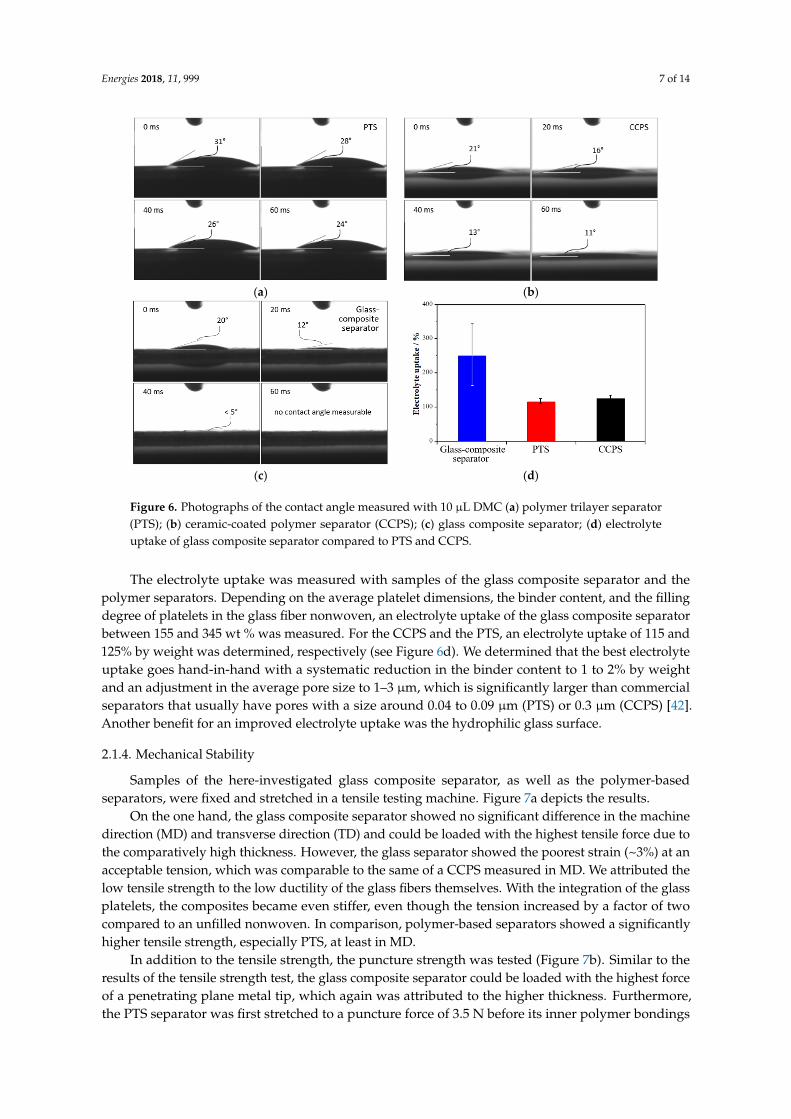
Since wetting of a separator with electrolyte is a dynamic process, it is necessary to observe how the wetting process evolves over time. Figure 6a–c are images of static contact angles of the glass composite separator and the compared polymer-based separators CCPS and PTS, taken at identical times after DMC contact (0 to 60 ms/20 ms steps). CCPS showed quite good wettability with DMC. A contact angle of 11–21° was observed. Owing to the non-polar surface charge of the used polymers, wetting of PTS took more time. Moreover, the average pore size of PTS was bigger than in CCPS. Consequently, a comparably high contact angle of >20° was measured, even after the same time that was needed for the CCPS to soak up all the DMC. The glass composite separator also showed very good wettability, as indicated by a rapidly decreasing contact angle that was always smaller than 20°. The defined amount of DMC was completely soaked in <50 ms. In comparison, 1–1.5 s for the CCPS and more than 60 s for the PTS were needed to soak the same amount of DMC.
Figure 5. Thermal stability of a glass fiber nonwoven/glass platelet composite separator, (a) temperature-dependent shrinkage (hot-oven test) compared to polymer-based separators; (b) thermogravimetric analysis;(c) behavior at exposures to 200 ◦C by heat radiation (hot-punch test); (d) demonstration of the flameretardation of the glass composite separator.
2.1.3. Wettability
The wettability of battery separators is crucial for fast cell manufacturing [42]. In order to evaluatethe wettability of the comparative separators, the contact angles, as well as the electrolyte uptake,were measured. As no measurement was possible using a standard battery electrolyte, the electrolytesolvent DMC (10 µL) served as the test liquid.
Since wetting of a separator with electrolyte is a dynamic process, it is necessary to observe howthe wetting process evolves over time. Figure 6a–c are images of static contact angles of the glasscomposite separator and the compared polymer-based separators CCPS and PTS, taken at identicaltimes after DMC contact (0 to 60 ms/20 ms steps). CCPS showed quite good wettability with DMC.A contact angle of 11–21◦ was observed. Owing to the non-polar surface charge of the used polymers,wetting of PTS took more time. Moreover, the average pore size of PTS was bigger than in CCPS.Consequently, a comparably high contact angle of >20◦ was measured, even after the same time thatwas needed for the CCPS to soak up all the DMC. The glass composite separator also showed verygood wettability, as indicated by a rapidly decreasing contact angle that was always smaller than 20◦.The defined amount of DMC was completely soaked in <50 ms. In comparison, 1–1.5 s for the CCPSand more than 60 s for the PTS were needed to soak the same amount of DMC.
Energies 2018, 11, 999 7 of 14
Energies 2018, 11, x FOR PEER REVIEW 7 of 14
(a)
(b)
(c)
(d)
Figure 6. Photographs of the contact angle measured with 10 µL DMC (a) polymer trilayer separator (PTS); (b) ceramic-coated polymer separator (CCPS); (c) glass composite separator; (d) electrolyte uptake of glass composite separator compared to PTS and CCPS. The electrolyte uptake was measured with samples of the glass composite separator and the
polymer separators. Depending on the average platelet dimensions, the binder content, and the filling degree of platelets in the glass fiber nonwoven, an electrolyte uptake of the glass composite separator between 155 and 345 wt % was measured. For the CCPS and the PTS, an electrolyte uptake of 115 and 125% by weight was determined, respectively (see Figure 6d). We determined that the best electrolyte uptake goes hand-in-hand with a systematic reduction in the binder content to 1 to 2% by weight and an adjustment in the average pore size to 1–3 µm, which is significantly larger than commercial separators that usually have pores with a size around 0.04 to 0.09 µm (PTS) or 0.3 µm (CCPS) [42]. Another benefit for an improved electrolyte uptake was the hydrophilic glass surface.
2.1.4. Mechanical Stability
Samples of the here-investigated glass composite separator, as well as the polymer-based separators, were fixed and stretched in a tensile testing machine. Figure 7a depicts the results.
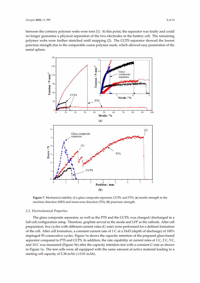
On the one hand, the glass composite separator showed no significant difference in the machine direction (MD) and transverse direction (TD) and could be loaded with the highest tensile force due to the comparatively high thickness. However, the glass separator showed the poorest strain (~3%) at an acceptable tension, which was comparable to the same of a CCPS measured in MD. We attributed the low tensile strength to the low ductility of the glass fibers themselves. With the integration of the glass platelets, the composites became even stiffer, even though the tension increased by a factor of two compared to an unfilled nonwoven. In comparison, polymer-based separators showed a significantly higher tensile strength, especially PTS, at least in MD.
In addition to the tensile strength, the puncture strength was tested (Figure 7b). Similar to the results of the tensile strength test, the glass composite separator could be loaded with the highest force of a penetrating plane metal tip, which again was attributed to the higher thickness. Furthermore, the PTS separator was first stretched to a puncture force of 3.5 N before its inner polymer bondings between the contrary polymer webs were torn (1). At this point, the separator was
Figure 6. Photographs of the contact angle measured with 10 µL DMC (a) polymer trilayer separator(PTS); (b) ceramic-coated polymer separator (CCPS); (c) glass composite separator; (d) electrolyteuptake of glass composite separator compared to PTS and CCPS.
The electrolyte uptake was measured with samples of the glass composite separator and thepolymer separators. Depending on the average platelet dimensions, the binder content, and the fillingdegree of platelets in the glass fiber nonwoven, an electrolyte uptake of the glass composite separatorbetween 155 and 345 wt % was measured. For the CCPS and the PTS, an electrolyte uptake of 115 and125% by weight was determined, respectively (see Figure 6d). We determined that the best electrolyteuptake goes hand-in-hand with a systematic reduction in the binder content to 1 to 2% by weightand an adjustment in the average pore size to 1–3 µm, which is significantly larger than commercialseparators that usually have pores with a size around 0.04 to 0.09 µm (PTS) or 0.3 µm (CCPS) [42].Another benefit for an improved electrolyte uptake was the hydrophilic glass surface.
2.1.4. Mechanical Stability
Samples of the here-investigated glass composite separator, as well as the polymer-basedseparators, were fixed and stretched in a tensile testing machine. Figure 7a depicts the results.
On the one hand, the glass composite separator showed no significant difference in the machinedirection (MD) and transverse direction (TD) and could be loaded with the highest tensile force due tothe comparatively high thickness. However, the glass separator showed the poorest strain (~3%) at anacceptable tension, which was comparable to the same of a CCPS measured in MD. We attributed thelow tensile strength to the low ductility of the glass fibers themselves. With the integration of the glassplatelets, the composites became even stiffer, even though the tension increased by a factor of twocompared to an unfilled nonwoven. In comparison, polymer-based separators showed a significantlyhigher tensile strength, especially PTS, at least in MD.
In addition to the tensile strength, the puncture strength was tested (Figure 7b). Similar to theresults of the tensile strength test, the glass composite separator could be loaded with the highest forceof a penetrating plane metal tip, which again was attributed to the higher thickness. Furthermore,the PTS separator was first stretched to a puncture force of 3.5 N before its inner polymer bondings
Energies 2018, 11, 999 8 of 14
between the contrary polymer webs were torn (1). At this point, the separator was faulty and couldno longer guarantee a physical separation of the two electrodes in the battery cell. The remainingpolymer webs were further stretched until snapping (2). The CCPS separator showed the lowestpuncture strength due to the comparable coarse polymer mesh, which allowed easy penetration of themetal sphere.
Energies 2018, 11, x FOR PEER REVIEW 8 of 14
faulty and could no longer guarantee a physical separation of the two electrodes in the battery cell. The remaining polymer webs were further stretched until snapping (2). The CCPS separator showed the lowest puncture strength due to the comparable coarse polymer mesh, which allowed easy penetration of the metal sphere.
(a)
(b)
Figure 7. Mechanical stability of a glass composite separator, CCPS, and PTS, (a) tensile strength in the machine direction (MD) and transverse direction (TD); (b) puncture strength.
2.2. Electrochemical Properties
The glass composite separator, as well as the PTS and the CCPS, was charged/discharged in a full-cell configuration setup. Therefore, graphite served as the anode and LFP as the cathode. After cell preparation, five cycles with different current rates (C-rate) were performed for a defined formation of the cell. After cell formation, a constant current rate of 1 C at a DoD (depth of discharge) of 100% impinged 95 consecutive cycles. Figure 8a shows the capacity retention of the prepared glass-based separator compared to PTS and CCPS. In addition, the rate capability at current rates of 1 C, 2 C, 5 C, and 10 C was measured (Figure 8b) after the capacity retention test with a constant C-rate as shown in Figure 8a. The test cells were all equipped with the same amount of active material leading to a starting cell capacity of 2.38 mAh (±0.01 mAh).
Figure 7. Mechanical stability of a glass composite separator, CCPS, and PTS, (a) tensile strength in themachine direction (MD) and transverse direction (TD); (b) puncture strength.
2.2. Electrochemical Properties
The glass composite separator, as well as the PTS and the CCPS, was charged/discharged in afull-cell configuration setup. Therefore, graphite served as the anode and LFP as the cathode. After cellpreparation, five cycles with different current rates (C-rate) were performed for a defined formationof the cell. After cell formation, a constant current rate of 1 C at a DoD (depth of discharge) of 100%impinged 95 consecutive cycles. Figure 8a shows the capacity retention of the prepared glass-basedseparator compared to PTS and CCPS. In addition, the rate capability at current rates of 1 C, 2 C, 5 C,and 10 C was measured (Figure 8b) after the capacity retention test with a constant C-rate as shownin Figure 8a. The test cells were all equipped with the same amount of active material leading to astarting cell capacity of 2.38 mAh (±0.01 mAh).
Energies 2018, 11, 999 9 of 14Energies 2018, 11, x FOR PEER REVIEW 9 of 14
(a)
(b)
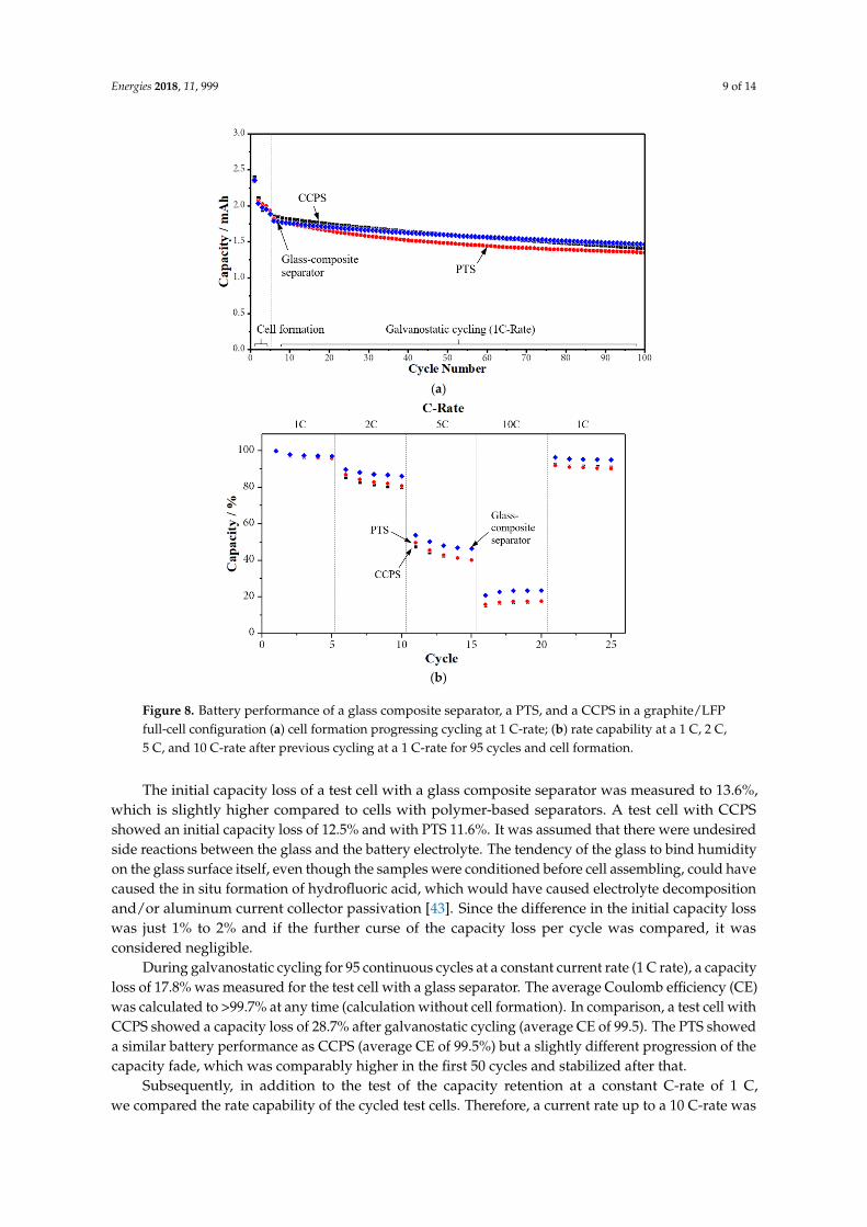
Figure 8. Battery performance of a glass composite separator, a PTS, and a CCPS in a graphite/LFP full-cell configuration (a) cell formation progressing cycling at 1 C-rate; (b) rate capability at a 1 C, 2 C, 5 C, and 10 C-rate after previous cycling at a 1 C-rate for 95 cycles and cell formation.
The initial capacity loss of a test cell with a glass composite separator was measured to 13.6%, which is slightly higher compared to cells with polymer-based separators. A test cell with CCPS showed an initial capacity loss of 12.5% and with PTS 11.6%. It was assumed that there were undesired side reactions between the glass and the battery electrolyte. The tendency of the glass to bind humidity on the glass surface itself, even though the samples were conditioned before cell assembling, could have caused the in situ formation of hydrofluoric acid, which would have caused electrolyte decomposition and/or aluminum current collector passivation [43]. Since the difference in the initial capacity loss was just 1% to 2% and if the further curse of the capacity loss per cycle was compared, it was considered negligible.
During galvanostatic cycling for 95 continuous cycles at a constant current rate (1 C rate), a capacity loss of 17.8% was measured for the test cell with a glass separator. The average Coulomb efficiency (CE) was calculated to >99.7% at any time (calculation without cell formation). In comparison, a test cell with CCPS showed a capacity loss of 28.7% after galvanostatic cycling (average CE of 99.5). The PTS showed a similar battery performance as CCPS (average CE of 99.5%) but a slightly different progression of the capacity fade, which was comparably higher in the first 50 cycles and stabilized after that.
Figure 8. Battery performance of a glass composite separator, a PTS, and a CCPS in a graphite/LFPfull-cell configuration (a) cell formation progressing cycling at 1 C-rate; (b) rate capability at a 1 C, 2 C,5 C, and 10 C-rate after previous cycling at a 1 C-rate for 95 cycles and cell formation.
The initial capacity loss of a test cell with a glass composite separator was measured to 13.6%,which is slightly higher compared to cells with polymer-based separators. A test cell with CCPSshowed an initial capacity loss of 12.5% and with PTS 11.6%. It was assumed that there were undesiredside reactions between the glass and the battery electrolyte. The tendency of the glass to bind humidityon the glass surface itself, even though the samples were conditioned before cell assembling, could havecaused the in situ formation of hydrofluoric acid, which would have caused electrolyte decompositionand/or aluminum current collector passivation [43]. Since the difference in the initial capacity losswas just 1% to 2% and if the further curse of the capacity loss per cycle was compared, it wasconsidered negligible.
During galvanostatic cycling for 95 continuous cycles at a constant current rate (1 C rate), a capacityloss of 17.8% was measured for the test cell with a glass separator. The average Coulomb efficiency (CE)was calculated to >99.7% at any time (calculation without cell formation). In comparison, a test cell withCCPS showed a capacity loss of 28.7% after galvanostatic cycling (average CE of 99.5). The PTS showeda similar battery performance as CCPS (average CE of 99.5%) but a slightly different progression of thecapacity fade, which was comparably higher in the first 50 cycles and stabilized after that.
Subsequently, in addition to the test of the capacity retention at a constant C-rate of 1 C,we compared the rate capability of the cycled test cells. Therefore, a current rate up to a 10 C-rate was
Energies 2018, 11, 999 10 of 14
applied. The rate capability of a test cell with the described glass composite separator was comparedto CCPS and PTS (Figure 8b). Concerning the test cell with the glass separator, an average capacityof 23% was charged/discharged at a 10 C-rate, whereas a test cell with a CCPS or a PTS separatorwas charged only up to 16–17% of capacity. Similar effects were shown at current rates of 2 C and5 C, respectively. After cycling at a 10 C rate, five cycles at a 1 C rate were performed. The test cellwith a the glass composite separator showed a total capacity loss of 4.5% as part of this test, while thecapacity of the comparative test cells with a CCPS or a PTS was degraded to 8.5 and 9%, respectively.
In summary, the capacity retention, as well as the rate capability of test cells with the glasscomposite separator, was slightly improved compared to cells with polymer-based separators. Besidesthe physical properties such as the bigger pore sizes and the easy wetting or bigger solvent uptake ofthe glass separator, we attributed this improvement to the interaction between the glass and batteryelectrolytes. It is known that specific electrolyte additives can enhance the performance of lithium-ionbatteries [44]. It is assumed that ions from the glass, which are dissolved in the electrolyte in unexpectedside reactions, are responsible for the improved electrochemical behavior.
3. Materials and Methods
3.1. Materials
The glass (Telux Glasproducts & Components GmbH, Weißwasser, Germany) for preparing theglass platelets was a sodium borosilicate glass with traces of zirconium oxide, aluminum oxide, titaniumoxide, potassium oxide, and barium oxide. Further details are described in [41]. A glass fiber nonwovenwas purchased (Johns Manville Corp., Denver, CO, USA). As a binder, water-based sodium alginate(Sigma Aldrich, St. Louis, MO, USA) was used. A graphite-coated copper foil served as the anode,the cathode consisted of an aluminum foil with a lithium iron phosphate coating. Both electrodes werecommercially obtained (Customcells Itzehoe GmbH, Itzehoe, Germany) in the balanced configuration(2.2 mAh/cm2 for the graphite, 2.0 mAh/cm2 for the LFP). A commercial LP30 served as the electrolyte(1:1 EC:DMC, 1 mol dm−3 LiPF6; Merck & Co., Kenilworth, NJ, USA). A ceramic-coated PET-nonwovenseparator (Separion® S240P30; Evonik Industries AG, Essen, Germany) denoted as CCPS (thickness28.5 µm) and a polymer trilayer (Celgard® 2325, Celgard LLC, Charlotte, NC, USA) denoted as PTS(thickness 25 µm) were used to compare our data with commercially available separators.
3.2. Preparation of a Glass Platelet—Glass Fiber Nonwoven Composite Separator
To manufacture the micrometer-sized glass platelets, a rotary atomization process was used.The glass was melted at 1350 ◦C in a glass melting tank. After melting, the glass melt was then fed intoa rotating and preheated atomizer (cup-shaped). Due to the rotation of the atomizer, the glass meltwas pushed outwards over the edge of the atomizer and formed lamellae. These lamellae were furtherstretched and simultaneously quenched until the glass broke, resulting in micrometer-sized glassplatelets. Further details of the process are described by Kyrgyzbaev et al. [45] and Schadeck et al. [41].
The glass platelets (average thickness <5 µm) were ground and sorted by particle size. Plateletswith an average particle size <32 µm were used to prepare the glass composite separator. The binderwas obtained by stirring a defined amount of sodium alginate with deionized water (ratio 1:9) for 48 hat room temperature. After that, the binder was mixed with the glass platelets in a centrifugal mixer(Thinky Mixer ARE 250 CE, Laguna Hill, CA, USA) for 5 min/1200 rpm to obtain a homogeneousslurry. Then, a doctor blade was used to cast the glass platelet-binder slurry inside the glass fibernonwoven at a feed speed of 2.5 mm s−1. Therefore, the height of the doctor blade was adjusted to90% of the premeasured height of the glass fiber nonwoven. Finally, the composites were conditionedin a vacuum furnace at 80 ◦C for at least 4 h. To prepare samples for electrochemical characterizations,discs (Ø 12 mm) were punched.
Energies 2018, 11, 999 11 of 14
3.3. Characterization
The samples of the glass composite separators, as well as the previously punched electrodematerials, were conditioned in a tube furnace in a constant flow of Argon (10 dm3 h−1) at 110 ◦C for12 h in order to remove any moisture.
Thermogravimetric analysis (TGA; Netzsch, Selb, Germany) was conducted up to 585 ◦C (heatingrate 10 ◦C min−1; air flow 3 dm3 h−1). The thermal stability of the various separators was determinedby measuring the dimensional change of samples (30 mm square) after being exposed to varioustemperatures up to 600 ◦C for 30 min each. The shrinkage Srel was calculated by Equation (1):
Srel (%) =A1 − A0
A0× 100 (1)
wherein A0 and A1 denote the sample surface area before/after the heat treatment. Additionally,and according to [11], a so-called hot punch test was performed where the separator samples were put3 mm under a preheated metal tip (200 ◦C, diameter 2 mm) for 1 min.
To obtain data of the wettability of the separators, the contact angles were determined. Here,a defined amount of organic solvent (10 µL DMC) was dropped on the samples and the contact anglewas measured using a static digital photograph taken by the identical time after electrolyte contact(20 ms). The electrolyte uptake urel was calculated by Equation (2). Therefore, the weight of the samplesbefore (m0) and after (m) wetting (2 h soaking) was measured.
urel (%) =m0 − m
m0× 100 (2)
The morphologies of the glass platelets, the glass fiber nonwoven, as well as the compositemembranes, were investigated using a scanning electron microscope (SEM; JSM-840A, JEOL Ltd., Tokyo,Japan) at an acceleration voltage of 10 kV. The porosity and the average pore diameters of the glasscomposite separator samples were obtained by gas adsorption (Micromeritics, ASAP 2010, Norcross, GA,USA) and Hg-porosimetry (Micromeritics Auto Pore 9410, Pore-Core, Norcross, GA, USA).
Furthermore, the mechanical stability of the glass composite membrane in comparison to thecommercial polymer-based separators was tested. The tensile strength was measured in both the machinedirection (MD) and in the transverse direction (TD) where a clamped piece of the separator (20 × 80 mm)was stretched (Series 5569, Instron, Norwood, MA, USA) with a feed speed of 1 mm min−1. Additionally,the puncture strength was observed by penetrating the membranes with a rounded steel tip (Ø 2 mm).Therefore, discs (Ø 14 mm) of the various separators where fixed between two steel flat washers in anopen Swagelok 1/2” tube fitting.
To investigate the electrochemical parameters, the samples of the glass composite andthe commercial polyolefin-based separators were mounted in a Swagelok® 1/2” tube fitting.Commercial graphite served as the anode and LFP as the cathode (full-cell configuration).The graphite/separator/LFP-sandwich was fixed between two custom-made stainless steel electrodes.The cells were prepared under inert gas conditions in a glovebox.
The capacity retention, as well as the rate capability of the test cells with various separators,was tested in a battery test system (CTS-LAB, BaSyTec GmbH, Asselfingen, Germany). At first, the testcells were formatted (5 cycles; 2 × 0.1 C, 2 × 0.5 C, 1 × 1 C) according to the electrode materials’manufacturer’s data sheet. The cell potential served as the termination criterion (3.8 V/2.5 V). For allcycles, a DoD (depth of discharge) of 100% was used. After cell formation, the capacity retention wasobserved for 95 cycles at a 1 C-rate. The rate capability measurement was conducted after the capacityretention test, wherein different current rates (1 C, 2 C, 5 C, and 10 C) were applied for five cycles each.For that, the same potential range and a DoD of 100% were used as well.
Energies 2018, 11, 999 12 of 14
4. Conclusions
A novel type of glass-based separator was prepared using a glass fiber nonwoven withintegrated custom-made micrometer-sized glass platelets as a high-temperature stable alternativeto polymer-based separators. The physical properties, as well as the battery performance ina graphite/LFP full-cell setup, were tested. Correspondingly, the results were compared topolymer-based separators. The presented glass composite separator is flexible, flame-retardant,and stable up to 600 ◦C, shows almost no shrinkage (~2%), and is still mechanically stable. Furthermore,fast wetting of non-aqueous electrolytes was observed. The glass composite separator was soakedwith organic solvent 20 and 1200 times faster than typical ceramic-coated polymer separators andpolymer trilayer separators, respectively. On the other hand, the thickness of the glass compositemembrane, as well as the tensile strength, needs to be further improved, even though the results of thepuncture strength tests are quite promising. The electrochemical properties of a graphite/LFP full-cellconfiguration setup were excellent. The Coulomb efficiency was still above 99.7% at a 1 C-rate duringgalvanostatic cycling and the overall capacity retention was equal and even slightly higher than thetypical polymer separators. During rate capability tests, a capacity of 23% was charged/discharged ata 10 C rate, whereas cells with typical polymer-based separators were charged only to 17% of capacity.
It was shown that a glass-based separator made from glass fiber nonwovens with integratedglass platelets is a suitable, high-temperature-stable separator with good battery performance and anexcellent wettability for fast cell manufacturing.
Acknowledgments: The financial support by the BayNW project ACoS (PTJ-1308-0002) and the further financialsupport as part of a graduate program of the TechnologieAllianzOberfranken (TAO) is gratefully acknowledged.This publication was funded by the German Research Foundation (DFG) and the University of Bayreuth in thefunding program Open Access Publishing. This work is dedicated to Monika Willert-Porada who passed away in2016. We kindly would like to thank her for her contribution to the project and for her support.
Author Contributions: Ulrich Schadeck wrote the paper and performed all experiments; Kanat Kyrgyzbaevhelped in preparing the glass platelets; Heiko Zettl provided the glass fiber nonwoven, shared his know-how aboutbinders, and successfully tested the preparation of glass composite separators in industrial roll-to-roll processes;Thorsten Gerdes initiated the above-mentioned project; Ralf Moos, Thorsten Gerdes, Heiko Zettl, and KanatKyrgyzbaev provided guidance, discussed the collected data, helped in manuscript preparation, and decided onthe next steps.
Conflicts of Interest: The authors declare no conflicts of interest.
References
1. Lu, L.; Han, X.; Li, J.; Hua, J.; Ouyang, M. A review on the key issues for lithium-ion battery management inelectric vehicles. J. Power Sources 2013, 226, 272–288. [CrossRef]
2. Park, J.-K. (Ed.) Principles and Applications of Lithium Secondary Batteries; Wiley-VCH: Weinheim, Germany,2012; ISBN 978-3-52-733151-2. [CrossRef]
3. Linden, D.; Reddy, T.B. (Eds.) Linden’s Handbook of Batteries, 4th ed.; McGraw-Hill: New York, NY, USA, 2011;ISBN 978-0-07-162421-3.
4. Cairns, E.J.; Albertus, P. Batteries for electric and hybrid-electric vehicles. Annu. Rev. Chem. Biomol. Eng.2010, 1, 299–320. [CrossRef] [PubMed]
5. Gerssen-Gondelach, S.J.; Faaij, A.P.C. Performance of batteries for electric vehicles on short and longer term.J. Power Sources 2012, 212, 111–129. [CrossRef]
6. Abada, S.; Marlair, G.; Lecocq, A.; Petit, M.; Sauvant-Moynot, V.; Huet, F. Safety focused modeling oflithium-ion batteries, A review. J. Power Sources 2016, 306, 178–192. [CrossRef]
7. Nazri, G.-A.; Pistoia, G. (Eds.) Lithium Batteries: Science and Technology, 1st ed.; Springer: New York, NY, USA,2009; ISBN 978-0-38-792675-9.
8. Loveridge, M.; Remy, G.; Kourra, N.; Genieser, R.; Barai, A.; Lain, M.; Guo, Y.; Amor-Segan, M.; Williams, M.;Amietszajew, T.; et al. Looking Deeper into the Galaxy (Note 7). Batteries 2018, 4, 3. [CrossRef]
9. Huang, X. Separator technologies for lithium-ion batteries. J. Solid State Electrochem. 2011, 15, 649–662.[CrossRef]
Energies 2018, 11, 999 13 of 14
10. Yang, M.; Hou, J. Membranes in lithium ion batteries. Membranes 2012, 2, 367–383. [CrossRef] [PubMed]11. Shi, C.; Zhang, P.; Chen, L.; Yang, P.; Zhao, J. Effect of a thin ceramic-coating layer on thermal and
electrochemical properties of polyethylene separator for lithium-ion batteries. J. Power Sources 2014, 270,547–553. [CrossRef]
12. Roth, E.P.; Doughty, D.H.; Pile, D.L. Effects of separator breakdown on abuse response of 18,650 Li-ion cells.J. Power Sources 2007, 174, 579–583. [CrossRef]
13. Kim, J.Y.; Lim, D.Y. Surface-Modified Membrane as a Separator for Lithium-Ion Polymer Battery. Energies2010, 3, 866–885. [CrossRef]
14. Huang, F.; Liu, W.; Li, P.; Ning, J.; Wei, Q. Electrochemical Properties of LLTO/Fluoropolymer-ShellCellulose-Core Fibrous Membrane for Separator of High Performance Lithium-Ion Battery. Materials 2016,9, 75. [CrossRef] [PubMed]
15. Choi, J.-A.; Kim, S.H.; Kim, D.-W. Enhancement of thermal stability and cycling performance in lithium-ioncells through the use of ceramic-coated separators. J. Power Sources 2010, 195, 6192–6196. [CrossRef]
16. Shi, C.; Dai, J.; Li, C.; Shen, X.; Peng, L.; Zhang, P.; Wu, D.; Sun, D.; Zhao, J. A Modified Ceramic-CoatingSeparator with High-Temperature Stability for Lithium-Ion Battery. Polymers 2017, 9, 159. [CrossRef]
17. Zhai, Y.; Xiao, K.; Yu, J.; Ding, B. Fabrication of hierarchical structured SiO2/polyetherimide-polyurethanenanofibrous separators with high performance for lithium ion batteries. Electrochim. Acta 2015, 154, 219–226.[CrossRef]
18. Yeon, D.; Lee, Y.; Ryou, M.-H.; Lee, Y.M. New flame-retardant composite separators based on metalhydroxides for lithium-ion batteries. Electrochim. Acta 2015, 157, 282–289. [CrossRef]
19. Yanilmaz, M.; Zhang, X. Polymethylmethacrylate/Polyacrylonitrile Membranes via Centrifugal Spinning asSeparator in Li-Ion Batteries. Polymers 2015, 7, 629–643. [CrossRef]
20. Yanilmaz, M.; Dirican, M.; Zhang, X. Evaluation of electrospun SiO2/nylon 6,6 nanofiber membranes as athermally-stable separator for lithium-ion batteries. Electrochim. Acta 2014, 133, 501–508. [CrossRef]
21. Shi, C.; Dai, J.; Huang, S.; Li, C.; Shen, X.; Zhang, P.; Wu, D.; Sun, D.; Zhao, J. A simple method to prepare apolydopamine modified core-shell structure composite separator for application in high-safety lithium-ionbatteries. J. Membr. Sci. 2016, 518, 168–177. [CrossRef]
22. Lee, J.; Lee, C.-L.; Park, K.; Kim, I.-D. Synthesis of an Al2O3-coated polyimide nanofiber mat and itselectrochemical characteristics as a separator for lithium ion batteries. J. Power Sources 2014, 248, 1211–1217.[CrossRef]
23. Jiang, W.; Liu, Z.; Kong, Q.; Yao, J.; Zhang, C.; Han, P.; Cui, G. A high temperature operating nanofibrouspolyimide separator in Li-ion battery. Solid State Ion. 2013, 232, 44–48. [CrossRef]
24. Song, J.; Ryou, M.-H.; Son, B.; Lee, J.-N.; Lee, D.J.; Lee, Y.M.; Choi, J.W.; Park, J.-K. Co-polyimide-coatedpolyethylene separators for enhanced thermal stability of lithium ion batteries. Electrochim. Acta 2012, 85,524–530. [CrossRef]
25. Miao, Y.-E.; Zhu, G.-N.; Hou, H.; Xia, Y.-Y.; Liu, T. Electrospun polyimide nanofiber-based nonwovenseparators for lithium-ion batteries. J. Power Sources 2013, 226, 82–86. [CrossRef]
26. Smith, S.A.; Williams, B.P.; Joo, Y.L. Effect of polymer and ceramic morphology on the material andelectrochemical properties of electrospun PAN/polymer derived ceramic composite nanofiber membranesfor lithium ion battery separators. Annu. Rev. Chem. Biomol. Eng. 2017, 526, 315–322. [CrossRef]
27. Khan, W.S.; Asmatulu, R.; Rodriguez, V.; Ceylan, M. Enhancing thermal and ionic conductivities ofelectrospun PAN and PMMA nanofibers by graphene nanoflake additions for battery-separator applications.Int. J. Energy Res. 2014, 38, 2044–2051. [CrossRef]
28. Yanilmaz, M.; Lu, Y.; Li, Y.; Zhang, X. SiO2/polyacrylonitrile membranes via centrifugal spinning as aseparator for Li-ion batteries. J. Power Sources 2015, 273, 1114–1119. [CrossRef]
29. Lee, J.H.; Manuel, J.; Choi, H.; Park, W.H.; Ahn, J.-H. Partially oxidized polyacrylonitrile nanofibrousmembrane as a thermally stable separator for lithium ion batteries. Polymer 2015, 68, 335–343. [CrossRef]
30. Wang, Q.; Yu, Y.; Ma, J.; Zhang, N.; Zhang, J.; Liu, Z.; Cui, G. Electrospun melamine resin-based multifunctionalnonwoven membrane for lithium ion batteries at the elevated temperatures. J. Power Sources 2016, 327, 196–203.[CrossRef]
31. Carvalho, D.V.; Loeffler, N.; Kim, G.-T.; Passerini, S. High Temperature Stable Separator for Lithium BatteriesBased on SiO2 and Hydroxypropyl Guar Gum. Membranes 2015, 5, 632–645. [CrossRef] [PubMed]
Energies 2018, 11, 999 14 of 14
32. Luo, X.; Pan, W.; Liu, H.; Gong, J.; Wu, H. Glass fiber fabric mat as the separator for lithium-ion battery withhigh safety performance. Ionics 2015, 21, 3135–3139. [CrossRef]
33. Jung, Y.-C.; Kim, S.-K.; Kim, M.-S.; Lee, J.-H.; Han, M.-S.; Kim, D.-H.; Shin, W.-C.; Ue, M.; Kim, D.-W. Ceramicseparators based on Li+-conducting inorganic electrolyte for high-performance lithium-ion batteries withenhanced safety. J. Power Sources 2015, 293, 675–683. [CrossRef]
34. Brigham, S.J.; Watkinson, C. Understanding and use of glass flake. Paint Coat. Ind. 2009, 25, 22–24.35. Anselmann, R.; Ambrosius, K.; Mathias, M. Effect Pigments Based on Coated Glass Flakes. U.S. Patent
7,226, 503, 5 June 2007.36. Koronis, G.; Silva, A.; Fontul, M. Green composites, a review of adequate materials for automotive
applications. Composites Part B 2013, 44, 120–127. [CrossRef]37. Kaynakli, O. A review of the economical and optimum thermal insulation thickness for building applications.
Renew. Sustain. Energy Rev. 2012, 16, 415–425. [CrossRef]38. Aleksic, B.; Bailly, S.; Draghi, M.; Pestka, J.J.; Oswald, I.P.; Robine, E.; Bailly, J.D.; Lacroix, M.Z. Production
of four macrocyclic trichothecenes by Stachybotrys chartarum during its development on different buildingmaterials as measured by UPLC-MS/MS. Build. Environ. 2016, 106, 265–273. [CrossRef]
39. Kumar, V.; Rao, P.K.; Rawal, A. Amplification of electrolyte uptake in the absorptive glass mat (AGM)separator for valve regulated lead acid (VRLA) batteries. J. Power Sources 2017, 341, 19–26. [CrossRef]
40. Zhu, J.; Yanilmaz, M.; Fu, K.; Chen, C.; Lu, Y.; Ge, Y.; Kim, D.; Zhang, X. Understanding glass fiber membraneused as a novel separator for lithium–sulfur batteries. J. Membr. Sci. 2016, 504, 89–96. [CrossRef]
41. Schadeck, U.; Kyrgyzbaev, K.; Gerdes, T.; Willert-Porada, M.; Moos, R. Porous and non-porousmicrometer-sized glass platelets as separators for lithium-ion batteries. J. Membr. Sci. 2018, 550, 518–525.[CrossRef]
42. Zhang, S.S. A review on the separators of liquid electrolyte Li-ion batteries. J. Power Sources 2007, 164,351–364. [CrossRef]
43. Cho, E.; Mun, J.; Chae, O.B.; Kwon, O.M.; Kim, H.-T.; Ryu, J.H.; Kim, Y.G.; Oh, S.M. Corrosion/passivationof aluminum current collector in bis(fluorosulfonyl)imide-based ionic liquid for lithium-ion batteries.Electrochem. Commun. 2012, 22, 1–3. [CrossRef]
44. Zhang, S.S. A review on electrolyte additives for lithium-ion batteries. J. Power Sources 2006, 162, 1379–1394.[CrossRef]
45. Kyrgyzbaev, K.; Rosin, A.; Willert-Porada, M. Influence of temperature on the thickness of ultrathinparticulate glass platelets. Glass Technol. Eur. J. Glass Sci. Technol. Part A 2016, 57, 95–100. [CrossRef]
© 2018 by the authors. Licensee MDPI, Basel, Switzerland. This article is an open accessarticle distributed under the terms and conditions of the Creative Commons Attribution(CC BY) license (http://creativecommons.org/licenses/by/4.0/).