flexible learning approach to physics ÊÊÊ module p6.4 ... · study comment having read the...
TRANSCRIPT

F L E X I B L E L E A R N I N G A P P R O A C H T O P H Y S I C S
FLAP P6.4 Optical instrumentsCOPYRIGHT © 1998 THE OPEN UNIVERSITY S570 V1.1
Module P6.4 Optical instruments1 Opening items
1.1 Module introduction
1.2 Fast track questions
1.3 Ready to study?
2 Magnification, aberration and resolution
2.1 Magnification
2.2 Aberrations of lenses and mirrors
2.3 Resolution and angular resolving power: the Rayleigh criterion
3 The eye
3.1 The structure of the eye
3.2 Defects of vision: long sight and short sight
4 Some simple optical instruments
4.1 The magnifying glass
4.2 The pinhole camera
5 Some more complex optical instruments
5.1 The camera
5.2 The compound microscope
5.3 The refracting telescope
5.4 Binoculars
5.5 The reflecting telescope
5.6 The spectrometer
6 Closing items
6.1 Module summary
6.2 Achievements
6.3 Exit test
Exit module

FLAP P6.4 Optical instrumentsCOPYRIGHT © 1998 THE OPEN UNIVERSITY S570 V1.1
1 Opening items
1.1 Module introductionThis module begins with a discussion of magnification, aberration and resolution and moves on to show howthese concepts are important in the design of a variety of optical instruments, including the eye. Throughoutmost of the module we treat light as travelling in rays, because geometrical optics is the most useful way toapproach optical instruments. The main exception is in the discussion of resolution and angular resolving power,where the wave aspects of light are paramount. There are a number of suggested simple experiments which youmay like to try whilst working through the module; these will give you a better ‘feel’ for the phenomena, butthey are optional.
Section 2 defines three different measures of magnification1—1transverse magnification, angular magnificationand magnifying power1—1and describes the appropriate situations in which they can be applied. Practical opticalinstrument design must successfully limit the effects of the various aberrations present in real lenses and mirrors,including spherical aberration, coma and chromatic aberration. The first two may be reduced by careful designof the refracting or reflecting surfaces whilst the third is minimized for lenses by using achromatic doublets.Section 2 also describes resolution and angular resolving power, as being limited by diffraction, and introducesthe Rayleigh criterion of resolution.
FLAP P6.4 Optical instrumentsCOPYRIGHT © 1998 THE OPEN UNIVERSITY S570 V1.1
Section 3 describes the structure and function of the eye, along with its most common deficiencies of long sightand short sight. Several of the more subtle features of the eye are mentioned, including how its graded index lensreduces spherical aberration, how its resolution is limited and how depth perception is achieved.
Section 4 describes some simple optical instruments, including the magnifying glass and the pinhole camera.This leads, in Section 5, to the photographic camera and a comparison of its function with that of the eye.In this section also is the main discussion of the more important instruments which use more than a singleoptical component. This discussion includes the compound microscope, the refracting telescope, binoculars,various designs of reflecting telescope and finally the spectrometer.
Study comment Having read the introduction you may feel that you are already familiar with the material covered by thismodule and that you do not need to study it. If so, try the Fast track questions given in Subsection 1.2. If not, proceeddirectly to Ready to study? in Subsection 1.3.

FLAP P6.4 Optical instrumentsCOPYRIGHT © 1998 THE OPEN UNIVERSITY S570 V1.1
1.2 Fast track questions
Study comment Can you answer the following Fast track questions?. If you answer the questions successfully you needonly glance through the module before looking at the Module summary (Subsection 6.1) and the Achievements listed inSubsection 6.2. If you are sure that you can meet each of these achievements, try the Exit test in Subsection 6.3. If you havedifficulty with only one or two of the questions you should follow the guidance given in the answers and read the relevantparts of the module. However, if you have difficulty with more than two of the Exit questions you are strongly advised tostudy the whole module.
Question F1
Sketch the ray diagram for the arrangement of lenses in a simple refracting astronomical telescope to show howan image is formed. Explain how the ability of a telescope to resolve small features on the object depends on thesize of the telescope’s objective. Why is the eyepiece normally adjusted so that the final image is formed atinfinity?

FLAP P6.4 Optical instrumentsCOPYRIGHT © 1998 THE OPEN UNIVERSITY S570 V1.1
Question F2
With the aid of a diagram, describe what is meant by an achromatic doublet and say how this can be used tocorrect for lens aberrations.
Question F3
Distinguish between the terms transverse magnification, angular magnification and magnifying power.Which would be the appropriate term to describe the magnification produced by: (a) a microscope;(b) the lens of a film projector; (c) a telescope?
FLAP P6.4 Optical instrumentsCOPYRIGHT © 1998 THE OPEN UNIVERSITY S570 V1.1
Study comment Having seen the Fast track questions you may feel that it would be wiser to follow the normal routethrough the module and to proceed directly to Ready to study? in Subsection 1.3.
Alternatively, you may still be sufficiently comfortable with the material covered by the module to proceed directly to theClosing items.

FLAP P6.4 Optical instrumentsCOPYRIGHT © 1998 THE OPEN UNIVERSITY S570 V1.1
1.3 Ready to study?
Study comment To begin the study of this module you will need to be familiar with the following terms: diffraction,diffraction grating, dispersion, electromagnetic spectrum, focal length, focal point, geometrical optics, lenses (spherical,concave/convex, biconvex, thin lens, planoconvex, lens maker’s equation), mirrors (spherical, concave/convex), objects andimages (real object0/image, virtual object0/image, inverted, erect, object0/image distance), optical axis, paraxial, prism, ray,refraction, refractive index, spherical mirror equation, thin lens equation, total internal reflection and wavelength. If you areuncertain about any of these terms then you can review them now by referring to the Glossary, which will indicate where inFLAP they are introduced. The following Ready to study questions will allow you to establish whether you need to reviewsome of the topics before embarking on the module.

FLAP P6.4 Optical instrumentsCOPYRIGHT © 1998 THE OPEN UNIVERSITY S570 V1.1
Question R1
A thin converging lens of focal length 81cm is used to form an image of an object 21cm in height, which is placed121cm away from the lens along the optical axis. Using a ray diagram, drawn to scale, determine the finalposition of the image, its nature (real or virtual), size and orientation (erect or inverted).
Question R2
A thin converging lens of focal length 61cm is used to produce a magnified image of a flea situated on the opticalaxis of the lens a distance of 41cm from its centre. Using the thin lens equation, determine the position, nature(real or virtual) and orientation (erect or inverted) of the image.
Question R3
A thin diverging lens of focal length 101cm is used to form an image of an object 31cm in height, placed at adistance of 121cm from the centre of the lens. Sketch the ray diagram showing the image production.

FLAP P6.4 Optical instrumentsCOPYRIGHT © 1998 THE OPEN UNIVERSITY S570 V1.1
Question R4
A thin beam of white light is allowed to strike a triangular prism so that dispersion takes place. With the aid of adiagram show the effect this has on the beam of white light. What conclusions may be drawn concerning thespeed of propagation of the different colours which make up white light?
Question R5
A small object is placed on the optical axis, 201cm away from a concave mirror with radius of curvature 151cm.Describe qualitatively the nature and position of the image formed and indicate how this will change as theobject is moved along the axis towards the mirror, so that it reaches a final position 101cm from the mirror.

FLAP P6.4 Optical instrumentsCOPYRIGHT © 1998 THE OPEN UNIVERSITY S570 V1.1
2 Magnification, aberration and resolutionThe function of optical instruments is to extend the performance of the human eye in a variety of ways.For example, we may need to magnify the view of an object, if it is too small (using a microscope) or if it isvery far away (using a telescope), or we may need a permanent record (obtained using camera), or moreinformation about the colour composition of the light from the object (as revealed by a spectrometer).In conjunction with these devices we may need to replace the eye by a completely different detector of the light,because the eye is too insensitive or otherwise inadequate. For example, the object may be too dim to be seen orits electromagnetic radiation may lie outside the visible spectrum; both these situations require other devices(such as photomultipliers) which often replace the eye altogether. It is sensible to separate the function of theoptical instrument from that of the detector, admitting of course that at some stage both are required.The optical instrument produces an image of an object and this image must then be detected in some way.
In the eye itself, the two functions of image production and detection are combined in a very compact butcomplex way and evolution has optimized its design; some of the subtleties of this design will become apparentin this module. We will look at the eye as an optical instrument in Section 3 but before this we need to set out afew general considerations which are needed in the design of any optical instrument which produces its imagesusing lenses or mirrors.

FLAP P6.4 Optical instrumentsCOPYRIGHT © 1998 THE OPEN UNIVERSITY S570 V1.1
2.1 MagnificationProbably the simplest and most widely used optical instrument is the simple magnifying glass (this will bediscussed further in Subsection 4.1). This is a single convex (converging) lens which helps us see objects bymaking them appear larger. More complex optical instruments also often magnify the view of an object, but howshould this magnification be characterized? There are three main ways in which the magnification of an opticalinstrument can be defined but not all of them are sensible to use in a given situation. These three definitionsintroduce three different measures of magnification: transverse magnification, angular magnification a n dmagnifying power.

FLAP P6.4 Optical instrumentsCOPYRIGHT © 1998 THE OPEN UNIVERSITY S570 V1.1
image
h'
h
u
object
v(a)
Figure 1a3Transverse magnification is the ratio of image and objectheights;
When an optical system produces an image ofan object, then the ratio of the transversedimension of the image to that of the object iscalled the transverse magnification.For example, if the object and image arelinked by a single lens, as shown inFigure 1a, with u and v being the object andimage distances, respectively, then:
transverse magnification
Mtran = ′h
h= v
u(1) ☞
where we have used the similar triangles in the diagram. While the transverse magnification seems an obviousdefinition to use there are two problems with it. First, Equation 1 shows that it is a meaningless quantity if eitherthe object or image is situated at infinity; both must be at finite distances. Secondly, the transverse magnificationdoes not, in general, relate directly to the magnification perceived by the eye unless the object and image are atthe same distance from the eye.

FLAP P6.4 Optical instrumentsCOPYRIGHT © 1998 THE OPEN UNIVERSITY S570 V1.1
image
h'
h
object
z(b)
θo
θ I
z'
Figure 1b3Angular magnification is the ratio of the angles subtendedby image and object at the eye
It is a matter of common experience that thenearer an object is to our eye, the larger itappears to be. A five pence piece held atarm’s length appears to be about the samesize as the Moon, because both subtend aboutthe same angle, 1°, at the eye. In an opticalinstrument the perceived magnification willbe set by the relative sizes of the anglessubtended by the image and the object at theeye, or by the angular magnification, asshown in Figure 1b and defined in Equation2.
angular magnification
Mang = θI
θO≈ tanθI
tanθO= ′h ′z
h z(2) ☞
The magnification of a telescope is best characterized by its angular magnification, as we will see in Subsection5.3.
FLAP P6.4 Optical instrumentsCOPYRIGHT © 1998 THE OPEN UNIVERSITY S570 V1.1
As an object is brought nearer and nearer to the eye, it will subtend a larger and larger angle at the eye, and soappear larger. This procedure is limited because at a certain minimum distance it becomes impossible for the eyeto focus on the object. This distance is called the least distance of distinct vision (D) ☞ and the position iscalled the near point. We will discuss this further in Section 3 but meanwhile we note that the largest apparentsize an object can have, and still remain focused by the eye, is when it is placed at the near point. For an averageeye the near point is at about 251cm from the eye. You might wish to try this out with your own eyes bymeasuring the minimum distance at which you can still read this page; as you approach the page the text willappear larger but at some point you will feel your eye straining to focus and after that you will be unable tofocus the text. Try it now.

FLAP P6.4 Optical instrumentsCOPYRIGHT © 1998 THE OPEN UNIVERSITY S570 V1.1
h'
h
(c)
θ I
D
Final imageformed by optical system
object moved to near point θD
Figure 1c3Magnifying power is the ratio of the anglessubtended (at the eye) by the image and the object whenat the near point.
From this we can define a third measure of magnificationfor an optical instrument, called the magnifying power,which is the factor by which the angular size of the image(θ0I) is increased over the maximum angular size for theobject (θ0D) when it is placed at the near point. From Figure1c:
magnifying power
Mpower = θI
θD≈ tan θI
tan θD(3)
This is the most appropriate magnification if we have anaccessible object which we can examine directly with theunaided eye at whatever distance we choose, but require tosee more detail, such as would be provided by viewing theobject through a magnifying glass or a microscope .

FLAP P6.4 Optical instrumentsCOPYRIGHT © 1998 THE OPEN UNIVERSITY S570 V1.1
Question T1
Given that the Moon has about the same angular size as a five pence piece, held at 11m from the eye, and that thediameter of the Moon is 3.5 × 10⁶
1m, estimate the distance from the Earth to the Moon.4❏
FLAP P6.4 Optical instrumentsCOPYRIGHT © 1998 THE OPEN UNIVERSITY S570 V1.1
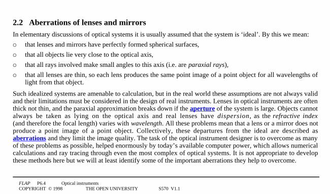
2.2 Aberrations of lenses and mirrorsIn elementary discussions of optical systems it is usually assumed that the system is ‘ideal’. By this we mean:
o that lenses and mirrors have perfectly formed spherical surfaces,
o that all objects lie very close to the optical axis,
o that all rays involved make small angles to this axis (i.e. are paraxial rays),
o that all lenses are thin, so each lens produces the same point image of a point object for all wavelengths oflight from that object.
Such idealized systems are amenable to calculation, but in the real world these assumptions are not always validand their limitations must be considered in the design of real instruments. Lenses in optical instruments are oftenthick not thin, and the paraxial approximation breaks down if the aperture of the system is large. Objects cannotalways be taken as lying on the optical axis and real lenses have dispersion, as the refractive index(and therefore the focal length) varies with wavelength. All these problems mean that a lens or a mirror does notproduce a point image of a point object. Collectively, these departures from the ideal are described asaberrations and they limit the image quality. The task of the optical instrument designer is to overcome as manyof these problems as possible, helped enormously by today’s available computer power, which allows numericalcalculations and ray tracing through even the most complex of optical systems. It is not appropriate to developthese methods here but we will at least identify some of the important aberrations they help to overcome.

FLAP P6.4 Optical instrumentsCOPYRIGHT © 1998 THE OPEN UNIVERSITY S570 V1.1
Spherical aberration
A conventional lens, with spherical surfaces, causes parallel rays which pass through the outer parts of the lensto cross the optical axis at points closer to the lens than rays through the central parts of the lens1—1the focallength of the lens increases smoothly as the rays get closer to the optical axis. This causes a point-like object tohave an image that is not point-like1—1an effect known as spherical aberration. ☞

FLAP P6.4 Optical instrumentsCOPYRIGHT © 1998 THE OPEN UNIVERSITY S570 V1.1
F
the caustic curve
cross-section
Figure 23A lens displaying spherical aberration.
As Figure 2 indicates, parallelrays travelling close to theoptical axis of a converging lenswill come to a focus at a point F,but due to spherical aberrationrays at greater distances fromthe axis will meet at points otherthan F, if they meet at all. Infact, after refraction, all suchrays are tangential to a roughlyconical surface, a longitudinalcross section of which is calleda caustic curve. ☞ A screenplaced at right angles to theoptical axis, at a point closer tothe lens than the paraxial focusF, will show a disc of light,representing a transverse crosssection of this conical focalregion.

FLAP P6.4 Optical instrumentsCOPYRIGHT © 1998 THE OPEN UNIVERSITY S570 V1.1
The diameter of the disc will depend on the precise location of the screen, but there will generally be some pointat which the diameter of the disc is minimized. This minimum diameter image represents the least (spherically)aberrated image of a point object on the optical axis and is called the circle of least confusion. It is alwaysfound closer to the lens than the paraxial focus F.
Spherical aberration may be removed by grinding a lens so that it has aspheric surfaces (i.e. not spherical).Such aspheric lenses used to be both expensive and relatively difficult to make, but computer-controlledgrinding and polishing machinery now makes this much easier.

FLAP P6.4 Optical instrumentsCOPYRIGHT © 1998 THE OPEN UNIVERSITY S570 V1.1
rays brought to a focus at the same point
parallel rays(a)
Figure 3a3An idealized lens made up from a series of prisms
Another approach is to assemble the lens from aset of prisms (Figure 3a), whose angles are chosento give the correct deviation for any axial ray andso produce a common focus. This system is bulkyand expensive.

FLAP P6.4 Optical instrumentsCOPYRIGHT © 1998 THE OPEN UNIVERSITY S570 V1.1
a Fresnel lens uses this idea to produce a thin, flat lens
(b)
Figure 3b Section through a Fresnel lens.
A similar but simpler solution is to use large flatplastic lenses, called Fresnel lenses. ☞These have a series of stepped sections on theirsurface which act like a set of prisms, bending thelight towards a common focal point. They areparticularly useful where large apertures arerequired.

FLAP P6.4 Optical instrumentsCOPYRIGHT © 1998 THE OPEN UNIVERSITY S570 V1.1
A frequently used method of reducing spherical aberration, using only spherical surfaces, is to divide thedeviation of rays passing through the lens equally between the two faces of the lens. ☞ This is achieved bygiving the two faces different radii of curvature, so that the lens is asymmetric. This does not eliminate sphericalaberration but lens shapes can be obtained which minimize spherical aberration (Figure 4). The curvaturesrequired depend on the object distance for which they are to be used. The most generally effective lens shape isvery nearly planoconvex. This same principle leads to spectacle lenses having a meniscus shape. Here, when theeyes are looking to one side, the angled pencil of rays which enter the eyes will still be nearly normal to the lenssurfaces.
an asymmetric converging lens
a plano-convex converging lens
a meniscus converging lens
a meniscus diverging lens
Figure 43Varying the curvature of opposite faces of a lens.

FLAP P6.4 Optical instrumentsCOPYRIGHT © 1998 THE OPEN UNIVERSITY S570 V1.1
F
A
B
A'
B'
(a)(b)
Figure 53The effect of stopping down a lens to reduce sphericalaberration. The circles of least confusion (a) from reduced aperturerays A and A′, (b) from almost full-aperture rays B and B′.
One simple way of reducing spherical aberrationis to reduce the lens aperture, allowing onlythose rays which pass near the centre of the lensto contribute to the image (Figure 5). This willproduce a less bright image and ultimately, if theaperture is made very small, diffraction effects(such as those discussed in the next subsection)may also become a problem. The process ofreducing the size of an aperture is known asstopping down a lens.

FLAP P6.4 Optical instrumentsCOPYRIGHT © 1998 THE OPEN UNIVERSITY S570 V1.1
F C
(a)
Figure 6a3Spherical aberration for a concave sphericalmirror. For a concave spherical mirror the focal point for raysnear the axis is half way between the centre of curvature andthe mirror. Rays at the periphery are brought to a focus nearerthe mirror.
Spherical aberration also occurs in reflection from aspherical mirror, as is shown in Figure 6a.

FLAP P6.4 Optical instrumentsCOPYRIGHT © 1998 THE OPEN UNIVERSITY S570 V1.1
Figure 73Sphericalaberration producing acaustic curve by reflectionfrom the inside of a cup oftea.
You may have seen this effect produced by a cup of tea or coffee in brightsunlight. The parallel rays of sunlight are reflected across the surface of the drink(Figure 7), producing a ‘V’-shaped caustic curve, rather than a single focus. Youmay notice that the point of this ‘V’ is at the focal point for paraxial rays, half-waybetween the wall of the cup and the centre of curvature; rays which are furtherfrom the axis turn through smaller angles than do central rays.

FLAP P6.4 Optical instrumentsCOPYRIGHT © 1998 THE OPEN UNIVERSITY S570 V1.1
(b)
Figure 6b3Spherical aberration for a concave parabolicreflector. For a parabolic reflector, all the rays meet at thefocus, just like a satellite dish.
If the reflecting surface is parabolical (i.e. ofparabolic cross section, as in Figure 6b) there isno spherical aberration and all incoming parallelrays come to the same focal point. ☞
This constitutes a major advantage of paraboloidalreflectors and is used to good effect in reflectingtelescopes and in satellite dishes.

FLAP P6.4 Optical instrumentsCOPYRIGHT © 1998 THE OPEN UNIVERSITY S570 V1.1
light from the middle of the lens concentrated here
light from outer region of lens spreads out here
Y
X
Replace with lens of this shapeparallel rays
Figure 83Diagram showing how coma is produced, and the lensshape to reduce it.
ComaA second source of aberration appears when therays are non-axial. ☞ This is due to anasymmetric deviation of non-axial rays bydifferent parts of the lens, bringing them to afocus at different points, as shown in Figure 8.This aberration is called coma and its effectcauses the straight edges of the image to becurved. If the object is bright, then little flaresof light, looking like comet’s tails, may be seenpointing away from the axis. In Figure 8, onlythose rays passing through the central region ofthe lens reach Y to produce a concentrated spotof light. Light from the outer regions of the lensis spread out in the vicinity of X. In this waythe light from a point object will give a smallbright spot with a characteristic comet’s tail.

FLAP P6.4 Optical instrumentsCOPYRIGHT © 1998 THE OPEN UNIVERSITY S570 V1.1
light from the middle of the lens concentrated here
light from outer region of lens spreads out here
Y
X
Replace with lens of this shapeparallel rays
Figure 83Diagram showing how coma is produced, and the lensshape to reduce it.
Coma can be reduced by changing the shape ofthe lens. Fortunately, the shape required toproduce minimum spherical aberration is verynearly the same as that required for zero coma.It is therefore possible to produce individuallenses which display no coma and littlespherical aberration1—1such lenses are verynearly planoconvex (see Figure 8).

FLAP P6.4 Optical instrumentsCOPYRIGHT © 1998 THE OPEN UNIVERSITY S570 V1.1
Chromatic aberration
The third major source of aberration in lenses is caused by the refractive index of a material varying withwavelength (the process called dispersion). Both the refraction produced by a lens and its focal length willtherefore depend on the wavelength and as light passes through the lens the various colours will be separatedand imaged differently. This is called chromatic aberration, ☞ and it produces coloured fringing around theimage.
Question T2
On passing through a prism, violet light is refracted through a greater angle than red light. For which colour oflight does the glass have the lowest refractive index? What does this tell you about the respective speeds of redand violet light in passing through glass?4❏

FLAP P6.4 Optical instrumentsCOPYRIGHT © 1998 THE OPEN UNIVERSITY S570 V1.1
V RI B G Y O
white light
(a)
Figure 9a3Chromatic aberration: dispersion by the lens results indifferent focal lengths for the different wavelengths present in whitelight, with the letters representing the colours of the rainbow (Istands for indigo)
The lens maker’s equation (Cartesian version)for a lens made from glass of refractive index µwith surfaces of radii of curvature r1 and r2,gives the focal length f as:lens maker’s equation
1f
= µ − 1( ) 1r1
− 1r2
(4) ☞
Usually µ decreases with increasingwavelength and so a lens will have a shorterfocal length for shorter wavelengths, withviolet light being brought to a focus nearer thelens than red light, as shown in Figure 9a.

FLAP P6.4 Optical instrumentsCOPYRIGHT © 1998 THE OPEN UNIVERSITY S570 V1.1
FR
FV
object
violetimage
redimage
transversechromaticaberration
longitudinal chromatic aberration
(b)
Figure 9b3Chromatic aberration: separate images are formed for each wavelength.
The different colouredimages will thus havedifferent sizes (Figure9b) and when theyoverlap on a screen theresult is an image withcoloured fringes.
FLAP P6.4 Optical instrumentsCOPYRIGHT © 1998 THE OPEN UNIVERSITY S570 V1.1
low dispersive power
converginglens crown glass
diverging lens flint glass
high dispersive power
Canada balsam
Figure 103An achromatic doublet.
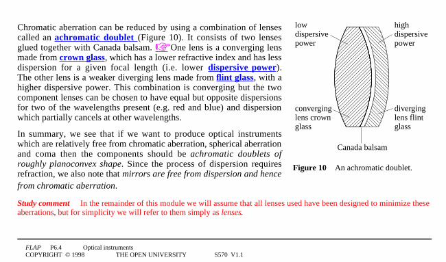
Chromatic aberration can be reduced by using a combination of lensescalled an achromatic doublet (Figure 10). It consists of two lensesglued together with Canada balsam. ☞ One lens is a converging lensmade from crown glass, which has a lower refractive index and has lessdispersion for a given focal length (i.e. lower dispersive power).The other lens is a weaker diverging lens made from flint glass, with ahigher dispersive power. This combination is converging but the twocomponent lenses can be chosen to have equal but opposite dispersionsfor two of the wavelengths present (e.g. red and blue) and dispersionwhich partially cancels at other wavelengths.
In summary, we see that if we want to produce optical instrumentswhich are relatively free from chromatic aberration, spherical aberrationand coma then the components should be achromatic doublets ofroughly planoconvex shape. Since the process of dispersion requiresrefraction, we also note that mirrors are free from dispersion and hencefrom chromatic aberration.
Study comment In the remainder of this module we will assume that all lenses used have been designed to minimize theseaberrations, but for simplicity we will refer to them simply as lenses.

FLAP P6.4 Optical instrumentsCOPYRIGHT © 1998 THE OPEN UNIVERSITY S570 V1.1
2.3 Resolution and angular resolving power: the Rayleigh criterionAnother important limitation on the performance of lenses and mirrors arises from the wave nature of light.The passage of light is governed by the general principles of wave propagation and diffraction theory.Geometrical optics, using rays and straight line propagation, ignores these diffraction effects. When light passesthrough a lens or is reflected from a mirror, the boundary of the lens or the mirror restricts the wavefront and soacts as an aperture. Diffraction leads to divergence of light beams and to images which are not point images butrather extend over small regions. The smaller the aperture of any optical system then the more significant is thediffraction; it is particularly important where we are trying to distinguish fine detail of two images which arevery close together, since each image has a minimum size which is set by diffraction. In particular, if two imagesare produced so close together that diffraction causes the two to overlap, then it may be impossible to distinguishthat there are two separate images and we say that the system is unable to resolve the two images. This questionof resolution has two aspects. First, there is a fundamental imaging resolution of the optical system, called itsangular resolving power; this is due to diffraction and is determined by the aperture of the system.Secondly, the detection of the image (e.g. in the eye or on a film) is limited by the minimum area of the detectorwhich will respond to light. We will consider detector resolution later, but first we discuss the angular resolvingpower of an imaging system.

FLAP P6.4 Optical instrumentsCOPYRIGHT © 1998 THE OPEN UNIVERSITY S570 V1.1
D
θ
(a)
Figure 11a3The Airy pattern formed by diffraction of a parallelbeam of light falling on a small circular aperture of diameter d
When light from a point object passes throughan optical system with a finite aperture thepoint image (or circle of least confusion),predicted by geometric optics, is replaced by adiffraction pattern of the aperture.
For a circular aperture this diffraction pattern,which is known as an Airy pattern, h a scircular symmetry and consists of a brightcentral region (the Airy disc), centred wherethe point image would be, and surrounded bybright rings which become fainter withincreasing distance. Figure 11a shows theintensity across such a pattern.

FLAP P6.4 Optical instrumentsCOPYRIGHT © 1998 THE OPEN UNIVERSITY S570 V1.1
Airy’s analysis showed that the first dark ring lay at an angle θ to the axis of the aperture, given by
Airy’s formula θ = 1. 22λd
4☞
where d is the aperture diameter, λ is the wavelength of the light and θ is in radians. For a point object atinfinity, a lens or mirror of focal length f produces an image at its focus, so the radius r of the first dark ring is
r = 1. 22λf
dThe important fact to note about these equations for θ and r is that the larger the aperture of the objective ormirror, the smaller the spread of the Airy pattern and the more well-defined the image. This is as we anticipated,since diffraction increases with the reduction of the aperture.

FLAP P6.4 Optical instrumentsCOPYRIGHT © 1998 THE OPEN UNIVERSITY S570 V1.1
two point sources completely resolved(b)
Figure 11b3The images of two point sources which are completelyresolved
If two closely adjacent images are producedby an optical instrument then each image willbe an Airy pattern and the two images will beeasily resolved if their Airy patterns are wellseparated (Figure 11b). ☞
If the images are sufficiently close that their Airy patterns overlap then the resultant intensity is normally thesimple sum of the two intensity patterns. If the images are not too close the summationintensity will still show acentral dip in intensity between the two central maxima and the two will be resolved. If the two are too closethen there will be no such dip, but just a central maximum, and so they will appear as a single image.

FLAP P6.4 Optical instrumentsCOPYRIGHT © 1998 THE OPEN UNIVERSITY S570 V1.1
two point sources just resolved (Rayleigh criterion)(c)
Figure 11c3The images of two point sourceswhich are just resolved, according to theRayleigh criterion.
Just what constitutes the resolution limit of two images issubjective, so Lord Rayleigh, ☞ working in the last century,proposed an arbitrary but simple criterion for the resolution limit ofthe diffraction patterns of point sources of equal brightness,generated by circular apertures. He said that two such images1—1and therefore their sources1—1could be just resolved if the centralmaximum of one pattern coincided with the first minimum of thesecond (see Figure 11c). This critical condition for resolution isknown as the Rayleigh criterion.

FLAP P6.4 Optical instrumentsCOPYRIGHT © 1998 THE OPEN UNIVERSITY S570 V1.1
Since the central maximum and first minimum of the Airy pattern are separated by an angle θ, this angle is thesmallest resolvable angle between two images and consequently it is also the smallest resolvable angle betweentwo point objects. This angle is known as the angular limit of resolution, or sometimes as theangular resolving power of the optical system concerned.
The angular limit of resolution (or angular resolving power) θ for an optical system of entrance aperturediameter d, for light of wavelength λ is
θ = 1. 22λd
(5)
where the angle θ is in radians provided λ and d are measured in the same units.
Notice that the angular resolving power of any optical instrument is a fundamental limitation of its aperture andis unaffected by any magnification produced. In any magnification the two overlapping Airy patterns will beequally magnified and the resolution unaffected1—1an indistinct image is equally indistinct, however much it ismagnified!
These resolution limits of optical systems, using visible light, apply equally to systems using electromagneticradiation of other wavelengths. ☞

FLAP P6.4 Optical instrumentsCOPYRIGHT © 1998 THE OPEN UNIVERSITY S570 V1.1
Question T3
Compare the angular resolving power of the following imaging instruments (details of the italicized instrumentsare to be covered later). Take the wavelength of light as 5 × 10⁻⁷
1m.(a) the eye with an effective aperture of 0.51cm(b) a pair of binoculars using a typical aperture of the front lenses(c) the Yerkes Observatory optical telescope, with a diameter of roughly 1.01m(d) the Manchester radiotelescope, with a diameter of 76.2 1m0, using microwave radiation of wavelength
221cm4❏

FLAP P6.4 Optical instrumentsCOPYRIGHT © 1998 THE OPEN UNIVERSITY S570 V1.1
(b)
Figure 6b3Spherical aberration for a concaveparabolic reflector. For a parabolic reflector, all therays meet at the focus, just like a satellite dish.
Diffraction also plays a part in the performance of aparabolic reflector. The arguments concerning the diffractionpattern of a circular aperture are not restricted to incomingparallel radiation being brought to a focus; they applyequally to parallel radiation being produced from a pointsource, placed at the focus of a reflector. If we reverse thedirection of light in Figure 6b we have the case of an idealpoint source of radiation located at the focus of a parabolicreflector. Geometrical optics predicts that the reflectedradiation will form a perfectly parallel beam (unlike the caseof a spherical reflector). In practice, diffraction leads to thereflected radiation not being perfectly parallel, but spreadingover a range of angles in accordance with the Airy pattern,with the angular direction of the first minimum with respectto the optical axis being given by Equation 5.
θ = 1. 22λd
(Eqn 5)

FLAP P6.4 Optical instrumentsCOPYRIGHT © 1998 THE OPEN UNIVERSITY S570 V1.1
The difficulty of increasing the angular resolving power of radio telescopes has been solved in a number ofways. The most effective solution is to combine the signals from several radio telescopes separated by greatdistances. In this way it is possible to regard an array of radio telescopes as having an effective diameter ofseveral kilometres. The extreme case is where telescopes in different continents are combined to give aneffective diameter approaching that of the Earth.
Question T4
A satellite in an orbit at 25 0001km from the Earth transmits information by means of microwaves of 101cmwavelength, generated at the focus of a parabolic dish of 31m diameter. Find the angular spread of the centralbeam reflected from the dish and hence find the transverse dimension of the beam when it reaches the Earth.4❏

FLAP P6.4 Optical instrumentsCOPYRIGHT © 1998 THE OPEN UNIVERSITY S570 V1.1
3 The eyeThe eye is the most familiar optical instrument. It is remarkably sensitive and versatile but its limitations must beappreciated in order to understand the need for and the design of other optical instruments. We begin with thestructure of the eye and then consider some of its common shortcomings.
ciliary muscles
cornea
iris
aqueoushumour
pupil
suspensoryligaments
lens
retina
vitreous humour
opticnerve
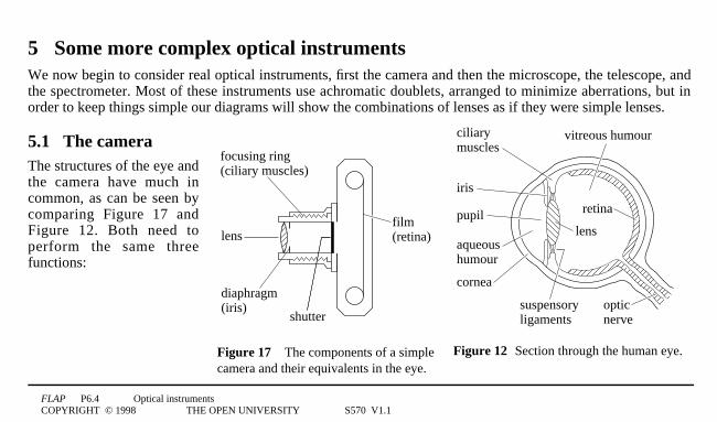
Figure 12 Section through the human eye.
3.1 The structure of the eyeFigure 12 shows a section through the eye. Light enters the eyethrough the transparent cornea, at which refraction first takes place.It then passes through the aqueous humour and, by way of thevariable sized aperture or pupil in the iris (the coloured part of theeye) enters the lens (of the eye), which is held in place bysuspensory ligaments. The focal length of the lens is altered bycontraction or relaxation of the ring-shaped ciliary muscles whichsurround it, allowing the combination of cornea and lens to focus thelight from an object on to the retina. In fact, the cornea produces asubstantial part of the imaging power of the eye. Signals from theretina are relayed to the brain via the optic nerve. Much of the eye isfilled with a clear jelly-like material1—1the vitreous humour.

FLAP P6.4 Optical instrumentsCOPYRIGHT © 1998 THE OPEN UNIVERSITY S570 V1.1
Clear vision requires an optimum amount of light. The eye is dazzled by too much light. With too little light, thedetail is lost, and so too eventually is the colour. The eye automatically controls the light intensity at the imageby changing the size of the pupil. On a bright day the pupil is small, but in the dark it becomes large (dilated).☞The light-sensitive surface of the eye is the retina. This is a thin layer made up of about 125 million cells of twotypes, the rods and the cones. The rods do not respond to the fine detail of the retinal image, but they are verysensitive and provide vision at low light intensities. The cones are found mainly in the central region of theretina, and consist of cells which are sensitive to either red, green or blue wavelengths but they are ineffective atlow light levels.
To establish the performance of the eye try this test for yourself; if you normally wear glasses take them offbefore you begin.
Look out of the window. How far can you see clearly1—1for example, are the leaves on a distant tree sharplydefined or indistinct? When looking at a distant object your eye should feel relaxed because the ciliary musclesare not tightened. When eyes are relaxed, the parallel light rays from a distant object can usually be brought to afocus on the retina. Is this true for your own eyes? The furthest point at which you can see clearly is described asyour far point and for the normal eye this is at infinity.

FLAP P6.4 Optical instrumentsCOPYRIGHT © 1998 THE OPEN UNIVERSITY S570 V1.1
In Subsection 2.1 you saw that the closest distance at which the unaided eye can focus is called theleast distance of distinct vision D and that this position is called the near point. Both the near and far pointscan of course be changed using lenses, as in spectacles, but you may be more surprised to discover that they canalso be changed by reducing the aperture of the eye. Try the following experiment.
Take a piece of card or paper and make a pinhole in it. ☞ Close one eye and look through this pinhole with theother eye. Look first at a distant tree and examine the detail which is now visible. Try this now.
You will probably find that with the distant object much detail is lost1—1for example, if you could distinguishindividual leaves on the tree beforehand, you probably can’t do so through the pinhole. As we saw inSubsection 2.3, the resolution of any optical system, that is its ability to distinguish two nearby objects, islimited by the aperture of the system. This pinhole experiment directly demonstrates the reduction in theresolution of the eye (or visual acuity), when its aperture is dramatically reduced. In the eye there are twoprincipal contributions to this resolution limit. One of these is the angular resolving power of the eye lens itself,which is a diffraction limitation associated with any optical component of finite aperture. The other factorinvolved in this resolution limit is the detector resolution1—1in this case, the finite size of the individual retinalreceptors. Once the image size becomes less than this receptor size, the eye can no longer distinguish any furtherreduction in size.
FLAP P6.4 Optical instrumentsCOPYRIGHT © 1998 THE OPEN UNIVERSITY S570 V1.1
If the images of two nearby small objects are confined to the same retinal receptor then the two objects can nolonger be distinguished. The resolution limit of the normal eye occurs when the two sources are separated byabout 1′ of arc. ☞ We are unable to see detail, or resolve two sources, with angular separations less than this.This angular limit corresponds to a distance of about 0.071mm at the near point.
Question T5
Use the information given above to estimate, for the normal unaided eye: (a) the greatest distance at which theindividual letters on a page can just be distinguished; (b) the size of the smallest object on the Earth which couldjust be seen from the Moon. (See Answer T1).4❏
Now take the pinhole again and look at the effect on the near point by looking through the pinhole at the text onthis page. How close to the text can your eye now come and still be able to focus the text? Try this now.
If you tried this you were probably amazed by the effect on the near point! Instead of being about 251cm it maywell have become about 21cm1—1so close as to be almost at the surface of the eye. You were probably notexpecting to find that a pinhole has a high magnifying power, but the text certainly looks much larger!According to our definition of magnifying power this is true, although the view is rather dim, since very littlelight is admitted.

FLAP P6.4 Optical instrumentsCOPYRIGHT © 1998 THE OPEN UNIVERSITY S570 V1.1
The process by which we gauge the distance to an object involves a complex and subtle interpretative process inthe brain. The size of the image on the retina is determined by the angle subtended by the object at the eye.This in turn depends not only on the distance to the object but also on its size. In depth or distance perception thebrain interprets the information coming from both eyes, along with information coming from the muscularadjustments needed to point both eyes at the object. Our previous experience of the world is also involved in thisinterpretation.

FLAP P6.4 Optical instrumentsCOPYRIGHT © 1998 THE OPEN UNIVERSITY S570 V1.1
rays brought to a focus at the same point
parallel rays(a)
Figure 3a3An idealized lens made up from a series of prisms
Spherical aberration is minimized in the eye’s lensthrough an impressive piece of biologicalevolution.
The refractive index of the lens material is notuniform but decreases away from the centre, sothat the outer regions do not produce excessiverefraction, such as would occur with a simple lens.Figure 3a may help you to understand this, if youconsider the effect that progressively lowerrefractive indices for the prisms would have on thepaths of rays passing through the system. It isinteresting to note that this same technique, ofgrading the refractive index through a material,has recently been re-invented by scientists in fibreoptics technology1☞ —1although for quite adifferent purpose!

FLAP P6.4 Optical instrumentsCOPYRIGHT © 1998 THE OPEN UNIVERSITY S570 V1.1
D
NP
NP
D
D
(a)
(b)
(c)
3.2 Defects of vision: long sight andshort sightFor some people the near point is much furtheraway than 251cm and only more distant objectscan be focused on to the retina.This is called long sight or hypermetropia.The extreme case of this is where theminimum focal length of the eye lens is longerthan the eye cavity; it will then be impossibleto focus a n y object, however distant.Long sight can be corrected using an auxiliaryconverging lens, as is shown in Figure 13.Light coming from an object placed at thenormal near point, D, then appears to comefrom the eye’s own near point, NP, allowing asharp image to be produced.
Figure 133Long sight: (a) an object placed at the normal near point D produces a blurred image on the retina;(b) an object placed at the eye’s near point, NP, forms a sharp image on the retina; (c) the presence of a converging lens causes an object placed at D to appear to be at the eye’s near point.

FLAP P6.4 Optical instrumentsCOPYRIGHT © 1998 THE OPEN UNIVERSITY S570 V1.1
eyeball too long so blurred image formed on retina
FP
FP
(a)
(b)
(c)
rays from eye’s own far point focus on retina
diverging lens
∞
∞
I
For some other people, the far point is muchcloser than infinity and only nearby objectscan be focused on to the retina. This is calledshort sight, or myopia. Because the eyecannot relax sufficiently, the maximum focallength is shorter than the eye cavity andparallel rays cannot be focused at the retina.Short sight can be corrected using anauxiliary diverging lens as shown in Figure14. Parallel rays coming from infinity thenappear to come from the eye’s own far pointFP, allowing a sharp image to be formed.
Short sight: (a) the image position in a myopic eye with an object at infinity;(b) rays from the eye’s far point FP (which is closer than infinity) focus on the retina;(c) a diverging lens makes incoming parallel rays appear to come from the eye’s far point and the short sight is corrected.
Figure 14

FLAP P6.4 Optical instrumentsCOPYRIGHT © 1998 THE OPEN UNIVERSITY S570 V1.1
4 Some simple optical instrumentsIn this section we describe some instruments which use only a single optical component. The simple pinholecould be taken to be the simplest such instrument, since its magnifying power (of around 10) stems from itsability to allow the eye to be brought much nearer to the object than normal. However, the loss of light andresolution mean that the pinhole has very limited usefulness and so we move on to consider the next simplestdevice.

FLAP P6.4 Optical instrumentsCOPYRIGHT © 1998 THE OPEN UNIVERSITY S570 V1.1
θ I
f θ I
parallel lines ∴ image appears at infinity
h
(a)
F
Figure 15a3Ray diagrams for a magnifying glass with: theobject placed at the focal point and the image formed at infinity;It is assumed that the eye is placed very close to the lens so that Dcan be measured from the lens. (The symbol ∴ means ‘therefore’.)
4.1 The magnifying glassA simple magnifying glass consists of a singleconvex lens, with the object placed closer than thefocal point, so that the image is virtual, enlargedand beyond the focal point. If we wish to observethe object with minimum eye strain we arrangethat the eye is fully relaxed (unaccommodated),with the image formed at infinity, rather thanconsciously focused (accommodated). Thisrequires the object to be placed at the first focalpoint F of the convex lens, as shown inFigure 15a.
We see that θ0I ≈ tan1θ0I = h0/f.

FLAP P6.4 Optical instrumentsCOPYRIGHT © 1998 THE OPEN UNIVERSITY S570 V1.1
h'
h
(c)
θ I
D
Final imageformed by optical system
object moved to near point θD
Figure 1c3Magnifying power is the ratio of the anglessubtended (at the eye) by the image and the object whenat the near point.
The magnifying power (given by Equation 3)
Mpower = θI
θD≈ tan θI
tan θD(Eqn 3)
is the ratio of this angle to the angle subtended by theobject when placed at the near point, θD ≈ h0/D, (Figure 1c)and so we have:
Mpower = θI
θD= h
f
D
h
= D
f
The magnifying power is then simply given by the ratio ofthe distance to the near point (251cm) divided by the focallength of the lens. A typical value of f for a simplemagnifier is ~101cm, giving a magnifying power of ~ 2.5.The magnifying power of a magnifying glass with theimage at infinity is equal to the least distance of distinctvision divided by the focal length of the lens
Mpower = D f (6)

FLAP P6.4 Optical instrumentsCOPYRIGHT © 1998 THE OPEN UNIVERSITY S570 V1.1
θ I
u θ I
h
h'
D
(b)
Figure 15b3Ray diagrams for a magnifying glass with theobject brought closer (i.e. between F and the lens) and the imageformed at the near point. It is assumed that the eye is placed veryclose to the lens so that D can be measured from the lens.
If we allow the eye to be accommodated(not fully relaxed) then it is possible to obtain alarger magnifying power than D/f by bringing themagnifying glass closer to the object, so that theobject distance is less than f. The largest sharplyfocused image will then be found when the imageis at the near point, as is shown in Figure 15b.In this case h′/D ≈ θ0I and h0/D ≈ θ0D hence
Mpower = θI
θD= ′h
D
D
h
= ′h
h
We see from Equation 1,
Mtran = ′h
h= v
u(Eqn 1)
that when the image is formed at the near point,the (maximum) magnifying power is the same asthe transverse magnification. ☞

FLAP P6.4 Optical instrumentsCOPYRIGHT © 1998 THE OPEN UNIVERSITY S570 V1.1
Question T6
A magnifying glass of 101cm focal length produces a virtual image 301cm from the lens. Find the position of theobject and hence find the transverse magnification produced by the lens in this arrangement.4❏

FLAP P6.4 Optical instrumentsCOPYRIGHT © 1998 THE OPEN UNIVERSITY S570 V1.1
We can now find an alternative expression for the largest magnifying power of a magnifying glass from thethin lens equation (using the Cartesian sign convention): ☞
1v
− 1u
= 1f
(7)
Multiplying both sides of Equation 7 by v and rearranging it gives us:
vu
= 1 − vf
For maximum Mpower the final image has v = −D, so we have:
Maximum magnifying power of a magnifying glass (when the image is at the near point ):
( Mpower )max = ′h
h= v
u= 1 + D
f(8)
We see that the maximum magnifying power is obtained by adding one to the value of the magnifying powerwith the unaccommodated eye.

FLAP P6.4 Optical instrumentsCOPYRIGHT © 1998 THE OPEN UNIVERSITY S570 V1.1
card with pinhole
screen with both images sharply defined
objects at different distances
Figure 163With a pinhole camera, everything is in focus.
4.2 The pinhole cameraThe pinhole camera is the simplest cameraand functions without the use of any lens, usingthe sharpness of image produced by a smallhole as its basis. ☞ A pinhole camera can bemade, for example, by closing off a tube at oneend with card, making a pinhole in the card andthen forming a transparent screen at the otherend with greaseproof paper. If the pinhole ispointed at a bright source, such as the filamentof a clear electric light bulb, then a sharp imageof the filament is produced on the paper andcan be seen from the back. Figure 16 showsthat the image is a projection of the objectthrough the pinhole1—1each point on the object acts as the source of a single ray, which passes through thepinhole, taken as having negligible size, and arrives at a unique point on the image at the screen. The image sizedepends both on the angular size of the object and on the distance between the pinhole and the screen. Theimage is sharp for any object distance but the illumination is very low, since very little light is admitted.

FLAP P6.4 Optical instrumentsCOPYRIGHT © 1998 THE OPEN UNIVERSITY S570 V1.1
✦ Suppose an attempt were made to admit more light by enlarging the pinhole substantially.
Would this increase the illumination and would there be any other consequences?
To increase the illumination without blurring the image significantly requires the use of a lens, instead of thepinhole. The eye itself is one such example and the photographic camera is another.
FLAP P6.4 Optical instrumentsCOPYRIGHT © 1998 THE OPEN UNIVERSITY S570 V1.1
5 Some more complex optical instrumentsWe now begin to consider real optical instruments, first the camera and then the microscope, the telescope, andthe spectrometer. Most of these instruments use achromatic doublets, arranged to minimize aberrations, but inorder to keep things simple our diagrams will show the combinations of lenses as if they were simple lenses.
focusing ring (ciliary muscles)
lens
diaphragm(iris)
shutter
film(retina)
Figure 173The components of a simplecamera and their equivalents in the eye.
ciliary muscles
cornea
iris
aqueoushumour
pupil
suspensoryligaments
lens
retina
vitreous humour
opticnerve
Figure 12 Section through the human eye.
5.1 The cameraThe structures of the eye andthe camera have much incommon, as can be seen bycomparing Figure 17 andFigure 12. Both need toperform the same threefunctions:

FLAP P6.4 Optical instrumentsCOPYRIGHT © 1998 THE OPEN UNIVERSITY S570 V1.1
o focusing the image on to the photosensitive surface of a detector
o controlling the light intensity of the image
o detecting the light at the image
The camera lens, being made of glass, is not deformable in the same way as the eye lens and so its focal length isfixed. Focusing in the camera is achieved by changing the distance between the lens and the photographic film,which combines the roles of detector and recorder of the image. This film is coated with an emulsion containingsilver compounds. When the emulsion of a black and white film is exposed to light and subsequently developed,small grains of silver are formed, making it darker and resulting in a negative image in which the light areas ofthe object appear as dark areas on the film and vice versa. Photographic films are made with differentsensitivities to light, or with different speeds, with high speed film having the maximum sensitivity. ☞
The total amount of light energy falling on the film (i.e. the exposure) ☞ is controlled in two ways.The shutter speed of the camera governs the time of illumination of the film (i.e. the exposure time) and this isthe principal means used to control the amount of light reaching the film. A second control comes from thevariable aperture or iris diaphragm, which is exactly analogous to the pupil in the iris of the eye.Both these means of controlling the exposure have secondary effects.

FLAP P6.4 Optical instrumentsCOPYRIGHT © 1998 THE OPEN UNIVERSITY S570 V1.1
If the object moves during the exposure time then there will be a range of image positions produced on the film,leading to a blurred photograph. Fast shutter speeds are needed to photograph objects whose angular position ischanging appreciably, such as occurs with rapidly moving objects or with nearby moving objects. The secondaryeffect associated with the iris diaphragm is on the range of object distances which can be simultaneously madesharp in the photograph. This point requires a little more explanation.
With the pinhole camera it was possible to produce an image which was simultaneously sharp for any objectposition. With a lens, this is no longer the case. A particular lens position, focused for a particular objectdistance, will produce an acceptably sharp image over only a limited range of object distances, called thedepth of field of the lens at this focus position. Alternatively, an acceptably sharp image for a particular objectdistance, can be produced over a range of lens positions, called the depth of focus of the lens at this objectposition. ☞ On the basis of the comparison with the pinhole camera, it is not surprising to find that both thedepth of field and the depth of focus increase as the aperture of the lens is reduced. You should appreciate thatthis result has nothing to do with diffraction, but follows from geometrical optics. A given point on the objectacts as a source of several rays, passing through different parts of the lens, with each ray arriving at a slightlydifferent point on the image. As the aperture is reduced, the range of such rays passing through the systemdecreases and so the depth of field and the depth of focus both increase. Diffraction works in the opposite sense;the angular resolving power of a lens decreases as the aperture is reduced, so the visible detail and imagesharpness is downgraded1—1but we need consider this only in the diffraction limit of the performance.

FLAP P6.4 Optical instrumentsCOPYRIGHT © 1998 THE OPEN UNIVERSITY S570 V1.1
In this discussion of depth of field and depth of focus we have used the term ‘acceptably sharp’.This is necessary because the nature of the detector itself presents resolution limits. In the eye, for example, thisis set by the size of the retinal receptors; in the film it is set by the size of the individual silver grains.If the detector resolution were to be increased, for example by using finer grains, then the depth of field and thedepth of focus would change.
✦ If the detector resolution were to be increased, keeping other factors the same, would the depth of fieldincrease or decrease?

FLAP P6.4 Optical instrumentsCOPYRIGHT © 1998 THE OPEN UNIVERSITY S570 V1.1
BB'
B"A
A'A"
aperture
object positions image positions
point image of A perceived as a disc on screen at B
Figure 183The depth of field over which there is no apparent change in image quality. ☞
Figure 18 illustrates how the aperture of a lens controls the depth of field. The extreme rays through the aperturefrom a point object at A are brought to a focus on the detector at B. Due to detector resolution the detector seesthis image as a small disc of light, rather than as a point. If the object is moved to A′ the image moves beyondthe detector to B′ 1—1the disc of light at the detector is now the unfocused image. Similarly, moving the objectaway to A″ produces an image at B″ and again there is a disc of light at the detector. If we choose the positionsA′ and A″ so that the discs of light are the same as the minimum detectable size, then the distance from A′ to A″is the depth of field. Examination of Figure 18 shows that if the lens aperture is reduced, the extreme rays makesmaller angles to the optical axis and the depth of field will be increased: a full analysis shows that the depth offield is inversely proportional to the diameter of the lens aperture.

FLAP P6.4 Optical instrumentsCOPYRIGHT © 1998 THE OPEN UNIVERSITY S570 V1.1
One of the uses of the iris diaphragm of a camera is to change the depth of field deliberately. For example, inlandscape photography a large depth of field is usually desirable so that both near and far objects are in focus,while in portraiture a small depth of field can be used to make the sharply focused sitter stand out from theblurred surroundings.
The effective aperture of a camera lens is usually specified by a quantity known as the f-number.This is obtained by dividing the focal length f of the lens by the diameter of the lens aperture d
i.e. f-number = focal length/aperture diameter = f/d (9)
So for a lens with f = 561mm and d = 201mm, the f-number is 561mm/201mm = 2.8. This is often denoted by f0/2.8.If a lens has an adjustable iris diaphragm then the lens has an adjustable f-number. Normally, lenses areclassified according to their maximum f-number and so for example, we might say that a lens is an f/2.8 lens.If the aperture is very close to the lens then the amount of light passing through the lens is proportional to thearea of the aperture in the diaphragm and therefore to the square of the aperture diameter d. From Equation 9 wesee that for a given focal length, d is inversely proportional to the f-number, so the amount of light admitted isproportional to 1/(f-number)2.
FLAP P6.4 Optical instrumentsCOPYRIGHT © 1998 THE OPEN UNIVERSITY S570 V1.1
As a consequence, the iris diaphragm of a camera usually has a number of predetermined aperture sizes or stopswhich successively halve the area of the aperture; if the aperture were changed by one stop to a higher f-numberthen, for the same exposure, twice the exposure time would be required. The usual f-numbers are 2.8, 4, 5.6, 8,11, 16 and 22. The available exposure times (shutter speeds) therefore also change by factors of about two 1—1typical values (in seconds) are 1, 1/2, 1/4, 1/8, 1/15, 1/30, 1/60, 1/125, 1/250, 1/500, and 1/1000.
Question T7
The light conditions and the film in a camera are such that a good film exposure would be obtained with a shutterspeed of (1/125)1s at f/11. The photographer wishes to photograph a moving object and decides on a shutterspeed of (1/1000)1s. What stop should be used? If the lens has a focal length of 501mm, what is the diameter ofthe aperture at these two stop values?4❏

FLAP P6.4 Optical instrumentsCOPYRIGHT © 1998 THE OPEN UNIVERSITY S570 V1.1
5.2 The compound microscope
The lenses and ray diagram for the compound microscope are shown in Figure 19. The objective (lens) is thelens, or combination of lenses nearest to the object and the eyepiece (lens) is the one nearest to the eye. ☞
θ I
h 1
F e h
h 2
inte
rmed
iate
imag
e
obje
ctiv
e
eypi
ece
obje
ct
fina
l im
age
f e f e f o
D
Figure 193A compoundmicroscope. The objectiveproduces a real, inverted,intermediate image between Feand the eyepiece. This acts asthe object for the eyepiecewhich produces an enlarged,inverted virtual image. If this isat the near point of the eye,then maximum angularmagnification is obtained. Theeye has been shown at a largedistance from the eyepiece, sothat the construction rays maybe included, but in reality theeye is placed at the eyepieceand the final image is at adistance D from the eyepiece.

FLAP P6.4 Optical instrumentsCOPYRIGHT © 1998 THE OPEN UNIVERSITY S570 V1.1
In microscopes (as well as in binoculars and refracting telescopes) it is the function of the objective to gather alarge amount of light from the object and to create a real image. This image is then enlarged by the eyepiece(which may be used in the same way as a simple magnifying glass) to form a virtual image to be seen by the eye.The objective of a microscope is usually of very short focal length, with the focal length of the eyepiece muchlonger; both focal lengths are much shorter than the distance between the lenses.
To find the magnifying power of the microscope, we note that the angle subtended by the image is shown in thediagram as θ0I which, being a small angle, is equal to h2/D. This is assuming that this virtual image is beingformed at the eye’s near point and that the eye is very close to the eyepiece.
FLAP P6.4 Optical instrumentsCOPYRIGHT © 1998 THE OPEN UNIVERSITY S570 V1.1
h'
h
(c)
θ I
D
Final imageformed by optical system
object moved to near point θD
Figure 1c3Magnifying power is the ratio of the anglessubtended (at the eye) by the image and the object whenat the near point.
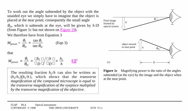
To work out the angle subtended by the object with theunaided eye we simply have to imagine that the object isplaced at the near point; consequently the small angle
θ0D, which it subtends at the eye, will be given by h 0/D(from Figure 1c but not shown on Figure 19).
We therefore have from Equation 3
Mpower = θI
θD≈ tan θI
tan θD(Eqn 3)
that
Mpower = θI
θD= h2
D
h
D
= h2
h☞
The resulting fraction h2/h can also be written as(h2/h1)(h1/h ), which shows that the transversemagnification of the compound microscope is equal tothe transverse magnification of the eyepiece multipliedby the transverse magnification of the objective.

FLAP P6.4 Optical instrumentsCOPYRIGHT © 1998 THE OPEN UNIVERSITY S570 V1.1
✦ A microscope is often used with the final image at infinity. Explain why this is desirable and say where theintermediate image should then be formed.
Question T8
A compound microscope has an objective and an eyepiece separated by a distance of 1801mm and having focallengths of 21mm and 251mm respectively. Where must an object be placed so that the final image, as seenthrough the eyepiece, is formed at infinity?4❏

FLAP P6.4 Optical instrumentsCOPYRIGHT © 1998 THE OPEN UNIVERSITY S570 V1.1
eye lens
field lens
field stop andcrosshairs
Figure 203A lowpower objective.
A typical low power objective (Figure 20) would havea focal length of about 1.51cm, a magnifying power(magnification) of × 10, and would be made up from apair of achromatic doublets, corrected for sphericalaberration and coma.
There are many different designs for compoundeyepieces. In instruments designed primarily formeasurement (as opposed to simple viewing) it is anadvantage to have crosshairs or a graticuleincorporated into the optical system, and their imageshould be in focus at the same place as the imagebeing viewed. The Ramsden eyepiece (see Figure 21)is such an example. It is made up from two lenses; thefield lens and the eye lens.
Figure 213A Ramsden eyepiece showing the position of the field stop and crosshairs.In practice the eye lens would be an achromatic doublet.

FLAP P6.4 Optical instrumentsCOPYRIGHT © 1998 THE OPEN UNIVERSITY S570 V1.1
eye lens
field lens
field stop andcrosshairs
The role of the field lens is to enable the eyepiece to accept rays over a widerange of angles whilst still remaining a relatively small sized component1—1to collect all this light, a single lens eyepiece would have to be large andheavy. An aperture which defines the maximum acceptance angle (and thereforethe maximum field of view) is situated in front of the field lens and is called thefield stop. The intermediate image is formed by the objective in the plane of thefield stop, where the crosshairs are situated. The eyepiece lenses then make therays from the intermediate image parallel before they enter the eye, so that boththe final image and the crosshairs are seen in focus.
Figure 213A Ramsden eyepiece showing the position of the field stop and crosshairs.In practice the eye lens would be an achromatic doublet.

FLAP P6.4 Optical instrumentsCOPYRIGHT © 1998 THE OPEN UNIVERSITY S570 V1.1
Figure 223A planoconvexmicroscope objective. Thepaths of rays in the lens arealmost parallel to the axis.
In microscopes, a large magnification is produced by placing the object very closeto the objective lens and a large amount of light is collected from the object tomake the image clearly visible. ☞ These conditions would generate a lot ofspherical aberration if a symmetrical objective were used. If you examine theexternal face of a microscope objective, it will probably appear flat.For short object distances, a planoconvex lens produces minimum sphericalaberration because ray deviation is divided equally between the surfaces. ☞
By having the plane side facing the incident light (Figure 22) the curved surfacewill then receive rays which are more nearly parallel to the optical axis.The resultant image therefore displays less aberration than it would with asymmetrical objective, since rays distant from the axis will be brought to a focusnearer the focal point.

FLAP P6.4 Optical instrumentsCOPYRIGHT © 1998 THE OPEN UNIVERSITY S570 V1.1
5.3 The refracting telescopeThe simple refracting telescope, making use of two lenses, was one of the first optical instruments to beinvented. The first systematic astronomical observations using such a device were made by Galileo Galilei(1564–1642). He heard that a telescope had appeared in Venice in the spring of 1609 and was able to constructhis own, based on its description, although the previous year there had already been some debate betweenopticians in the Netherlands, including Hans Lippershey (1587–1619), as to who had been the first to develop aninstrument for seeing at a distance. Almost anyone familiar with the magnifying properties of a single lens, andhaving access to two convex lenses for example, would instinctively examine the effect of putting them insuccession and thereby ‘inventing’ a telescope (and/or microscope) of sorts. Telescope design consists of theselection of the lens types to be used.
The main impetus for developing such an instrument was two-fold; as an aid to navigation and trade, theterrestrial telescope was clearly of great value, whilst the greater sophistication it offered in making astronomicalobservations was of considerable importance at a time when debate was raging over new cosmologies.These two areas of application led to the development of two distinct types of telescope:
o The astronomical telescope, in which it is acceptable that the final image may 0be inverted.
o The terrestrial telescope, in which an upright final image is required.

FLAP P6.4 Optical instrumentsCOPYRIGHT © 1998 THE OPEN UNIVERSITY S570 V1.1
eyepiece lensvirtual image at infinity
objective lens
θo θ Ih
Fe, Fo
fefo
Figure 233A simple astronomical telescope. The objective has a long focal length whilstthat of the eyepiece is much shorter.
Both cases view parallellight from a distant objectand so the objective imageis real, diminished andinverted, produced at itsfocal point FO . In thes i m p l e s t f o r m o fastronomical telescope(Figure 23) this objectiveimage is made to coincidewith the focal point Fe ofthe eyepiece, which thenproduces an enlarged,virtual image at infinity,and this is viewed by anobserver’s relaxed eye.The essential differencebetween such a telescopeand a microscope is that in the telescope the intermediate image is produced at the objective’s focus, whereas inthe microscope it is further away.

FLAP P6.4 Optical instrumentsCOPYRIGHT © 1998 THE OPEN UNIVERSITY S570 V1.1
eyepiece lensvirtual image at infinity
objective lens
θo θ Ih
Fe, Fo
fefo
Figure 233A simple astronomical telescope. The objective has a long focal length whilstthat of the eyepiece is much shorter.
It follows that thetransverse magnification ofthe objective is much lessthan 1 for the telescope andgreater than 1 for themicroscope.
Since the object beingviewed by a telescope is atinfinity, the angularmagnification(see Subsection 2.1)is the most appropriatemeasure of the performanceof the instrument.

FLAP P6.4 Optical instrumentsCOPYRIGHT © 1998 THE OPEN UNIVERSITY S570 V1.1
eyepiece lensvirtual image at infinity
objective lens
θo θ Ih
Fe, Fo
fefo
Figure 233A simple astronomical telescope. The objective has a long focal length whilstthat of the eyepiece is much shorter.
From Equation 2
angular magnification
Mang = θI
θO≈ tanθI
tanθO= ′h ′z
h z
(Eqn 2)
and Figure 23 we can seet h a t t h e a n g u l a rmagnification Mang is givenby;
Mang = θ0I0/θO
whereθ0I = h/fe and θΟ = h/fO
i.e. angular magnification of a simple refracting telescope = fO/fe (10)

FLAP P6.4 Optical instrumentsCOPYRIGHT © 1998 THE OPEN UNIVERSITY S570 V1.1
So in order to make Mang as large as possible we need the focal length of the objective to be as long as possibleand the focal length of the eyepiece to be as short as possible. If you have ever looked through a telescope at thenight sky you will have noticed how small an area it covers. This is a direct consequence of the telescope havinga large angular magnification, but it can be very frustrating when trying to find a particular star since it is hard tojudge the relative position of one star to another without reference to the background stars. This is why somehigh power telescopes have a small low power sighting telescope attached to them, to help with initialalignment.
When trying to observe very distant or faint objects we need to collect as much light from them as possible.For this reason the objective lens of a telescope is made as large as possible. Unlike a camera, a telescope doesnot have an iris diaphragm to limit the size of the aperture and it is the objective lens itself which fulfils this roleand therefore acts as the aperture stop.
In general, if we illuminate the aperture stop of an optical system, then its image, formed by any lenses whichprecede it, is called the entrance pupil. For a telescope, the objective is the aperture stop; there are no lensespreceding it and therefore the objective is also the entrance pupil. All rays entering an optical system have topass through the entrance pupil, but the more extreme angled rays passing through the entrance pupil may beunable to travel all the way through the system.

FLAP P6.4 Optical instrumentsCOPYRIGHT © 1998 THE OPEN UNIVERSITY S570 V1.1
fefo
bulb
do de
exit pupil (all rays pass through here)
eyepiece
objective
Fo, Fe
ground-glassscreen
Figure 243Diagram showing formation of the exit pupil in a simple astronomical telescope.The edge of the objective is being used to provide object points which are imaged by the eyepieceand the purpose of the ground-glass screen is to provide uniform illumination of the objective.
The exit pupil issimilarly definedas the image of theaper ture s topformed by alll enses whichf o l l o w it. In atelescope the exitpupil is simply theimage of theobjective formedby the eyepiece,and a ray diagramshowing this isgiven in Figure 24.It is clear from thisfigure, that of allpossible rays entering the objective, those emerging from the telescope must be within the range of rays shown.Also the emerging light is most concentrated at the exit pupil and therefore this is where the eye should beplaced so that the maximum amount of light1—1and therefore information1—1reaches it.

FLAP P6.4 Optical instrumentsCOPYRIGHT © 1998 THE OPEN UNIVERSITY S570 V1.1
fefo
bulb
do de
exit pupil (all rays pass through here)
eyepiece
objective
Fo, Fe
ground-glassscreen
Figure 243Diagram showing formation of the exit pupil in a simple astronomical telescope.The edge of the objective is being used to provide object points which are imaged by the eyepieceand the purpose of the ground-glass screen is to provide uniform illumination of the objective.
From similar triangles in Figure 24;
(dO0/2)/fO = (de0/2)/fe4and therefore4fO0/fe = dO0/de

FLAP P6.4 Optical instrumentsCOPYRIGHT © 1998 THE OPEN UNIVERSITY S570 V1.1
but fO0/fe = Mang4so that4Mang = dO0/de
So the angular magnification of a simple telescope is given by
Mang = objective diameter/exit pupil diameter.
This provides us with a practical method of measuring a telescope’s angular magnification. First we measure thediameter of the objective, then we illuminate the objective, either with a bulb and a ground glass screen ordirectly with a ‘pearl’ bulb, and measure the diameter of the objective’s image formed by the eyepiece on ascreen. We then have the magnification from the ratio of these two diameters.
Question T9
An astronomical telescope has an angular magnification of 40 times. If the diameter of the objective is 121cm andthe length of the tube is 11m calculate the focal length of the objective and the diameter of the exit pupil.4❏

FLAP P6.4 Optical instrumentsCOPYRIGHT © 1998 THE OPEN UNIVERSITY S570 V1.1
A telescope with a wide aperture not only permits the collection of a large amount of light but also has thefurther advantage of a large angular resolving power, as described in Subsection 2.3, enabling the observer todistinguish between sources of light which are close together or see fine detail on the same object. In a telescope,the superimposed diffraction patterns of two close stars produced by the objective would be enlarged by theeyepiece. However, no amount of magnification can improve the resolution of the system. ☞
Perhaps you are now ready to invent a terrestrial telescope!
Question T10
Sketch a ray diagram showing how a third converging lens may be placed between the objective and eyepiece soas to produce an upright final image from a simple refracting telescope.4❏

FLAP P6.4 Optical instrumentsCOPYRIGHT © 1998 THE OPEN UNIVERSITY S570 V1.1
Figure 253Image inversion by Porroprisms as used in some binoculars.
5.4 BinocularsBinoculars consist of an identical pair of terrestrial telescopes, set sideby side at a distance which can be adjusted to the user’s eye separation.Each telescope usually has a compound convex objective and eyepieceand the image inversion which this type of system usually produces, isremoved by introducing erecting prisms between the lenses.The erecting system may consist of a pair of 45°–90°–45° prisms which,when used in the ‘total internal reflection’ mode, shown in Figure 25,are called Porro prisms. They are arranged at right angles to oneanother so that the first prism produces a vertical inversion and thesecond a horizontal inversion. The prisms have the additional advantageof reducing the overall length of the telescopes by ‘folding’ the opticalpath between the lenses.
The presence of the prisms means that the optical axis of an objective is displaced horizontally from that of thecorresponding eyepiece. The prisms can therefore be oriented so that the distance between the objectives isgreater than between the eyepieces and therefore further apart than the eyes, thus giving an enhancedstereoscopic vision. As with all terrestrial telescopes, the separation of objective and eyepiece is adjustable sothat focusing over a range of object distances can be achieved.

FLAP P6.4 Optical instrumentsCOPYRIGHT © 1998 THE OPEN UNIVERSITY S570 V1.1
5.5 The reflecting telescopeThe function of the objective of a refracting telescope is to gather as much as possible of the light emitted fromthe object and to focus it to form the intermediate image. The larger the diameter of the objective, the greater theamount of light it will collect. There are however disadvantages in using large lenses1—1these are(i) the difficulty and cost of producing them, (ii) their great weight, and (iii) the problems of minimizing theirchromatic aberration.
Reflecting telescopes are designed as a relatively lightweight and accurate method of increasing the diameter ofthe entrance pupil in order that brighter and more distinct images can be seen. They also have the advantage ofhaving no chromatic aberration (before the eyepiece), since the light does not have to pass through a dispersivemedium. ☞ As was discussed in Subsection 2.2, spherical aberration can also be avoided by using an asphericsurface.

FLAP P6.4 Optical instrumentsCOPYRIGHT © 1998 THE OPEN UNIVERSITY S570 V1.1
concavemirror
F
eyepiece
(a)
Figure 26a3Comparison between off-axis, Newtonian andCassegrain reflecting telescopes. Off-axis reflector: the mainreflector is turned so that the image is not on the optical axis.
The design problem of a reflecting telescope is thatof observing the image which will be formed on themirror’s optical axis if that axis points at the object.One solution is to turn the mirror so that the imagefalls outside the path of the incoming rays, as inFigure 26a, but this introduces aberrations. ☞
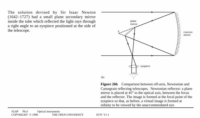
FLAP P6.4 Optical instrumentsCOPYRIGHT © 1998 THE OPEN UNIVERSITY S570 V1.1
concavemirror
eyepiece
F
planemirror
(b)
Figure 26b3Comparison between off-axis, Newtonian andCassegrain reflecting telescopes. Newtonian reflector: a planemirror is placed at 45° to the optical axis, between the focusand the reflector. The image is formed at the focal point of theeyepiece so that, as before, a virtual image is formed atinfinity to be viewed by the unaccommodated eye.
The solution devised by Sir Isaac Newton(1642–1727) had a small plane secondary mirrorinside the tube which reflected the light rays througha right angle to an eyepiece positioned at the side ofthe telescope.

FLAP P6.4 Optical instrumentsCOPYRIGHT © 1998 THE OPEN UNIVERSITY S570 V1.1
concavemirror
F
eyepiece
convexmirror
(c)
Figure 26c3Comparison between off-axis, Newtonian andCassegrain reflecting telescopes. Cassegrain reflector: a convexreflector forms an image which coincides with the focal point of theeyepiece. A virtual image is formed at infinity, to be viewed by theunaccommodated eye.
An alternative system, which maintains axialsymmetry, is the Cassegrain reflector in whichthe light is reflected from a secondary curvedmirror and brought to a focus through a smallhole in the main reflector. ☞

FLAP P6.4 Optical instrumentsCOPYRIGHT © 1998 THE OPEN UNIVERSITY S570 V1.1
5.6 The spectrometerIn the early days of astronomy one of the main tasks was to map the positions and relative brightnesses of thestars. However the light from stars gives us more information than simply position and brightness. By analysingthe distribution of energy with respect to wavelength in the light from stars we can begin to find out much moreabout their relative motions, the elements contained within them and even their origins and ultimate destiny.
The one device which is central to unravelling the information contained within the light from stars is thespectrometer. As its name implies, its primary function is to disperse electromagnetic radiation and measure theintensities of the radiation in the spectra produced1—1its application to astronomy is just one of the many tasksfor which it is employed.
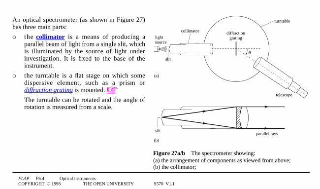
FLAP P6.4 Optical instrumentsCOPYRIGHT © 1998 THE OPEN UNIVERSITY S570 V1.1
lightsource
slit
diffractiongrating
turntable
telescope
(a)
θ
slitparallel rays
(b)
collimator
Figure 27a/b3The spectrometer showing: (a) the arrangement of components as viewed from above;(b) the collimator;
An optical spectrometer (as shown in Figure 27)has three main parts:
o the collimator is a means of producing aparallel beam of light from a single slit, whichis illuminated by the source of light underinvestigation. It is fixed to the base of theinstrument.
o the turntable is a flat stage on which somedispersive element, such as a prism ordiffraction grating is mounted. ☞The turntable can be rotated and the angle ofrotation is measured from a scale.

FLAP P6.4 Optical instrumentsCOPYRIGHT © 1998 THE OPEN UNIVERSITY S570 V1.1
lightsource
slit
diffractiongrating
turntable
telescope
(a)
θ
collimator
eyepiece
crosswires(c)
Figure 27a/c3The spectrometer showing: (a) the arrangement ofcomponents as viewed from above; (c) the telescope.
o t h e telescope1— 1this is able to rotateindependently of the turntable and its relativeposition can be measured by means of avernier against the turntable scale.The eyepiece of the telescope contains a crosswire with which the angular position of aparticular wavelength of light can be found.If the spectrometer were to be used tomeasure intensities as well as positions thenthe telescope eyepiece would be replaced byan optical detector.

FLAP P6.4 Optical instrumentsCOPYRIGHT © 1998 THE OPEN UNIVERSITY S570 V1.1
6 Closing items
6.1 Module summary1 The magnification of an optical system may be described in one (or more) of three ways:
transverse magnification, angular magnification and magnifying power.
44transverse magnification44 Mtran = ′h
h= v
u(1)
44angular magnification4 Mang = θI
θO≈ tanθI
tanθO= ′h ′z
h z(2)
44magnifying power4422 Mpower = θI
θD≈ tan θI
tan θD(3)
2 The spherical aberration of a lens is associated with the reduction in focal length of the outer parts of thelens compared with the central parts. Coma arises when oblique rays focus at different positions from axialrays. Chromatic aberration occurs because dispersion by the lens results in the focal length for violet lightbeing shorter than the focal length for red light.

FLAP P6.4 Optical instrumentsCOPYRIGHT © 1998 THE OPEN UNIVERSITY S570 V1.1
3 Spherical aberration and coma in convex lenses may be much reduced by ‘bending the lens’ to a nearplanoconvex shape. Chromatic aberration is minimized by cementing a high index convex lens to a lowindex concave lens to make a converging achromatic doublet in which the dispersions of the two glassescancel one another.
4 The angular resolving power of any optical system is diffraction limited by its finite aperture. The image ofa point source created by a system with a circular aperture shows this diffraction as a circular Airy pattern.The Rayleigh criterion for the resolution of two adjacent Airy patterns is that the maximum of one patternfalls on the first minimum of the other. The angular resolving power thus increases with the diameter of theaperture. The ultimate limit to resolution is set by the relationship between the size of the entrance apertured and the wavelength λ of the radiation used
44angular resolving power44 θ = 1. 22λd
(5)
5 The simple defects of vision, i.e. long and short sight, are attributed to the inability of the eye lens to focusimages of near and far objects on the retina. Simple lenses enable these defects to be corrected.
6 The magnifying glass creates an enlarged, erect and virtual image of an object placed closer to the lens thanthe focal point.
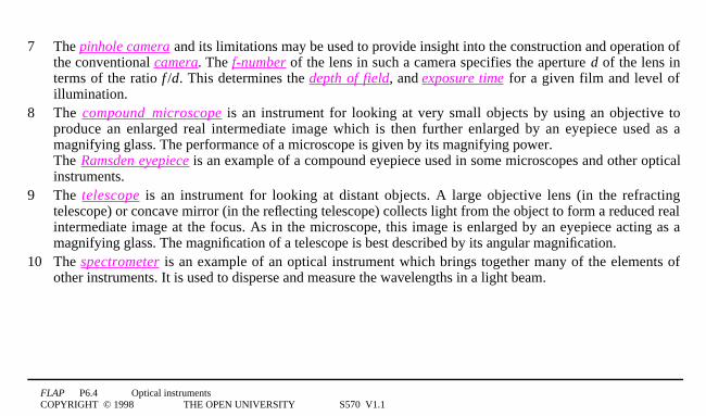
FLAP P6.4 Optical instrumentsCOPYRIGHT © 1998 THE OPEN UNIVERSITY S570 V1.1
7 The pinhole camera and its limitations may be used to provide insight into the construction and operation ofthe conventional camera. The f-number of the lens in such a camera specifies the aperture d of the lens interms of the ratio f0/d. This determines the depth of field, and exposure time for a given film and level ofillumination.
8 The compound microscope is an instrument for looking at very small objects by using an objective toproduce an enlarged real intermediate image which is then further enlarged by an eyepiece used as amagnifying glass. The performance of a microscope is given by its magnifying power. The Ramsden eyepiece is an example of a compound eyepiece used in some microscopes and other opticalinstruments.
9 The telescope is an instrument for looking at distant objects. A large objective lens (in the refractingtelescope) or concave mirror (in the reflecting telescope) collects light from the object to form a reduced realintermediate image at the focus. As in the microscope, this image is enlarged by an eyepiece acting as amagnifying glass. The magnification of a telescope is best described by its angular magnification.
10 The spectrometer is an example of an optical instrument which brings together many of the elements ofother instruments. It is used to disperse and measure the wavelengths in a light beam.

FLAP P6.4 Optical instrumentsCOPYRIGHT © 1998 THE OPEN UNIVERSITY S570 V1.1
6.2 AchievementsHaving completed this module, you should be able to:
A1 Define the terms that are emboldened and flagged in the margins of the module.
A2 Apply the terms transverse magnification, angular magnification and magnifying power appropriately tooptical instruments.
A3 Describe the major lens defects of spherical aberration, coma and chromatic aberration and explain howthey may be reduced.
A4 Describe angular resolving power and the Rayleigh criterion. Calculate angular resolving power, given theaperture and wavelength.
A5 Describe the main structural features of the eye.
A6 Describe the main defects of vision and identify the means used to correct them.
A7 Describe the behaviour of a magnifying glass using ray diagrams.
A8 Describe the operation of the pinhole camera and the conventional lens camera. Interpret and use theterms: depth of field, depth of focus and f-number. Compare the behaviour of the eye and the camera.

FLAP P6.4 Optical instrumentsCOPYRIGHT © 1998 THE OPEN UNIVERSITY S570 V1.1
A9 Describe the arrangement of lenses used in a compound microscope and use this to construct ray diagramsshowing its operation.
A10 Describe the arrangement and operation of a Ramsden eyepiece.
A11 Describe the arrangement of lenses used in astronomical and terrestrial refracting telescopes and draw raydiagrams showing their operation.
A12 Describe the use of erecting prisms in binoculars.
A13 Distinguish between the Newtonian and Cassegrain reflecting telescopes.
A14 Describe the component parts and general operation of a spectrometer.
Study comment You may now wish to take the Exit test for this module which tests these Achievements.If you prefer to study the module further before taking this test then return to the Module contents to review some of thetopics.

FLAP P6.4 Optical instrumentsCOPYRIGHT © 1998 THE OPEN UNIVERSITY S570 V1.1
6.3 Exit test
Study comment Having completed this module, you should be able to answer the following questions each of which testsone or more of the Achievements.
Question E1
(A5 and A8)3Complete Table 1 comparing the eye and the camera.
Table 14For use with Question E1.
Function Eye Camera
light sensitive surface photographic film
ciliary muscles distance setting ring
corrects for sphericalaberration
graded refractive index
cone cells fast film

FLAP P6.4 Optical instrumentsCOPYRIGHT © 1998 THE OPEN UNIVERSITY S570 V1.1
Question E2
(A3 and A6)3Explain why a person with hypermetropia (long sight) needs to wear glasses which haveconverging lenses. Why are these lenses likely to be meniscus shaped? Sketch a diagram which shows howrefraction of parallel rays takes place with a converging meniscus lens.
Question E3
(A2 and A7)3A magnifying glass has a focal length of 101cm. Compare its magnifying powers when used toview images formed at the far point (assumed to be at infinity) and at the near point (taken as 251cm).Assume that the observer’s eye is placed very close to the lens.

FLAP P6.4 Optical instrumentsCOPYRIGHT © 1998 THE OPEN UNIVERSITY S570 V1.1
Question E4
(A2 and A9)3Draw a ray diagram for a compound microscope to show how a virtual image may be formed atthe eye’s near point. Using this diagram describe how the magnifying power is related to the linearmagnification of each of the lenses.
Question E5
(A2 and A11)3The focal lengths of the objective and eyepiece of an astronomical refracting telescope are1001cm and 101cm, respectively. Find (a) the angular magnification of the telescope, and (b) the angle subtendedby the image, seen by an eye very close to the eyepiece, of a building which is 551m high, situated at a distanceof 51km.
FLAP P6.4 Optical instrumentsCOPYRIGHT © 1998 THE OPEN UNIVERSITY S570 V1.1
Question E6
(A4 and A13)3A Newtonian reflecting telescope has an aperture diameter of 251cm. It is being used to observetwo distant point sources which are close together. If the mean wavelength of light from these sources is6 × 100−71m calculate the minimum angular displacement they must have so that they may be clearlydistinguished.
Question E7
(A14)3Describe the component parts and operation of an optical spectrometer.
Study comment This is the final Exit test question. When you have completed the Exit test go back to Subsection 1.2 andtry the Fast track questions if you have not already done so.
If you have completed both the Fast track questions and the Exit test, then you have finished the module and may leave ithere.