flexible multipath transport protocols · 2020-04-14 · flexible multipath transport protocols...
TRANSCRIPT

Flexible Multipath TransportProtocols
Quentin De Coninck
Thesis submitted in partial ful�llment of the requirements for
the Degree of Doctor in Applied Sciences
March 2020
ICTEAMLouvain School of Engineering
Université catholique de LouvainLouvain-la-Neuve
Belgium
Thesis Committee:Pr. Olivier Bonaventure (Advisor) UCLouvain/ICTEAM, BelgiumPr. Ramin Sadre UCLouvain/ICTEAM, BelgiumPr. Benoit Donnet Université de Liège, BelgiumPr. Charles Pecheur (Chair) UCLouvain/ICTEAM, BelgiumPr. Costin Raiciu Universitatea Politehnica din
Bucuresti, Romania

Flexible Multipath Transport Protocolsby Quentin De Coninck
© Quentin De Coninck 2020ICTEAMUniversité catholique de LouvainPlace Sainte-Barbe, 21348 Louvain-la-NeuveBelgium
This work was partially supported by the F.R.S-FNRS.

Simplicity is a great virtue but it requires hard work
to achieve it and education to appreciate it.
— EDSGER W. DIJKSTRA


Preamble
In �fty years, the Internet has drastically altered our everyday lives. In theearly seventies, the ARPANET was the �rst computer network linking hugemainframes between a few American universities. Nowadays, the Internetconnects billions of devices — sometimes smaller than a bank cart — andcauses a constant revolution of our society. From an economical viewpoint,computer networks introduced the age of digital industry. Together, e-com-merce platforms and social networks impact our culture, our economy andour human interactions.
The last ten years have seen a new trend in the Internet: device mobility.In the early 2000s, most of the computers were heavy desktops connectedto the Internet by cable. These devices were intended to remain static on adesk. Now, mobile devices such as smartphones, tablets and connected carsbecome the norm. These devices include several wireless network interfacessuch as Wi-Fi and LTE to keep Internet connectivity when the user moves.This ability to seamlessly switch from one network to another is critical tosupport such mobile use cases.
Unfortunately, the dominant TCP transport protocol [rfc793] does notenable hosts to perform such network handover. It was designed in the sev-enties to work in the ARPANET network. At that time, early computers wereconnected with a single link and communication took place over a single bidi-rectional path. Because TCP uses IP addresses as identi�ers, a connection isbound to them and cannot shift to another network resulting in di�erent IPaddresses. For example, a smartphone losing Wi-Fi connectivity must teardown all the associated TCP connections — hence notifying a network issueto the user — and then recreates new ones over the always available LTEnetwork. In addition to generate user’s frustration, it adds complexity to ap-plications wanting to support such network mobility.
To address thisTCP design issue, MultipathTCP [Rai+12; rfc6824] allowsconnections to seamlessly take advantage of multiple paths. It was designedas a TCP extension to work in the same networks as plain TCP. A Multi-path TCP connection can start using the Wi-Fi network and then continueon the LTE one without the intervention of the application. This solutionattracted interest from industry with several large-scale deployments [Bon13;KT; BS16; CSP17; Tes19].
However, the usage of multiple paths brings its own speci�c concerns.
i

ii Preamble
The �rst one is the selection of the path to use for the next packet to besent. Some applications initiate large bulk transfers and want to aggregatethe available network bandwidths. Other applications instead generate lightnetwork load but require the lowest latency. In addition, smartphone userstypically care about the usage of the cellular network — more expensive andpower hungry than the Wi-Fi one — while others just do not pay attentionto that. How can a multipath transport protocol handle all these requests bydesign?
This thesis contributes to the exploration of the performance of multi-path transport protocols under various scenarios and proposes solutions tolet them adapt to the use case they serve. In particular, the main contribu-tions of this thesis are the following.
� Performing Multipath TCP measurements on smartphone withreal users. Previous works analyzed the performance of MultipathTCP to assess whether it reaches its bandwidth aggregation goal, es-pecially in controlled environments. However, little is known abouthow Multipath TCP behaves on smartphones in the �eld. To �ll thisgap, we perform two measurement campaigns to observe how the twomain Multipath TCP implementations — the Linux kernel one and theiOS one — operate in the smartphone environment.
� Adapting Multipath TCP to the smartphone use case. While ourprevious measurements show that Multipath TCP works in real net-works, they also point out some suboptimal strategies related to themismatch between the bandwidth aggregation tuning of MultipathTCPand the requirement of mobile device applications. Especially, interac-tive applications such as Apple’s Siri need to keep the response latencyas low as possible, even in mobile situations, while meeting the user’sexpectations of using the Wi-Fi network when available. For this, weconsider such request/response network tra�c, adapt Multipath TCPto this use case and evaluate it with Android 6 smartphones.
� Designing Multipath extensions for the QUIC protocol. Both in-network middleboxes and TCP design issues a�ect the �exibility ofMultipath TCP. These hinder the deployment of innovations at thetransport layer. To get rid of them, we consider the QUIC proto-col whose speci�cation is being �nalized within the IETF. Thanks toits near-fully encrypted and authenticated UDP-based packets and itsclean design, it makes it easy to develop new extensions without expe-riencing network interference. Based on our experience with MultipathTCP, we design Multipath extensions for the QUIC protocol and eval-uate them in a broad range of emulated and real networks.

Preamble iii
� Revisiting protocol extensibilitywith plugins. Protocol extensionsare negotiated during the connection handshake. While this determinesif an extension can be used over a given exchange, it does not solve itsdeployment. TCP extensions — including Multipath TCP— typicallysu�er from the chicken-and-egg issue where both the client and theserver wait for its peer to support it �rst. QUIC o�ers us an opportu-nity to reconsider the whole design of transport protocols. Instead ofproposing black-box transport protocol implementations, we proposea gray-box approach where an implementation exposes an API o�er-ing protocol operations. This API can be modi�ed or even extended byprotocol plugins exchanged over an encrypted QUIC connection. Wedesign such a pluginizable protocol and demonstrate that we can pro-vide a plugin o�ering multipath capabilities adapted to a speci�c usecase.
The remaining of this thesis is organized as follows. We �rst introduce inChapter 1 the background related to Multipath TCP. Chapter 2 then describesour two Multipath TCP measurement campaigns on smartphones. Based onthe lessons learned, we present in Chapter 3 an adapted version of MultipathTCP tuned for interactive applications on smartphones. This work particu-larly motivates the need for higher �exibility at the transport layer. For this,we consider the QUIC protocol described in Chapter 4. First, Chapter 5 pro-poses and evaluates a Multipath design for an early version of QUIC. We thenreconsider in Chapter 6 how these Multipath extensions can be adapted to thecurrent version of QUIC and compare its bene�ts to the early design. Next,Chapter 7 presents Pluginized QUIC, a truly extensible transport protocol al-lowing bytecode injection inside its implementations, and demonstrates itsgeneric approach by implementing the Multipath extensions for the QUICprotocol using only plugins. Finally, we conclude this thesis and discuss fu-ture research directions in Chapter 8.

iv Preamble
Bibliographic notes
Conference Publications
1. Q. De Coninck, M. Baerts, B. Hesmans, and O. Bonaventure. “A FirstAnalysis of Multipath TCP on Smartphones”. In: Passive and Active
Measurement – PAM’16. Springer International Publishing, April 2016,pp. 57–69. isbn: 978-3-319-30504-2. doi: 10.1007/978-3-319-30505-9_5.
2. Q. De Coninck and O. Bonaventure. “Multipath QUIC: Design and Eval-uation”. In: Proceedings of the 13th International Conference on emerg-
ing Networking EXperiments and Technologies - CoNEXT ’17. Incheon,Republic of Korea: ACM Press, December 2017, pp. 160–166. isbn: 978-1-4503-5422-6. doi: 10.1145/3143361.3143370.
3. Q. De Coninck and O. Bonaventure. “Tuning Multipath TCP for Inter-active Applications on Smartphones”. In: Proceedings of the 17th IFIP
Networking Conference and Workshops – IFIP Networking’18. May 2018,pp. 1–9. doi: 10.23919/IFIPNetworking.2018.8696520.
4. V.-H. Tran, H. Tazaki, Q. De Coninck, and O. Bonaventure. “Voice-Activated Applications and Multipath TCP: A Good Match?” In: Pro-ceedings of the 2ndWorkshop onMobile NetworkMeasurement –MNM’18.June 2018, pp. 1–6. doi: 10.23919/TMA.2018.8506489.
5. M. Piraux, Q. De Coninck, and O. Bonaventure. “Observing the Evolu-tion of QUIC Implementations”. In: Proceedings of the Workshop on the
Evolution, Performance, and Interoperability of QUIC – EPIQ’18. ACM,2018, pp. 8–14. doi: 10.1145/3284850.3284852.
6. F. Michel, Q. De Coninck, and O. Bonaventure. “QUIC-FEC: Bring-ing the bene�ts of Forward Erasure Correction to QUIC ”. In: Pro-
ceedings of the 18th IFIP Networking Conference (IFIP Networking) and
Workshops – IFIP Networking’19. IEEE, May 2019. doi: 10.23919/IFIPNetworking.2019.8816838.
7. Q. De Coninck and O. Bonaventure. “MultipathTester: Comparing MP-TCP and MPQUIC in Mobile Environments”. In: Proceedings of the
3rd Workshop on Mobile Network Measurement – MNM’19. June 2019,pp. 221–226. doi: 10.23919/TMA.2019.8784653.
8. Q. De Coninck, F. Michel, M. Piraux, F. Rochet, T. Given-Wilson, A.Legay, O. Pereira, and O. Bonaventure. “Pluginizing QUIC”. In: Pro-ceedings of the ACM Special Interest Group on Data Communication -

Preamble v
SIGCOMM ’19. Beijing, China: ACM Press, 2019, pp. 59–74. isbn: 978-1-4503-5956-6. doi: 10.1145/3341302.3342078.
9. T. Wirtgen, C. Dénos, Q. De Coninck, M. Jadin, and O. Bonaventure.“The Case for Pluginized Routing Protocols”. In: Proceedings of the 27thIEEE International Conference on Network Protocols – ICNP’19. Chicago,Illinois, USA: IEEE, Oct. 2019, p. 12.
Posters
1. Q. De Coninck, M. Baerts, B. Hesmans, and O. Bonaventure. “Poster:Evaluating Android Applications with Multipath TCP”. In: Proceedingsof the 21st Annual International Conference on Mobile Computing and
Networking - MobiCom ’15. Paris, France: ACM Press, 2015, pp. 230–232. isbn: 978-1-4503-3619-2. doi: 10.1145/2789168.2795165.
2. Q. De Coninck, M. Baerts, B. Hesmans, and O. Bonaventure. “A FirstAnalysis of Multipath TCP on Smartphones (Poster Version)”. In: Traf-�c Monitoring and Analysis Workshop – TMA’2016. April 2016.
3. Q. De Coninck and O. Bonaventure. “Observing Network Handoverswith Multipath TCP”. In: Proceedings of the ACM SIGCOMM 2018 Con-
ference on Posters and Demos. ACM, 2018, pp. 54–56.
Journal Publications
1. Q. De Coninck, M. Baerts, B. Hesmans, and O. Bonaventure. “ObservingReal Smartphone Applications over Multipath TCP”. In: IEEE Commu-
nications Magazine 54.3 (Mar. 2016), pp. 88–93. issn: 0163-6804. doi:10.1109/MCOM.2016.7432153.
2. V.-H. Tran, Q. De Coninck, B. Hesmans, R. Sadre, and O. Bonaventure.“Observing real Multipath TCP tra�c”. In: Computer Communications
94 (2016), pp. 114–122. issn: 0140-3664. doi: https://doi.org/10.1016/j.comcom.2016.01.014.
Technical Reports
1. Q. De Coninck and O. Bonaventure. Every Millisecond Counts: Tuning
Multipath TCP for Interactive Applications on Smartphones. Tech. rep.2017. url: http://hdl.handle.net/2078.1/185717.
2. F. Michel, Q. De Coninck, and O. Bonaventure. “Adding forward era-sure correction to quic”. In: arXiv preprint arXiv:1809.04822 (2018).

vi Preamble
3. Q. De Coninck and O. Bonaventure. The Case for Protocol Plugins. Tech.rep. 2019. url: http://hdl.handle.net/2078.1/216493.
IETF Contributions
1. Q. De Coninck and O. Bonaventure. Multipath Extensions for QUIC (MP-
QUIC). Internet-Draft draft-deconinck-quic-multipath-04. Internet En-gineering Task Force, Mar. 2020.
Miscellaneous Contributions
1. M. Piraux, Q. De Coninck, and F. Michel. QUIC Tutorial: Bringing in-
novation back to the transport layer. Invited talk at the Conférenced’informatique en Parallélisme, Architecture et Système – COMPAS’19.Anglet, France, June 2019.
Reproducibility Considerations
Although implementations and measurement scripts are not strictly speakingscienti�c contributions, they contribute to them by showing their feasibilityand their reproducibility. All the software required to run our experimentsare made open-source and can be freely fetched through the listed URLs.
Android measurements (§2.2) http://smartphone.multipath-tcp.org
MultipathTester (§2.3 & §5.3) https://github.com/multipathtester
MultiMob (§3) https://multipath-tcp.org/multimob
Multipath gQUIC (§5) https://multipath-quic.org
PQUIC (§6 & §7) https://pquic.org

Acknowledgments
Although being unoriginal, the �rst person I want to thank is my advisor,Olivier Bonaventure. By proposing me a stimulating master’s thesis, he con-taminated me with the incredible applied research virus and pushed me torealize a Ph.D. thesis. Despite being busy with many side projects, he alwaysfound the time to provide me insightful suggestions and feedback while let-ting me direct my own work. If I achieved all the contributions presented inthis thesis, this is mostly thanks to his support.
I also want to thank all the members of my thesis committee for the timethey spent reading my thesis: Costin Raiciu, Benoit Donnet, Ramin Sadre andCharles Pecheur. We had fruitful discussions during my private defense andI am con�dent their comments will be very valuable for my future works.
While I am the author of this thesis, its content is the result of collabo-rations with other worthwhile people. I �rst acknowledge my master’s the-sis co-author, Matthieu Baerts, without whom I would not have pursued aPh.D. I am also grateful to all my other co-authors: Benjamin Hesmans, Viet-Hoang Tran, Ramin Sadre, François Michel, Maxime Piraux, Florentin Rochet,Thomas Given-Wilson, Axel Legay, Olivier Pereira, Thomas Wirtgen, CyrilDénos and Mathieu Jadin. A special thanks goes to Hajime Tazaki who in-vited me as a lecturer to the IIJ Innovation Institute seminar in Tokyo. Besides,I also want to thank Étienne Rivière for its invitation to present a tutorial atthe COMPAS conference and Laurent Vanbever for having accepted my visitto ETH Zurich.
In addition, I am grateful to the whole IP Networking Lab team and theINGI department. Among them, I want to mention Fabien Duchêne for be-ing an entertaining co-desk colleague, David Lebrun for his short but intensestay in our o�ce, Olivier Tilmans for our fruitful discussions and MathieuJadin for his joyful mood. Special mention to the wonderful QUIC team:François Michel and his CAFEC time, Maxime Piraux for his precise speci-�cation knowledge and Florentin Rochet for his secure point of view. I alsothank all the colleagues with which I shared the o�ce (Raphaël Bauduin, Ben-jamin Hesmans, Viet-Hoang Tran, Thomas Wirtgen,...). I should also includethe whole lunchtime team and all the belote players, but they are too manyto list them (please forgive me). The administrative team must not be for-gotten. In particular, I want to thank our secretary Vanessa Maons (whichis worth more than any other secretary), our accountants (Sophie Renard,
vii

viii Acknowledgments
Steve Arokium, Margaux Hubin,...) and our sysadmin team (Pierre Reinbold,Nicolas Detienne, Anthony Gégo, Ludovic Ta�n,...).
Finally, I want to thank my family and in particular my mother Cathy,my father Vincent and my grand-mother Chantal for their support duringthis long journey. Last but not least, my last thoughts go to Lise. Since thatwinter day, she brings me her merry light in my life and her unfailing support,even in the thoughest times, allowed me to complete this thesis.
Quentin De Coninck9th March, 2020

Contents
Preamble i
Acknowledgments vii
Table of Contents ix
1 Reliable Multipath Transfer 11.1 Addressing Hosts within IP Networks . . . . . . . . . . . . . . 21.2 Enabling Reliable Data Exchange with TCP . . . . . . . . . . . 3
1.2.1 Extending TCP with Options . . . . . . . . . . . . . . 61.2.2 Coping with Middleboxes . . . . . . . . . . . . . . . . 7
1.3 Using Multiple Network Paths with Multipath TCP . . . . . . 81.3.1 Creating a Multipath TCP Connection . . . . . . . . . 91.3.2 Adding Paths to an Existing Multipath TCP Connection 101.3.3 Communicating Additional Addresses to the Peer . . . 131.3.4 Exchanging Data over Multiple Paths . . . . . . . . . . 131.3.5 Multipath-speci�c Algorithms . . . . . . . . . . . . . . 141.3.6 Terminating the Connection . . . . . . . . . . . . . . . 15
2 Evaluating Multipath TCP on Smartphones 172.1 Related Work . . . . . . . . . . . . . . . . . . . . . . . . . . . . 182.2 Analyzing In-The-Wild Android Users . . . . . . . . . . . . . . 19
2.2.1 Enabling Multipath TCP on Android Smartphones . . 192.2.2 Characterization of the Trace . . . . . . . . . . . . . . 212.2.3 Analysis . . . . . . . . . . . . . . . . . . . . . . . . . . 22
2.2.3.1 Creation of the Sub�ows . . . . . . . . . . . 232.2.3.2 Sub�ow Round-Trip-Times . . . . . . . . . . 242.2.3.3 Multipath TCP Acknowledgements . . . . . 252.2.3.4 Utilization of the Sub�ows . . . . . . . . . . 262.2.3.5 Reinjections and Retransmissions . . . . . . 282.2.3.6 Handovers . . . . . . . . . . . . . . . . . . . 29
2.3 Observing the iOS Multipath TCP Implementation . . . . . . . 312.3.1 Design of MultipathTester . . . . . . . . . . . . . . . . 31
2.3.1.1 Test Modes . . . . . . . . . . . . . . . . . . . 312.3.1.2 Measurement Infrastructure . . . . . . . . . 35
ix

x Contents
2.3.1.3 Usage Statistics . . . . . . . . . . . . . . . . 352.3.2 The Interactive iOS Multipath TCP Mode . . . . . . . 362.3.3 Stable Network Runs . . . . . . . . . . . . . . . . . . . 372.3.4 Mobile Experiments . . . . . . . . . . . . . . . . . . . 38
2.3.4.1 Wi-Fi Reachability Distance . . . . . . . . . 382.3.4.2 Multipath TCP and its Interactive Mode . . . 40
2.4 Conclusion . . . . . . . . . . . . . . . . . . . . . . . . . . . . . 44
3 Tuning Multipath TCP for Interactive Applications 453.1 Motivations and Related Works . . . . . . . . . . . . . . . . . 46
3.1.1 LTE State Machine . . . . . . . . . . . . . . . . . . . . 463.1.2 Multipath TCP on Smartphones . . . . . . . . . . . . . 48
3.2 Mimicking Apple’s Siri Tra�c . . . . . . . . . . . . . . . . . . 513.3 Tuning Multipath TCP . . . . . . . . . . . . . . . . . . . . . . 53
3.3.1 Towards Global Packet Scheduling . . . . . . . . . . . 533.3.2 Break-Before-Make Path Management . . . . . . . . . 55
3.3.2.1 Monitoring Connection Status . . . . . . . . 553.3.2.2 Signaling Idle Connections . . . . . . . . . . 57
3.3.3 Immediate Reinjections . . . . . . . . . . . . . . . . . 593.4 Emulation Results . . . . . . . . . . . . . . . . . . . . . . . . . 63
3.4.1 MultiMob Server-Side Packet Scheduler . . . . . . . . 643.4.2 In�uence of the Threshold Values of the Oracle . . . . 653.4.3 In�uence of Oracle Periodicity . . . . . . . . . . . . . 683.4.4 Bulk Download and Primary Sub�ow Loss . . . . . . . 683.4.5 Fast Join Bene�ts . . . . . . . . . . . . . . . . . . . . . 68
3.5 Performance Evaluation . . . . . . . . . . . . . . . . . . . . . . 703.5.1 Micro-Benchmarks . . . . . . . . . . . . . . . . . . . . 71
3.5.1.1 Android Network Handover . . . . . . . . . 713.5.1.2 Mobility Scenarios . . . . . . . . . . . . . . . 72
3.5.2 Measurements with Real Users . . . . . . . . . . . . . 773.6 Limitations . . . . . . . . . . . . . . . . . . . . . . . . . . . . . 793.7 Conclusion . . . . . . . . . . . . . . . . . . . . . . . . . . . . . 80
4 QUIC 834.1 Container Packets and Core Message Frames . . . . . . . . . . 844.2 Establishing a QUIC Connection . . . . . . . . . . . . . . . . . 874.3 Exchanging Data . . . . . . . . . . . . . . . . . . . . . . . . . 884.4 Handling Network Changes with Connection Migration . . . 894.5 Closing the Exchange . . . . . . . . . . . . . . . . . . . . . . . 914.6 Di�erences between iQUIC and gQUIC . . . . . . . . . . . . . 91

Contents xi
5 Multipath gQUIC 955.1 Adding Multipath to gQUIC . . . . . . . . . . . . . . . . . . . 95
5.1.1 Path Identi�cation . . . . . . . . . . . . . . . . . . . . 965.1.2 Reliable Data Transmission . . . . . . . . . . . . . . . 975.1.3 Path Management . . . . . . . . . . . . . . . . . . . . 975.1.4 Packet Scheduling . . . . . . . . . . . . . . . . . . . . 995.1.5 Congestion Control . . . . . . . . . . . . . . . . . . . . 1005.1.6 Summary . . . . . . . . . . . . . . . . . . . . . . . . . 100
5.2 Performance Evaluation of Multipath gQUIC . . . . . . . . . . 1005.2.1 Methodology . . . . . . . . . . . . . . . . . . . . . . . 1015.2.2 Performing Accurate Experiments with Mininet . . . . 1025.2.3 Large File Download . . . . . . . . . . . . . . . . . . . 1035.2.4 Short File Download . . . . . . . . . . . . . . . . . . . 1135.2.5 Network Handover . . . . . . . . . . . . . . . . . . . . 114
5.3 Real Network Comparison using MultipathTester . . . . . . . 1165.3.1 Adapting MultipathTester . . . . . . . . . . . . . . . . 1165.3.2 Stable Network Runs . . . . . . . . . . . . . . . . . . . 1175.3.3 Mobile Experiments . . . . . . . . . . . . . . . . . . . 120
5.4 Related Works . . . . . . . . . . . . . . . . . . . . . . . . . . . 1215.5 Conclusion . . . . . . . . . . . . . . . . . . . . . . . . . . . . . 121
6 Rethinking the Multipath Extensions for iQUIC 1236.1 Design Issues A�ecting Multipath gQUIC . . . . . . . . . . . . 123
6.1.1 Absence of Path Validation . . . . . . . . . . . . . . . 1236.1.2 Correlating Multipath Tra�c . . . . . . . . . . . . . . 1246.1.3 Immutable Symmetric Connection ID . . . . . . . . . . 1246.1.4 Uncontrolled Path Management . . . . . . . . . . . . . 124
6.2 Multipath Extensions for iQUIC . . . . . . . . . . . . . . . . . 1256.2.1 Identifying Unidirectional Flows with Connection IDs 1256.2.2 Proposing Sending Uni�ows to the Peer . . . . . . . . 1266.2.3 Negotiating the Multipath Extensions . . . . . . . . . 1286.2.4 Ensuring Reliable Data Exchange . . . . . . . . . . . . 1286.2.5 Acknowledging the Addresses Used by Uni�ows . . . 1296.2.6 Estimating the Latency of Uni�ows . . . . . . . . . . . 1296.2.7 Impacts on the Multipath-speci�c Algorithms . . . . . 1306.2.8 Summary . . . . . . . . . . . . . . . . . . . . . . . . . 130
6.3 Exploring Asymmetric Network Use Cases . . . . . . . . . . . 1316.4 Making Connections Resilient to the Initial Path Choice . . . . 1336.5 Conclusion . . . . . . . . . . . . . . . . . . . . . . . . . . . . . 136

xii Contents
7 Pluginizing QUIC 1377.1 Local Plugin Insertion . . . . . . . . . . . . . . . . . . . . . . . 139
7.1.1 Pluglet Operating Environment (POE) . . . . . . . . . 1417.1.2 Protocol Operations . . . . . . . . . . . . . . . . . . . 1427.1.3 Attaching Protocol Plugins . . . . . . . . . . . . . . . 1447.1.4 Interacting with Applications . . . . . . . . . . . . . . 1477.1.5 Reusing Plugins across Connections . . . . . . . . . . 147
7.2 Exchanging Plugins . . . . . . . . . . . . . . . . . . . . . . . . 1487.2.1 Distributing Trust . . . . . . . . . . . . . . . . . . . . 1487.2.2 Threat Model and Security Goals . . . . . . . . . . . . 1507.2.3 System Overview . . . . . . . . . . . . . . . . . . . . . 1517.2.4 Exchanging QUIC Plugins . . . . . . . . . . . . . . . . 153
7.3 Exploring Simple Protocol Tuning . . . . . . . . . . . . . . . . 1547.3.1 Tuning ACK Frame Scheduling . . . . . . . . . . . . . 1557.3.2 Restricting the Pacing Rate . . . . . . . . . . . . . . . 1567.3.3 The Cost of Protocol Plugins . . . . . . . . . . . . . . 157
7.4 Building Complete Extensions with Plugins . . . . . . . . . . . 1587.4.1 Making the Implementation Pluginizable . . . . . . . . 1597.4.2 Implementing the Multipath Extensions with Plugins . 1607.4.3 Evaluating the Multipath Plugin . . . . . . . . . . . . . 1647.4.4 Adapting the Multipath Plugin to Interactive Use Cases 1667.4.5 Combining Orthogonal Plugins . . . . . . . . . . . . . 1677.4.6 Plugin Overhead . . . . . . . . . . . . . . . . . . . . . 168
7.5 Validating Plugins . . . . . . . . . . . . . . . . . . . . . . . . . 1717.6 Related Works . . . . . . . . . . . . . . . . . . . . . . . . . . . 1717.7 Discussion . . . . . . . . . . . . . . . . . . . . . . . . . . . . . 1727.8 Conclusion and Future Work . . . . . . . . . . . . . . . . . . . 173
8 Conclusion 175
Bibliography 179

Reliable MultipathTransfer 1In order to grasp the remaining of this thesis, we introduce in this Chapter therelevant networking concepts. Computer networks are composed of layeredprotocols. While the classical OSI model de�nes seven layers, we can simplifyit to �ve layers, each of them relying on the lower layer to provide service tothe upper one. First, the physical layer handles the actual electrical/opticaltransmission between two hosts using a given medium. Second, the data-linklayer relies on the underlying one to de�ne frames exchanged between twodirectly connected hosts. Third, the network layer enables non-directly at-tached hosts to exchange packets between each other thanks to intermediatenodes forwarding them. Fourth, the transport layer de�nes end-to-end com-munications between two hosts and manages their multiplexing. Fifth, theapplication layer consists in the actual data exchange between applicationsrunning on hosts.
From a network viewpoint, this layered architecture leads to the packetstructure described in Figure 1.1. From the transport layer’s perspective, theapplication data constitutes a payload to carry. To perform its operation, thetransport protocol pre�xes this payload with a speci�c header. Then, thenetwork protocol receives the transport segment that forms the payload ofthe network layer. Again, a header is added before the payload to enablethe network protocol to operate on that packet, and so on with the data-linkheader. With such a structure, each layered protocol can process the packet bylooking only at its dedicated header — corresponding to the �rst packet bytes— without performing any operation on the remaining opaque payload.
This thesis focuses on transport layer protocols. To understand on whatthey build, we �rst introduce the IP addressing scheme used by the network
layer (§1.1). Then, we introduce TCP, the most widely used transport protocol
Figure 1.1: The in�uence of the computer network layering on the structureof in-�ight data.
1

2 Chapter 1. Reliable Multipath Transfer
S2
Figure 1.2: An example of IP network containing a client (C), two servers (S1and S2) and six routers (R1 - R6).
(§1.2). Finally, we describe how TCP was extended to support the simultane-ous usage of multiple paths (§1.3).
1.1 Addressing Hosts within IP Networks
Nowadays, Internet Protocol (IP) networks connect billions of devices. Theyprovide addressing schemes such that intermediate routers can forward pack-ets on a best-e�ort manner from a source node to a destination one. Figure 1.2provides an example of such an IP network. Two addressing schemes are cur-rently used: IP version 4 (IPv4) [rfc791] and IP version 6 (IPv6) [rfc2460].
IPv4, designed in the early eighties, supports 32-bit IP addresses. Theirhuman-readable representation follows the format 0.1.2 .3 where 0, 1, 2, 3 ∈[0, 255]. In the provided example, C has two IPv4 addresses — 192.168.1.1 and9.8.7.6 — each assigned to a di�erent interface, while S1 has one bounded toits network interface — 1.2.3.4. IPv4 theoretically provides 232 — about 4 bil-lions — di�erent addresses, which was a comfortable number forty years ago.Yet, there is now no more unallocated addresses in the IPv4 space [ICA11]. Toaddress more than 232 devices with IPv4, a �rst solution is to rely on NetworkAddress Translators (NATs) [rfc3022] to temporarily map an IPv4 addressto another one. A typical example is a Wi-Fi access point providing wirelessconnectivity to a set of devices sharing a pool of private addresses, e.g., from192.168.1.1 to 192.168.1.254. All these devices share the same globally reach-able IPv4 address from the servers’ viewpoint. While allowing network op-erators to adapt IPv4 to the growing Internet without modifying hosts, NATshave two main drawbacks. First, they break the end-to-end principle of theInternet [rfc1958], as the source IP address given by the host behind the NATis not the one observed by the server. Second, NATs complicate the networkmanagement, as a given IP address does not refer to the same host over time.
Another solution to tackle this IPv4 address exhaustion problem is to use

1.2. Enabling Reliable Data Exchange with TCP 3
IPv6. This version extends the address length to 128 bits, enabling the the-oretical support of 2128 devices — about 3.4 × 1038. Their human represen-tation is composed of eight groups of four hexadecimal digits separated bycolons. Picking up our example network in Figure 1.2, C has the IPv6 address2001:0db8:0019:0016:0000:0000:0000:0001. This form often contains a lot ofleading zeros which can be omitted, and consecutive groups of four zeroscan be replaced by the double colon notation (::). Hence, we often write theprevious IPv6 address as 2001:db8:19:16::1.
Hosts can exchange packets if they both have an IP address of the sameversion. For instance, if C wants to transmit a packet on the link to R4 toreach S1, it can send a packet with source IPv4 address 9.8.7.6 and destina-tion one 1.2.3.4. The packet will arrive at R4. It will look at its routing tableto �gure out on which network interface it can reach S1 and then forwardthe packet to the next router. This process repeats on each router until thepacket eventually reaches S1, which then delivers the packet’s payload tothe transport layer. The entries contained in the routers’ forwarding tableare handled by routing protocols such as Open Shortest Path First [rfc2328],Integrated System to Integrated System [rfc1195] and Border Gateway Pro-tocol [rfc4271], although their description is outside the scope of this back-ground. Similarly, if C wishes to communicate with S2, it can generate pack-ets with source IPv6 2001:db8:19:16::1 and destination one 2001:db8:5678::1.
Notice that packets can be exchanged only between two IP addresses ofthe same version, either IPv4 or IPv6. In our example, since C only havean IPv4 address on the link to R4 and S2 is only reachable using IPv6, Ccannot send packets to that destination on the lower link. Still, some networkoperators deployed NAT64 devices [rfc6146] enabling IPv6-only clients toreach IPv4-only servers.
When a device has simultaneously access to several networks, we call itmulti-homed. In our example, C is multi-homed as it can send packets viaeither R1 or R4. In the opposite situation, a device like S2 is single-homed asit has only one network access point. The case of S1 is debatable. We willconsider it to be single-homed, although previous works [Dha+12] show thatthe underlying networks serving either IPv4 or IPv6 are not always the same.
1.2 Enabling Reliable Data Exchange with TCP
IP networks do not guarantee perfect delivery. In particular, packets may belost, corrupted or delivered to the destination in a di�erent order than sent bythe source. To cope with these imperfections, end-hosts typically rely on theTransmission Control Protocol (TCP) [rfc793]. TCP guarantees reliable, in-order bidirectional byte-stream data delivery. Figure 1.3 describes its header.A TCP connection is identi�ed by the 4-tuple (IP src, IP dst, portsrc, postdst).

4 Chapter 1. Reliable Multipath Transfer
0 1 2 3 4 5 6 7 8 9 10 11 12 13 14 15 16 17 18 19 20 21 22 23 24 25 26 27 28 29 30 31
Source Port Destination Port
Sequence Number
Acknowledgment Number
Data
O�setReserved C E U A P R S F Window
Checksum Urgent Pointer
TCP Options
(Length = 4 × (Data O�set − 5))
Figure 1.3: The TCP header [rfc793].
Client Server
SYN(seq num = 1000)
SYN/ACK(seq num = 4000, ack num = 1001)
Connection
Established ACK(seq num = 1001, ack num = 4001)
Connection
Established
DATA...
DATA...
Figure 1.4: Establishing a TCP connection.

1.2. Enabling Reliable Data Exchange with TCP 5
A TCP connection is established as shown in Figure 1.4. A client initiates aconnection by sending a Syn packet, i.e., with the S bit set. This packet alsocontains a randomly chosen sequence number for the client to server data�ow — 1000 in our example. Upon reception of this initial Syn, the serverreplies with a Syn/Ack packet, i.e., both S and A bits are set. It acknowledgesthe Syn packet by setting its acknowledgment number to the initial sequencenumber chosen by the client plus one — 1001 in Figure 1.4. This acknowledg-ment number indicates the next byte the packet’s sender expects to receivenext. In addition, the server also selects a random initial sequence number forthe server to client data �ow — 4000 in our case. Once the client receives theSyn/Ack packet, it replies with an Ack packet — A bit set — acknowledgingit. At this point, the client considers the TCP connection to be established,and can start sending data to the remote host. At the other side, the servermust wait for the Ack packet acknowledging its Syn/Ack one before start-ing sending data over the connection. This connection establishment processis often called the TCP three-way handshake, in reference to the number ofpackets required to establish the exchange.
TCP ensures reliable, in-order byte-stream data delivery thanks to its se-quence and acknowledgment numbers. A receiver delivers data to its upperapplication only if the sequence number of the incoming data packet matchesthe expected acknowledgment one. When it receives a data packet, an hostreplies with an Ack packet with the possibly updated acknowledgment num-ber. However, due to the unreliable nature of the underlying IP networks,packets might be either corrupted, lost or delayed. If a packet faces bit �ipsduring its transmission, the receiver will notice it thanks to the Checksum
�eld and discard the packet, making this equivalent to a loss. In these cases,the receiver will receive data packets which have higher sequence numbersthan the one expected. The data contained in these packets cannot be de-livered to the application yet, as TCP ensures in-order delivery. Instead, thereceiver maintains a bu�er where it keeps all these out-of-order packets. Withsuch system, once the expected sequence number packet arrives, the host candeliver it with all the previously received ones without requiring the retrans-mission of all packets. An end-host advertises the size of the receive bu�er toits peer using the Window �eld.
A sender can detect the loss of TCP packets by two ways. The �rst onerelies on the reception of several duplicate Ack packets, i.e., Ack with thesame acknowledgment number. As an example, consider a situation wherea host sends �ve data packets, and the second one never reaches the peer.The receiver replies to the �rst data packet with an Ack indicating that it isready for the second data packet. Then, it receives the third, the fourth andthe �fth ones, which are not expected. The receiver stores them in its receivebu�er and replies to each of the packets with Ack ones still advertising that

6 Chapter 1. Reliable Multipath Transfer
0 1 2 3 4 5 6 7 8 9 10 11 12 13 14 15
Type Length Value...
Figure 1.5: Format of a TCP option, excluding End-of-options (Type 0) andNo-op (Type 1).
it expects the reception of the second data packet. If all these Acks reach thedata sender, it can infer that the second packet was lost and perform a fastretransmission of this particular packet to quickly recover the data transfer.However, this approach is not su�cient to cope with all loss patterns. Con-sider again our example, but this time the �fth data packet never reaches thereceiver. In such situation, the server will not observe duplicate Ack packets.To cope with such situation, the sender launches a timer when a packet issent. If the packet is not acknowledged before the timer �res, a Retransmis-sion Timeout (RTO) occurs and the sender retransmits the lost packet. Suchretransmission strategies ensure the reliability of TCP transfers.
TCP connections share the common Internet infrastructure, and at somepoint several of them might compete for the same physical link. If their net-work usages exceed the actual capacity, connections will create congestionby �lling router bu�ers. This network pressure increases the experiencedlatency and induces packet losses, involving a decrease of the quality of allexchanges through this bottleneck link. To prevent Internet collapse, TCPincludes congestion control schemes limiting the transmission rate with acongestion window. Many algorithms have been proposed [BP95; rfc2582].The current default one in Linux is CUBIC [HRX08].
A TCP connection can be terminated either gracefully or abruptly. In the�rst case, hosts perform a three-way connection release with Fin (packet withthe F bit set), Fin/Ack andAck packets, similarly to the three-way connectionhandshake. This method ensures that all data sent over the connection areeventually delivered before the exchange e�ectively closes. However, thereare cases where a host wants to directly tear down a connection. To do so, theend point sends to its peer a Rst packet — the R �ag is set. Notice that thisabrupt closing does not ensure the reliable delivery of in-�ight, unacknowl-edged data.
1.2.1 Extending TCP with Options
Extensibility is a key requirement for protocols to adapt to the evolution ofthe Internet. To support extensions, TCP includes the TCP Options �eld inits header, as illustrated in Figure 1.3. Except the End-of-options (Type 0)and No-op (Type 1) options each being one byte long, TCP options followthe Type-Length-Value convention as shown in Figure 1.5. The Length �eld

1.2. Enabling Reliable Data Exchange with TCP 7
indicates the size of the whole option — at least 2 — and Value is a (Length−2)-byte long �eld whose format depends on the Type �eld. Notice that the optionspace is limited to 40 bytes due to the 4-bit encoding of the Data O�set �eld.
The usage of an extension over a speci�c connection is negotiated duringits three-way handshake. The client includes in the Syn packet all the op-tions it wants to use. For its part, the server replies in the Syn/Ack packetwith all the client-provided options it wants to support, i.e., both hosts need toagree to adopt a given extension. Typical Linux hosts include in Syn packetsthe Maximum Segment Size (Type 2, 4 bytes), the Selective Acknowledgment(SACK) Permitted (Type 4, 2 bytes), the Timestamp (Type 8, 10 bytes) andWindow Scale (Type 3, 3 bytes) options. The current length of the TCP Op-
tions �eld in Syn packets is thus 20 bytes (19 bytes plus one padding byte),leaving 20 bytes for future extensions. In the TCP packets that carry data, wemainly see the Timestamp option occupying 12 bytes (10 plus two paddingones). This leaves 28 bytes for options in non-Syn packets, which can beeither used by the SACK option or other extensions.
1.2.2 Coping with Middleboxes
Figure 1.2 presents a simple network with end-hosts generating packets androuters forwarding them. Unfortunately, today’s networks are much morecomplex, containing devices which act neither as end-hosts nor as routers.Computers connected to Wi-Fi networks are often behind a NAT changingboth IPs and ports of a packet. Enterprise networks often contain load bal-ancers to spread the tra�c across servers while relying on �rewalls and in-trusion detection systems to drop suspicious tra�c [She+12]. The cellularnetwork is known to contain both NATs and �rewalls [Wan+11]. We refer tothese middle devices as middleboxes. They form an important part of today’snetworks, being sometimes more numerous than plain routers [She+12].
Previous works [Hon+11; Det+13] show that all the �elds of a packet,including its payload, can be altered by middleboxes. Such network interfer-ence hindered the deployment of some TCP options. For instance, the SACKoption was �rst de�ned in 1996 [rfc2018], although it took about ten yearsbefore being usable on the Internet [Fuk11]. Since some middleboxes rewritethe TCP sequence numbers [Hon+11], they also need to adapt the ones in theSACK options. However, not all these middleboxes were directly behavingwell with the SACK option, and there was a transition period where it wasnot usable. Hence, we need to take these middleboxes into account whendesigning TCP extensions if we want them to be deployed on the Internet.

8 Chapter 1. Reliable Multipath Transfer
1.3 Using Multiple Network Paths with Multipath TCP
Designed in the early eighties, TCP enables a data exchange between hostsover a speci�c 4-tuple (IP src, IP dst, portsrc, postdst) acting as its connectionidenti�er. This implicitly induces that the exchange can only take place overa single network path. Let us return to our example in Figure 1.2. C wants toconnect to 1.2.3.4, pointing to S1. It can start then a connection using the pathto R1 with 192.168.1.1. At some point, C may want to leverage the path to R4with 9.8.7.6 to let the exchange bene�t from the available network resources,e.g., to aggregate bandwidth or to increase network resiliency. However, TCPdoes not allow such resource pooling, as this path would lead to another 4-tuple di�erent from the one of the original connection.
Multipath TCP [rfc6824] aims at solving this issue at the transport layer.Its design goals [Rai+12] are the following.
� Multipath TCP should be able to use several network paths for a singleconnection;
� Multipath TCP should work in all networks where TCP works;
� Multipath TCP should be able to use the network at least as well asregular TCP, but without starving TCP;
� Multipath TCP should be implementable in operating systems withoutusing large memory and processing.
To achieve these goals, Multipath TCP uses the architecture depicted in Fig-ure 1.6. MultipathTCP is designed as aTCP extension relying onTCP options.Applications interact with TCP using the Socket API. The usage of multiplepaths does not change anything from the applications’ viewpoint, enablingthem to use Multipath TCP without requiring any code change. With regularTCP, the Socket API makes the link between the application and its under-lying TCP connection. When using Multipath TCP, the Socket API insteadcommunicates with an additional meta-connection — the Multipath TCP con-nection. This intermediate agent enables the application to keep a single linkwith the Multipath TCP connection, independently of the actual numbers ofTCP paths being used. We often refer to these TCP connections forming theMultipath TCP paths as the TCP subflows of the Multipath TCP connection.The whole management of these TCP subflows is hidden from the application.
From a concrete viewpoint, Multipath TCP relies on TCP options. As wewill see next, Multipath TCP requires several control messages for its op-erations. They all follow the pattern illustrated in Figure 1.7. Notice thatthis format respects the TCP Type-Length-Value one shown in Figure 1.5.The advantage of this speci�c pattern — using the Subtype �eld to identify a

1.3. Using Multiple Network Paths with Multipath TCP 9
Transport Layer
Network Layer
Application Layer
Figure 1.6: High-level architecture ofMultipath TCP, here with a connectionhaving three sub�ows.
0 1 2 3 4 5 6 7 8 9 10 11 12 13 14 15 16 17 18 19
Type = 30 Length Subtype Value...
Figure 1.7: Format of a Multipath TCP option.
Multipath TCP option — is to reserve only one Type value (30) for the wholeMultipath extension, leaving more space for future ones.
The negotiation of the Multipath extension is performed during the TCP3-way handshake, similar to any other TCP extension (§1.3.1). Once bothpeers agree on its usage, they can attach new TCP sub�ows to the Multi-path TCP connection (§1.3.2). Because hosts might not be aware that theirpeer have several addresses — in Figure 1.2 C might not know that S1 hasan IPv6 address — Multipath TCP includes mechanisms to advertise them(§1.3.3). Next, hosts can spread data over their available paths (§1.3.4). Noticethat these multipath operations involve the use of additional algorithms suchas the packet scheduler and the path manager (§1.3.5). Finally, the MultipathTCP connection can be terminated, either gracefully or abruptly (§1.3.6).
1.3.1 Creating a Multipath TCP Connection
To negotiate the usage of multiple paths, Multipath TCP relies on the Mp Ca-pable option (Subtype 0). The Multipath TCP connection establishment isdepicted in Figure 1.8. The client �rst sends a Syn packet with the Mp Capa-ble option containing a 8-byte key KC. If the server supports Multipath TCP,it then replies with a Syn/Ack packet carrying the Mp Capable option alongwith the server’s key KS. Together, these keys serve as a basis to authenti-cate connection’s peers when adding new paths. They also allow each peerto derive a 4-byte token identifying the Multipath TCP exchange. To con�rmthe Multipath TCP connection establishment, the client sends an Ack packet

10 Chapter 1. Reliable Multipath Transfer
Client Server
SYN + Mp Capable (KC)
SYN/ACK + Mp Capable (KS)
Connection
EstablishedACK + Mp Capable (K
C , KS)
Connection
Established
DATA...
DATA...
Figure 1.8: Establishing a Multipath TCP connection.
with Mp Capable containing both KC and KS. Echoing both keys enables theserver to keep minimal state until the connection is fully established.
It may happen that the Multipath negotiation fails. The most commonsituation is when the contacted server does not support it. In such case, itreplies with a Syn/Ack without the Mp Capable option, and the connectionfalls back to regular TCP. Another reason can be middleboxes which removethe Mp Capable option. Again, the host then continues with regular TCP.In any case, the Multipath negotiation failure does not prevent connectivitybetween hosts.
1.3.2 Adding Paths to an Existing Multipath TCP Connection
Once the establishment completed, additional paths can be added to an ex-isting Multipath TCP connection. As illustrated in Figure 1.9, Multipath TCPrequires a four-way handshake before allowing the transmission of data on anew sub�ow. This handshake serves two purposes. First, it creates state onthe endpoints, and possibly on the intermediate middleboxes. Second, boththe client and the server authenticate each other. This authentication is per-formed by using the keys exchanged during the handshake. First, the clientsends a Syn with the Mp Join option illustrated in Figure 1.10. It containsboth the token identifying the connection at server side (TokenS) and a ran-dom value (RC). The server then retrieves the connection associated with thetoken, generates a random value RS and computes the 20-byte long Hash-based Message Authentication Code (HMAC) HMACS as follows
HMACS = HMACKC || KS(RC || RS) (1.1)
where KC and KS are respectively the connection keys of the client and serverthat were exchanged during the Multipath TCP connection handshake. The

1.3. Using Multiple Network Paths with Multipath TCP 11
Client Server
SYN + Mp Join (TokenS , R
C)
Generate RC
Lookup TokenS
Generate RS
Compute HMACS
SYN/ACK + Mp Join (HMACS, RS
)
Verify HMACS
Compute HMACC
ACK + Mp Join (HMACC)
Verify HMACC
ACK
DATA...
DATA...
Figure 1.9: Establishing an additional Multipath TCP sub�ow.
0 1 2 3 4 5 6 7 8 9 10 11 12 13 14 15 16 17 18 19 20 21 22 23 24 25 26 27 28 29 30 31
Kind = 30 Length = 12 ST = 1 Rsv B Address ID
Receiver’s Token
Sender’s Random Number
Figure 1.10: TheMp Join option in the initial Syn.
0 1 2 3 4 5 6 7 8 9 10 11 12 13 14 15 16 17 18 19 20 21 22 23 24 25 26 27 28 29 30 31
Kind = 30 Length = 16 ST = 1 Rsv B Address ID
Sender’s Truncated HMAC
(8 bytes)
Sender’s Random Number
Figure 1.11: TheMp Join option in the Syn/Ack.
12 Chapter 1. Reliable Multipath Transfer
0 1 2 3 4 5 6 7 8 9 10 11 12 13 14 15 16 17 18 19 20 21 22 23 24 25 26 27 28 29 30 31
Kind = 30 Length = 24 ST = 1 Reserved
Sender’s HMAC (20 bytes)
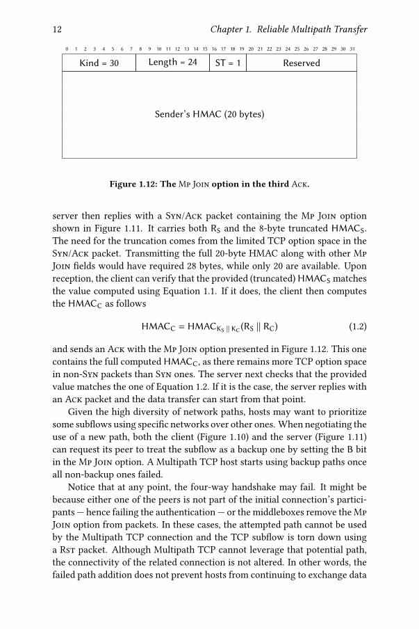
Figure 1.12: TheMp Join option in the third Ack.
server then replies with a Syn/Ack packet containing the Mp Join optionshown in Figure 1.11. It carries both RS and the 8-byte truncated HMACS.The need for the truncation comes from the limited TCP option space in theSyn/Ack packet. Transmitting the full 20-byte HMAC along with other MpJoin �elds would have required 28 bytes, while only 20 are available. Uponreception, the client can verify that the provided (truncated) HMACS matchesthe value computed using Equation 1.1. If it does, the client then computesthe HMACC as follows
HMACC = HMACKS || KC(RS || RC) (1.2)
and sends an Ack with the Mp Join option presented in Figure 1.12. This onecontains the full computed HMACC, as there remains more TCP option spacein non-Syn packets than Syn ones. The server next checks that the providedvalue matches the one of Equation 1.2. If it is the case, the server replies withan Ack packet and the data transfer can start from that point.
Given the high diversity of network paths, hosts may want to prioritizesome sub�ows using speci�c networks over other ones. When negotiating theuse of a new path, both the client (Figure 1.10) and the server (Figure 1.11)can request its peer to treat the sub�ow as a backup one by setting the B bitin the Mp Join option. A Multipath TCP host starts using backup paths onceall non-backup ones failed.
Notice that at any point, the four-way handshake may fail. It might bebecause either one of the peers is not part of the initial connection’s partici-pants — hence failing the authentication — or the middleboxes remove the MpJoin option from packets. In these cases, the attempted path cannot be usedby the Multipath TCP connection and the TCP sub�ow is torn down usinga Rst packet. Although Multipath TCP cannot leverage that potential path,the connectivity of the related connection is not altered. In other words, thefailed path addition does not prevent hosts from continuing to exchange data

1.3. Using Multiple Network Paths with Multipath TCP 13
0 1 2 3 4 5 6 7 8 9 10 11 12 13 14 15 16 17 18 19 20 21 22 23 24 25 26 27 28 29 30 31
Kind = 30 Length ST = 3 IPVer Address ID
Address (IPv4 is 4 bytes, IPv6 is 16 bytes)
Port (optional)
Figure 1.13: The Add Addr option advertising available addresses.
0 1 2 3 4 5 6 7 8 9 10 11 12 13 14 15 16 17 18 19 20 21 22 23 24 25 26 27 28 29 30 31
Kind = 30 Length = 3 + n ST = 4 Reserved n# Address ID
Figure 1.14: The Remove Addr option advertising lost addresses.
over the other paths of the Multipath TCP connection.
1.3.3 Communicating Additional Addresses to the Peer
While a host is aware of all its local addresses, it might not know the ones ofits peer. At the beginning of a connection, the client knows its addresses andthe peer’s one used to contact it. The server might be interested in sharing itsother addresses to establish additional sub�ows over them. To this end, Multi-path TCP provides the Add Addr option shown in Figure 1.13. It supportsboth IPv4 and IPv6 addresses thanks to its IPVer �eld determining the lengthof the Address �eld. Each of these communicated addresses are identi�edby an Address ID. This connection-speci�c identi�er enables referencing theaddress in other options without rewriting it. For instance, the previouslypresented Mp Join option contains the local source Address ID used to createthe new sub�ow. This allows the peer to �gure out if the 2-tuple (IPsrc, portsrc)was altered in transit by, e.g., a NAT.
Similarly, a host can advertise the loss of an address using the RemoveAddr option depicted in Figure 1.14. Note that since lost addresses were pre-viously advertised, hosts can refer to them by using their corresponding Ad-
dress ID. While being useful for path management, these options are not crit-ical for the multipath operations. Therefore, Multipath TCP does not requiretheir reliable delivery, i.e., both sent Add Addr and Remove Addr optionsmay never reach the remote host.
1.3.4 Exchanging Data over Multiple Paths
As it is built atop TCP, Multipath TCP needs to provide reliable, in-order datadelivery. While this service is guaranteed over each TCP path, this does notensure in-order delivery when spreading data over multiple sub�ows. For in-

14 Chapter 1. Reliable Multipath Transfer
0 1 2 3 4 5 6 7 8 9 10 11 12 13 14 15 16 17 18 19 20 21 22 23 24 25 26 27 28 29 30 31
Kind = 30 Length ST = 2 (Reserved) F mM a A
Data ACK (only if A set, 8 bytes if a set else 4 bytes)
Data Sequence Number (only if M set, 8 bytes if m set else 4 bytes)
Subflow Sequence Number (only if M set)
Data-Level Length (only if M set) Checksum (only if M set)
Figure 1.15: The Data Sequence Signal (DSS) option.
stance, if the �rst data A is sent on a slow path and the second one B on a fastsub�ow, the peer will receive B before A. To handle such reordering betweenpaths, an additional sequence number space is required. The Data SequenceSignal (DSS), illustrated in Figure 1.15, provides the Multipath TCP Data Se-
quence Number (DSN) and its corresponding Data ACK. It notably enablesMultipath TCP to retransmit a speci�c piece of data over another sub�ow.Such event is called a reinjection. All Multipath TCP connection packets carryeither the Mp Capable, the Mp Join or the DSS options. Notice that in addi-tion to the Multipath TCP sequence number spaces, the DSS includes threeother �elds (Subflow Sequence Number, Data-Level Length and Checksum)enabling Multipath TCP to cope with possible network interference.
1.3.5 Multipath-speci�c Algorithms
Once the Multipath TCP connection is established, the host has several de-cisions related to multipath to take. They speci�cally cover the creation anddeletion of paths and their usage. The simultaneous use of several paths alsoraises concerns about the fairness against regular TCP.
Path Manager. This component determines when and between which ad-dresses additional sub�ows should be created. The default full-mesh pathmanager in the Linux implementation creates a sub�ow between each pairof compatible addresses as soon as possible. Considering the example in Fig-ure 1.2, there would be 3 sub�ows between C and S1, 2 using IPv4 and 1 usingIPv6. These path creation decisions are only taken by the client, as middle-boxes like NATs usually prevent the server from reaching its peer.
Packet Scheduler. This agent determines on which established sub�ow agiven data packet will be sent. The default packet scheduler in the Linuximplementation selects the lowest estimated latency path whose congestionwindow enables data sending. The Round-Trip-Time (RTT) of a TCP pathcan be estimated by observing the delay between the instant the packet is

1.3. Using Multiple Network Paths with Multipath TCP 15
sent and the moment it is acknowledged, and those observations are thensmoothed [Jac95].
Coupled Congestion Control. Classical TCP congestion controls such asCUBIC aims to share a fair amount of the bottleneck link between compet-ing connections. If a CUBIC Multipath TCP host establishes a lot of sub�owsover this bottleneck link, it will starve other TCP ones. Coupled congestioncontrols, such as LIA [rfc6356; Rai+12] and OLIA [Kha+12], tackle this un-fairness issue by controlling the overall aggressiveness of the multipath con-nection.
1.3.6 Terminating the Connection
Like regular TCP, a Multipath TCP connection can be closed in two ways.First, the graceful Data Fin method consists in setting the F bit of the DSSoption. Once both hosts have advertised and acknowledged the Data Fin, theconnection is closed. This ensures that all in-�ight data is eventually deliv-ered. Second, the abrupt method resides in sending a packet carrying the FastClose option (Subtype 7). In that case, nothing ensures the reliable deliveryof unacknowledged data.
The de�nition of these additional signals enables Multipath TCP to keepthe scope of the Fin and Rst packets at sub�ow level. For instance, a sub�owcan be gracefully or abruptly closed without terminating the related connec-tion itself. This allows Multipath TCP connections to continue their opera-tions while escaping from possibly bad network paths.


Evaluating MultipathTCP on Smartphones 2In the last decade, the Internet has seen the rise of mobile devices such assmartphones, tablets and connected cars. To handle user mobility, these de-vices are typically multi-homed. This means that they can be simultaneouslyattached to several networks. Considering smartphones, they usually haveboth cellular and Wi-Fi connectivity. The multi-homing ability enables mo-bile devices to switch from one wireless network to another one without anyuser intervention.
Currently, TCP is the dominant transport protocol, both on the wired In-ternet and in wireless networks. However, plain TCP connections are boundto their 4-tuple (IPsrc, IPdst, portsrc, portdst). This means that a TCP connectioncannot bene�t from the availability of multiple wireless network accesses.For instance, if a smartphone loses Wi-Fi connectivity, all its previously es-tablished TCP connections using that network interface will be torn down. Insuch mobile situations, the transport protocol does not ensure reliable datadelivery anymore, although Internet connectivity may still be provided overanother available network access.
Multipath TCP [rfc6824; Rai+12] aims at �xing the mismatch betweenthe capabilities of modern devices and TCP limitations. Once standardized in2013, Multipath TCP quickly captured the interest of industry to support var-ious commercial services. In September 2013, Apple realized the �rst large-scale deployment of Multipath TCP to enhance the user experience of theSiri voice recognition application [Bon13] and then extended this multipathcapability to all iOS applications in September 2017. In July 2015, Korean Tele-com (KT) enabled high-end Android devices to use Multipath TCP to aggre-gate both Wi-Fi and cellular networks [KT]. These smartphones can achievedownload rates of over 1 Gbps. Yet, despite these deployments, little is knownabout the actual performance of Multipath TCP on mobile devices.
This Chapter �lls this gap by presenting two di�erent measurement cam-paigns evaluating how well Multipath TCP performs on smartphones. We�rst explore the related works about Multipath TCP measurements (§2.1).Next, we evaluate how Multipath TCP behaves on Android smartphones us-ing the Multipath TCP implementation in the Linux kernel [MPTCPlk] (§2.2).We then test Apple’s Multipath TCP implementation used by the iOS de-
17

18 Chapter 2. Evaluating Multipath TCP on Smartphones
vices [BS16] under speci�c scenarios (§2.3). Finally, we summarize the lessonslearned from our experiments (§2.4).
2.1 Related Work
In this Section, we classify the studies of various researchers that have ana-lyzed the performance of Multipath TCP, and how our work di�ers from theprevious contributions.
Smartphone environment. As shown by Raiciu et al. [Rai+11a], Multi-path TCP achieves its bandwidth aggregation goal in homogeneous wired en-vironments such as data centers. However, the measurements of both Falakiet al. [Fal+10] and Huang et al. [Hua+10] reveal the heterogeneity of wirelessnetworks used by smartphones. They also show that smartphone applicationsgenerate more downlink than uplink tra�c. Unlike in our measurement cam-paigns, these smartphone studies focus on the performance of plain TCP.
Multipath TCP in wireless networks. Chen et al. [Che+13] analyze theperformance of Multipath TCP in Wi-Fi and cellular networks by runningbulk transfer applications on laptops. They �nd that Multipath TCP achievescompletion times comparable to TCP over the fastest network. Chen et al.[CT14] explore the impact of the cellular bu�erbloat when performing bulkdata transfers with Multipath TCP. They also evaluate the impact of applyingthe Opportunistic Retransmission and Penalization algorithm [PKB13]. Fer-lin et al. [FDA14a] con�rm that cellular networks exhibit bu�erbloat whicha�ects the performance of Multipath TCP. Ferlin et al . [FDA14b] propose aprobing technique to detect low performing paths and evaluate it in wirelessnetworks. Deng et al. [Den+14] compare the performance of single-path TCPover WiFi and LTE networks with Multipath TCP on multi-homed devices byusing active measurements and replaying HTTP tra�c observed on mobileapplications. They show that Multipath TCP provides bene�ts for long �owsbut not for short ones, for which the selection of the interface for the initialsub�ow is important from a performance viewpoint. Han et al.[Han+15] an-alyze the behavior of Multipath TCP to load web pages with both HTTP andSPDY. They con�rm that large SPDY �ows are better suited for Multipath TCPthan smaller HTTP ones. Di�erent packet schedulers such as BLEST [Fer+16]and ECF [Lim+17] have been proposed to operate in wireless networks. Still,all these previous works mostly focus on the bandwidth aggregation featureof MultipathTCP under bulk transfers and do not explore network handovers.
Device mobility with Multipath TCP. Raiciu et al. [Rai+11b] �rst dis-cuss how Multipath TCP can be used to support mobile devices either by di-

2.2. Analyzing In-The-Wild Android Users 19
rect client/server connections or through a Multipath TCP proxy. They alsoprovide early measurement results using a laptop. Paasch et al. [Paa+12] thenpropose three distinct path management policies to cope with di�erent wire-less networks. The Full-MPTCP mode creates sub�ows on all pairs of client’sand server’s addresses. These sub�ows are then simultaneously used to ag-gregate the bandwidth of the available networks. The Backup mode also es-tablishes all the sub�ows, but only uses a subgroup. This mode is useful toprioritize some networks over other ones, e.g., to prevent hosts from usingthe cellular interface when Wi-Fi is still available, while keeping fast reactionif primary networks become unavailable. The Single-Path mode is similar tothe Backup one, except that only one sub�ow is established at any time. Thesemodes were included in the Linux implementation of Multipath TCP and theirevaluation on a laptop showed that the network handovers are handled dif-ferently by each mode. Williams et al. [Wil+14] analyze the performance ofMultipath TCP on moving vehicles with bulk transfers. Li et al. [Li+18] mea-sure the performance of Multipath TCP in high-speed trains by leveragingthe availability of multiple cellular networks. Our works continue in thatvein by considering smartphones instead of laptops and by exploring othertra�c patterns than the bulk one.
Other related Multipath TCP works. Hesmans et al. [Hes+15] analyze aone week-long trace collected at the reference server multipath-tcp.org.Compared to our works, they have no control on the devices contained intheir network trace. Saha et al. [Sah+17] extend one of our previous work toevaluate the behavior of Multipath TCP under controlled smartphone appli-cation scenarios. They also explore how Multipath TCP impacts the energyconsumption and CPU usage on such mobile devices.
2.2 Analyzing In-The-Wild Android Users
In this Section, we provide a detailed analysis of a Multipath TCP networktrace generated by smartphones used by real users. We �rst introduce howwe enable smartphones to bene�t from Multipath TCP (§2.2.1). Then, weprovide the basic characteristics of the studied network trace (§2.2.2). Finally,we take a closer look at the performance of Multipath TCP (§2.2.3).
2.2.1 Enabling Multipath TCP on Android Smartphones
Although Multipath TCP is already used by hundreds of millions of Apple’siOS smartphones, Multipath TCP is not yet supported at a large scale on In-ternet servers. Therefore, making the smartphones Multipath TCP capable is

20 Chapter 2. Evaluating Multipath TCP on Smartphones
Figure 2.1: The deployed architecture allowing smartphones to use Multi-path TCP.
not su�cient to generate Multipath TCP tra�c. Indeed, most of the serversdo not recognize the Multipath extension and fallback to plain TCP.
To address this deployment issue, we deployed the infrastructure depictedin Figure 2.1, which is the same architecture as the one used by Korean Tele-com [KT]. As Android relies on the Linux kernel, one can integrate the Linuximplementation of Multipath TCP on our smartphones. In our measurementcampaign, the smartphones run Android 4.4 with a modi�ed Linux kernelthat includes Multipath TCP v0.89.5 [DB]. To force smartphone applicationsto use Multipath TCP, ShadowSocks1 was installed on each smartphone andcon�gured to use a SOCKS server that supports MultipathTCP (v0.89.5) for allTCP connections. The smartphones thus use Multipath TCP over their Wi-Fiand cellular interfaces to reach the SOCKS server. This proxy initiates Multi-path TCP connections to the �nal destinations, but most of them fallback toregular TCP as very few servers on the Internet support Multipath TCP. Us-ing the SOCKS proxy enables us to collect both Wi-Fi and cellular networktra�c using tcpdump without requiring cooperation from an ISP. From theserver side, all the connections from the smartphones appear as coming fromthe SOCKS server. This implies that the external (cellular or Wi-Fi) IP ad-dress of the smartphone is not visible to the contacted servers. This mighta�ect the operation of some servers that adapt their behavior (e.g., the ini-tial congestion window) in function of the client IP address. Moreover, ourShadowSocks client introduces two additional characteristics. First, it sendsDNS requests over TCP. Second, ShadowSocks did not support IPv6 whenwe collected our measurements, so our trace only contains IPv4 packets.
As introduced in §1.3.5, the usage of MultipathTCP involves the operationof several dedicated algorithms. First, the path manager speci�es the strat-egy used to create and delete sub�ows. In our measurements, smartphones
1Available at http://shadowsocks.org.

2.2. Analyzing In-The-Wild Android Users 21
employ the full-mesh path manager that initiates one sub�ow over eachpair of interface addresses as soon as the initial sub�ow has been fully es-tablished or as soon as a new address has been learned. Second, the packet
scheduler [Paa+14] selects, among the active sub�ows having an open con-gestion window, the sub�ow on which the next packet containing data willbe sent. Both the smartphones and the proxy used the default MultipathTCP scheduler that prefers the sub�ow with the smallest RTT. This sched-uler also includes the Opportunistic Retransmission and Penalization (ORP)mechanism [PKB13] aiming at mitigating head-of-line blocking when facingreceive window limitations. Third, the congestion controller de�nes the con-gestion window of each MultipathTCP sub�ow. Here, we rely on the standardLinked Increases Algorithm (LIA) [rfc6356].
Android 4.4 smartphones assume that only one wireless interface is ac-tive at a time. When such a smartphone switches from cellular to Wi-Fi, itautomatically resets all existing TCP connections by using Android speci�cfunctions. To counter this behavior, we installed a special Android applica-tion2 that enables the simultaneous usage of the Wi-Fi and cellular interfaces.It also controls the routing tables and updates the policy routes that are re-quired for Multipath TCP every time the smartphone connects to a wirelessnetwork. Thanks to this application, the modi�ed Nexus 5 can be used by anyuser since it does not require any networking knowledge.
The dataset covers the tra�c produced by a dozen of users using Nexus 5smartphones. These users were either professors, Ph.D. or Master students atUCLouvain. While some of them used their device to go only on the Internet,others were still using them as their main phone after our measurement cam-paign. Measurements were performed in Belgium from March 8th to April28th 2015. Over this period of 7 weeks, more than 71 millions Multipath TCPpackets were collected for a total of 25.4 GBytes over 390,782 Multipath TCPconnections.
2.2.2 Characterization of the Trace
Before going into a more detailed analysis, we �rst look the main character-istics of the Multipath TCP connections in our dataset.
Destination port. Usually, the application level protocol can be identi�edby looking at the destination port of the captured packets. However, as smart-phones connect through a SOCKS proxy, all the packets are sent towards thedestination port used by the proxy, which is 443 in our case to prevent mid-dlebox interference. To �nd the application level protocol, we extract the
2Available at https://github.com/MPTCP-smartphone-thesis/MultipathControl.

22 Chapter 2. Evaluating Multipath TCP on Smartphones
Port # connections % connections Bytes % bytes53 107,012 27.4 17.4 MB < 0.180 103,597 26.5 14,943 MB 58.8443 104,223 26.7 9,253 MB 36.44070 571 0.1 91.7 MB 0.45228 10,602 2.7 27.3 MB 0.18009 10,765 2.8 0.97 MB < 0.1
Others 54,012 13.8 1,090 MB 4.3
Table 2.1: Statistics about destination port fetched by smartphones.
destination port from the SOCKS command sent by the ShadowSocks clientat the beginning of each connection. As shown in Table 2.1, most of the con-nections and data bytes are related to Web tra�c (ports 80 and 443). SinceShadowSocks sends DNS requests over TCP, it is expected to have a largefraction of the connections using port 53. Among other popular port num-bers, there are ports such as 4070 — e.g., used by Spotify —, Google Services(5228) and Google Chromecast (8009).
Duration of the connections. 65% of the observed connections last lessthan 10 seconds. In particular, 4.3% are failed connections, i.e., the �rst Synwas received and answered by the proxy, but the third Ack was lost (or a Rstoccurred). 20.8% of the connections last more than 100 seconds. Six of themlast for more than one entire day (up to nearly two days).
Bytes carried by connections. Most (86.9%) of the connections carry lessthan 10 KBytes. In particular, 3.1% of the connections carry between 9 and11 bytes. Actually, those are empty connections, since the SOCKS commandare 7 bytes long, two bytes are consumed by the Syns and the use of theremaining two bytes depend on how the connections were closed (Rst or Fin).The longest connection in terms of bytes transported around 450 MBytes andwas spread over �ve sub�ows.
2.2.3 Analysis
In the following, the analysis will focus on relevant subsets of the trace such asconnections with at least two sub�ows, connections using at least two sub-�ows or connections experiencing handover. Table 2.2 gives the character-istics of these subsets. They help to analyze how Multipath TCP sub�owsare created (§2.2.3.1), study the heterogeneity of the available networks in

2.2. Analyzing In-The-Wild Android Users 23
Name Description # connections Bytes S→P Bytes P→ST0 Full trace 390 782 652 MB 24 771 MBT1 ≥ 2 established sub�ows 126 040 238 MB 13 496 MBT2 ≥ 2 used sub�ows 32 889 152 MB 11 856 MBT3 With handover 8 461 36.7 MB 4 626 MB
Table 2.2: The di�erent (sub)traces analyzed in this section. S→P: fromsmartphones to proxy. P→S: from proxy to smartphones.
Number of sub�ows 1 2 3 4 5 >5Percentage of connections 67.75% 29.96% 1.07% 0.48% 0.26% 0.48%
Table 2.3: Number of sub�ows per Multipath TCP connection.
terms of round-trip-times (§2.2.3.2), estimate the packet reordering of Multi-path TCP (§2.2.3.3), study how sub�ows are used (§2.2.3.4), quantify the rein-jection overhead (§2.2.3.5) and identify connections experiencing handovers(§2.2.3.6).
2.2.3.1 Creation of the Sub�ows
With Multipath TCP, a smartphone can send data over di�erent paths. Thenumber of sub�ows that a smartphone creates depends on the number ofactive interfaces that it has and on the availability of the wireless networks.
Table 2.3 reports the number of (not necessarily concurrent) sub�ows thatare observed in T0. Most of the connections only have one sub�ow. On an-other side, 2.29% of the connections have more than two sub�ows. Havingmore sub�ows than the number of network interfaces is a sign of mobilityover di�erent Wi-Fi and/or cellular access points since IPv6 was not used. Aconnection establishing 42 di�erent sub�ows was observed.
Another interesting point is the delay between the establishment of theconnection (i.e., the �rst sub�ow) and the establishment of the other sub-�ows. As it relies on the full-mesh path manager, the smartphone triesto create sub�ows shortly after the creation of the Multipath TCP connectionand as soon as a new interface gets an IP address. Late joins can mainly be ex-pected when a smartphone moves from one network access point to another.To quantify this e�ect, Figure 2.2 plots the cumulative distribution function(CDF) of the delays between the creation of each Multipath TCP connectionand all its additional sub�ows that are linked to. 65% of all the additional sub-�ows are established within 200 ms. This percentage increases to 73% if thislimit is set to one second. If the analysis is restricted to the �rst additional

24 Chapter 2. Evaluating Multipath TCP on Smartphones
10−2 10−1 100 101 102 103 104 105 106
Time between MP_ JOIN and MP_CAP [s]
0.0
0.2
0.4
0.6
0.8
1.0C
DF
Additional subflows
Second sublows
104 1060.98
0.99
1.00
Figure 2.2: Delay between the creation of the Multipath TCP connection andthe establishment of a sub�ow.
sub�ow, these percentages are respectively 76% and 86%. Joins can occurmuch after the connection is established. Indeed, 17% of the additional sub-�ows were established one minute after the establishment of the connection,and 2.1% of them were added one hour later. The maximal observed delayis 134,563 seconds (more than 37 hours) and this connection was related tothe Google Services. Those late joins suggest network handovers, and latesecond sub�ow establishments can be explained by smartphones having onlyone network interface available, e.g., switching from a Wi-Fi access point toanother one while having cellular connectivity turned o�.
2.2.3.2 Sub�ow Round-Trip-Times
From now on, we focus on the subtrace T1 that includes all the connectionswith at least two sub�ows. A sub�ow is established using a three-way hand-shake. Thanks to this exchange, the communicating hosts agree on the se-quence numbers and TCP options and also measure the initial value of theround-trip-time for the sub�ow. For the Linux implementation of MultipathTCP, the round-trip-time (RTT) measurement is an important performancemetric because the default packet scheduler prefers the sub�ows havingthe lowest RTTs.
To evaluate the RTT heterogeneity of the Multipath TCP connections, theanalysis uses tstat [MCC03] to compute the average RTT over all the sub-�ows that a connection contains. Then, it extracts for each connection the

2.2. Analyzing In-The-Wild Android Users 25
10−1 100 101 102 103 104 105
Δ Mean RTT [ms]
0.0
0.2
0.4
0.6
0.8
1.0C
DF
Worst - Best
103 1040.95
1.00
Figure 2.3: Di�erence of average RTT seen by the proxy between the worstand the best sub�ows with at least 3 RTT samples.
minimum and the maximum of these average rRTTs. To have consistent val-ues, it only takes into account the sub�ows having at least 3 RTT estimationsamples. Figure 2.3 plots the CDF of the di�erence in the average RTT be-tween the sub�ows having the largest and the smallest RTTs over all connec-tions in T1. Only 19.2% of the connections are composed of sub�ows whoseround-trip-times are within 10 ms or less whereas 77.5% have RTTs within100 ms or less. 4% of the connections experience sub�ows having 1 second ormore of di�erence in their average RTT. With such network heterogeneity, ifa packet is sent on a low-bandwidth and high-delay sub�ow B0 and followingpackets are sent on another high-bandwidth low-delay one B1, the sender mayencounter head-of-line blocking.
2.2.3.3 Multipath TCP Acknowledgements
As explained in §1.3, Multipath TCP uses two acknowledgment levels: theregular TCP Acks at the sub�ow level and the cumulative Multipath TCPAcks at the connection level. It is possible to have some data acknowledgedat the TCP level but not at the Multipath TCP one, typically if previous datawas sent on another sub�ow but not yet acknowledged. Figure 2.4 plots ingray-dotted curve the CDF of the number of bytes sent by the proxy thatare acknowledged by non-duplicate TCP Acks. This plot is a weighted CDFwhere the contribution of each Ack is weighted by the number of bytes thatit acknowledges. TCP Acks of 1428 bytes or less cover 50.7% of all acknowl-

26 Chapter 2. Evaluating Multipath TCP on Smartphones
100 101 102 103 104 105 106 107
Acknowledgement Size [Byte]
0.0
0.2
0.4
0.6
0.8
1.0C
DF
MPTCP acks
TCP acks
Figure 2.4: Size of the Multipath TCP and TCP Acks received by the proxy.
edged bytes and considering Acks of 20 KB or less the percentage is 91.1%.The same analysis is now performed by looking at the DSS option that car-
ries the Multipath TCP Data ACK s with mptcptrace [HB14]. The orangecurve in Figure 2.4 shows the weighted cumulative distribution of the numberof bytes acknowledged per Data ACK. Compared with the regular TCP Acks,the MultipathTCPAcks cover more bytes. Indeed, 51.4% of all bytes acknowl-edged by Multipath TCP are covered with Data ACKs of 2856 bytes or less,and this percentage increases to 70.8% considering Data ACKs of 20 KB orless.
The di�erence between the regularTCPAcks and the Data ACKs is causedby the reordering that occurs when data is sent over di�erent sub�ows. Sincethe Data ACKs are cumulative they can only be updated once all the previ-ous data have been received on all sub�ows. If sub�ows with very di�erentRTTs are used, reordering will occur and data will possibly �ll the receiver’swindow during a long period. This can also change the way applications readdata which would be more by large bursts instead of frequent small reads.
2.2.3.4 Utilization of the Sub�ows
The next question is how data is spread among the sub�ows. Does MultipathTCP alternates packets between the di�erent sub�ows or does it send themin bursts? Again, to be relevant, we consider the subtrace T1.
To quantify the spread of data, we introduce the notion of sub�ow block.Intuitively, a sub�ow block is a sequence of packets from a connection sent

2.2. Analyzing In-The-Wild Android Users 27
over a given sub�ow without any packet transmitted over another sub�ow.Consider a connection where a host sends # data packets. Number them as0, ..., # −1 with 0 the �rst data packet sent and # −1 the last one. Let 58 denotethe sub�ow on which packet 8 was sent. The =Cℎ sub�ow block 1= is de�nedas
1= = {max(1=−1) + 1} ∪ {8 | 8 − 1 ∈ 1= and 58 = 58−1}
with 10 = {−1} and 5−1 =⊥. For example, if the proxy sends two data pack-ets on B0, then three on B1, retransmits the second packet on B0 and sends thelast two packets on B1, we will have 11 = {0, 1}, 12 = {2, 3, 4}, 13 = {5} and14 = {6, 7}. A connection balancing the tra�c on several sub�ows will pro-duce lot of small sub�ow blocks whereas a connection sending all its dataover a single sub�ow will have only one sub�ow block containing all theconnection’s data. Figure 2.5 shows the number of sub�ow blocks that eachconnection contains. Each curve includes connections carrying their labeledamount of total bytes from proxy to smartphones. For most of the large con-nections, Multipath TCP balances well the packets over di�erent sub�ows. Inparticular, 26.8% of connections carrying more than 1 MB have more than 100sub�ow blocks. As expected, the shorter the connection is, more the sub�owblocks tend to contain most of the connection packets. For short connectionscarrying less than 10 KBytes, 72.4% of them contain only one sub�ow block,and therefore they only use one sub�ow. This number raises concerns aboutunused sub�ows. If connections having at least two sub�ows are considered,over their 276,133 sub�ows, 41.2% of them are unused in both directions. Itis worth noting that nearly all of these unused sub�ows are actually addi-tional sub�ows, leading to 75.6% of the additional sub�ows being unused.This is clearly an overhead, since creating sub�ows that are not used con-sumes bytes and energy on smartphones [Pen+14] since the interface overwhich these sub�ows are established is kept active.
There are three reasons that explain these unused sub�ows. Firstly, asub�ow can become active after all the data has been exchanged. This hap-pens frequently since 62.9% of the connections carry less than 2000 bytes ofdata. In practice, for 21% of the unused additional sub�ows the proxy receivedtheir third Ack after that it had �nished sending data. Secondly, as suggestedpreviously, the di�erence in round-trip-times between the two available sub-�ows can be so large that the sub�ow with the highest RTT is never selectedby the packet scheduler. If the server does not transmit too much data, thecongestion window on the lowest-RTT sub�ow remains open and the secondsub�ow is not used. Nonetheless, 36.2% of the unused additional sub�owshave a better RTT for the newly-established sub�ow than the other availableone. Yet, 59.9% of these sub�ows belong to connections carrying less than1000 bytes (90.1% less than 10 KBytes). Thirdly, a sub�ow can be established

28 Chapter 2. Evaluating Multipath TCP on Smartphones
100 101 102 103 104 105
# Subflow Blocks
0.0
0.2
0.4
0.6
0.8
1.0C
DF
0B-10KB
10KB-100KB
100KB-1MB
>=1MB
Figure 2.5: Size of the sub�ow blocks from proxy to smartphones on T1.
as a backup sub�ow [rfc6824]. Indeed, a user can set the cellular sub�ow asa backup one, e.g., for cost purposes. 2.1% of the unused additional sub�owsin T1 were backup sub�ows.
2.2.3.5 Reinjections and Retransmissions
In addition to unused sub�ows, another Multipath TCP speci�c overhead isthe reinjections. A reinjection [Rai+12] is the transmission of the same dataover two or more sub�ows. Since by de�nition, reinjections can only occuron connections that use at least two sub�ows, this analysis considers the sub-trace T2. A reinjection can be detected by looking at the Multipath TCP DataSequence Number (DSN). If a packet A with DSN G is sent �rst on sub�ow 1and later another packet B with the same DSN G is sent on sub�ow 2, thenB is a reinjection of A. We extended mptcptrace [HB14] to detect them. Areinjection can occur for several reasons: (i) handover, (ii) excessive lossesover one sub�ow or (iii) the utilization of the Opportunistic Retransmissionand Penalization (ORP) algorithm [PKB13; Rai+12]. This phenomenon hasbeen shown to limit the performance of Multipath TCP in some wireless net-works [Lim+14b]. Typically, Multipath TCP reinjections are closely coupledwith regular TCP retransmissions. Figure 2.6 shows the CDF of the reinjec-tions and retransmissions sent by our proxy. The quantity of retransmittedand reinjected bytes are normalized with the number of unique bytes sent bythe proxy over each connection. 51.5% of the connections using at least twosub�ows experience retransmissions on one of their sub�ows whereas rein-

2.2. Analyzing In-The-Wild Android Users 29
10−5 10−4 10−3 10−2 10−1 100 101
Fraction of Unique Bytes
0.5
0.6
0.7
0.8
0.9
1.0C
DF
Retransmission
Reinjection
Figure 2.6: Fraction of bytes that are reinjected/retransmitted by the proxyon T2.
jections occur on 29.2% of them. This percentage of retransmissions tendsto match previous analysis of TCP on smartphones [Fal+10; Hua+10]. 67.2%of T2 connections have less than 1% of their unique bytes retransmitted, and83.7% less than 10%. 81.1% of the connections have less than 1% of their uniquebytes reinjected, and 91% less than 10%. Observing more retransmissions thanreinjections is expected since retransmissions can trigger reinjections. In thestudied trace, the impact of reinjections remains limited since over more than11.8 GBytes of unique data sent by proxy, there are only 86.8 MB of retrans-missions and 65 MB of reinjections. On some small connections, we observemore retransmitted and reinjected bytes than the unique bytes. This is be-cause all the data sent over the connection was retransmitted several times.In Figure 2.6 the half-thousand of connections having a fraction of retrans-mitted bytes over unique bytes greater or equal to 1 carried fewer than 10 KBof unique data, and 83.3% of them fewer than 1 KB. Concerning the reinjec-tions, the few hundred of such connections carried less than 14 KB, 63.4% ofthem carried less than 1 KB and 76.1% of them less than 1428 bytes.
2.2.3.6 Handovers
One of the main bene�ts of Multipath TCP is that it supports seamless han-dovers which enable mobility scenarios [rfc6824; Paa+12]. A handover ishere de�ned as a recovery of a failed sub�ow by another one. A naive so-lution is to rely on Remove Addrs to detect handover. However, this TCP

30 Chapter 2. Evaluating Multipath TCP on Smartphones
0.0 0.2 0.4 0.6 0.8 1.0Fraction of Total Unique Bytes
0.0
0.2
0.4
0.6
0.8
1.0C
DF
Additional subflows
Figure 2.7: Fraction of total data bytes on non-initial sub�ows sent by theproxy on T3.
option is sent unreliably. Indeed, 22.1% of the connections experiencing han-dover do not exchange the Remove Addr option.
Instead, we propose an alternative methodology that relies on the TCPsegments exchanged. Let !�8 be the time of the last (non-Rst)Ack sent by thesmartphone seen on sub�ow 8 (that was used to send data) and !% 9 the time ofthe last (non-retransmitted) segment containing data on sub�ow 9 . If ∃ :, ; |: ≠ ; , no Fin seen from the smartphone on sub�ow : , !�; > !�: and !%; >!�: , then the connection experiences handover. Notice that only handoverson the sub�ows carrying data are detected. Among the connections that use atleast two sub�ows, 25.7% experience handover. It has also the advantage to beimplementation independent since it does not use the Add Addr or RemoveAddr options that were not always supported by all implementations [Ear13].
Based on the subtrace T3, Figure 2.7 shows the fraction of unique bytesthat were sent by our proxy on the additional sub�ows on connections expe-riencing handover. This illustrates the connections that could not be possibleif regular TCP was used on these mobile devices. Indeed, a handover is typ-ically related to the mobility of the user who can go out of the reachabilityof a network. Notice that this methodology can also detect handover in thesmartphone to proxy �ow. Indeed, 20.4% of connections experience handoverwith all data sent by the proxy on the initial sub�ow because the smartphonesent data on another sub�ow after having lost the initial one.

2.3. Observing the iOS Multipath TCP Implementation 31
2.3 Observing the iOS Multipath TCP Implementation
Apple’s iPhone devices represent the largest fraction of Multipath TCP ca-pable hosts [BS16]. Initially, only the Siri application took advantage of theavailability of multiple paths. Since the deployment of iOS11 in September2017, any application can request the usage of Multipath TCP for the connec-tions it initiates. To encourage the evaluation of Multipath TCP, we designedand implemented MultipathTester, an iOS application testing how Multi-path TCP behaves under various network conditions. It provides two experi-mentation modes. The �rst one generates di�erent tra�c patterns rangingfrom bulk transfer to delay-sensitive request-responses and observes howMultipath TCP operates within stable network conditions. The second onerequires the user to move until it triggers a network handover from Wi-Fito cellular network and observes how Multipath TCP handles such changingenvironments.
The remaining of this section �rst presents the architecture of our mea-surement platform (§2.3.1). After introducing the operations of the studied in-
teractive mode of the iOS Multipath TCP implementation (§2.3.2), we quicklycharacterize its performance under stable network conditions (§2.3.3). Then,we focus on how Multipath TCP handles network handovers (§2.3.4).
2.3.1 Design of MultipathTester
We now introduce MultipathTester, an iOS application aiming at evalu-ating the performance of Multipath TCP. Our framework enables users toobserve how the iOS implementation behaves under our di�erent test modes(§2.3.1.1). We then elaborate on our measurement infrastructure and imple-mentation details (§2.3.1.2). We �nally provide a few statistics about the usageof our application (§2.3.1.3).
2.3.1.1 Test Modes
MultipathTester relies on active measurements performed by voluntaryusers. For this purpose, at the �rst run and before perfoming any measure-ment, the application provides a consent form describing its research purposeto the user. Once agreed, the user can explicitly start active measurements.Two kinds of experiments are available. First, the stable network mode bench-marks the connectivity using di�erent tra�c patterns. Second, the mobilemode studies the impact of network handovers on Multipath TCP.
Stable Network Mode. During a stable network test, the application ex-pects the user to stay at the same place so that the smartphone remains at-tached to the same network(s) during the entire test. In these stable condi-

32 Chapter 2. Evaluating Multipath TCP on Smartphones
tions, we benchmark the access point(s) to check if Multipath TCP behavescorrectly in these networks. MultipathTester monitors the network con-nectivity during the test to detect user motion. It takes advantage of theReachability API [Reach] to keep the list of available network interfacesfrom the smartphone’s point of view. If during its run, the availability of onenetwork interface changes (e.g., Wi-Fi being declared as lost by the device,cellular just getting Internet connectivity,. . . ), the test is interrupted and clas-si�ed as invalid.
To perform crowd-sourced measurements, the application needs to pro-vide some service to the user. We present the stable mode as a network bench-mark of the connected access point(s). On the initial screen, the user inter-face indicates, among others, the support of IPv4 and IPv6 for both Wi-Fi andcellular networks. When the tests run, MultipathTester shows real-timeupdated graphs about variables of interest such as the experienced latency orthe achieved throughput. Thereafter, the user can consult details about thetest in a dedicated results screen.
Di�erent tra�c patterns can be used with the stable mode. These net-work tests launch these tra�c patterns sequentially, one transport proto-col at a time. The order of the runs are randomized to avoid possible traf-�c correlation. MultipathTester provides a common interface to de�netra�c patterns, making it easy to add new ones. From an implementationviewpoint, each pattern implements two interfaces. The Test interface in-cludes, inter alia, the run method called when launching the experiment andgetChartData providing some graph visualization during the run. TestResultenables the results menu to fetch valuable information about the studied traf-�c to present them to the user. MultipathTester implements four simpletra�c patterns: ping, bulk, iperf and streaming.
� Ping. This test simply sends a stream of �ve HTTP GET requests fora 10-byte �le and computes the median delay. Its main purpose is tocheck the connectivity and to select the test server with which furtherexperiments will be performed.
� Bulk. This test performs an HTTP GET request for a 10 MB �le, andrecords the download time.
� IPerf. It generates a bulk transfer similar to the iperf tool [iPerf].The client sends new data as fast as possible during a few seconds. Weonly use it to estimate the uplink bandwidth.
� Streaming. This tra�c simulates a situation where the user interactswith a voice-activated application such as Siri while listening to an In-ternet radio. To achieve this, the tra�c pattern follows a bidirectional

2.3. Observing the iOS Multipath TCP Implementation 33
Figure 2.8: The streaming tra�c pattern.
Figure 2.9: Mobility enables handover tests.
request-response fashion as shown in Figure 2.8. Every 100 ms, boththe client and the server send a 2 KB request to the peer that replieswith a 9-byte response. This short reply acts as a application-level ac-knowledgment that con�rms the reception of each 2 KB chunk. Thesending host then computes the delay between the request and the cor-responding acknowledgment. With such low-volume exchanges, we donot expect any interference with the receive nor the congestion win-dows. Notice that we implement the tra�c pattern with two indepen-dent MultipathTCP connections to prevent head-of-line blocking whena lost response blocks the delivery of the next request.
Mobile Mode. Our mobile tests focus on the situation illustrated in Fig-ure 2.9. The smartphone is initially connected to both Wi-Fi and cellular net-works while sending and receiving data simultaneously using the streaming
tra�c pattern. Then, the device moves away from the Wi-Fi access point. Af-ter some time, as the Wi-Fi connectivity starts fading, MultipathTCP switchesto the cellular one. The mobile experiment evaluates how MultipathTCP han-

34 Chapter 2. Evaluating Multipath TCP on Smartphones
1. Fetch metadata
2. Perform tests
3. Send results
Figure 2.10: The infrastructure used byMultipathTester.
dles network handovers. This feature is one of the motivating cases for sup-porting multipath in the transport layer, as it can migrate connections fromone network to another one without notifying the application. We expect theimpact of the handover to be as low as possible on the applications, especiallywhen they are latency-sensitive. The test completes when either the operat-ing system tears down the Wi-Fi network, or the SSID of the Wi-Fi accesschanges.
To encourage users to perform this mobile test, we present it as a Wi-Fireachability estimator where the smartphone computes the range of the Wi-Fi access point. The distance the device realized during a test is provided bythe Core Location API [CoreL]. This framework takes advantage of theGPS when the user gives its consent, otherwise it estimates the localization ofthe device with all the remaining components such as Wi-Fi, Bluetooth, mag-netometer, barometer and cellular. MultipathTester computes two reach-ability distances. The most naive one is the distance covered between thestart of the test and the instant when the operating system changes the con-nectivity state of the Wi-Fi interface. However, when moving away from anaccess point, it is likely that the detection of the Wi-Fi loss by the system isnot immediate. During a few seconds, the device might stay connected to anetwork losing all transmitted packets. To estimate the range of the Wi-Finetwork, MultipathTester computes a "last data received on Wi-Fi" dis-tance. At each location update by the Core Location API, the applicationchecks whether some bytes have been received on the Wi-Fi. If it is the case,MultipathTester updates this second distance. As the streaming tra�c pat-tern involves two data streams generating packets every 100 ms, we expect toregularly receive data. When the test completes, MultipathTester presentsboth computed distances to the user.

2.3. Observing the iOS Multipath TCP Implementation 35
2.3.1.2 Measurement Infrastructure
Our measurement infrastructure involves three di�erent nodes as shown inFigure 2.10. On one side, there is the smartphone runningMultipathTester.On the other side, we use two di�erent servers. The test server is contactedby the smartphone to perform the experiments. We deploy three test serverslocated on di�erent continents: Europe (France), North America (Canada) andAsia (Japan). The collect server gathers the measurement results.
Each user-triggered experience is carried out as follows. First, the smart-phone contacts the collect server to fetch metadata, such as the URL of avail-able test servers and the list of experiments to launch. Right after, the smart-phone initiates a ping tra�c pattern to each of the available test servers toestimate the closest test server. Notice that these pings are synchronized, i.e.,for each of the �ve runs, it waits for the reply of the previous ping by all thetest servers before launching the next ping. Then, once the user requests it,MultipathTester interacts with the closest test server to perform experi-ments. At the end of each test runs, the smartphone sends the test resultsto the collect server. These outcomes include primary tra�c-speci�c metrics(delays for streaming, download completion time and fetched �le for bulk,. . . ),device and network information (name and type of the network accesses, ver-sion of the application,. . . ) and dumps of the transport protocol states. Thesedumps are periodically collected. Multipath TCP logging data comes fromboth the TCP_INFO and the ioctl SIOCGCONNINFO interfaces. To accessthem, we rede�ne Darwin kernel structures which have not been included inthe header �les provided by iOS, such as struct tcp_info and structmptcp_itf_stats.
The test servers use the Multipath TCP implementation in the Linux ker-nel 4.14 (v0.94) [MPTCPlk] with the default multipath-speci�c algorithms(default lowest-RTT packet scheduler, full-mesh path manager and theOLIA congestion control scheme [Kha+13]). The smartphones use the nativeimplementation of (Multipath) TCP provided by the Darwin kernel [Darwin].
Overall, MultipathTester contains ∼9250 lines of code (without com-ments), whose ∼7000 are Swift, 1000 are Objective-C and ∼1250 are Go code.
2.3.1.3 Usage Statistics
Since the �rst public release of MultipathTester on March 8th, 2018 untilApril 30th, 2019, we collected 1098 test runs coming from 264 unique devices.43% of the runs are mobile tests. The distribution of the test loads betweenEurope, Asia and America is 65%, 17% and 18%, respectively. MultipathT-ester has been used in 72 di�erent mobile carriers and 288 di�erent Wi-FiSSIDs.

36 Chapter 2. Evaluating Multipath TCP on Smartphones
2.3.2 The Interactive iOS Multipath TCP Mode
On iOS, applications can explicitly request the usage of Multipath TCP usingthe iOS API [MPiOS]. Apple provides three modes of operation for Multi-path TCP, each with di�erent objectives: handover, aggregate and interactive.The handover mode aims to provide seamless handover from Wi-Fi to cellularnetworks for long-lived or persistent connections. The aggregate mode usesall network connectivities to increase the throughput of the connection. Theinteractive mode attempts to use the lowest-latency connectivity and is ad-vised for latency-sensitive, low-volume connections. Nonetheless, the abilityto use the LTE network while the Wi-Fi might still be available raises con-cerns about cellular data consumption. Users typically expect the device touse the Wi-Fi network when available and usable, even if it sometimes pro-vides lower throughput and/or larger latency than the cellular one. This iswhy Apple restricts the aggregate mode to developer phones only. Since wewant our application to be as accessible as possible, we do not explore theaggregate mode.
MultipathTester uses the interactive Multipath TCP mode. We focus onthis mode rather than the handover one as it is advised for latency-sensitiveapplications, which matches our streaming tra�c pattern. To understandits behavior, we analyzed its source code [Darwin] and inferred its opera-tions. The interactive mode prioritizes the Wi-Fi network over the cellularone, marking the latter one as a backup sub�ow. As the server runs its ownpacket scheduler (in our case, the lowest-latency one), the use of the backupsub�ow ensures that the peer will not use the cellular unless it encountersconnectivity issues with the Wi-Fi, such as retransmission timeouts (RTOs).The iOS packet scheduler sends data only on the Wi-Fi sub�ow, unless oneof the following conditions holds.
1. The smoothed RTT of the Wi-Fi sub�ow is above a threshold initiallyset to 600 ms, while the cellular path is not over this threshold.
2. The Wi-Fi path is experiencing RTO — i.e., the timer has �red and noacknowledgment was received since that event — and the phone wantsto push new data.
3. The Wi-Fi RTO value is over a threshold initially set to 1500 ms, whilethe RTO of the cellular path is lower.
The packet scheduler code checks those previous conditions in the presentedorder. Notice that the threshold values of the RTT and the RTO can be de-creased by the Apple’s Wi�Assist application when it considers the Wi-Finetwork as "bad". However, this system is closed-source, making it di�cultto understand its behavior.

2.3. Observing the iOS Multipath TCP Implementation 37
101 102 103
Maximum Application Delay [ms]
0.0
0.2
0.4
0.6
0.8
1.0C
DF
Upload stream
Download stream
Figure 2.11: MultipathTCPmaximumobserved application delays under sta-ble conditions with the streaming tra�c pattern.
2.3.3 Stable Network Runs
Given that the studied interactive mode of iOS Multipath TCP prioritizes theWi-Fi network and uses the cellular only if it starts experiencing connectivityissues, we do not expect Multipath TCP to behave di�erently from plain TCPunder stable conditions. Yet, these experiments allow us to get an idea of thediversity of the networks where MultipathTester ran. In particular, ourbulk tra�c pattern shows that downloading a 10 MB already provides verydiverse results. The 25th and 75th percentiles of the transfer completion timeare 2.73 s and 9.69 s. The fastest run completed in 0.63 s (average throughputof 127 Mbps) while the slowest one took 1232 s (mean rate of 65 Kbps). We alsoobserve such heterogeneous throughput distribution in the uplink directionwith our iperf tra�c. The tests experienced 25th and 75th percentiles of uploadthroughput of 2.94 Mbps and 16.95 Mbps, respectively. Again, we also observequite extreme values, such as 10 Kbps or 257 Mbps.
Besides the throughput, MultipathTester also observes instabilities insome networks. Figure 2.11 shows that with the streaming tra�c pattern,most of the experiments observed maximum application delays of a few hun-dreds of milliseconds. However, despite the low bandwidth usage and theabsence of network changes, 6% of these static streaming runs experienceddelays over 1 s. In particular, we focus our attention on the extreme run whichexperienced maximum application delays of 5.5 s and 1.6 s in the upload anddownload streams, respectively. The phone started the connection over the

38 Chapter 2. Evaluating Multipath TCP on Smartphones
cellular interface, but could not establishh the Wi-Fi sub�ow, i.e., the Wi-Finetwork was reachable but not connected to the Internet. However, the cellu-lar network seemed to be bu�erbloated. The smoothed RTT estimated by thesmartphone for the upload connection gradually increased from 100 ms at theconnection establishment to about 4.5 s at the end of the transfer, while thesmartphone did not retransmit any data. This shows the high heterogeneityof networks that MultipathTester faced, even without considering mobilesituations.
2.3.4 Mobile Experiments
We now focus on our �ndings from our experiments where the user moves.Our mobile tests only generates the streaming tra�c pattern. This section issplit into two parts. We �rst report some indicative results about the Wi-Fireachability distance estimations. We then concentrate on the performance ofthe interactive mode of iOS Multipath TCP and evaluate whether it achievesits low-latency goal.
2.3.4.1 Wi-Fi Reachability Distance
As suggested previously, there might be some delay, and therefore some dis-tance between the point where the Wi-Fi becomes unusable and the systeme�ectively detects it. For this, we consider 235 experiments performed be-tween March 8th, 2018 and April 30th, 2019 where the Wi-Fi network was lostdue to the user motion.
Figure 2.12 con�rms our intuition that the time a Wi-Fi network is keptwhile being unusable is not negligible. Only 5% of the experiments observedless than 1 s between the last received packet on the Wi-Fi and the sys-tem withdrawing it. Actually, in most of these experiments, the smartphoneswitched from one access point to another one — di�erent BSSIDs — withina same network — same SSID. Rather, 78% of the runs observed delays over10 s, and 12% saw reactions lasting more than 30 s. These results illustratethe interest of using Multipath TCP in such scenarios. If the smartphone wasusing plain TCP, the streaming tra�c would have been trapped on the Wi-Finetwork, waiting for a while before getting noti�ed of the loss of the connec-tivity and trying to establish a new connection over the cellular network.
Since the user is moving away of the Wi-Fi access point, we observe di�er-ent estimated Wi-Fi reachability distances taking either last received packetor system detection criterias. Figure 2.13 shows that in the median run, theWi-Fi is usable for 23.5 m, while the system leaves the network after 41 m.However, these values are very dependent on both the environment and theuser. Indeed, the Wi-Fi reachability distance would be very dependent on theenvironment in which the experiment is performed (e.g., walls, trees,. . . ). In

2.3. Observing the iOS Multipath TCP Implementation 39
10−1 100 101 102
Δ Time [s]
0.0
0.2
0.4
0.6
0.8
1.0C
DF
Figure 2.12: The time delta between the last received packet over the Wi-Fiand the tear down by the iOS system.
10−1 100 101 102 103 104 105
Estimated Wi-Fi Reachability Distance [m]
0.0
0.2
0.4
0.6
0.8
1.0
CD
F
Last packet
System
Figure 2.13: Estimated Wi-Fi reachability distance depending on the criteriaused, either last received packet or system tear down.

40 Chapter 2. Evaluating Multipath TCP on Smartphones
Reason RTT Threshold Under RTO RTO Threshold OtherTest (%) 2.2% 67.0% 11.0% 19.8%
Table 2.4: Multipath TCP reason to start using the cellular.
addition, while MultipathTester advises the user to start the test close toits Wi-Fi access point, nothing enforces it to do so. Intriguingly, we found arun where the estimated Wi-Fi reachability distance was more than 241 km.The reason behind this outlier comes from an implicit hypothesis we madeabout the Wi-Fi access point. We assume it remains static during the test, al-lowing considering the distance traveled is due to the user motion. However,that particular run was connected to a high-speed train Wi-Fi access point.As both the network and the user were moving together, this value actuallyshows the distance covered by the train while running the experiment.
2.3.4.2 Multipath TCP and its Interactive Mode
We now consider here a dataset of 231 experiments performed between April23rd, 2018 and April 30th, 2019. Our mobile dataset includes 44 distinct cellularnetworks and 84 di�erent Wi-Fi ones.
Multipath TCP often waits for Wi-Fi RTO before switching to the cel-lular network. The Multipath TCP interactive mode uses the algorithmdescribed in §2.3.2 to decide when the smartphone should start using the cel-lular backup path. Thanks to the periodic collection of the internal state ofMultipath TCP, we can infer which condition triggered the usage of the cel-lular path by the smartphone. Table 2.4 shows that two-third of the testsstarted to use the cellular because new data arrived while the Wi-Fi sub�owwas experiencing a RTO. This might be related to our streaming tra�c patternthat generates data every 100 ms. In comparison, handovers caused by highsmoothed RTTs are rare. This might be linked with the high initial thresholdof 600 ms. Notice that the cause for 20% of the cellular switches cannot bedetermined using the three �rst conditions. We suspect that Wi�Assist de-clared the Wi-Fi network as "bad" and decreased the RTT and RTO thresholds.However, these thresholds are not exposed by the Darwin kernel, making itimpossible to con�rm this hypothesis.
A Multipath TCP handover is not an abrupt process. As the smart-phone moves away from the Wi-Fi access point, its performance will even-tually decrease, leading to a network handover to the cellular connectivity.Nevertheless, this switch is not necessarily instantaneous. Consider the sit-uation shown in Figure 2.14. The connection starts over the Wi-Fi network.

2.3. Observing the iOS Multipath TCP Implementation 41
Servervia Wi-Fi Server via LTE
Ha
nd
ov
er
}
PhoneReq A
Res AReq B
Req B
Res BReq C
Req C
Res C
Req B
Req D
Res B
Res C
Res D
Figure 2.14: Example of a possible network handover.
After some time, it experiences retransmissions due to weaker signal. Thephone then decides to use the cellular path to retransmit the lost request as itexperienced an RTO on the Wi-Fi. Because a Multipath TCP sub�ow still re-mains a TCP connection, the smartphone still retransmits the packet over theWi-Fi path too. These retransmissions might eventually succeed, leading tothe reuse of the Wi-Fi path. Therefore, there is a time interval during whichboth Wi-Fi and cellular networks are functional and used by the connection.We call this transient state the handover duration.
The ability of using both networks concurrently enables the smooth han-dover that users expect. To quantify its duration, we measure the delay be-tween the �rst data packet sent on the cellular network and the last activityobserved on the Wi-Fi one. The end of the Wi-Fi liveliness can be measuredas either the transmission time of the last packet (data or TCP acknowledg-ment) sent by the phone or the reception time of the last packet received.Figure 2.15 shows that when smartphones move, they simultaneously use theWi-Fi and cellular networks at some point. Indeed, only 10% of the test runsexperienced an abrupt switch from the Wi-Fi to the cellular network, i.e., theWi-Fi stopped working before the smartphone started using the cellular path.This corresponds to the negative values in Figure 2.15. On the other hand, 58%of the experiments observed a handover duration of at least 10 seconds. Thisillustrates that in mobile scenarios, the network handover is not an abruptprocess.
Multipath TCP network handovers can a�ect the application. Themain objective of the interactive mode of iOS Multipath TCP is to enable theapplication to automatically use the lowest-lantecy interface while keepingthe usage of the cellular one as low as possible. To this end, we focus on

42 Chapter 2. Evaluating Multipath TCP on Smartphones
−100 0 100 101 102
Δ Time with First Phone Cellular Packet [s]
0.0
0.2
0.4
0.6
0.8
1.0
CD
F
w.r.t. last Wi-Fi packet sent
w.r.t. last Wi-Fi packet received
Figure 2.15: Duration of the Wi-Fi to cellular handover.
101 102 103 104 105
Maximum Application Delay [ms]
0.0
0.2
0.4
0.6
0.8
1.0
CD
F
Upload stream
Download stream
Figure 2.16: Multipath TCP maximum observed application delays undermobile conditions.
2.3. Observing the iOS Multipath TCP Implementation 43
the maximum delay observed by the sending host for both upload and down-load streams of the streaming tra�c pattern, i.e., two maximum delays arecollected per test. Despite the interactive mode, Figure 2.16 shows that morethan 60% of the test cases have a maximum application delay that is longerthan a second for both data streams. To exemplify our results, imagine thatthe download stream represents an Internet radio while the upload one sim-ulates a voice-activated application such as Siri. With the median value at2.6 s, this means that the user would have experienced a music stall in 50%of the experiments if the playback bu�er was not at least 2.5-second long.Similarly, with a 70th percentile of 6 s, the Siri application would have beenunresponsive for at least 6 s, possibly raising a connectivity error to the user.
These long application delays have several causes. One of them is thatthe detection of the working interfaces by both peers is not synchronous.Typically, when the smartphone is at the border of its Wi-Fi reachability, thenetwork starts losing packets and exhibiting latency variability, therefore in-creasing the RTO value. Still, the network might still be considered as us-able by the hosts. In particular, the server always chooses �rst the Wi-Fipath when usable, and relies on the backup cellular one otherwise. When thesmartphone is out of Wi-Fi reachability, the server needs to �gure out thatthe path is not usable anymore. In practice, this noti�cation comes when anRTO occurs. However, the timer might have reached values over one second.Furthermore, if a single valid Multipath TCP packet reaches the server fromthe — potentially failed — Wi-Fi path, this sub�ow will be considered usableagain and hence preferred over the cellular backup one [Pin15]. The serverwill be stuck over the Wi-Fi path until a new RTO enables it to use the cellu-lar one. This situation may last for a while, as suggested by Figure 2.15. Thisdelay between the loss of the Wi-Fi network by the smartphone and its de-tection by the server often explains the high observed application latencies.While the server needs to rely on retransmissions, the phone has a betterview of the network, as it is easier for it to detect a weak Wi-Fi signal thanthe server. From our results, we observe that upload connections tend to havelower application delays than download ones, especially between the 50th and90th percentiles. As in the upload connection, the phone is sending data, itcan adapt its packet scheduling thanks to local information.
Another cause of large application latencies is because despite having net-work connectivity on the cellular interface, the smartphone does not estab-lish any Multipath TCP sub�ow over it. It is possible that iOS keeps trackof the networks exhibiting middlebox interference [Paa16] such that it doesnot retry using Multipath TCP for a while. Therefore, the experienced ap-plication delay is the time between the transmission of the �rst unansweredrequest and the noti�cation that the connection has been torn down.
We also observe a tail reaching hundreds of seconds. These experiences

44 Chapter 2. Evaluating Multipath TCP on Smartphones
su�er from the lack of support of the Multipath TCP Add Addr option[rfc6824] by the iOS implementation. This is probably due to privacy rea-sons [Ear13], as the Add Addr option could potentially disclose in clear-textall the addresses of the smartphone. Our test servers have both IPv4 and IPv6addresses. With the happy eyeballs process [rfc6555], if the connection startson the Wi-Fi using IPv6 while the cellular is IPv4-only, the transfer remainsstuck on the Wi-Fi. Note that this issue does not occur in the converse situa-tion — IPv4 Wi-Fi with IPv6-only cellular — as the iPhone includes a NAT64daemon.
2.4 Conclusion
While many researchers conducted measurements with bulk transfers, theactual bene�ts of Multipath TCP in the smartphone use case were unclear.This chapter addressed this gap by performing two measurement studies.
The �rst one passively collected network trace generated by actual An-droid applications running on smartphones using the Linux implementationof Multipath TCP. On one hand, we con�rmed previous �ndings about thesmartphone environment, such as download-driven network tra�c and pathheterogeneity. On the other hand, we showed that when they are created, ad-ditional paths are often unused. These form the main overhead of MultipathTCP on smartphones. Yet, we identi�ed connections that bene�ted from theMultipath TCP seamless network handover.
The second one actively spawned di�erent tra�c patterns to evaluate thebehavior of the iOS Multipath TCP implementation. Our stable tests empha-sized the diversity of network performance in the current Internet. The mo-bile runs pointed out the time required to assess the failure of a wireless net-work. Although Multipath TCP enables the connection to switch from theWi-Fi connectivity to the cellular one, the application can su�er from thispotentially long process.
Both our measurement campaigns showed that Multipath TCP works inthe smartphone use case, yet there remains room for improvements. We willaddress most of the issues raised here in the Chapter 3.

Tuning Multipath TCP forInteractive Applications 3The previous Chapter demonstrated that smartphones can take advantage ofmultiple wireless networks without modifying applications thanks to Multi-path TCP. On smartphones, user experience is always a compromise betweennetwork performance and energy consumption. Devices especially bene�tfrom the network handover ability of Multipath TCP. However, its referenceimplementation in the Linux kernel is mainly bandwidth aggregation drivenand often wakes up the cellular interface by creating a path without sendingdata on it. Furthermore, for most smartphone users, the Wi-Fi and cellularnetworks are not equivalent. Wi-Fi has two major advantages compared tocellular networks. First, using Wi-Fi consumes less energy [Hua+12; Nik+15].Second, most service providers charge for cellular data while most Wi-Fi net-works are free or charged on a �at-rate basis. For these reasons, many smart-phone users only use their cellular interface for voice calls and when there isno Wi-Fi network available [CSP17].
In this Chapter, we �rst review the related works to motivate the needto tune Multipath TCP for the smartphone use case (§3.1). Next, we look atthe Apple’s Siri tra�c and characterize the behavior of an interactive applica-tion (§3.2). We then propose MultiMob, a series of improvements that adaptMultipath TCP to the requirements of today’s smartphone applications (§3.3).More precisely, MultiMob provides the following compromise between theexperienced application latency and the utilization of the cellular network.
� A MultiMob server replies on the last network used by thesmartphone (§3.3.1). If a smartphone sends a request over a cellu-lar sub�ow because its Wi-Fi performs badly, the server should replyover the same sub�ow since the server has no information about theclient’s wireless conditions.
� MultiMob minimizes cellular usage and unused sub�ows(§3.3.2). Like iOS [CSP17], MultiMob prefers to use the Wi-Fi inter-face over the cellular one. MultiMob replaces the make-before-break
strategy of the Multipath TCP implementation in the Linux kernel bybreak-before-make. With this strategy, the cellular network is only usedafter a failure of the Wi-Fi one.
45
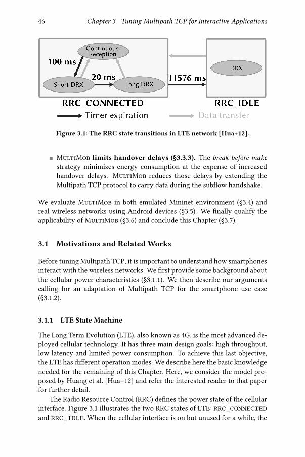
46 Chapter 3. Tuning Multipath TCP for Interactive Applications
Figure 3.1: The RRC state transitions in LTE network [Hua+12].
� MultiMob limits handover delays (§3.3.3). The break-before-make
strategy minimizes energy consumption at the expense of increasedhandover delays. MultiMob reduces those delays by extending theMultipath TCP protocol to carry data during the sub�ow handshake.
We evaluate MultiMob in both emulated Mininet environment (§3.4) andreal wireless networks using Android devices (§3.5). We �nally qualify theapplicability of MultiMob (§3.6) and conclude this Chapter (§3.7).
3.1 Motivations and Related Works
Before tuning Multipath TCP, it is important to understand how smartphonesinteract with the wireless networks. We �rst provide some background aboutthe cellular power characteristics (§3.1.1). We then describe our argumentscalling for an adaptation of Multipath TCP for the smartphone use case(§3.1.2).
3.1.1 LTE State Machine
The Long Term Evolution (LTE), also known as 4G, is the most advanced de-ployed cellular technology. It has three main design goals: high throughput,low latency and limited power consumption. To achieve this last objective,the LTE has di�erent operation modes. We describe here the basic knowledgeneeded for the remaining of this Chapter. Here, we consider the model pro-posed by Huang et al. [Hua+12] and refer the interested reader to that paperfor further detail.
The Radio Resource Control (RRC) de�nes the power state of the cellularinterface. Figure 3.1 illustrates the two RRC states of LTE: RRC_CONNECTEDand RRC_IDLE. When the cellular interface is on but unused for a while, the

3.1. Motivations and Related Works 47
Power (mW) Duration (ms)Screen o� (base) 11.4 N/AScreen 100% on 847.2 N/ALTE promotion 1210.7 260.1
LTE RRC_CONNECTED Short DRX 1680.2 1 (period: 20)LTE RRC_CONNECTED Long DRX 1680.1 1 (period: 40)LTE RRC_CONNECTED tail base 1060 11576
LTE RRC_IDLE DRX 594.3 43.2 (period: 1280)Wi-Fi promotion 124.4 79.1Wi-Fi tail base 119.3 238.1
Wi-Fi beacon (idle) 77.2 7.6 (period: 308.2)
Table 3.1: LTE and Wi-Fi power model [Hua+12].
LTE is in the RRC_IDLE mode. The antenna is then in Discontinuous Recep-tion (DRX ). This mechanism enables the interface to periodically wake up forshort instants — 43 ms in RRC_IDLE— while staying asleep for longer periodsof time — 1.28 s in this case. This limits the power consumption compared toa continuously turned on antenna. Once the cellular interface needs to sendor receive a packet, the antenna promotes from the RRC_IDLE state to theRRC_CONNECTED one. This promotion typically lasts for a few hundreds ofmilliseconds — 260 ms in our model — before the interface becomes readyfor transmission. Therefore, if the smartphone wants to send a packet whilebeing initially in RRC_IDLE state, there will be a delay between the requestto send and the actual packet transmission by the cellular antenna. Upon pro-motion completion, the LTE interface is in Continuous Reception mode wherepackets can be sent and received. The antenna stays in this mode until no datahas been sent or received for 100 ms. The LTE then enters in DiscontinuousReception. Two DRX sub-modes are present in the RRC_CONNECTED state.Both monitor the LTE network for a short time — 1 ms — and then put theantenna in a lower power mode for a longer period — 20 ms for Short DRX ,40 ms for Long DRX . On one hand, if data needs to be transmitted or receivedwhile being in one of the DRX modes, the antenna directly goes to the Contin-uous Reception mode. On the other hand, if the antenna observes no networkactivity in RRC_CONNECTED for 11576 ms, it switches to the RRC_IDLE state.
Each LTE mode has di�erent power consumption as shown in Table 3.1.The cellular interface consumes more energy when interacting with the net-work than when idle. Yet, the RRC_CONNECTED tail base, i.e., the "sleep"state of DRX , has a non-negligible energy impact. It consumes more than asmartphone screen with maximum luminosity. Also, an idle device stays formore than 11 seconds in the RRC_CONNECTED state. For the transmission of

48 Chapter 3. Tuning Multipath TCP for Interactive Applications
a single packet, starting from the idle mode, the energy consumption fromthe interface promotion to the end of the tail for LTE and Wi-Fi are respec-tively 12.8 J (for 11.836 s) and 0.04 J (during 0.317 s). The energy consumedper bit ratio can be very high for LTE, especially when only a few packets aresent. The attentive reader will notice that Table 3.1 does not characterize thepower consumption of the Continuous Reception mode. It actually dependson several factors, such as the throughput of the network and the fraction ofuplink tra�c. As a lower bound, we assume that the Continuous Receptionmode has the same power consumption as the one of the On mode of theRRC_CONNECTED Short DRX , i.e., 1680 mW.
3.1.2 Multipath TCP on Smartphones
We outline in this section some lessons we learned based on discussions withnetwork operators, measurements with friendly users and previous works.
Smartphone applications rarely perform bulk transfers. MultipathTCP was designed to aggregate bandwidth and many articles evaluatewhether it reaches that objective [Rai+11a; Che+13; PKB13; Paa+14; Den+14].However, both previous works [Fal+10] and our measurements (§2.2) showthat smartphones rarely exchange very large �les. Most of the connectionscarry a few KB. We also notice that many connections experience large idletimes. To illustrate this, we performed passive measurements by followingthe methodology described in Section 2.2.1, except that we collect the networktra�c on the client to get the smartphone’s viewpoint. Figure 3.2 shows themaximum idle time observed by each of the 183 383 collected Multipath TCPconnections carrying data. Most of them experience idle times of less thanone second. Nonetheless, 15.8% of the connections face more than 10 secondsof idle time between two consecutive data packets. From TCP’s point of view,an idle connection is not a problem. Yet, from a battery consumption view-point, an idle connection can consume energy if the radio needs to remainactive to support it.
Many sub�ows do not carry data. The full-mesh path manager im-mediately creates sub�ows on all active interfaces. Our measurements inSection 2.2.3 show that 76% (resp. 86%) of the �rst additional sub�ows areestablished within the �rst 100 ms (resp. 1 s) of the connection. Unfortu-nately, most of these sub�ows are useless. Around 75% of the Multipath TCPconnections do not send any data over the additional sub�ows, i.e., all datais exchanged over the initial path. With the default packet scheduler, ifthe �rst sub�ow exhibits a lower round-trip-time than the additional ones,Multipath TCP will only use the initial one. Previous works also indicate that

3.1. Motivations and Related Works 49
10−4 10−3 10−2 10−1 100 101 102 103 104
Maximum Idle Time between Packets [s]
0.0
0.2
0.4
0.6
0.8
1.0C
DF
over
Con
nection
s
Any Packet
Between Data
Figure 3.2: On smartphones, it is frequent to observe connections experienc-ing idle times of tens of seconds.
Multipath TCP can even perform worse than TCP with short �ows in hetero-geneous networks [Han+15; Nik+16].
Mismatchwith user expectations. As previously emphasized, most usersfavor Wi-Fi over cellular for both monetary and power consumption rea-sons [Hua+12; Nik+15; CSP17]. They expect that their smartphone will useWi-Fi whenever it works well and will switch to cellular only if it bringssome bene�ts. However, the packet scheduling decision is taken by thesender of the packet. In practice, our measurements (§2.2.2) and previousworks [Fal+10] indicate that smartphones mainly receive data, meaning thatmost of the scheduling decisions are taken by remote servers. The defaultpacket scheduler considers the path with the lowest estimated round-trip-time as the best one to send the next data. With the decreasing latency of theLTE connectivity and network operators providing Wi-Fi access, the cellularpath can sometimes exhibit a lower latency than the Wi-Fi one [SB12]. Theserver scheduling decisions can therefore go against the user expectations.
Backup sub�ows consume too much energy. According to the Multi-path TCP speci�cation [rfc6824], one way to minimize the utilization of theLTE connectivity is to always establish the cellular path as a backup sub-�ow [Lim+14a]. While being useful in mobility scenarios, there is no pointin creating backup sub�ows if the primary one does not face any connec-

50 Chapter 3. Tuning Multipath TCP for Interactive Applications
tivity issue. Indeed, energy consumption is a major concern for mobile de-vices [BBV09; CH10; CSP17], and many works explore various solutions tolimit the battery usage on smartphones [Ra+10; Che+15]. However, as sug-gested by Section 3.1.1 and previous works [Den+14], opening a sub�ow onthe cellular interface without using it is expensive from an energy consump-tion viewpoint, the Wi-Fi interface consuming at least �ve times less thanthe LTE one [Nik+15]. In the remaining of this Chapter, we consider the LTEmodel proposed by Huang et al. [Hua+12] described in Section 3.1.1 to esti-mate the cellular power consumption. We expect similar results with othermodels [Nik+15]. Based on our model, we identify user-initiated connectionsin Multipath TCP Backup mode that create cellular sub�ows without sendingdata on them. In our passive measurements, we observe 12 988 connectionsthat created 628 RRC_CONNECTED periods on cellular and consumed morethan 4670 J just because of the Syn sent. Our LTE model [Hua+12] indicatesthat for a smartphone, opening a single cellular sub�ow is equivalent, froma energy consumption viewpoint, to lighting up the screen at 100% duringthe RRC_CONNECTED period, which lasts more than 11 s. Preventively open-ing the cellular sub�ow as previously proposed [Paa+12] is therefore veryexpensive from the battery perspective. Despite this, both Apple’s Siri andthe interactive mode of iOS Multipath TCP still create cellular sub�ows at thebeginning of the connections.
Related works. Pluntke et al. [PEK11] is the �rst work addressing the en-ergy concern with Multipath TCP by proposing a packet scheduler aiming tominimize the power consumption. It does not take into account mobile situa-tions. Peng et al. [Pen+14] introduce various algorithms to optimize both en-ergy consumption and throughput for �le transfer and video streaming. How-ever, they only rely on simulations. Lim et al. [Lim+14a] propose eMPTCP,an energy-e�cient Multipath TCP version for mobile devices. In practice, itproposes a path manager delaying the establishment of the cellular sub�owuntil a given threshold of transferred bytes is crossed. In addition, it also shipsa packet scheduler that selects the cellular path only if the Wi-Fi throughputis not su�cient. While working with bulk transfers, interactive applicationscan transmit very few bytes and do not require large bandwidth. Furthermore,eMPTCP does not consider device mobility. Sinky et al. [SHG16] propose torely on the signal strength of the Wi-Fi network to tune the congestion win-dow to trigger seamless Wi-Fi handover with bulk transfer. However, it wasonly tested under NS3-DCE environment and not with actual devices. Hanet al. [Han+16] propose a packet scheduler that stops using the cellular net-work when the Wi-Fi is su�cient to support delay-tolerant tra�c. However,interactive applications are typically delay-sensitive and the solution doesnot discuss the unused cellular sub�ows. Frömmgen et al. [Fro+16] suggest

3.2. Mimicking Apple’s Siri Tra�c 51
a packet scheduler duplicating data packets on all available network paths.While it ensures low-latency delivery, such strategy does neither take energyconsumption into account nor consider user policy who prefers Wi-Fi overcellular networks.
3.2 Mimicking Apple’s Siri Tra�c
Voice-activated applications will likely play a growing role on smartphones incoming years [Hem16; Kni16]. One of them is Apple’s Siri assistant. Despitebeing the �rst application using Multipath TCP at large scale [BS16], little isknown about the Siri tra�c. Asse� et al. [Ass+16] analyze the reaction of Sirito losses and jitter but do not provide any model of the tra�c produced bythis application.
Siri interacts with a few well-known servers. To characterize its tra�c,we captured all the packets exchanged with these servers from a universitycampus network serving several thousands of wireless devices during a week.We focus our analysis on the 18 166 Multipath TCP connections that did notperform any handover to a cellular network since we only captured packetsover the Wi-Fi one. This can be assessed with TCP’s sequence number andMultipath TCP’s Data Sequence Number.
Siri runs over HTTPS, probably to ensure privacy and also to reduce therisk of middlebox interference. The client sends requests that are immediatelyanswered by the server. Figure 3.3 presents some statistics extracted from theSiri trace. 60% of the Siri connections last between 5 and 10 seconds. Thistime is likely correlated to the time needed to ask a question to the assistantand getting back the reply. Notice that 15% of the connections last more than20 seconds, perhaps because of successive user interactions with the Siri ap-plication. Figure 3.3b shows that 77% of the data packets sent by Siri clientshave a size between 50 and 500 bytes. Only 7% of client-generated packetsare larger than 1000 bytes. Looking at the connection behavior, several smallpackets are sent within a few microseconds to form bursts of a few thousandsof bytes. This tra�c pattern is probably related to the voice sampling process.In comparison, MSS-sized packets represent only 20% of the packets sent bythe server. The large fraction of short packets also suggests that the Siri appli-cation disables the Nagle algorithm to avoid delaying packet transmissions.
To evaluate the interplays between a simple interactive application andMultipath TCP, we use a simpli�ed model of the observed Siri behavior. Ourmodel is a client-oriented process with three states as shown in Figure 3.4.The client maintains the sent counter. In the Sending burst state, the clientsends a burst of 2500 bytes using packets carrying between 50 and 500 bytes.Then sent is incremented and the client waits in the Inter-burst wait statebefore going back to Sending burst . Once sent reaches sent_thres, the

52 Chapter 3. Tuning Multipath TCP for Interactive Applications
10−2 10−1 100 101 102 103 104
Connection Time [s]
0.0
0.5
1.0C
DF
(a) Duration of the Multipath TCP connections created by Apple’s Siri.
100 101 102 103
Size of Client Packets [Byte]
0.0
0.5
1.0
CD
F
(b) Size of the data packets sent by Siri clients.
100 101 102 103
Size of Server Packets [Byte]
0.0
0.5
1.0
CD
F
(c) Size of the data packets returned by Siri servers.
Figure 3.3: Analysis of the Siri traces collected on the campusWi-Fi network.
Figure 3.4: Client-side state machine of a simple voice activated application.

3.3. Tuning Multipath TCP 53
Figure 3.5: MultiMob high-level architecture.
client switches to the Inter-request wait state representing the delay betweensuccessive user interactions. We empirically set sent_thres to 9, and thedurations of the Inter-burst wait and Inter-user interaction wait states are 1/3 sand 5 s, respectively. We model the server as a process returning a 750 bytesresponse after each burst. Our simple client application then collects the delaybetween each request and its associated server response. Both our client andserver applications disable both Nagle’s and Cork’s algorithms. Unless explic-itly stated, all the measurements presented in the following of this Chapterare based on this tra�c pattern.
3.3 Tuning Multipath TCP
We now explain how MultiMob improves the Linux Multipath TCP imple-mentation for the smartphone use case. Figure 3.5 illustrates the high-levelarchitecture of MultiMob. We �rst add to the server’s packet scheduler aheuristic that enables it to infer the wireless conditions a�ecting the clientsub�ows (§3.3.1). Second, we adopt a break-before-make path managementby implementing an oracle that monitors the network and opens cellular sub-�ows only when needed (§3.3.2). Third, we extend the Multipath TCP pro-tocol so that the client can retransmit data inside the Syn used to create anadditional sub�ow during a network handover (§3.3.3).
3.3.1 Towards Global Packet Scheduling
When a Multipath TCP connection has 2 or more sub�ows, each of the com-municating hosts independently selects its best sub�ow to transmit each datapacket. The Linux implementation relies on the default packet sched-uler selecting the available sub�ow having the lowest estimated round-trip-time (RTT). This packet scheduler works well in a variety of environ-ments [Paa+14]. However, selecting sub�ows only on the basis of their es-

54 Chapter 3. Tuning Multipath TCP for Interactive Applications
Algorithm 1 isNewerThan(B 5 , >B 5 )Input: B 5 a sub�ow, >B 5 another sub�ow or NoneOutput: Return true if sf
1: if >B 5 is None then return true2: if B 5 has newer original reception than >B 5 then3: return true ⊲ See text for de�nition4: return false
Algorithm 2 MultiMob’s server-side packet scheduler tracks the sub�owthat was most recently used by the client.Output: 14BCB 5 next sub�ow to use
1: 14BCB 5 ←None2: for B 5 in working sub�ows where data was not sent yet do3: if isNewerThan(B 5 , 14BCB 5 ) then ⊲ See Algorithm 14: if B 5 is available then5: 14BCB 5 ← B 5
6: return 14BCB 5
timated RTT is not always the best solution. Consider a smartphone userthat moves while using the Siri application. It regularly sends small burstsof data and the server returns responses. In an environment where the Wi-Finetwork features a lower latency than the cellular network, the packet sched-uler will prefer the Wi-Fi path. As the generated tra�c is low, its congestionwindow will remain open as long as the Wi-Fi network behaves well. If thesmartphone detects that the Wi-Fi starts being lossy, it will shift its tra�cover the cellular sub�ow. Nevertheless, the server is not aware of the smart-phone’s motion and its packet scheduler still sends responses over the Wi-Fisub�ow because it exhibits the lowest latency. The server will only switchto the cellular sub�ow after the expiration of its retransmission timer, whichpotentially wastes from hundreds of milliseconds to several seconds.
To solve this problem, MultiMob includes a server-side packet schedulerthat uses the most recent data sent by the smartphone as a hint to select themost suitable sub�ow. On the smartphone, MultiMob uses the defaultpacket scheduler while setting the cellular interface as a backup one. Thisenables the smartphone to favor the Wi-Fi path and only use the (backup) cel-lular sub�ow when the Wi-Fi one experiences retransmissions. Algorithm 2describes the operations of the server-side MultiMob packet scheduler. Itmaintains for each sub�ow the timestamp of the last original packet receivedover it. A packet is considered to be original if it contains new data (basedon its Multipath TCP Data Sequence Number) or if it successfully concludes a

3.3. Tuning Multipath TCP 55
sub�ow establishment. Similarly, an acknowledgment is viewed as original ifits Data ACK advances the lower edge of the sending window. TheMultiMobscheduler removes from consideration the potentially failed sub�ows and theones where this data has already been transmitted. Then it iterates over allremaining sub�ows to identify the one having the most recent original re-ception. If the congestion window of this sub�ow is not full, the schedulerselects it.
Thanks to the MultiMob packet scheduler, the server can quickly detectthe most suitable sub�ow while taking into account sub�ow backup prefer-ences. For an interactive application like Siri that sends small requests, thetra�c will not completely �ll the congestion window and the server will al-ways reply on the sub�ow that was last used by the client.
3.3.2 Break-Before-Make Path Management
In the Linux kernel implementation, when a Multipath TCP connection starts,the full-mesh path manager initiates the exchange over the primary net-work interface and then additional sub�ows over the other ones. If we con�g-ure the cellular interface as a backup one, data packets will only be sent overthat network once the Wi-Fi network fails. This make-before-break approachminimizes the amount of data sent over the cellular interface. Unfortunately,this strategy does not minimize energy consumption. Between an exchangecarrying a few KB of payload and another one containing only Syn and Finpackets, there is little di�erence from a power consumption viewpoint. Re-call that in Section 3.1.2, we highlighted a set of Multipath TCP connectionskeeping the cellular interface in the power-hungry RRC_CONNECTED modeby establishing sub�ows without using them.
MultiMob opts for a break-before-make approach and creates sub�owsover the backup interfaces after having detected failures on the primary ones.With break-before-make, the key issue from a performance viewpoint be-comes how quickly can the smartphone detect that a wireless interface worksbadly in order to establish backup sub�ows. MultiMob includes two mecha-nisms signaling when the backup interface must be used. First, the client em-beds an oracle that monitors the connections’ state to create sub�ows when itexperiences sending issues (§3.3.2.1). Second, MultiMob extends the Multi-path TCP protocol to inform the peer about additional data to be received(§3.3.2.2).
3.3.2.1 Monitoring Connection Status
When sending packets over a wireless network, the smartphone may observedelivery failures. In particular, we can assume that if a network interface ex-periences connectivity issues, sub�ows using it will experience retransmis-

56 Chapter 3. Tuning Multipath TCP for Interactive Applications
IPsrc IPdst Network interface TCP sub�ows TCP stats1.2.3.4 4.5.6.7 Wi-Fi [tp1, tp3] sloss 2%,. . .2.3.4.5 5.6.7.8 Cellular [tp2] sloss 0%,. . .2.3.4.5 4.5.6.7 Cellular [tp4, tp5] sloss 15%,. . .
Table 3.2: Oracle monitoring table example.
sions and losses, even if they belong to di�erent connections. MultiMobrelies on this assumption to spot network connectivity problems through aMultipath TCP oracle implemented as a kernel module. To track those events,our oracle maintains a monitoring table of netpaths as shown in Table 3.2. Anetpath is a tuple (IPsrc, IPdst, network interface). By aggregating this infor-mation on a per network �ow basis we reduce the size of the monitoring tablecompared to a per transport �ow one. Such structure is well adapted to realdeployments using proxies [KT; Tes19] where all Multipath TCP connectionsare terminated on a proxy.
When a new sub�ow is created, the oracle checks if its correspondingnetpaths is already in the table. If so, the sub�ow is added to the list of TCPsub�ows matching this entry. Otherwise, a new entry is created. When asub�ow stops, it is removed from the sub�ow list it belongs to. If a netpathdoes not have any associated sub�ow anymore, its entry is removed from themonitoring table.
Our oracle computes every )B seconds statistics based on the sub�owsassociated to a given netpath. Our implementation collects three1 metrics:smoothed loss rate (sloss), smoothed retransmission rate (sretrans) andmaximum RTO. Those statistics are computed based on the per-sub�ow statemaintained by the Linux kernel. It also takes into account Tail Loss Probes(TLP) [Duk+13]. When the TLP timer �res, we enter Forward Acknowledg-ment mode and the packet at the head of the write queue is marked as lost.
The oracle computes the smoothed rates — sloss and sretrans — byusing Volume-weighted Exponential Moving Averages (V-EMA), similar towhat Android uses to estimate the loss rate of Wi-Fi beacons. These V-EMAsreduce to the three following equations
E0;8+1 =?A>38+1E>;8+1
(3.1)
1The perceptive reader will notice that we collect information on an interface basis withoutconsidering link-layer metrics such as Wi-Fi beacons. Actually, we wanted to compile suchinformation but we faced practical issues. Nexus 5 smartphones use a Broadcom Wi-Fi cardand a Qualcomm GSM one both requiring proprietary drivers and we did not found a wayto collect their metrics in the kernel. As these data are made available to the Android OS,it should be possible to make them available for the Linux kernel too. Yet, we leave this forfuture work.

3.3. Tuning Multipath TCP 57
Parameter Meaning
slossthresThreshold value of sloss that triggers
backup sub�ow creations on the netpath
sretransthresThreshold value of sretrans that triggers
backup sub�ow creations on the netpath)B Period between each V-EMA computationU Sensitivity parameter of the V-EMA equations
Table 3.3: The di�erent parameters of the oracle.
?A>38+1 = U (E0;=4F · E>;=4F) + (1 − U)?A>38 (3.2)
E>;8+1 = U · E>;=4F + (1 − U)E>;8 (3.3)
where E0;=4F is the new value of the studied metric (e.g., number of lost sentpackets during the last)B period), E>;=4F is the volume of this new value (e.g.,total number of packets sent during the last )B period), ?A>38 is the productat iteration 8 , E>;8 the volume at iteration 8 and E0;8 the value of the V-EMAat iteration 8 . Note that ?A>30 = E>;0 = E0;0 = 0 and no value is computed ifE>;=4F = 0. U ∈ [0, 1] is a sensitivity parameter experimentally set to 0.5, asAndroid.
The MultiMob oracle sets thresholds to detect under-performing net-paths. Once a threshold is crossed, MultiMob triggers the creation of backupsub�ows for all connections associated to the under-performing netpath. Italso marks the sub�ows associated with that netpath as potentially failed.Since the oracle is part of the Linux kernel, it can query the state of all es-tablished Multipath TCP connections. It can then prompt backup sub�owscreation once any connectivity issue is detected. All the oracle parametersare summarized in Table 3.3.
3.3.2.2 Signaling Idle Connections
As it is based on indications of sending issues, our Multipath TCP oracle aloneis not su�cient to trigger the backup interface usage under all possible tra�cpatterns. In particular, consider a smartphone-initiated download. Duringsuch transfer, the server pushes data towards the client. The smartphone onlysends Acks to the server. However, TCP does not ensure the reliable deliveryof the Ack packets once they do not contain any payload. If the primarysub�ow fails, the smartphone will stop receiving data, but it is di�cult forthe Multipath TCP stack to distinguish between losses in the network andthe server application becoming idle for any reason, especially when no othernetwork tra�c is running concurrently.

58 Chapter 3. Tuning Multipath TCP for Interactive Applications
0 1 2 3 4 5 6 7 8 9 10 11 12 13 14 15 16 17 18 19 20 21 22 23 24 25 26 27 28 29 30 31
Kind Length Subtype (Reserved) I F mM a A
Data ACK (only if A set, 8 bytes if a set else 4 bytes)
Data Sequence Number (only if M set, 8 bytes if m set else 4 bytes)
Subflow Sequence Number (only if M set)
Data-Level Length (only if M set) Checksum (only if M set)
Figure 3.6: The modi�ed Multipath TCP Data Sequence Signal option.
A �rst naive approach would be to let the client regularly probe the serverwith keep-alives. Such active probing would consume energy and could de-grade wireless performance [Hu+15]. With HTTP, another solution would bethat a Multipath TCP aware client uses the Content-Length header sent bythe server to detect idle times in the middle of a transfer to create an additionalsub�ow, e.g., via the enhanced socket API [HB16].
To let all applications bene�t from such information without modifyingthem, MultiMob extends Multipath TCP so that the server can indicate tothe client that a data transfer is not �nished yet. We de�ne two signals. The�rst one is sent in the Multipath TCP Data Sequence Signal (DSS) option. Wetake one of the unused bit in the reserved �eld of the DSS and call it the Idle
bit, as shown in Figure 3.6. A host sets the Idle bit when it sends a data packetthat empties its send bu�er. Otherwise, the Idle bit is reset. Since this bit isincluded in the DSS option, it is sent reliably to the peer. Then, a receiverdoes not expect a connection to be idle unless it has received a DSS optionwith the Idle bit set. Notice that the Multipath TCP’s Idle bit di�ers from theTCP’s Push one used to signal that the carried data must be promptly deliv-ered to the receiver. Although the Push bit is typically set when the carrieddata empties the sending bu�er (like with SSH), our experiments revealed thatit is often set in many MSS-sized packets during bulk exchanges. The secondsignal indicates after how much idle time the receiving host should trigger thecreation of backup sub�ows. For this, we rely on the Experimental MultipathTCP option [rfc6824b] that carries the current value of the sender’s RTO. Theclient sends an request RTO option from time to time and the server returnsthe same option containing its current retransmission timer RTOserver. Thereceiving host uses that value to set its idle timer at max(500 ms, RTOserver).This timer is restarted each time it receives a data packet having its Idle bit re-set, and stopped if the last data packet had the Idle bit set. If the timer expires,the stack informs the oracle that triggers the creation of backup sub�ows.

3.3. Tuning Multipath TCP 59
3.3.3 Immediate Reinjections
The break-before-make approach described in the previous section is bene�-cial from an energy viewpoint. However, a mobile typically detects the fail-ure of a wireless interface by the expiration of its retransmission timer orusing Tail Loss Probe (TLP). This unacknowledged data can only be retrans-mitted over another interface once a sub�ow has been established over thisnetwork. Such establishment requires a four-way handshake, as described inSection 1.3.2. While this ensures complete authentication of both connectionparticipants, this handshake unfortunately delays the reinjection of the lostdata, since the client needs to wait for two network round-trip-times on thebackup interface.
To reduce this delay, we extend Multipath TCP to support the transmis-sion of data inside Syn packets and immediately after Syn/Ack ones. For this,we de�ne two new Multipath TCP options: Fast Join In and Fast Join Out.These are di�erent from TCP Fast Open [Rad+11; rfc7413] because a newsub�ow is established between hosts that already share state for one Multi-path TCP connection.
A naive approach would be to simply place data inside the Syn and re-quire the server to accept it immediately. Unfortunately, this solution wouldinduce obvious security problems because this Syn is not authenticated. WithMultipath TCP, the Syn initiating an additional sub�ow carries the Mp Joinoption containing a random number used to authenticate the server in ad-dition to the 32-bit token that identi�es the connection. This token alone isnot su�cient to authenticate the client because a passive listener might haveobserved it during the establishment of a previous sub�ow for the same con-nection [rfc6181], e.g., on an open Wi-Fi network.
The Fast Join Out option described in Figure 3.7 addresses this issue andallows the client to carry data in the initial Syn without causing any securityissue. Note that as there is only 40 bytes for TCP options and current popu-lar ones found in Syn packets are Maximum Segment Size (4 bytes), SelectiveAck (2 bytes), Timestamps (10 bytes) and Window Scale (3 bytes + 1 paddingbyte), the Fast Join Out option must be engineered to �t into 20 bytes. Ashighlighted by Figure 3.8, the Fast Join Out option in the initial Syn is 20-byte long and contains three important �elds. First, the token TokenS iden-ti�es the Multipath TCP connection as in the Mp Join option. Second, theData Sequence Number (DSN) indicates the Multipath TCP sequence numberof the data contained in the Syn payload. The associated DSNC must be the�rst unacknowledged data byte. Third, the 32-bit truncated HMAC (HMACC)authenticates the client. Its computation is the following
HMACC = HMACKS || KC(TokenS || DSNC) (3.4)

60 Chapter 3. Tuning Multipath TCP for Interactive Applications
Client Server
SYN + Fast Join Out (TokenS , DSN
C , HMACC) + DATA
Get DSNC
Compute HMACC
Lookup TokenS
Verify HMACC
Get Data ACKS
Compute HMACS
SYN/ACK + Fast Join Out (Data ACKS, HMACS
)
DATA...Verify HMACS
ACK
DATA...
Figure 3.7: With Fast Join Out, the client can directly send data inside theSyn packet.
0 1 2 3 4 5 6 7 8 9 10 11 12 13 14 15 16 17 18 19 20 21 22 23 24 25 26 27 28 29 30 31
Kind = 30 Length = 20 ST = 10 Rsv B Address ID
Receiver’s Token
Data Sequence Number
Sender’s Truncated HMAC
Data-Level Length Checksum
Figure 3.8: The Fast Join Out option in the initial Syn.
0 1 2 3 4 5 6 7 8 9 10 11 12 13 14 15 16 17 18 19 20 21 22 23 24 25 26 27 28 29 30 31
Kind = 30 Length = 16 or 20 ST = 10 Rsv a B Address ID
Sender’s Truncated
HMAC
Data ACK (8 bytes if a set else 4 bytes)
Figure 3.9: The Fast Join Out option in the Syn/Ack.

3.3. Tuning Multipath TCP 61
where KC and KS are respectively the connection keys of the client and serverthat were exchanged during the Multipath TCP connection handshake. Toprevent replay attacks, our implementation accepts only one Syn containingthe Fast Join Out option for a given DSNC. To be eligible, the DSNC presentin the Fast Join Out option should match the one expected by the server.However, Acks packets might not have reached the client. To cope with thissituation, we de�ne EDSN as the next Expected DSN by the server and DSNC
as the DSN contained in the Fast Join Out option of the Syn packet. Theserver accepts the establishment of the sub�ow if the following inequalityholds
EDSN - wndrcv ≤ DSNC ≤ EDSN (3.5)
where wndrcv is the receive window of the server. Notice that the Fast JoinOut option also carries both the Data-Level Length and Checksum �elds.Similar to the Multipath TCP DSS option, this information enables the re-ceiver to detect middlebox interference a�ecting the data. The B bit indicateswhether the client wants to consider this new sub�ow as a backup one.
To authenticate the server, it computes the following HMACS
HMACS = HMACKC || KS(DSNC || Data ACKS) (3.6)
where DSNC is the Data Sequence Number contained in the Syn packet andData ACKS is the value of the acknowledged Multipath TCP sequence num-ber, possibly updated by the data received. The server then sends a Syn/Ackpacket with the Fast Join Out option carrying both the computed HMACS
and the updated Data ACKS, as described in Figure 3.9. Once it sent theSyn/Ack packet, the server can start sending data. At the reception of theSyn/Ack packet, the client �rst checks that the Data ACKS value is in theexpected range, i.e.,
DSNC + Data-Level LengthC ≤ Data ACKS ≤ LUSBC + 1 (3.7)
where Data-Level LengthC is the Data-Level Length value sent in the Synpacket and LSUBC is the largest unacknowledged sent byte by the client overthe Multipath TCP connection. If the inequality holds, the client can checkthe computed HMACB using Equation 3.6. If it matches, it replies with anAck packet and the additional sub�ow is established.
The Fast Join Out option is useful when the mobile client sends data toa remote host. However, there are situations where only the server pushesdata towards the client. A �rst typical example are streaming applicationswhere the server pushes data at a regular rate. Another example is a longclient-initiated �le download. When the oracle running on the mobile clientdetects losses or the absence of data, it may want to quickly establish a sub-�ow without having data to send to the remote host. Such path creation can
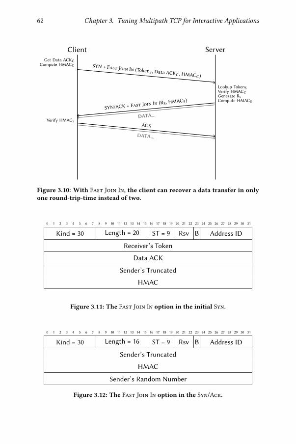
62 Chapter 3. Tuning Multipath TCP for Interactive Applications
Client Server
SYN + Fast Join In (TokenS , Data ACK
C , HMACC)
Get Data ACKC
Compute HMACC
Lookup TokenS
Verify HMACC
Generate RS
Compute HMACS
SYN/ACK + Fast Join In (RS, HMACS
)
DATA...Verify HMACS
ACK
DATA...
Figure 3.10: With Fast Join In, the client can recover a data transfer in onlyone round-trip-time instead of two.
0 1 2 3 4 5 6 7 8 9 10 11 12 13 14 15 16 17 18 19 20 21 22 23 24 25 26 27 28 29 30 31
Kind = 30 Length = 20 ST = 9 Rsv B Address ID
Receiver’s Token
Data ACK
Sender’s Truncated
HMAC
Figure 3.11: The Fast Join In option in the initial Syn.
0 1 2 3 4 5 6 7 8 9 10 11 12 13 14 15 16 17 18 19 20 21 22 23 24 25 26 27 28 29 30 31
Kind = 30 Length = 16 ST = 9 Rsv B Address ID
Sender’s Truncated
HMAC
Sender’s Random Number
Figure 3.12: The Fast Join In option in the Syn/Ack.

3.4. Emulation Results 63
then enable the server to continue its data transfer. This case is covered by theFast Join In option whose operations are described in Figure 3.10. Actually,this option is very similar to the Fast Join Out one. Instead of computingHMACC with the DSN, Fast Join In uses the current client-side Data ACK
value.HMACC = HMACKS || KC
(TokenS || Data ACKC) (3.8)
The client then sends this value along with the associated Data ACKC in theFast Join In option in the Syn packet as shown in Figure 3.11. The Syn packetis only considered if the carried Data ACKC �ts in the expected server range,i.e.,
SUSDS ≤ Data ACKC ≤ LUSDS + 1 (3.9)
where SUSDS and LUSDS are respectively the smallest and the largest unac-knowledged sent bytes by the server. If the inequality is true, the receivinghost can verify the HMACA computation using Equation 3.8. In order to pre-vent replaying attacks, the server only accepts a given Data ACKC value oncefor a given connection. Note that compared to the Fast Join Out one, theFast Join In option in the Syn packet does not carry Data-Level Length norChecksum �elds, as there is no payload in such packets. This leaves morespace to support 8-byte long HMAC.
The main di�erence between Fast Join Out and Fast Join In residesin the Syn/Ack packet. While the Data ACKS provided in the Fast Join OutSyn/Ack can possibly acknowledges previously sent client data, the next DSNto be sent by the server is necessarily Data ACKC. To avoid deterministicvalue, the server instead generates a random value RB as in classical Mp Joinand communicates it to the client as shown in Figure 3.12. Therefore, theHMACS is computed as follows.
HMACS = HMACKC || KS(Data ACKC || RS) (3.10)
Once the Syn/Ack is sent, the server can immediately transfer data over thisnew sub�ow. At the other side, once the Syn/Ack has been received and theHMACS veri�ed, the client considers the sub�ow as established. With FastJoin In, a download-only data transfer can be resumed within one round-trip-time, instead of two with normal Mp Join.
3.4 Emulation Results
In this Section, we evaluate each of the MultiMob components in Mininetenvironment [Han+12]. We consider a scenario with two disjoint paths be-tween the client and the server as illustrated in Figure 3.13. Our emulationsuse Multipath TCP v0.91 in the Linux kernel 4.1. Unless explicitly stated,the primary path exhibits a round-trip-time of 15 ms and the additional one

64 Chapter 3. Tuning Multipath TCP for Interactive Applications
Figure 3.13: The studied network topology in our emulations.
0 200 400 600 800 1000 1200 1400Max Delay [ms]
0.0
0.5
1.0
CD
F
Default, no loss
MultiMob, no loss
Default, lost
MultiMob, lost
Figure 3.14: Maximum delay to return an answer to simpli�ed interactiverequests. Each scenario ran 25 times. 100% losses generated by a netem com-mand begin to occur on the primary path when the client is in Inter-requestwait state, i.e., between request bursts.
25 ms. Both paths have a bandwidth of 10 Mbps and the router queue sizesare equal to the bandwidth-delay product. When the simpli�ed interactivetra�c is tested, it runs for 20 s.
We �rst evaluate the impact of the MultiMob server-side scheduler(§3.4.1). We then show that the packet scheduler alone is not su�cient anddiscuss how the operations of the oracle are a�ected by the threshold val-ues (§3.4.2) and the periodicity of the V-EMAs computations (§3.4.3). Next,we demonstrate the bene�ts of the Idle bit (§3.4.4) and �nally assess the timesaved by using Fast Join Out compared to the normal Mp Join (§3.4.5).
3.4.1 MultiMob Server-Side Packet Scheduler
In this simple scenario, the client opens the connection over the primary pathand then creates a backup sub�ow over the additional one. We test di�erentpacket schedulers on the server. Figure 3.14 shows that when there is no loss,both the default and the MultiMob server-side packet schedulers exhibitquite similar performances. Notice that since the Linux sysctl tcp_slow_-start_after_idle is set to 1, a request can be answered within two RTTs

3.4. Emulation Results 65
0 500 1000 1500 2000 2500 3000 3500Max Delay [ms]
0.0
0.5
1.0C
DF
Default, no oracle
MultiMob, no oracle
Default, oracle
MultiMob, oracle
Figure 3.15: Maximum delay to return an answer to simpli�ed interactiverequests. Each scenario ran 25 times. 25% losses generated by a netem com-mand begin to occur on the primary path when the client is in Inter-requestwait state, i.e., between request bursts.
if its sending phase generates more packets than the initial congestion win-dow (10 packets). However, when the primary sub�ow fails between tworequests, the MultiMob packet scheduler reduces the maximal experienceddelay by a factor of two compared to the default one. When the client sendsits �rst request after a loss, it experiences a RTO before reinjecting the packetson the additional path. Nonetheless, the server is not aware that the primarysub�ow failed. With the default packet scheduler it sends the reply on theprimary lossy path. It therefore also experiences a RTO before reinjecting theresponse on the additional sub�ow. Since the MultiMob server-side sched-uler follows the last client decision, it does not experience RTO and hencereduces the delay perceived by the application.
Notice that while the MultiMob scheduler works well when the primarypath completely fails, it is not su�cient to handle all loss patterns. Figure 3.15illustrates that when the primary path exhibits 25% random losses, the per-formance of both the default and the MultiMob packet schedulers are lesspredictable. At client side, the default packet scheduler still prefers thelowest latency sub�ow, even if lossy. The path selected by the server-sideMultiMob packet scheduler is function of the last received packet. Whilethe use of the oracle still lets the application experience delays of severalhundreds of milliseconds, it helps to decrease their variability.
3.4.2 In�uence of the Threshold Values of the Oracle
One of the foundations of our oracle is to consider currently active connec-tions as connectivity probes. Continuous and bulk transfers typically have a

66 Chapter 3. Tuning Multipath TCP for Interactive Applications
0 20 40 60 80 100Random Losses on Primary Path (%)
0
250
500
750
1000
1250
1500
1750M
ax
Delay
[m
s]
No oracle
Oracle - slossthres 10 %
Oracle - slossthres 25 %
Oracle - slossthres 40 %
(a) Maximal delay to answer a simpli�ed interactive request.
0 20 40 60 80 100Random Losses on Primary Path (%)
0
250
500
750
1000
1250
1500
Est.
Mean
Cellu
lar
Pow
er
[m
W]
No oracle
Oracle - slossthres 10 %
Oracle - slossthres 25 %
Oracle - slossthres 40 %
(b) Estimated mean power consumption of the additional path, assuming it is a cellu-lar interface, based on our model [Hua+12].
Figure 3.16: Simpli�ed interactive requests with light continuous back-ground tra�c. The second interface is set as backup. If any, the loss eventbegins when the client is in Inter-request wait state, i.e., between requestbursts. The oracle periodicity)B is 100 ms. Markers show medians and errorbars 25th and 75th percentiles over 25 runs.

3.4. Emulation Results 67
better network view than on/o� and idle ones. When they su�er from losses,such transfers make the oracle trigger the creation of backup sub�ows forall related connections, even idle ones. This enables limiting the number ofconnections experiencing RTOs before using the backup path.
To assess this, we set up a light background request/response �ow (12KB/s) and generate simpli�ed interactive request tra�c. To observe how thethreshold of V-EMA values a�ects the operations of the oracle, we focus hereon the smoothed loss rate one (slossthres). Figure 3.16a shows the maxi-mum perceived application latency to answer a request and Figure 3.16b es-timates the energy consumption of the additional backup path, consideringthat it is an always-on cellular interface. Without any loss, we observe simi-lar request delays between all con�gurations. Notice that when the oracle ispresent, it prevents the creation of the backup path. This decreases the esti-mated power consumption compared to the default full-mesh behavior di-rectly creating the backup sub�ow after the connection establishment. Whenlosses occur on the primary path, our oracle detects that the background traf-�c experiences connectivity issues, and therefore creates backup sub�ows forall connections using that netpath. Then, the simulated interactive client candirectly use the additional path and does not experience any RTO. Since theserver relies on the MultiMob packet scheduler, it replies on the sub�owused for the last request. On the contrary, if there is no oracle, the interactiveconnection client must experience a RTO before using the additional path,even if the additional sub�ow is always established at the beginning of theconnection. Furthermore, when the link is very �appy (20 to 30% of randomlosses), without the oracle the client tries to reuse the lossy primary path oncesome packets manage to use it. Our oracle prevents this behavior by consid-ering the primary path as potentially failed, discouraging the smartphone’spacket scheduler to reuse the primary path.
When using the oracle, the creation of additional sub�ows depends onthe network conditions and the slossthres parameter. When set to a lowvalue like 10%, the interactive tra�c client experiences low delays but thebackup path is quickly created, as a few losses su�ce. With higher thresholdvalues like 40%, the additional path remains closed in the median case whenthe primary path experiences 10% of random losses. However, the interactivetra�c can experience high latencies, possibly larger than without the oracle,as it cannot shift the tra�c on the non-existent backup path. Based on thoseemulation results, we experimentally set slossthres to 25% for real mobiledevices as a reasonable trade-o� between low-latency and low additional pathuse. The sretransthres is set to 50% and the maximum RTO threshold isempirically set to 1.5 s to avoid using a sub�ow that might hurt interactivitybecause of the lack of retransmission responsiveness.

68 Chapter 3. Tuning Multipath TCP for Interactive Applications
0 20 40 60 80 100Random Losses on Primary Path (%)
0
1000
2000M
ax
Delay
[m
s]
1 ms
10 ms
100 ms
500 ms
1000 ms
Figure 3.17: Varying )B with simpli�ed interactive tra�c only, withslossthres and sretransthres respectively set to 25% and 50%. Markers showmedians and error bars 25th and 75th percentiles over 20 runs.
3.4.3 In�uence of Oracle Periodicity
As suggested by the equations of the V-EMA, the reactivity of the oracle alsodepends on the smoothed computation periodicity )B . Indeed, as Figure 3.17shows, the lower )B , the quicker the reaction of the oracle to losses and thelower the variability of the detection. A value of 1 ms allows a very fast re-action, but the oracle might spend a lot of CPU time to update its monitoringtable. On the contrary, a value of 1 s is not responsive enough. In the remain-ing of our experiments, we empirically set )B to 500 ms to match sub-secondreactivity while keeping low CPU usage on mobile devices.
3.4.4 Bulk Download and Primary Sub�ow Loss
In Section 3.3.2.2, we motivated that monitoring the connections sending datais not su�cient when the smartphone only receives data. To illustrate thissituation, Figure 3.18 plots the time-sequence graph of �le download fromthe receiver’s viewpoint. After about half a second, the client detected that itdid not receive data anymore while the Idle bit was not set in the DSS option.Therefore, it triggers the creation of a sub�ow on the backup path. Once itexperiences a RTO, the server starts using the newly created sub�ow and thedata transfer succeeds. Notice that in our experience, the retransmissions at6 s were caused by a burst of duplicate Acks.
3.4.5 Fast Join Bene�ts
The primary goal of our proposed Fast Join options is to decrease the estab-lishment time of backup sub�ows. To assess this, we evaluate the bene�ts of

3.4. Emulation Results 69
0.0 2.5 5.0 7.5 10.0 12.5 15.0 17.5Time [s]
0
1
2
Seq
uen
ce
Nu
mb
er
×107
Additional subflow established
Primary
Additional
Figure 3.18: Time-sequence graph of the packets received by a client duringa 20 MB HTTP GET. The primary sub�ow su�ers from 100% losses at 1.5 s.
0 50 100 150 200 250 300 350 400Additional Path RTT [ms]
0
200
400
600
800
ΔM
ax
Delay
[m
s]
512 B
1420 B
4 KB
16 KB
Figure 3.19: Di�erence of maximum application perceived delays betweenregular Mp Join and Fast Join Out depending on the request size. To limitthe detection variability, we set the oracle periodicity)B to 1 ms. Markers aremedians over 6 × 2 runs, bars show minimum and maximum.

70 Chapter 3. Tuning Multipath TCP for Interactive Applications
the Fast Join Out option with regular request/response tra�c where the pri-mary path experiences 100% losses after �ve seconds. Figure 3.19 shows thedelta of the application-perceived delays of the �rst request following the lossevent using either Mp Join or Fast Join Out. When the request �ts inside asingle TCP packet, as for the popular Siri application, the Fast Join Out pro-vides immediate client data reinjections and the responses can be receivedafter one RTT instead of three RTTs with Mp Join. If the request requiresseveral TCP packets to be sent, Fast Join Out still saves one RTT comparedto the regular Mp Join. These results con�rm our intuitions provided by Fig-ures 1.9 and 3.7.
3.5 Performance Evaluation
This section presents the evaluation of MultiMob on Nexus 5 smartphonesrunning a slightly patched Android 6.0.1. To perform our evaluation, we back-ported Multipath TCP v0.89 to the Linux 3.4 kernel on Nexus 5 phones. Fourclient con�gurations are studied.
1. No Backup: the regular Multipath TCP behavior with the full-meshpath manager, without considering the cellular as a backup network;
2. Backup: same as No Backup, but considering the cellular as a backupand using it once the primary Wi-Fi path is potentially failed, i.e., itexperiences RTOs — this is the default backup behavior since Multi-path TCP v0.90;
3. IETF Backup: same as Backup, except that the backup path is used onlyif there is no more primary Wi-Fi sub�ow, i.e., all the Wi-Fi sub�owshave been torn down — this was the backup behavior until MultipathTCP v0.89;
4. MultiMob: our proposed Multipath TCP tuning described in Sec-tion 3.3.
In the remaining of this section, we often call the three �rst con�gurations asthe vanilla Multipath TCP con�gurations. We use two di�erent servers. The�rst one, using the default packet scheduler, is used by vanilla MultipathTCP con�gurations. The second one, leveraging the MultiMob server-sidepacket scheduler, is used by the MultiMob con�guration.
We �rst explore particular use cases with micro-benchmarks to under-stand the bene�ts of MultiMob (§3.5.1). We then compare at a larger scalevanilla Multipath TCP with MultiMob through active measurements per-formed on a set of modi�ed Android 6 devices used by real users (§3.5.2).

3.5. Performance Evaluation 71
3.5.1 Micro-Benchmarks
We �rst compare the standard Android 6.0.1 network stack with MultiMob(§3.5.1.1). We then study actual user mobility with both simpli�ed interactiveand streaming applications (§3.5.1.2).
3.5.1.1 Android Network Handover
Android 6.0.1 includes a network interface controller. Like iOS, Android fa-vors the Wi-Fi connectivity over the cellular one and sets the Wi-Fi interfaceas the default one. By default, once connected to a Wi-Fi network, Androidswitches o� the cellular interface. We patch Android so that the cellular an-tenna always remains on, even when getting Wi-Fi connectivity.
To avoid staying on underperforming Wi-Fi networks, Android 6 moni-tors the Wi-Fi interface and computes layer-2 transmission and reception suc-cess rates with a V-EMA [AOSP]. Android then computes a network scorethat combines these success rates, the Received Signal Strength Indication(RSSI) and the throughput of the Wi-Fi network. If the Wi-Fi score drops be-low the cellular one, Android selects the cellular network as the default oneand tears down the Wi-Fi connectivity.
When an Android smartphone associates to a Wi-Fi access point (AP),it �rst sends a HTTP request to a Google server. This enables the device todetect if the AP is behind a captive portal. If the request succeeds, the Wi-Ficonnectivity is considered as functional. Nevertheless, Android does not seemto monitor the performance of the selected Wi-Fi network besides trackingthe Wi-Fi beacons. This can cause application degradations when the deviceis connected to overloaded shared Wi-Fi APs [AEK09]. In such networks,priority is given to the network subscriber, the leftover capacity being sharedamong the other users. If the network subscriber makes intensive usage of itsnetwork, the community users might experience consequent losses.
To mimic such situation, we connected two smartphones to the same Wi-Fi AP providing Internet access with a distance of about a meter. Both runour simpli�ed interactive application without any Inter-request wait time —i.e., sent_thres = ∞ — for 80 seconds. One smartphone uses plain TCPwhile the other one includes MultiMob. After 5 s, the WAN interface of theWi-Fi AP starts experiencing random losses on outgoing packets. This lossyperiod lasts 50 s, after which the random loss is removed. Figure 3.20 showsthe maximum application perceived delay by the simulated interactive clientdepending on the percentage of random losses on the WAN interface. Withlow loss percentages (≤ 10%), both phones experience similar delays. Thisis because losses can be recovered with fast retransmissions, and the experi-enced loss rate is not su�cient for theMultiMob oracle to trigger the cellularsub�ow creation. However, with higher loss rates, while MultiMob switches

72 Chapter 3. Tuning Multipath TCP for Interactive Applications
0 20 40 60 80 100Random Losses on WAN Interface (%)
102
103
104
105M
ax
Delay
[m
s]
Android with TCP
MultiMob
Figure 3.20: Maximal application perceived delays for simpli�ed interactivetra�c without any Inter-request wait time over 3 runs, showing minimal,median and maximal values.
to the cellular network while keeping sub-second maximum application de-lays, Android persists in using the Wi-Fi network and does not break the TCPconnection. From Android’s viewpoint, the Wi-Fi performance remains goodbecause Wi-Fi beacons are still successfully received, although Internet con-nectivity itself is severely altered. This experiment shows that MultiMob,initially being single-path, can react to such connectivity failures while plainAndroid continues to use underperforming networks.
3.5.1.2 Mobility Scenarios
To evaluate how MultiMob performs in changing wireless conditions, wego for the short walk presented in Figure 3.21 with two smartphones. The�rst one uses the MultiMob con�guration while the other one has a vanillaMultipath TCP one. Our walk begins at A, close the Wi-Fi AP. Starting fromC, the Wi-Fi signal becomes weaker given the distance and the presence oftrees and buildings. Android usually detects the loss of the Wi-Fi signal andtears down the Wi-Fi network at location D. From spot F, the Wi-Fi signalbecomes available again.
Simulated Interactive Tra�c. Each of our test phones sends 100 requestsduring our 80 s walk from A to D. Figure 3.22 shows the instantaneous meanover the test duration of the fraction of packets that are carried by the cellular

3.5. Performance Evaluation 73
Figure 3.21: Walk map for mobile micro-benchmarks.
0 10 20 30 40 50 60 70 80Time [s]
0.0
0.2
0.4
0.6
Pack
ets
Cellu
lar
Pack
ets
Total
No Backup
MultiMob
(a) No Backup vs. MultiMob.
0 10 20 30 40 50 60 70 80Time [s]
0.0
0.2
0.4
0.6
Pack
ets
Cellu
lar
Pack
ets
Total
Backup
MultiMob
(b) Backup vs. MultiMob.
Figure 3.22: Evolution of the mean fraction of total packets carried by thecellular network for the simpli�ed interactive tra�c.

74 Chapter 3. Tuning Multipath TCP for Interactive Applications
Max Requests Mean EstimatedCon�guration Delay (ms) Answered Cellular Power (mW)
No Backup 1112 100 884Backup 780 100 885
IETF Backup 21938 84 558MultiMob 1187 100 657
Table 3.4: Aggregated results from simulated interactivemicro-benchmarks.MultiMob shows the median value over the three runs.
interface for both runs. In addition, Table 3.4 shows aggregated results relatedto these tests. In the vanilla Multipath TCP con�gurations, the cellular sub-�ow is always created at the beginning of the connection, but no data packetis sent on that network while the Wi-Fi connectivity remains functional. Thisis expected for both Backup and IETF Backup cases, and the larger observedRTT on the cellular network combined to the low induced network load ex-plain the No Backup result. When the client requests start being lost betweenlocations C and D, the cellular network is used to recover the connectivity,except for the IETF Backup case which waits for the system to tear down theWi-Fi sub�ow before using the cellular one. This leads to missed requests(as the sending bu�er �lls up and gets full) and very large experienced ap-plication delays. On the contrary, both the No Backup and Backup casesleverage the already established cellular sub�ow to reinject requests over itas soon as an RTO occurs on the Wi-Fi path. MultiMob needs �rst to detectthe connectivity loss with its oracle before establishing the cellular sub�ow.Yet, its experienced maximum application delay remains similar to those ofNo Backup and Backup cases. On the opposite, MultiMob consumes lesscellular energy since it delays the utilization of the LTE network.
Fixed Rate Streaming Tra�c. For this test, we con�gure the smartphoneto stream a web radio over HTTP while performing twice the walk presentedin Figure 3.21. Our servers relay the same web radio at a constant bit rateusing Icecast. Since all the data �ows from the server to the client, all thepacket scheduling decisions are made by the server. We compare each vanillaMultipath TCP con�guration with MultiMob over a dozen of runs. Noticethat since the IETF Backup con�guration clearly underperforms the otherones, we do not discuss it in the remaining of this section.
Figure 3.23 shows the time-sequence graph for the No Backup vs. Mul-tiMob test. We did not observe any stall during our dozen of experiments,which is important for a streaming application. However, the No Backupsmartphone receives data nearly exclusively on the cellular interface, even

3.5. Performance Evaluation 75
0
5N
oB
ack
up
Seq
Nu
m
×106
WiFi Cellular Cellular opening
0 50 100 150 200 250 300Time [s]
0
5
Mu
ltiM
ob
Seq
Nu
m
×106
Figure 3.23: Time-sequence graph of the server streaming �ow as perceivedby the client for the run comparingNo Backup vs. MultiMob. Color indicateson which interface the packet was received.
when the Wi-Fi network is available. From the server perspective, the cellu-lar sub�ow appears to be more stable with often a lower estimated smoothedRTT than the Wi-Fi one. This explains why the default packet schedulerprefers using the cellular network. On the other hand, with its associatedpacket scheduler, MultiMob forces the server to use the Wi-Fi path whenstill being used by the smartphone. The Wi-Fi to cellular (between C and D)and LTE to Wi-Fi (between F and A) handovers are distinguishable on theMultiMob graph. Furthermore, notice that the MultiMob phone waits for40 s before opening the cellular sub�ow. This corresponds to the instant thesmartphone’s receive timer detects that no more data is received after sometime without having received the Idle bit. Based on our cellular power con-sumption model, the No Backup smartphone would have consumed 444 J(1386 mW) while the MultiMob one spent 329 J (1028 mW).
In the Backup vs. MultiMob test, the usages of the network interfacesare similar, i.e., the Wi-Fi network is used when available. Over a dozen ofruns we did not observe any stall, except for a speci�c test that impactedboth Backup and MultiMob. Figure 3.24 shows the bu�er playing time onthe client for that particular run. At 50 s (�rst C to D pass), the MultiMobsmartphone faces a half-second stall time. This is due to the reception of aretransmitted packet on the Wi-Fi network while the cellular sub�ow was al-ready established. Since packets are acknowledged on the sub�ow they came

76 Chapter 3. Tuning Multipath TCP for Interactive Applications
0
5B
ack
up
Tim
eb
u�
er
[s]
WiFi Cellular Cellular opening
0 50 100 150 200 250 300Time [s]
0
5
Mu
ltiM
ob
Tim
eb
u�
er
[s]
Figure 3.24: Playing time of the client bu�er for the worst case test in Backupvs. MultiMob. Color indicates on which interface the last packet was re-ceived.
from, the MultiMob server-side scheduler then tries to reuse the Wi-Fi pathto send new data, but it was meanwhile lost. After experiencing a RTO, theserver �nally reinjects these new data packets on the cellular sub�ow and theconnection continues. In its case, the Backup smartphone radio experienceda 3 s stall at time 205 s (second C to D pass). This stall is actually caused by thedefault packet scheduler always favoring the primary Wi-Fi sub�ow overthe cellular one. Indeed, around 200 s, the Wi-Fi was underperforming, so theserver experienced RTOs and reinjected data over the cellular path. However,some Wi-Fi retransmissions eventually got acknowledged, causing the serverto reuse the Wi-Fi path. These packet losses increased the server estimationsof both the smoothed RTT and the variability of the Wi-Fi path, hence ris-ing the value of its RTO. When the smartphone eventually went out of Wi-Fireachability, it took seconds for the server to �re its retransmission timer. Incomparison, when the MultiMob server-side packet scheduler received theacknowledgment for the packet retransmitted on the Wi-Fi path, it �guredout that no original data was acknowledged. It therefore did not consider theWi-Fi sub�ow to transmit the next packet. Again, the Backup con�gurationopened the cellular path at the beginning of the connection, while MultiMobdid it at 45 s. This induces a smaller energy consumption by MultiMob with319 J (994 mW), though the Backup one remains close with 347 J (1083 mW).

3.5. Performance Evaluation 77
3.5.2 Measurements with Real Users
We now summarize active measurements performed on Nexus 5 Android de-vices distributed to a few students and academics over a period of seven weeks(from 28th January to 22nd March 2017). We installed on each smartphone anapplication that periodically changes the network con�guration, either onceduring night or after a device reboot. Our measurement application mon-itors the smartphone accelerometer. Once it detects user motion, it startssending data following the simpli�ed interactive request pattern described inSection 3.2 during 80 s. The test network conditions depend on the presenceof Wi-Fi and/or LTE networks. To observe the performance of all MultipathTCP con�gurations to switch from the Wi-Fi connectivity to the cellular one,we only consider here tests where both Wi-Fi and LTE interfaces are online atthe beginning of the measurements. Notice that the Wi-Fi may be lost duringsome tests, though it is not always the case.
Figure 3.25 shows our in-the-wild measurements with the simpli�ed in-teractive request tra�c. First, Figure 3.25a reveals that nearly all the requestsare answered within one second. Notice that with the No Backup con�g-uration, 29% of the requests require 100 ms or more to be answered. Thisshows that the simultaneous usage of both networks with such tra�c canlead to increased perceived delays because of the network heterogeneity be-tween paths. Next, we focus on the maximal application perceived delaysover a run shown in Figure 3.25b. We con�rm that waiting for the Wi-Fi in-terface being torn down by the OS before using the cellular one, as done bythe IETF Backup con�guration, is not suitable for mobile situations. For allthe remaining con�gurations, the largest application perceived latency oftenremains within one second, with some outliers of a few seconds. This showsthat MultiMob does not impact too much interactive applications by delay-ing the creation of cellular sub�ows.
The main di�erence between MultiMob and vanilla Multipath TCP con-�gurations appears in scenarios where the Wi-Fi connectivity remains aliveduring the entire test. Figure 3.25c presents the estimated cellular energyconsumption based on the test network trace collected on the clients. Sincevanilla Multipath TCP con�gurations always open additional sub�ows at thebeginning of the connection, they consume cellular energy by sending Synand Fin control packets, even if no actual data is sent on that interface. Back-ground connections initiated by our real users can sometimes increase theenergy consumption by using the cellular network. In contrast, since most ofthe time MultiMob does not create additional sub�ows, its cellular energyconsumption remains very low. MultiMob therefore achieves a reasonabletrade-o� between low latency for delay-sensitive applications and limited en-ergy impact.

78 Chapter 3. Tuning Multipath TCP for Interactive Applications
101 102 103
Delays [ms]
0.00
0.25
0.50
0.75
1.00C
DF
No Backup (2120)
Backup (1890)
IETF Backup (1458)
MultiMob (6932)
(a) All request delays. The legend indicates the number of requests considered foreach con�guration.
102 103 104 105
Max Delay [ms]
0.00
0.25
0.50
0.75
1.00
CD
F
No Backup (24)
Backup (20)
IETF Backup (21)
MultiMob (93)
(b) Maximal application perceived delays. The legend shows the number of tests foreach con�guration.
No Backup Backup IETF Backup MultiMob
0
250
500
750
1000
1250
Mean
Cellu
lar
Pow
er
[m
W]
(c) Estimated mean cellular power consumption during tests where the primary pathstays alive.
Figure 3.25: Simpli�ed interactive tra�c with real users.

3.6. Limitations 79
3.6 Limitations
Both our emulation and real network experiments show that MultiMobworks in the smartphone use case. However, it is important to keep things inperspective and highlight some weaknesses of our solution.
MultipathTCP remains hard to implement and deploy at a large scale.Besides the iOS one, the main Multipath TCP implementation resides in theLinux kernel. Such integration enables any TCP-based application, withoutrequiring any modi�cation, to bene�t from the multiple network accessesthe device has. At the time of writing, despite being initiated ten years ago,Multipath TCP has not been integrated in the mainstream Linux kernel yet,although this upstream e�ort is now close to succeed. Its acceptance hasbeen hindered by the initial implementation design requiring lot of multipathawareness in the plain TCP work�ow. Meanwhile, the mainstream kernel ismoving on with new features, while a Multipath TCP version is speci�c to agiven kernel one. This requires additional e�ort to port Multipath TCP to aspeci�c device-required kernel version.
Limited set of real users. As suggested by the legend of Figure 3.25b, thedataset generated by our half-dozen of users is quite small. Actually, this isa consequence of the previously mentioned point. Smartphone vendors of-ten fork a particular version of the Linux kernel and then apply speci�c codepatches for their devices. This implies that the Linux version run by a smart-phone depends on both the device and the Android version. In our case, webased the smartphone code on a backport of Multipath TCP v0.89 (based onLinux 3.14) to the Nexus 5 speci�c kernel based on Linux 3.4 realized by Gré-gory Detal. Except a few �agship devices [Bon18], it is unlikely that smart-phone vendors will o�cially support non-mainstream Linux kernel featureson a large panel of devices. Our potential user base is therefore limited to ourparticular device (the Nexus 5 device released in 2013) and to their willingnessto install our custom Android ROM.
MultiMob hacks Multipath TCP for a speci�c use case. In this Chap-ter, we made the assumption that all users want to limit their cellular usagewhile keeping low latency for interactive tra�c. In some countries, operatorsoften sell LTE data quotas for a period and surcharge users if they exceed theirlimit. However, there are people who pay little attention to their cellular con-sumption and just want to always get the largest bandwidth and/or the lowestlatency. For these users, the classical full-mesh path manager and eitherthe default packet scheduler without backup interface or the redundantone [Fro+16] would better suit their needs. MultiMob proposes a trade-o�

80 Chapter 3. Tuning Multipath TCP for Interactive Applications
between low latency and limited cellular usage. If it does not �t the user’s ex-pectations, the client device can still fallback to the default full-mesh pathmanager. Yet, with the Linux implementation, it remains hard for a givenMultipath TCP server to select the most suitable packet scheduler on-the-�y,especially if the client has no way to express its requirements. Similarly, Mul-tiMob adds a few protocol mechanisms (the fast join and the idle bit) whichare not standardized. These would not work if the peer do not support them.A recent work propose to extend the behavior of a Multipath TCP Linux stackwith eBPF code [Tra19] but only a few well-known parts of the MultipathTCPstack can be currently tuned.
MultiMob is constrained by TCP itself. The Multipath TCP controlplane relies on TCP options. However, this is a scarce resource. Becauseof the 4-bit encoding of the Data O�set �eld in the TCP header, there remainsonly 40 bytes left for TCP options. As a consequence, the �elds of the fast joinoptions were tweaked to �t in the byte limit and the Fast Join Out optionin the Syn packet does not support 8 bytes DSN. All these engineering e�ortsinhibit innovation at transport protocol level. Another limitation comes fromthe Multipath TCP design goals to avoid deployment issues. Multipath TCPsub�ows must behave like regular TCP �ows. While this seems legitimate, itinduces sub-optimal strategies. Consider the case where a smartphone sendsa full congestion window of data on a Wi-Fi network, and all these packetsare lost. The smartphone then reinjects all these data on the cellular connec-tivity which get acknowledged. The transfer hence continues on the cellular.At some point, the smartphone notices that the Wi-Fi is functional again andwants to reuse it. Nonetheless, it has �rst to retransmit all the previouslylost packets on the Wi-Fi network, even if their data was �nally transmittedover the other sub�ow, before starting sending useful new data. By honor-ing their TCP requirements, Multipath TCP sub�ows face overhead whichmay impact applications. An alternative would be to reset such retransmit-ting sublows and re-establish a new sub�ow on the same network directly.Yet, this approach is not the cleanest one and still induces additional controltra�c.
3.7 Conclusion
Given that smartphones have both cellular and Wi-Fi interfaces, user expectthem to be able to perform seamless handovers between wireless networks.Multipath TCP enables such seamless handovers since it can use both cel-lular and Wi-Fi networks for a single connection. Yet, using both interfacessimultaneously is very expensive from both monetary and energy viewpoints.After having characterized how an interactive application looks like, we pro-

3.7. Conclusion 81
posed, implemented and evaluated MultiMob, a set of improvements to theMultipath TCP Linux implementation and protocol. MultiMob uses break-before-make to minimize energy consumption and includes an oracle moni-toring the status of ongoing connections. It extends the Multipath TCP pro-tocol to indicate idle transfers and support immediate retransmissions over adi�erent network path. Furthermore, thanks to its server-side packet sched-uler, a server automatically selects the best performing sub�ow to respondto requests from a smartphone. We performed both emulation and real net-work experiments showing that MultiMob achieves a lower cellular energyconsumption while keeping good latency performance on smartphones.
Despite achieving its trade-o� goal, we also highlighted the limitationsof our MultiMob work. They mainly come from both the Multipath TCPkernel-space implementation and the constraints of TCP itself. Therefore,one could ask if TCP is still suitable for the modern Internet. In the comingChapters, we explore a newer, more �exible alternative than TCP: QUIC.


QUIC 4While TCP is the dominant Internet transport protocol, applications do notalways require reliable delivery. For instance, real-time services often set atransmission deadline where overdue data is ignored by the application. If thepacket arrives too late, it is somewhat equivalent to a non-delivery or a packetloss. To address such needs, the User Datagram Protocol (UDP) [rfc768] is atransport protocol providing packet-based, connectionless service. It does notensure in-order nor actual data delivery but prevents corrupted data from be-ing delivered to the application. Figure 4.1 illustrates the UDP packet header.Compared to the TCP one (Figure 1.3), it is much simpler as it only containsthe ports (multiplexing di�erent applications running on a given host), thelength of the payload (up to 65535 bytes) and the checksum. Hence, UDP isa minimal-overhead transport protocol for applications that do not requireTCP services.
Innovation in the network and transport layers of the TCP/IP protocolsuite has been rather slow during the last decades. It took roughly twentyyears to design, implement and deploy IPv6 [Dha+12]. TCP continues to beincrementally improved [rfc7414] with recent extensions including Multi-path TCP [rfc6824] and TCPCrypt [Bit+10], despite the proliferation of mid-dleboxes slowing their deployment [Hon+11]. New transport protocols suchas SCTP [rfc4960] generated interest [Bud+12], but are still not widely de-ployed on the Internet.
The remaining of this Chapter introduces QUIC [QUIC-t; Lan+17], a newtransport protocol built atop UDP aiming at replacing TCP while addressinglarge deployment concerns. In particular, its design objectives are the follow-ing.
� Built-in secured exchanges with both authenticated and encrypted
0 1 2 3 4 5 6 7 8 9 10 11 12 13 14 15 16 17 18 19 20 21 22 23 24 25 26 27 28 29 30 31
Source Port Destination Port
Length Checksum
Figure 4.1: The UDP header [rfc768].
83

84 Chapter 4. QUIC
header and payload;
� Reliable, in-order data stream multiplexing to support multiple distincttransfers over a single connection;
� Low-latency connection establishment;
� Connection migration and resilience to NAT rebinding.
The built-in encryption enables QUIC to address both privacy [rfc7258] andossi�cation issues that middleboxes cause on transport protocols such asTCP [Hon+11]. QUIC addresses the need of application protocols such as theHypertext Transfer Protocol (HTTP) [rfc7540] to e�ciently exchange di�er-ent objects (text, pictures, videos,...) over a single connection. For the webin particular, reducing the latency is key for user experience [Fla+13]. A fastQUIC connection establishment contributes to this latency reduction com-pared to the 2 or 3-RTT secure TCP/TLS connection establishment. QUIC is aconnection-oriented protocol above UDP which does not rely on the classical4-tuple (IP src, IP dst, portsrc, postdst) during connectivity failures events suchas NAT rebinding.
Google �rst proposed in 2016 an initial version of QUIC [gQUIC] em-bedded in its Chrome browser. We refer to this particular version as gQUIC.Langley et al. [Lan+17] reported that gQUIC represented more than 30% ofthe egress Google tra�c. Its features attracted so much interest that the IETFchartered a working group to standardize it [QUIC-t] — refered as iQUIC. Asof January 2020, there are about twenty implementations taking part in itsprocess. While basic principles are similar, iQUIC is now quite di�erent fromgQUIC.
In the remaining of this Chapter, we focus on the design of iQUIC. Beforediving into its operations, we �rst introduce the main QUIC building blocks:packets and frames (§4.1). Then, we describe the lifetime of a QUIC connec-tion, starting from its establishment (§4.2), continuing to the data exchange(§4.3), discussing the handling of possible network changes (§4.4) and �n-ishing by its closure (§4.5). We conclude this Chapter by discussing notabledi�erences between iQUIC design and the original gQUIC to fully understandthis thesis work (§4.6).
4.1 Container Packets and Core Message Frames
From the network viewpoint, a QUIC packet is composed of two parts as ex-empli�ed in Figure 4.2. First, the cleartext header contains a few �ags andthe Destination Connection ID. This identi�er enables the receiving host tomap the packet to the connection it belongs to. This makes the packet, and

4.1. Container Packets and Core Message Frames 85
Figure 4.2: An example of Short Header QUIC packet.
Frame Type Type-dependent Fields...
Figure 4.3: Format of aQUIC frame. The FrameType�eld is a variable-lengthinteger.
hence the connection, independent of the 4-tuple used to carry it. The secondpart is a large encrypted payload divided into several parts. Its �rst elementis the packet number. Each host maintains distinct packet number spacesfor sending and receiving data. These sequence numbers are monotonicallyincreasing. Within one �ow direction, all packets have di�erent packet num-bers. In cases where data needs to be retransmitted, it is put in another packetwith a higher number than the original one. This simpli�es several transportfunctions by removing the ambiguity of having multiple retransmitted pack-ets with the same packet number. These ambiguities a�ect round-trip-timeestimation and loss recovery in TCP.
The remaining of the encrypted payload consists in a sequence of frames.They carry data and control information while QUIC packets act as their con-tainer. In other words, when a packet is lost, frames are the messages that areretransmitted, if needed. On the wire, frames follow the Type-Value pattern asillustrated in Figure 4.3. This �exible format combined to encryption makes iteasy to de�ne new frames while mitigating deployment problems due to net-work ossi�cation. Notice that the Frame Type �eld is encoded as a variable-length integer called varint. Such encoding uses the two most signi�cant bitsto indicate the length of the �eld ranging from 1 to 8 bytes. Currently, framesalways format their Frame Type using one byte. Yet, this potentially allowsQUIC to de�ne up to 262 di�erent frames.
Currently, there are about twenty di�erent frames covering about thirtyvalues — some of them reserving a range acting as �ags for their opera-tions. Figure 4.2 shows the most common ones. QUIC supports several datastreams like the Stream Control Transmission Protocol (SCTP) [rfc4960].The STREAM frame contains the Stream ID (identifying the data �ow), aByte O�set and the payload associated to that stream. In Figure 4.2, the

86 Chapter 4. QUIC
Frame Type Largest Acknowledged
ACK Delay ACK Range Count
First ACK Range ACK Ranges (# ACK Range Count)
Figure 4.4: Format of an ACK frame. All its �elds are variable-length inte-gers, the visual size of �elds is for reader’s convenience.
packet carries two STREAM frames belonging to di�erent data streams withtheir own identi�er. The ACK frame is a kind of generalization of TCP andSCTP’s SACK blocks. As illustrated in Figure 4.4, ACK frames acknowl-edge a �rst block of packets whose numbers are contained in the range[Largest Acknowledged − First ACK Range; Largest Acknowledged]. Addi-tional ACK Range Count ranges can be contained in the ACK Ranges �eld.The number of blocks an ACK frame can contain is only limited by the maxi-mum size of a QUIC packet, while TCP’s SACK option cannot exceed the 40-byte limit of TCP options. Notice that the ACK frame also includes an ACK
delay �eld enabling the peer to accurately estimate the path latency, even ifthe host delays the sending of ACK frames. Our illustrating packet also in-cludes a MAX DATA frame advertising the receive window of the sender. Itindicates the amount of data that can be sent over the entire connection. Thecontrol of the receive bu�er can also be performed at stream-level using theMAX STREAM DATA frame including the related Stream ID. Note that thoseMAX DATA and MAX STREAM DATA frames only appear in some QUICpackets, unlike TCP that embeds the Window �eld in TCP headers.
All the current QUIC frames — including the ones previously presented— are idempotent. Receiving a valid frame more than once does not in-troduce any ambiguity at the receiver’s side. The Byte O�set �eld of theSTREAM frame is absolute and does not su�er from the wrap-around ambigu-ity that a�ects TCP’s sequence number. Similarly, since the packet numbersare monotonically increasing, ACK frames explicitly acknowledge speci�cpackets, enabling the sender to �gure out possible spurious frame retransmis-sions. Both the MAX DATA and MAX STREAM DATA frames advertise theabsolute amount of data that could be sent, the receiver considering the high-est observed value. Such absolute o�set prevents the uncertainty present inTCP when several packets with the same acknowledgment number advertisedi�erent relative Window values. While QUIC does not enforce idempotentframes, future extensions should ensure this property.

4.2. Establishing a QUIC Connection 87
4.2 Establishing a QUIC Connection
As of January 2020, the QUIC protocol standardization is not yet �nished.Nonetheless, this process bene�ts from deployment experiences that con-tribute to its speci�cation. This is possible thanks to the built-in QUIC ver-sion negotiation that takes place prior to any exchange between two peers.Such process enabled Google to update its gQUIC stack bundled in its Chromebrowser every few months [Rüt+18]. It is also useful for the standardizationprocess where iQUIC implementations indicate which version of the speci�-cation they follow. With distinct version numbers, the QUIC protocol can bevery diverse: changes in the encryption and authentication schemes, di�erentformats or even type values for a given frame, new messages,...
To ensure that implementations can negotiate current and future versions,the QUIC speci�cation de�nes protocol invariants [QUIC-inv] that must berespected by all its versions. In practice, the �rst packets of a QUIC exchangeuse a Long Header containing a 4-byte Version �eld. If the server supports theproposed value, the communication goes on as explained next. Otherwise, itreplies with a Version Negotiation packet listing all its supported versions.With this mechanism, the client is aware of the server capabilities and canthen select one mutually supported version. While this process adds one RTTfor the connection establishment, it is not the common case. When the clientknows the server in advance, it is very likely that the upcoming connectionswill use the previously negotiated version, hence saving a RTT.
To encrypt its exchange, QUIC relies on the Transport Layer Security Ver-sion 1.3 (TLS 1.3) [rfc8446]. When a client contacts a server for the �rst time,it sends an Initial packet containing the Client Hello (CHLO) TLS messagein a dedicated CRYPTO frame. The server similarly replies by transmitting aCRYPTO frame containing the Server Hello (SHLO) TLS message. Both CHLOand SHLO contribute to the generation of the encryption key being used bythe connection. After having exchanged these TLS messages (one round-trip-time), the QUIC peers start transmitting data. During this �rst connection,peers can also negotiate pre-shared keys (PSKs) for future exchanges. Withthem, a client initiating subsequent connections can already encrypt its Initialpacket with a PSK, allowing peers to directly start exchanging data withoutwaiting for a round-trip-time.
In addition to the encryption, hosts negotiate during the connection es-tablishment the Connection IDs (CIDs) that are used in the clear-text headerof QUIC packets. Each QUIC host advertises the asymmetric, unidirectionalCID that its peer must use to reach it, independently of the 4-tuple (IP src, IPdst, portsrc, postdst). In other words, the client (resp. the server) sends packetsto its peer by setting in the Destination Connection ID �eld the CID chosen bythe server (resp. the client). Such recipient-oriented routing enables network

88 Chapter 4. QUIC
Client Server
PN 42[STREAM(id=9, o�set=0, "Image data")]
Process Image
PN 43[STREAM(id=9, o�set=1000, "Image data")]
PN 44[STREAM(id=4, o�set=0, "HTML data")] Receiver
limited
Process
HTMLPN 12[ACK(42, 44)]
Packet 43 lost
retransmit its
frames
PN 45[STREAM(id=9, o�set=1000, "Image data")]
Process ImagePN 13[ACK(42, 44-45), MAX DATA(16000)]
Receive win-
dow open
PN 46[STREAM(id=9, o�set=2000, "Image data")]
Process Image
PN 13[ACK(42, 44-46)]
Figure 4.5: Illustrating the bene�ts of QUIC stream multiplexing. Onlythe packet number (PN) and the relevant content of frames are shown forreader’s convenience.
engineers to perform load-balancing between their servers [Iye18].During this handshake, hosts may want to advertise some internal QUIC
values to their peer, such as their initial receive window. This is possiblethrough the QUIC transport parameters carried as a TLS extension in bothCHLO and SHLO messages. These parameters can be used to specify, e.g.,how the ACK delay in the ACK frame should be decoded or disable mecha-nisms like connection migration.
4.3 Exchanging Data
Once the handshake completed, data can be exchanged over a QUIC connec-tion using Short Header packets. To understand its operations, consider againthe client packet illustrated in Figure 4.2. It requests two objects — an HTMLpage of 1000 bytes on stream 4 and an image of 3000 bytes on stream 9 — andadvertises a connection-wide receive window of 3000 bytes. Figure 4.5 illus-trates a scenario of a server answering the client’s request assuming QUICpackets can contain up to 1000 bytes of data. The server uses the two �rstpackets to send the beginning of the image, while the third packet carries theHTML page. Notice that the server cannot send the last bytes of the image yet,as the client restricts the transmission of at most 3000 bytes over the connec-

4.4. Handling Network Changes with Connection Migration 89
Client Server
NATDCID A, PN 23[...]
Di�erent 4-
tuple
Reduced data exchange
DCID D, PN 14[PATH CHALLENGE,...]
Change DCIDDCID B, PN 24[PATH RESPONSE,...]
Path validated, exchange can continue
Figure 4.6: An example of NAT rebinding and how the QUIC connection mi-grates. Only the Destination Connection ID (DCID), the packet number (PN)and the relevant frames are illustrated.
tion. Assume now that the second packet is lost. In that case, the client sendsa packet containing an ACK frame acknowledging only the �rst and the thirdones. Upon its reception, the server can notice that the second packet wasnot received, and can retransmit the lost STREAM frame in another packetwith a higher number. Once the missing data is received, the client decides toauthorize the server to send up to 16000 bytes over the connection with theMAX DATA frame, hence allowing the transmission of 13000 additional databytes over the connection. This receive window increase enables the serverto send the last image data bytes completing the client’s request.
Despite the loss of the second packet that delayed the transmission of theimage �le, the HTML one was directly processed by the client thanks to theQUIC stream multiplexing. In comparison, TCP only o�ers a single in-orderbyte stream over a given connection. If the image and HTML objects wereinterleaved over a single TCP connection, like HTTP/2 does [rfc7540], theHTML �le could not have been processed before the reception of the retrans-mission due to the in-order TCP delivery.
4.4 Handling Network Changes with Connection Migration
Because it relies on UDP, a QUIC exchange may experience di�erent 4-tuplesduring its lifetime. Such changes can be caused either by hosts themselves— like a client switching from a Wi-Fi network to a cellular one — or by thenetwork — NAT rebinding is the typical example. Thanks to its labeling byCIDs, QUIC connections can handle these events by design. Figure 4.6 showsthat a server can map an incoming packet to its connection even if a NATmodi�ed its source IP address and port.

90 Chapter 4. QUIC
Frame Type Sequence Number
Retire Prior To Length (1 byte)
Connection ID (Length bytes)
Stateless Reset Token (16 bytes)
Figure 4.7: Format of a NEW CONNECTION ID frame. The visual size of�elds does not re�ect their actual length, annotated to each �eld. Non anno-tated �elds are variable-length integers.
This connection migration ability however raises two main concerns. The�rst one resides in the identity of the new remote IP address and port. DespiteQUIC packets are authenticated by TLS 1.3 — hence causing less problemsthan with TCP— a malicious client might forge a QUIC packet by faking thesource IP address and port of a victim device, hoping that the server will �oodit. To address this concern, consider again the case where the 4-tuple changecomes from a NAT rebinding as illustrated in Figure 4.6. When the servernotices a change in the 4-tuple, it reduces its sending rate and starts the path
validation process. It consists in sending a speci�c frame, the PATH CHAL-LENGE one, containing some random data. The process completes when thehost initiating the address validation receives a PATH RESPONSE frame echo-ing the content of the original PATH CHALLENGE one. This process ensuresthat, although the server perceives a di�erent 4-tuple, it still communicateswith the same client.
The second main concern is the privacy implications of moving a CIDover a di�erent 4-tuple. This could enable a passive observer to correlate theactivity of the di�erent paths. To mitigate this issue, QUIC includes the NEWCONNECTION ID frame illustrated in Figure 4.7. The sender advertises anadditional Connection ID that its peer can use in its sent packets to reach it. InFigure 4.6, the server previously provided the additional CID B to the client.When noticing the reception of a PATH CHALLENGE frame, it decided tochange the Destination Connection ID set in its sent packets. This behavioris not mandatory but enables concerned hosts to limit the impact of connec-tion migration on privacy. Each Connection ID comes with a monotonicallyincreasing Sequence Number — the one of the initial CID being 0. This labelallows the frame’s receiver to announce to its peer that it will not use CIDswith a Sequence Number inferior to Retire Prior To. Such signaling is alsopossible without communicating any CID. In that case, hosts instead use theshorter RETIRE CONNECTION ID frame.

4.5. Closing the Exchange 91
Characteristic iQUIC gQUICEncryption TLS 1.3 [rfc8446] QUIC Crypto [QUIC-c]
Packet Number Encrypted In clear-text
Connection IDAdaptable length,
unidirectional8-byte long,bidirectional
ConnectionMigration
Path validation +Connection ID change Nothing special
Table 4.1: Summary of the main di�erences between iQUIC and gQUIC.
4.5 Closing the Exchange
QUIC bundles two levels of exchange: the data one with STREAM frames andthe connection one. Each of these has its own termination mechanisms.
Similar to TCP, data streams can be closed either gracefully or abruptly.The graceful method uses a Fin bit carried in the STREAM frame. For theabrupt one, a sending (resp. receiving) host can reset a stream by sending aRESET STREAM (resp. STOP SENDING) frame.
Hosts can terminate a connection in three ways. First, the exchange re-mains idle for a period larger than a host-speci�c timeout — advertised to thepeer using QUIC transport parameters — implicitly closing the connection.Second, a peer can explicitly request the connection termination by sending aCONNECTION CLOSE frame, optionally mentioning the reason of this event.Third, a host may also send a Stateless Reset packet when it cannot send aCONNECTION CLOSE frame for any reason. In this last case, the StatelessReset packet carries the Stateless Reset Token — carried by NEW CONNEC-TION ID frames — to avoid denial of service attacks due to forged packets.Regardless of the method used, the connection closure resets all the open datastreams.
4.6 Di�erences between iQUIC and gQUIC
This Chapter summarized the main elements of the current iQUIC protocol.Its design is mainly based on the experience of the gQUIC one. Although bothprovide the same services from the application viewpoint, there are a fewimportant di�erences between iQUIC and gQUIC that are worth to mention.These are summarized in Table 4.1.
Encryption. One of the key motivations for QUIC is its low-latency con-nection establishment enabling encrypted data exchange in the �rst clientpacket. However, the design of gQUIC started in 2012 [Ros13], i.e., two yearsbefore the �rst draft of TLS 1.3. At that time, the available state-of-the-artencryption protocol was TLS 1.2 [rfc5246]. It requires a round-trip-time to

92 Chapter 4. QUIC
negotiate the encryption material for the connection, which mismatches thislow-latency objective. To bridge this gap, gQUIC embeds the quite informalQUIC Crypto protocol [QUIC-c]. Lychel et al. [Lyc+15] formalized it andidenti�ed several practical attacks against the QUIC Crypto protocol. Still, itserved as a prototype for the current version of TLS 1.3 [rfc8446] now bun-dled in iQUIC.
Packet Number. When using symmetric encryption keys, all encryptedpackets must use a di�erent nonce that needs to be communicated to thepeer to decrypt the payloads. Because the packet number is monotonicallyincreasing, it is a reasonable candidate for being the nonce. Therefore, thegQUIC packet headers contain the packet number in clear-text. However,leaving this monotonically increasing packet number unencrypted raised pri-vacy concerns about the linkability of a connection by pervasive monitor-ing [rfc7258]. In addition, some actors feared that network vendors might de-sign middleboxes "optimizing" a connection by looking at its sequence num-bers [Not18]. The consensus within the QUIC WG was to keep the packetnumber as the nonce for the encryption of the payload. This encrypted pay-load is then sampled to produce a second nonce used for the encryption ofthe packet number. Such process enables iQUIC to leave only a few �ags andthe Destination Connection ID in clear-text to narrow the possible unwantedinteractions with in-network agents.
Connection ID. gQUIC’s 8-byte Connection IDs are randomly generatedby the client at the beginning of a connection. Then, packets sent by bothhosts contain the same bidirectional CID. Both the symmetric property andthe �xed 8-byte length of CIDs are problematic. Because the server does notin�uence the client-chosen CID, it raises two main issues. First, there is a riskthat two clients contacting the same server select the same CID. Assumingthat the client’s Connection ID selection is truly random, with the birthdayparadox, when there are
√264 = 232 concurrent connections at the server,
there is a probability of 50% that two of them share the same CID. In thatcase, both a�ected connections might be corrupted. Second, as ConnectionIDs are the sole indication for packet routing, their symmetry makes it dif-�cult for network engineers to balance the load among servers. Both issuesmotivated the choice of unidirectional Connection IDs for iQUIC. As eachhost determines the CIDs for the packets it receives, there is no more iden-ti�er clash and servers can design self-balancing Connection IDs [Iye18]. Inaddition, the length of 8 bytes is both too short (like datacenter-chosen CIDs)and too long (for Internet-of-Thing use cases). To adapt to various situations,iQUIC supports variable host-de�ned Connection ID lengths.
Connection Migration. Both gQUIC and iQUIC connections can seam-lessly handle 4-tuple changes. Still, gQUIC connections continue their op-erations without particular migration management. The issues discussed in

4.6. Di�erences between iQUIC and gQUIC 93
Section 4.4 were raised during the standardization of iQUIC. Hence, gQUICdoes not verify that the new path is usable and does not use NEW CONNEC-TION ID frames.


Multipath gQUIC 5One missing feature of QUIC is the ability to simultaneously exploit the dif-ferent paths that exist between a client and a server. Today’s mobile devicessuch as smartphones have several wireless interfaces and users expect to beable to combine them easily. Furthermore, a growing fraction of hosts aredual-stacked and the IPv4 and IPv6 paths between them often di�er, providingdi�erent performance [Bev+13; Liv+15; LED16]. Previous Chapters demon-strate that Multipath TCP addresses this gap, both for bandwidth aggregationand network handover use cases. The current version of the QUIC protocoluses only a single UDP �ow between the client and the server, preventingthe simultaneous usage of several paths. While the QUIC connection migra-tion mechanism allows moving a �ow from one 4-tuple to another one, thiscan be seen as a form of hard handover. Experience with Multipath TCP onsmartphones [BS16] and our previous Chapters show that multipath trans-port provides seamless network handovers.
In this Chapter, we build upon the lessons learned with Multipath TCPand �rst propose extensions to gQUIC to enable it to simultaneously op-erate over multiple paths (§5.1). We implement Multipath QUIC inside thequic-go open-source implementation written in Go [Cle+17] and compareits performance with Multipath TCP in a wide range of scenarios usingMininet [Han+12] (§5.2). Next, we extend this analysis to real wireless net-works by including Multipath QUIC into our MultipathTester iOS applica-tion described in Section 2.3 (§5.3). After reviewing the related works (§5.4),we conclude this Chapter (§5.5).
5.1 Adding Multipath to gQUIC
As for Multipath TCP, there are two main motivations for adding multipathcapabilities to a transport protocol like QUIC. The �rst one is to pool re-sources of di�erent network paths to carry the data over a single connec-tion [WHB08]. Such pooling is important for multi-homed devices whentransferring long �les, but it can also help dual-stacked hosts to automati-cally select the best network when the quality of the IPv4 and IPv6 pathsdi�er. Another motivation is the resilience to connectivity failures. On dual-homed devices with wireless interfaces, such as smartphones, one network
95

96 Chapter 5. Multipath gQUIC
Figure 5.1: High-level architecture of Multipath gQUIC, here illustrating aconnection with three paths.
Figure 5.2: The format of a Multipath gQUIC packet.
can fail at any time and users expect that their applications will immediatelyswitch to the other one without any visible impact [Paa+12; CSP17]. Theseuse cases are covered by Multipath TCP [BS16; CSP17].
In this Section, we focus on the initial design of the multipath extensionsfor the gQUIC protocol [gQUIC]. The overall architecture of Multipath QUICis shown in Figure 5.1. We �rst discuss how hosts can distinguish the usageof multiple paths (§5.1.1). We then explain how this multipath usage keepsthe data transfer reliable (§5.1.2). Next, we discuss the inclusion of multipath-speci�c algorithms into QUIC, i.e., path management (§5.1.3), packet schedul-ing (§5.1.4) and congestion control (§5.1.5). Finally, we summarize the bene�tsof our design (§5.1.6).
5.1.1 Path Identi�cation
Hosts need to agree on a way to identify the di�erent paths used. A �rstsolution would be to make those paths implicit by sending ranges of packetnumbers over a particular path. However, paths can exhibit heterogeneouscharacteristics with very di�erent delays. Because the packet number in theclear-text header of gQUIC is not encrypted, middleboxes in the network cansee it and might decide to drop packets with smaller packet numbers thanthe highest seen on the connection. Such a device placed in front of a serverusing multiple paths might break the slowest one.

5.1. Adding Multipath to gQUIC 97
As illustrated in Figure 5.2, Multipath gQUIC takes the explicit approachby including in the clear-text header the Path ID on which it was sent. Thepresence of this �eld is determined by a previously unused bit in the Flags
�eld of gQUIC packets. Putting the Path ID in the header also enables Multi-path gQUIC to collect some metrics — such as round-trip-time or lost packets— for a given path. It also allows hosts to detect a remote address change overa speci�c path, e.g., due to NAT rebinding. When such events occur, hosts canupdate the 4-tuple associated to the path accordingly.
5.1.2 Reliable Data Transmission
To send data, QUIC uses encrypted STREAM frames. These contain a streamidenti�er and an absolute byte o�set. This information is su�cient to enable areceiver to reorder the data contained in STREAM frames that it receives overdi�erent paths. However, the QUIC acknowledgment is per-packet based andreordering could a�ect packets sent on di�erent paths due to network het-erogeneity. With a single packet number space, this could lead to huge ACKframes containing many ACK blocks. To cope with this, each path maintainsits own packet number space, as emphasized in Figure 5.1. By combining thePath ID and the Packet Number in the public header, Multipath gQUIC ex-poses the paths to middleboxes. Because packet numbers are now relativeto paths, Multipath gQUIC also adds a Path ID �eld in the ACK frame. Thisenables a receiver to acknowledge QUIC packets that have been received ondi�erent paths. Our mp-quic implementation returns the ACK frame for agiven path on the path where the data was received to avoid a�ecting the la-tency measurements of a given path. However, since it contains the Path ID,it is possible to send ACK frames over other paths.
Notice that reusing the same sequence number over di�erent paths mighthave a detrimental impact on security, as the cryptographic nonce would bereused. To mitigate this issue, two approaches are applicable. The naive oneconsists in restricting each sequence number to be used only once over allpaths. Nevertheless, this solution might complicate implementations as thepacket number spaces require some coordination to prevent reusing the samevalue over di�erent paths. Instead, our approach resides in involving the PathID with the packet number in the nonce computation. This ensures that it isnot possible to get the same nonce twice across paths. Furthermore, it in-creases the theoretical maximum number of packets over a QUIC connectionto 262×nbpaths, where nbpaths is the number of paths used over the connection.
5.1.3 Path Management
A QUIC connection starts with a secure handshake. Like gQUIC, MultipathgQUIC performs the cryptographic handshake over the initial path. There

98 Chapter 5. Multipath gQUIC
0 1 2 3 4 5 6 7 8 9 10 11 12 13 14 15 16 17 18 19 20 21 22 23 24 25 26 27 28 29 30 31
Frame Type Rsv P IPVers. Address ID
Sequence Number Interface Type
IP Address (4 or 16 bytes)
Port (2 bytes if P set)
Figure 5.3: The ADD ADDR frame advertising sender’s addresses.
are probably opportunities to leverage the availability of several paths forthe secure handshake [Cos+18], but we leave this for future works. Similarto Multipath TCP, Multipath gQUIC uses a path manager that controls thecreation and the deletion of paths. Our mp-quic implementation embeds afull-mesh path manager. Upon handshake completion, it makes the clientopen one path over each of its interfaces.
An important di�erence compared to Multipath TCP is that MultipathgQUIC can directly use a new path by placing data in the �rst packet. Recallfrom Section 1.3.2 that Multipath TCP requires a three-way handshake beforebeing able to use any path. Since Multipath gQUIC allows both hosts to createbidirectional paths, it must ensure that the chosen identi�ers do not clash.Hence, bidirectional paths created by the client (resp. the server) have aneven (resp. odd) Path ID. However, our implementation does not currentlyuse server-initiated paths because clients are often behind NATs of �rewallsthat would block them.
Often, a host is not aware of all the reachable addresses of its peer. Toenable, e.g., a dual-stacked server to advertise its IPv6 address to the clientover a connection initiated on IPv4 addresses, Multipath gQUIC includes anADD ADDR frame shown in Figure 5.3 carrying the addresses of the sendinghost. This frame can be reliably exchanged at the beginning of a connectionor when addresses change. Given that frames are encrypted, the ADD ADDRframe does not su�er from both the security concerns of the Add Addr op-tion in Multipath TCP [Ear13] and its unreliable delivery. Each advertisedaddress contains an Interface Type (indicating if the address correspond to,e.g., a Wi-Fi or a cellular network) and an Address ID. Similarly, a reliableREMOVE ADDR frame advertises the loss of a previously announced addressto the peer. This frame contains the Address ID of the removed address. No-tice that in order to be idempotent, those frames need to be ordered, as a verylate ADD ADDR frame might arrive after a REMOVE ADDR one actuallyscheduled after. Therefore, both ADD ADDR and REMOVE ADDR framescontain an Address ID speci�c Sequence Number ordering the events con-cerning that Address ID. In addition, Multipath gQUIC enables hosts to get a

5.1. Adding Multipath to gQUIC 99
global view about the active paths’ performance thanks to the PATHS frame.It contains the Path ID of the paths considered as active by the sending hostand statistics such as the estimated path round-trip-time. It can also com-municate underperforming or broken paths and thus speed up the handoverprocess in mobility scenarios.
5.1.4 Packet Scheduling
As soon as several paths are active, a Multipath gQUIC sender needs to se-lect over which path each packet will be transmitted. This selection is per-formed by the packet scheduler. Previous works proposed and analyzed sev-eral packets schedulers for Multipath TCP [Paa+14; OL15; Fer+16]. In Multi-path gQUIC, our starting point is the default scheduler used by the Multi-path TCP implementation in the Linux kernel [MPTCPlk]. Recall that it re-lies on the smoothed measured round-trip-time (RTT) and prefers the pathwith the lowest RTT provided that its congestion window is not already full.Multipath gQUIC uses the same heuristic, but with two major di�erences.
First, while Multipath TCP has to decide which data — either new or rein-jected — will be sent on which path, the Multipath gQUIC scheduler alsodetermines which control frames (ACK, MAX DATA, PATHS,...) will be in-cluded in a given packet. Since frames are independent of the packets con-taining them, they are not constrained to a particular path. Therefore, when apacket is marked as lost, its frames are not necessarily retransmitted over thesame path. In comparison, Multipath TCP is forced to (re)transmit data in se-quence over each path to cope with middleboxes. The retransmission strategyis thus more �exible in Multipath QUIC than in Multipath TCP. Notice that asub-optimal scheduling of the MAX DATA frames might cause head-of-lineblocking. To prevent such receive bu�er limitations, the scheduler bundledin our mp-quic implementation ensures proper delivery of the MAX DATAframe by sending them on all paths when they are needed.
Second, when a new path starts in Multipath gQUIC, the host does nothave an estimation of the path’s RTT yet. A �rst solution would be to pingthe new path and wait one RTT to obtain this measurement, but MultipathgQUIC would then lose its ability to directly send data on new paths. An-other approach would be to use round-robin at the start of the connectionand automatically switch to the lowest latency path once RTT estimationsare available. However, this approach is fragile when paths exhibit very dif-ferent delays and hosts could then possibly face head-of-line blocking. Ourimplemented scheduler duplicates frames over paths when the path’s char-acteristics are still unknown. While this induces some overhead, it enablesfaster usage of the new paths without facing head-of-line issues.

100 Chapter 5. Multipath gQUIC
5.1.5 Congestion Control
To achieve a fair distribution of the network resources, transport protocolsrely on congestion control algorithms. Both single-path TCP— in the Linuxkernel — and gQUIC— in our base quic-go and the Chromium implemen-tations — use CUBIC [HRX08]. Using CUBIC in a multipath protocol wouldcause unfairness [Wis+11]. Several multipath congestion control schemeshave been proposed [Wis+11; Kha+12; Pen+16]. In our Multipath gQUIC im-plementation, we integrate the OLIA congestion control scheme [Kha+12]which provides good performance with Multipath TCP. The adaptation andthe comparison of other multipath congestion control schemes to MultipathQUIC is left for further study.
5.1.6 Summary
Overall, our Multipath extensions to gQUIC are simpler and clearner than theMultipath extensions to TCP [rfc6824], while keeping them as deployable aspossible. Thanks to the clean support for multiple data �ows by STREAMframes, Multipath QUIC does not need to specify a new type of sequencenumber, in constrast to Multipath TCP’s Data Sequence Number. MultipathQUIC does not need to specify mechanisms to detect or react to middlebox in-terference given that all the frames are encrypted and authenticated. This alsoreduces the possibility of attacking a QUIC connection, compared to Multi-path TCP whose security relies on keys exchanged in clear during the ini-tial handshake [rfc6824]. Furthermore, thanks to the independence betweenpackets and frames, Multipath QUIC can spread multiple data streams overseveral paths by design and the packet scheduling is potentially more pow-erful than Multipath TCP’s one. Finally, the �exibility of QUIC allows us toeasily de�ne new types of frames to enhance the protocol.
5.2 Performance Evaluation of Multipath gQUIC
The are several approaches to evaluate the performance of a transport pro-tocol. On the one hand, many TCP extensions have been evaluated by sim-ulations before being deployed [FF96; Rad+11; Rai+12]. On the other hand,the gQUIC designers deploy improvements on the Google servers and use thecollected statistics to tune the protocol [Lan+17]. In this Section, we rely onmeasurements on the Mininet emulation platform [Han+12] with complete(Multipath) gQUIC and (Multipath) TCP implementations, taking (Multipath)TCP as the baseline. We �rst describe our methodology based on experi-mental design [And12] (§5.2.1). After discussing some Mininet con�gurationdetails (§5.2.2), we then explore how transport protocols behave with bulk

5.2. Performance Evaluation of Multipath gQUIC 101
Low-BDP High-BDPFactor Min. Max. Min. Max.
Capacity [Mbps] 1 50 1 50Round-Trip-Time [ms] 0 50 0 400Queuing Delay [ms] 0 100 0 2000
Random Loss [%] 0 2.5 0 2.5
Table 5.1: Experimental design parameters (inspired by Paasch etal. [PKB13]). Notice that we limit the path’s bandwidth to 50 Mbps due tothe performance of the quic-go implementation.
transfers, either with large �les (§5.2.3) or short ones (§5.2.4). Finally, we as-sess how multipath transport protocols handle network handover (§5.2.5).
5.2.1 Methodology
In this Section, we consider a multipath network with two multi-homed hostsover disjoint paths with di�erent characteristics as shown in Figure 3.13 onpage 64. The performance of multipath protocols is a function of the links’bandwidth, the round-trip-times, the presence of bu�erbloat (i.e., the queu-ing delays) and the random packet losses. Instead of focusing on a few well-chosen cases, we provide a fairer comparison of the multipath bene�ts byleveraging an experimental design approach [And12] covering a wide rangeof parameters. Multipath TCP already bene�ted of such evaluation methodol-ogy [PKB13]. Our experimental design selects the values of these parametersusing the WSP algorithm [SCS12] over the ranges listed in Table 5.1. Wegroup our experiments into four classes.
� Low-BDP-no-loss: environments with a low bandwidth-delay prod-uct and no random losses;
� Low-BDP-losses: environments with a low bandwidth-delay productand random losses;
� High-BDP-no-loss: environments with a high bandwidth-delay prod-uct and no random losses;
� High-BDP-losses: environments with a high bandwidth-delay prod-uct and random losses.
For each class, we consider 253 network scenarios, i.e., 253 samples in ourparameter space. For each scenario, we vary the path used to start the con-nection, leading to 506 experiments. Each experiment is repeated 9 times for

102 Chapter 5. Multipath gQUIC
each protocol — TCP, Multipath TCP, gQUIC, Multipath gQUIC— and we an-alyze the median run. We use the Linux kernel version 4.1.39 patched withMultipath TCP v0.91 as our baseline. Our Multipath gQUIC implementation,based on the quic-go one written in Go language, implements the designand the algorithms presented in Section 5.1. Experiments run in Virtual Ma-chines (VMs) hosted on a server powered by a Intel Xeon E5540 @ 2.53 GHz.Each VM has two dedicated cores and 4 GB of RAM.
To ensure a fair comparison given that QUIC uses encryption consumingCPU on our emulation platform, our measurements use HTTPS over (Multi-path) TCP (TLS 1.2 [RD08]) or (Multipath) gQUIC (QUIC crypto [QUIC-c]).When using the single path protocols, we use the CUBIC congestion control.Since there is no multipath variant of CUBIC, we use the OLIA congestioncontrol scheme with multipath versions of transport protocols. The maximalreceive window values are set to 16 MB for both TCP and QUIC.
5.2.2 Performing Accurate Experiments with Mininet
The Mininet emulation platform [Han+12] is a powerful tool enabling fastnetwork experiments. However, the speci�cation of the topology, and in par-ticular the link characteristics, should be performed with care. Our exper-iments aims at representing a network where the bottleneck link has thespeci�ed bandwidth with the router introducing queuing delay due to itsbu�er. The remaining of the network introduces propagation delay and pos-sibly random losses. To introduce such link alterations, we rely on the tctool [Alm+99].
Nevertheless, Mininet hosts use di�erent network name spaces withinthe same Linux kernel. Several researchers revealed interference leading tounrealistic results when tc commands are directly attached to the sendinghosts [Frö17] or when requesting very small propagation delays [Leb17]. Fur-thermore, the API o�ered by Mininet to specify the link characteristics gener-ates questionable con�gurations. When requesting speci�c bandwidth, prop-agation delay and bu�er size, Mininet sets up both htb and netem [Hem+05]on the outgoing interface of the hosts attached to the con�gured link. Thissetup can generate unexpected results when specifying small bu�er sizes. In-deed, netem implements the link delay by keeping packets during a periodlasting latency in a bu�er of capacity limit. This means that in one �owdirection, e.g., server to client one, there cannot be more than limit pack-ets in-�ight in the network. To assess our intuition, we consider a loss-freesingle-path network with a 50 Mbps link exhibiting a one-way delay of 20 ms— 40 ms RTT — and set the limit of netem to only 30% of the bandwidth-delay product (75 KB with 50 packets instead of 250 KB and 167 packets). Werun iperf [iPerf] in UDP mode to generate a constant-rate tra�c. When

5.2. Performance Evaluation of Multipath gQUIC 103
Figure 5.4: Our network topology in the Mininet platform, annotated withthe tra�c control operations. For clarity, we only show actions for the clientto server �ow (resp. the server to client �ow) on the upper path (resp. thelower path).
generating a 50 Mbps tra�c, the network only achieves a throughput of 28.5Mbps. This surprising result actually matches the netem behavior restrictingthe usable bandwidth to 75KB/20ms = 3.75MB/s = 30Mbps. This �ndingshows that relying on the limit parameter of netem on a link to implementa router’s bu�er is not appropriate.
Instead of using the Mininet defaults, we set up manually our tc com-mands in our speci�c network topology illustrated in Figure 5.4. As suggestedby Frömmgen et al. [Frö17] we do not set any command on hosts’ interfaces.To implement our router’s bu�er, we police the tra�c on the ingress interfaceof the �rst switch to implement a First-In-First-Out queue. The policing com-mand accepts the speci�ed link rate plus a burst size corresponding to therouter’s bu�er size. The exceeding packets are dropped. We then shape thetra�c at the same rate as the policing on the outgoing interface of the �rstswitch. Finally, we set the netem command applying link delays and randomlosses on the outgoing interface of the second switch. Since the tra�c waspreviously shaped, the limit parameter of the netem command can be setto the bandwidth-delay product, but in practice we set a much higher valueto avoid interference. With our setup to reproduce the previously consideredscenario, we achieve a throughput of 49 Mbps with UDP packets and observewith TCP tra�c a latency variation matching the queue size. These resultsconvince us about our proposed emulation methodology.
5.2.3 Large File Download
Our �rst explored tra�c pattern is the download of a 20 MB �le over a singlestream. Here, a multi-homed host wants to minimize the download time andthus maximize the bandwidth aggregation of the available paths. The client

104 Chapter 5. Multipath gQUIC
10−1 100 101
Time Ratio between Median Protocol Runs
0.0
0.2
0.4
0.6
0.8
1.0C
DF
TCP / QUIC
MPTCP / MPQUIC
Figure 5.5: gQUIC tends to be slightly faster thanTCP.On average, MultipathgQUIC and Multipath TCP exhibit similar performance.
measures the delay between the transmission of the �rst connection packetand the reception of the last byte of the �le.
Low-BDP-no-loss: Both Protocols Achieve Similar Performance
Our �rst metric is the ratio between the delay to receive the �le with TCPand the time required using gQUIC. If the ratio equals 1, both protocols areequivalent. If the ratio is larger than 1, TCP is slower than gQUIC. Figure 5.5provides the Cumulative Distribution Function (CDF) of this ratio over allconsidered experiments with a low bandwidth-delay product and no randomlosses. Notice that packet losses due to router bu�er over�ow can still oc-cur in these environments. When a single path is used, we do not observemuch di�erence between TCP and gQUIC. This is expected since in this sit-uation, the congestion control is the main in�uencing factor, and both useCUBIC. Notice that for some runs, there is a little advantage for gQUIC. Thisis because gQUIC tunes the CUBIC congestion control algorithm to emulatethe gQUIC connection as two TCP ones. Such behavior was motivated byGoogle’s YouTube use case that carries both audio and video data streamsover a single connection. In practice, when a loss occurs due to router’s bu�erover�ow, the TCP’s CUBIC multiplies its congestion window by 0.7, while thegQUIC’s factor is (2 − 1 + 0.7)/2 = 0.85.
When using multiple paths, both gQUIC and TCP achieve similar per-formance. This is expected as both protocols operate in bu�erbloat-free net-

5.2. Performance Evaluation of Multipath gQUIC 105
works and the few lost packets can be easily recovered by fast retransmis-sions. Since our experimental design aims at representing all possible caseswithin our parameter space, we expect to face quite extreme scenarios. Never-theless, the performance gap between Multipath TCP and Multipath gQUICin these outliers remains limited. In particular, we identify one case whereMultipath TCP performs 25 % better than Multipath gQUIC and another onewhere Multipath gQUIC is 2× faster than Multipath TCP.
Experimental Aggregation Bene�t
The completion time ratio between protocols only shows whether (Multipath)gQUIC performs better or worse than (Multipath)TCP for a given experiment.To better assess the bene�ts of multipath protocols over single-path ones forspeci�c scenarios, we propose a modi�cation of the aggregation bene�t met-ric [Kas12; PKB13]. Instead of comparing the measured goodput with the sumof the link bandwidths, our experimental aggregation bene�t (EABen) com-pares the sum of the goodputs achieved by single-path protocols over each ofboth links with the goodput of the multipath variant. Let C be a multipathaggregation experience with n paths. G
i
sis the mean goodput achieved by
a single-path connection on path i. Gmax
sis the maximum single-path mean
goodput measured over the n paths. Given Gm the mean goodput achievedby a multipath protocol over a given experiment C, the experimental aggre-gation bene�t EABen(C) is de�ned by
EABen(C) =
{Gm−G
max
s
(∑n
i=1 Gi
s)−G
max
s
if Gm ≥ Gmax
s,
Gm−Gmax
s
Gmax
s
otherwise.(5.1)
An EABen of 0 indicates that a multipath protocol achieves the same perfor-mance as the single-path variant over the best path. If multipath achieves amean goodput equal to the sum of the mean goodputs over all paths, then theexperimental aggregation bene�t equals 1. A value of -1 for the EABen indi-cates that the multipath protocol failed to transfer data. Because we rely onexperimental values, the EABen can be greater than 1 when the performanceof multipath protocols is better than the sum of the performances of the sin-gle path variants over each path, i.e., EABen ∈ [−1;+∞[. In this Section, wecompare Multipath gQUIC with single-path gQUIC and Multipath TCP withsingle-path TCP.
Low-BDP-no-loss: Multipath Is Bene�cial to Both Protocols
Research on Multipath TCP has shown that its performance was impacted bythe characteristics of the initial path [Arz+14]. We thus split the results intotwo categories depending on whether the connection is created on the best

106 Chapter 5. Multipath gQUIC
MPTCP vs. TCP MPQUIC vs. QUIC
Protocol
−1.5
−1.0
−0.5
0.0
0.5
1.0
1.5E
xp
erim
en
tal
Aggregation
Ben
efit
Best path first Worst path first
Figure 5.6: In Low-BDP scenarios without random losses, using several pathsis more bene�cial to gQUIC than to TCP.
or the worst performing path from an experimental viewpoint. Figure 5.6shows the experimental aggregation bene�t over the 253 Low-BDP scenarioswithout random losses. Our measurements show that the multipath capa-bility bene�ts to both TCP and gQUIC. Indeed, independently of the initialpath, both Multipath TCP and Multipath gQUIC achieve a positive experi-mental aggregation bene�t in respectively 91% and 88.5% of our scenarios.The Multipath TCP results stay in-line with the previous �ndings of Paaschet al. [PKB13]. For the Multipath gQUIC ones, this is encouraging since ex-cept the duplication of the initial congestion window, there is no built-in spe-ci�c optimization such as the Opportunistic Retransmission and Penalization(ORP) [Rai+12] mechanism of Multipath TCP.
Low-BDP-losses: (Multipath) gQUIC Outperforms (Multipath) TCP
Random losses — such as those that occur on wireless links — a�ect the per-formance of reliable transport protocols. We now analyze the experimentsin Low-BDP environments with such losses. As mentioned in Table 5.1, weconsider random losses of up to 2.5%. This range �ts in the retransmissionrates experienced by Google’s deployment [Lan+17]. Figure 5.7 shows thatin those scenarios, (Multipath) gQUIC performs better than (Multipath) TCP.(Multipath) gQUIC overall better handles losses than (Multipath) TCP thanksto its ACK frames that can acknowledge up to 256 packets number ranges.This is much larger than the 2-3 blocks than can be acknowledged with the

5.2. Performance Evaluation of Multipath gQUIC 107
10−1 100 101
Time Ratio between Median Protocol Runs
0.0
0.2
0.4
0.6
0.8
1.0C
DF
TCP / QUIC
MPTCP / MPQUIC
Figure 5.7: In Low-BDP scenarios, (Multipath)gQUIC reacts faster than (Mul-tipath) TCP to random losses.
SACK TCP option depending on the space consumed by the other TCP op-tions. Therefore, early retransmits are more e�ective in gQUIC and it su�ersless from head-of-line blocking.
Low-BDP-losses: Multipath Is Still Bene�cial to gQUIC
Figure 5.8 shows that using multiple paths can still reduce download timescompared to single-path over the best path. Regardless of the initial path char-acteristics, Multipath gQUIC (resp. Multipath TCP) achieves better goodputthan the best single-path variant in 63% (resp. 29%) of our considered scenar-ios. Again, the packet scheduling is much less a�ected by random losses givengQUIC’s round-trip-time estimation. Furthermore, the content of a packetmarked as lost is not automatically retransmitted by Multipath gQUIC on thesame path, unlike Multipath TCP. Also, if the content is delivered over an-other path, Multipath gQUIC does not need to eventually deliver again thepacket over the original path — addressing Multipath TCP’s goal that eachpath behaves like a regular TCP �ow. When a packet is lost, the OLIA con-gestion control scheme reduces the sending window over the a�ected path.The loss detection mechanisms can enable Multipath gQUIC to take advan-tage of multiple paths, even if they are lossy.

108 Chapter 5. Multipath gQUIC
MPTCP vs. TCP MPQUIC vs. QUIC
Protocol
−1.5
−1.0
−0.5
0.0
0.5
1.0
1.5
Exp
erim
en
tal
Aggregation
Ben
efit
Best path first Worst path first
Figure 5.8: Multipath can be still advantageous for gQUIC in lossy environ-ment, though the measured goodput varies more.
10−1 100 101
Time Ratio between Median Protocol Runs
0.0
0.2
0.4
0.6
0.8
1.0
CD
F
TCP / QUIC
MPTCP / MPQUIC
Figure 5.9: Without random losses, we observe the same trend of ratio com-pletion time in High-BDP environments as Low-BDP ones.

5.2. Performance Evaluation of Multipath gQUIC 109
MPTCP vs. TCP MPQUIC vs. QUIC
Protocol
−1.5
−1.0
−0.5
0.0
0.5
1.0
1.5E
xp
erim
en
tal
Aggregation
Ben
efit
Best path first Worst path first
Figure 5.10: Multipath gQUIC can remain advantageous for long transfers inHigh-BDP environments.
High-BDP-no-loss: Multipath Protocols Still PerformWell
When the network does not exhibit random losses, Figure 5.9 con�rms thatthe trend about download completion times in Low-BDP environments is alsopresent in High-BDP ones. The explanation about the single-path protocolis similar. However, we observe that Multipath gQUIC outperforms Multi-path TCP in 90% of the experiments, with the median run showing a ratio of1.175. In addition, the experimental aggregation bene�ts of multipath proto-cols decrease while staying most of the time positive, as shown in Figure 5.10.When choosing the less performing path, multipath is bene�cial in 73% of thescenarios with gQUIC, while this percentage reaches 67% with TCP. In suchnetworks, Multipath TCP su�ers from the capture e�ect of the initial sub�owand most of the bytes are carried by this path. Indeed, due to the additionalpath establishment delay, the initial path has more time to grow its congestionwindow. In comparison, Multipath gQUIC starts using both paths at the sametime and achieves a better load balancing across them. Because all paths canstart sending data once the connection is established, congestion windowsevolve more fairly. Besides the capture e�ect and despite the large size of the�le, the impact of the connection handshake latency is sometimes visible.

110 Chapter 5. Multipath gQUIC
10−1 100 101
Time Ratio between Median Protocol Runs
0.0
0.2
0.4
0.6
0.8
1.0C
DF
TCP / QUIC
MPTCP / MPQUIC
Figure 5.11: gQUIC performs better than TCP in High-BDP environmentswhen there are random losses.
High-BDP-losses: (Multipath) gQUIC Better Copes with Losses
When adding random losses in High-BDP networks, (Multipath) gQUIC stilloutperforms (Multipath) TCP as shown in Figure 5.11. Based on the previousinsights provided by Low-BDP-losses and High-BDP-no-loss experiments,this result is expected. The better loss signaling, more precise latency esti-mation, the higher scheduling �exibility and the fairness in the evolution ofthe paths’ congestion window with (Multipath) gQUIC explain this outcome.
Despite those mechanisms, Figure 5.12 indicates that the usage of multiplepaths is bene�cial to gQUIC in only 41% of the studied scenarios (MultipathTCP being advantageous in 9% of the cases). In such networks, it might berelevant to explore non loss-based congestion control schemes and to takeinto account the loss rate in the packet scheduling.
Explaining the CoNEXT Results: Huge Bu�ers
The perceptive reader would note that the results presented in this Sectiondi�ers from the ones presented in our CoNEXT 2017 paper. The cause ofthese dissimilarities comes from a network miscon�guration from our side.Link characteristics were set using tbf and netem. Instead of specifyingthe bu�er size by setting the limit parameter of netem, we relied on thelatency one of tbf. Without setting its limit parameter, netem implicitlyallocates a bu�er of 1000 packets. With such large values, there is no packet

5.2. Performance Evaluation of Multipath gQUIC 111
MPTCP vs. TCP MPQUIC vs. QUIC
Protocol
−1.5
−1.0
−0.5
0.0
0.5
1.0
1.5E
xp
erim
en
tal
Aggregation
Ben
efit
Best path first Worst path first
Figure 5.12: In the extreme lossy High-BDP networks, there is room for im-provement for both Multipath gQUIC and Multipath TCP.
loss as the tra�c is previously shaped. This makes connections su�er fromsevere bu�erbloat.
Therefore, our previous "Low-BDP" environments actually backed hugebu�ers with quite small propagation delays (up to 50 ms RTT). Figure 5.13shows that in such loss-free conditions, the performance of single-pathgQUIC and TCP protocols are similar. As they both rely on the CUBIC con-gestion control, their sending windows increase exponentially at the samerate, achieving the same results.
However, when using multiple paths in such situations, gQUIC outper-forms TCP in 86.5% of the considered experiments. To explain this di�erenceand quantify the impact of each of the factors, we consider the median expe-rience with a MPTCP / MPQUIC completion time ratio of 1.28. The studiedscenario consists in an initial path showing a RTT of 27.6 ms, a queue size of39 ms and a bandwidth of 13.06 Mbps, while the additional one has a RTT of44 ms, a queue size of 98 ms and a bandwidth of 6.42 Mbps. In such a network,Multipath gQUIC completes in 9.03 s, while Multipath TCP takes 11.6 s.
This result is mainly due to the receive window increase. Except at con-nection beginning, we notice that the Multipath gQUIC transfer is neverblocked by the receive window. In comparison, the Multipath TCP connec-tion faces idle times taking together a few seconds due to receive bu�er limita-tions. Especially during the beginning of the transfer, the reordering betweenboth paths exceeds the receive window, leading to head-of-line blocking. Un-

112 Chapter 5. Multipath gQUIC
10−1 100 101
Time Ratio between Median Protocol Runs
0.0
0.2
0.4
0.6
0.8
1.0C
DF
TCP / QUIC
MPTCP / MPQUIC
Figure 5.13: With huge bu�ers preventing packet losses, gQUIC and TCPexhibit similar performance. On average, MultipathgQUIC tends to be fasterthan Multipath TCP.
der those conditions, Multipath TCP uses the Opportunistic Retransmissionand Penalization (ORP) [Rai+12] mechanism that also leads to retransmis-sions of packets from the slow path over the fast one, limiting the overallgoodput. Indeed, the (Multipath) TCP receive bu�er autotuning present inthe Linux kernel relies on the estimated network RTT [Rai+12]. However, itoften increases too slowly regarding the experienced reordering. In compar-ison, (Multipath) gQUIC updates its receive window by increments commu-nicated by MAX DATA frames sent on all available paths. Its initial value is32 KB. If the receiver consumes half of this increment, it sends a MAX DATAframe increasing the receive window. In addition, if two MAX DATA framesare scheduled within 2 estimated smoothed RTTs, the increment is doubled.With this strategy, in our considered scenario , Multipath gQUIC reaches astable receive window of 2048 KB + (2048 KB + 1024 KB)/2 = 3584 KB af-ter carrying 2.5 MB. In comparison, Multipath TCP uses a receive window of2.3 MB after exchanging 4.6 MB. The TCP’s automatic bu�er tuning increaseswith the estimated round-trip-time, however this estimation grows too slowlycompared to the actual experienced latency. To con�rm our intuition in suchpathological networks, we run again the experiment with Multipath TCP andforce its receive window to its maximal value of 16 MB at connection initia-tion. In such conditions, the transfer completes in 10.4 s with a completionratio of 1.15 compared to Multipath gQUIC. This result con�rms the non-

5.2. Performance Evaluation of Multipath gQUIC 113
10−1 100 101
Time Ratio between Median Protocol Runs
0.0
0.2
0.4
0.6
0.8
1.0C
DF
TCP / QUIC
MPTCP / MPQUIC
Figure 5.14: For small transfers, gQUIC is faster than TCP thanks to itsshorter handshake.
negligible impact of the receive window autotuning on multipath protocols.
5.2.4 Short File Download
While large transfers are useful to illustrate the bandwidth aggregation ca-pability of multipath transfers, they are not representative of all the possibletra�c patterns on the Internet. For instance, Google reported that a single re-quest in its search engine generates an average response of 100 KB [Lan+17].We now focus on the download of a 256 KB �le over a single stream in Low-BDP-no-loss environments.
(Multipath) gQUIC outperforms (Multipath) TCP
Figure 5.14 shows that single-path gQUIC outperforms HTTPS over TCP.For short transfers, the connection establishment is a non-negligible frac-tion of the total transfer time. With gQUIC, the secure handshake providedby the QUIC Crypto consumes a single round-trip-time. With TLS 1.2 withTCP, the three-way handshake combined to the TLS one consume togetherthree round-trip-times. This delay could be reduced by using the recent TLS1.3 [rfc8446] and the TCP Fast Open extension [Rad+11].

114 Chapter 5. Multipath gQUIC
MPTCP vs. TCP MPQUIC vs. QUIC
Protocol
−1.5
−1.0
−0.5
0.0
0.5
1.0
1.5E
xp
erim
en
tal
Aggregation
Ben
efit
17% 9%
Best path first Worst path first
Figure 5.15: For small transfers, gQUIC should remain single-path with het-erogeneous paths.
Multipath is not useful for short bulk transfers
As highlighted by Figure 5.14, Multipath gQUIC outperforms Multipath TCPin most of the situations. However, using a multipath protocol with a band-width aggregation objective is not really desirable for short transfers, as illus-trated in Figure 5.15. When the connection is initiated on the best performingnetwork, using multiple paths can bring some bene�ts, as suggested by pre-vious results [Den+14]. However, performance mainly depends on the con-nection handshake latency and the data transfer might be over before takingfull advantage of the multipath opportunities. In addition, Multipath gQUICcan sometimes face head-of-line blocking due to its fast usage of both paths,as it may send some last data on the less performing path. Notice that the us-age of multiple paths might be relevant for short transfers when facing lossynetwork paths. In such cases, the scheduling algorithm should adapt to thecase it performs.
5.2.5 Network Handover
We now consider a speci�c situation that involves a request/response traf-�c over a single connection and where the initial path becomes completelylossy after some time. This can correspond to a smartphone initially both con-nected to a bad Wi-Fi network and a good cellular one. Recall from Chapters 2and 3 that such situation is one of the main motivations for adding Multipath

5.2. Performance Evaluation of Multipath gQUIC 115
0 2 4 6 8 10 12 14Sent Time [s]
0
200
400
600
800A
pp
lication
Perceived
Delay
[m
s]
MPTCP
MPQUIC
1 2 3 4 510
20
30
40
Figure 5.16: Multipath gQUIC is able to performnetwork handover by designwhile achieving lower application latency than Multipath TCP.
TCP on smartphones [CSP17]. We emulate this case by focusing on a spe-ci�c network scenario where the initial path has a lower latency (15 ms RTT)than the additional one (25 ms RTT). The client sends 750-byte long requestsevery 400 ms and the server immediately replies to these requests with 750-byte responses. The client computes the application perceived delay betweensending the request and getting the response. Initially, paths are loss-free.After 3 seconds, the initial path becomes completely lossy without notifyingthe OS (using tc netem loss 100%).
Before exploring Multipath gQUIC, let us �rst explain how MultipathTCPachieves network handover. Figure 5.16 shows that initially, both hosts usethe initial path as it exhibits a lower latency than the other one. Since the lossevent occurs after an answered request, the client is the �rst to notice thenetwork failure. In practice, the Multipath TCP implementation in the Linuxkernel considers a path as potentially failed when it experiences a RTO with-out observing any network activity since last packet transmission [Pin15].The a�ected path remains in this state until data is acknowledged on thispath. The default packet scheduler temporarily ignores potentially failedpaths. This enables it to quickly decide to use another path when severe lossesa�ect a particular path. Hence, after facing a RTO, the client reinjects the re-quest over the slow but functional path. However, when the remote hostreceives the data that has been reinjected over the second path, it does notknow that a previous copy was sent unsuccessfully over the �rst path. It just

116 Chapter 5. Multipath gQUIC
follows its scheduling strategy preferring the lowest latency path, which re-mains the initial path from the server perspective. Therefore, it �rst sendsthe response over the initial lossy path, experiences a RTO marking the �rstpath as a potentially failed one and then reinjects it over the additional path.This recovery time could be long for interactive applications. In our speci�cscenario, our client measures a maximum application delay of 750 ms whenusing Multipath TCP.
In comparison, Multipath gQUIC prevents the RTO at server side andachieves a maximum application delay of 288 ms. The Multipath gQUIC clientstill experiences an RTO when sending the �rst request after the initial pathbecame lossy. However, instead of simply retransmitting the lost STREAMframe, the client host also includes in the packet a PATHS frame indicatingthat the initial path is potentially failed. When the server receives that frame,it can then directly mark the initial path as unusable and send back the re-sponse to the client, continuing the connection on the functional path. Noticethat such approach could be applied to Multipath TCP too. Nevertheless, car-rying such message requires the de�nition of a new clear-text Multipath TCPoption which, unlike QUIC frames, is vulnerable to middlebox interference.
5.3 Real Network Comparison using MultipathTester
In this Section, we extend our performance analysis with real wireless en-vironment. In practice, we leverage our MultipathTester iOS applicationpresented in Section 2.3 to bundle our mp-quic implementation and compareMultipath gQUIC with the iOS one of Multipath TCP. We �rst describe theadaptation we made to our application to include Multipath gQUIC (§5.3.1).We then investigate the performance of Multipath gQUIC under stable net-work runs (§5.3.2). Finally, we compare the behavior of Multipath gQUICwith iOS Multipath TCP when running our mobile experiments (§5.3.3).
5.3.1 Adapting MultipathTester
Our MultipathTester application integrates supports for both MultipathgQUIC and Multipath TCP from day one. Hence, all the design elements pre-sented in Section 2.3.1 still apply. We only describe here the speci�c aspectsof Multipath gQUIC.
Streaming Tra�c Pattern. Considering the streaming tra�c pattern pre-sented in §2.3.1.1, its implementation di�ers between Multipath TCP andMultipath gQUIC. Recall that with Multipath TCP, two independent connec-tions are used to prevent head-of-line blocking when a lost response blocks

5.3. Real Network Comparison using MultipathTester 117
the delivery of the next request. As (Multipath) QUIC supports stream mul-tiplexing, we employ a single connection that carries two independent datastreams.
Mobile Mode. When launching the mobile mode, we simultaneously eval-uate both Multipath TCP and Multipath QUIC, meaning that they competefor the network interfaces. However, due to the low tra�c volume generatedby the streaming tra�c pattern — 40 KB/s uplink and 40 KB/s downlink — webelieve that the impact on the observed delays should be negligible. Further-more, running them simultaneously enables us to evaluate protocols usingthe same network conditions due to device mobility.
Collecting Multipath QUIC Internal States. Our Multipath gQUIC im-plementation itself logs its internal variables in a �le using a dedicated thread.Its content, updated every 100 ms, includes path congestion window andsmoothed estimated round-trip-time. These data are then sent to the collectserver.
Multipath QUIC Infrastructure. On both smartphone and test servers,we use our mp-quic implementation to serve (Multipath) QUIC. Recall that thisversion is based on an old gQUIC version using a di�erent network formatthan iQUIC. However, except for the gQUIC connectivity, we do not expectmuch di�erence with iQUIC in terms of (multipath) performances.
Multipath QUIC Path Management and Packet Scheduling. To avoidbeing unfair with regard to Multipath TCP, we con�gure the Multipath QUICscheduler such as it also advertises all cellular paths as backup ones. To doso, we take a free bit in the ADD ADDR frame to indicate if the advertisedaddress — along with its Address ID — is a backup one or not. The peer isthen aware that a path is backup one, either if the remote source address ismarked as such or if a received PATHS frame indicates that the path uses abackup Address ID. This prevents QUIC from using the cellular path directly.If the smartphone notices RTO on the Wi-Fi path or some data being in-�ightfor more than 600 ms, it starts using the cellular path.
5.3.2 Stable Network Runs
In this section, we brie�y describe some interesting results obtained duringstable network tests. We �rst provide single-path �ndings and then expandon multipath ones.

118 Chapter 5. Multipath gQUIC
10−1 100 101
Ratio (Duration QUIC IPv4 / Duration QUIC IPv6)
0.00
0.25
0.50
0.75
1.00C
DF
American server
Figure 5.17: In America, we observe that IPv6 o�ers better results than IPv4under our bulk tra�c pattern, probably due to NAT64.
IPv6 Connectivity. Proportionally, the American server observes thelargest proportion of IPv6 compatible hosts, with 65% of smartphones havingan IPv6 address. In comparison, the European one only observes 43% of thedevices with IPv6 addresses, and on the Asian one, this number drops to 29%.However, we also observe that having an IPv6 address does not guaranteeQUIC connectivity using IPv6. On the European server, if we select the de-vices having both IPv4 and IPv6 addresses, we observe a gQUIC connectivitysuccess rate of 89% using IPv4, but this rate decreases to 58% over IPv6. Whendigging into the tests where the IPv4 gQUIC handshake succeeded but not theIPv6 one, we notice two kinds of equally balanced errors. The �rst one is sim-ply the IPv6 gQUIC handshake that timeouts. Most of the times, this happenswhen IPv6 is provided by the Wi-Fi network. Indeed, this issue arose in 12di�erent Wi-Fi networks, while only 2 distinct cellular ones su�ered fromsuch timeouts. The second error cause is the gQUIC client that encounters a"no route to host" error while trying to send a packet to an IPv6 address. Thistypically occurs when the smartphone selects the Wi-Fi network as its de-fault interface while it only provides IPv4 connectivity, even though an IPv6address is allocated on the cellular interface. Such routing issue is probablydue to a bad interaction between iOS and the gQUIC implementation.
Performance of QUIC Using IPv4 vs. IPv6. When QUIC is usable overboth IPv4 and IPv6, we do not observe much di�erence in terms of perfor-mance using the di�erent tra�c patterns on the European server. However,on the American one, we see better results with IPv6 than with IPv4. Forinstance, Figure 5.17 provides the ratio of the download completion times ofa 10MB �le between gQUIC IPv4 and gQUIC IPv6. In 75% of the measure-

5.3. Real Network Comparison using MultipathTester 119
ments, using IPv6 leads to shorter completion times than using IPv4. Consid-ering the same test set and looking at the streaming tra�c pattern, we observelower maximum experienced delays with gQUIC IPv6 than with gQUIC IPv4.This might be related to the high deployment of IPv6 in American networks,where the IPv4 connectivity is provided by NAT64. Other studies [Dha+12]have shown that IPv6 was faster than IPv4 in mobile networks.
Usage of gQUIC on Uno�cial Ports. QUIC usually runs on port 443,but some middleboxes might expect other protocols such as DTLS on thisport and could interfere with QUIC [Lan+17]. To detect the presence of suchmiddleboxes, we also run our ping tra�c with gQUIC on the non-standardport 6121 to observe if it experiences connectivity issues. Globally, we do notobserve much di�erence between ports 6121 and 443.
Performance of Multipath gQUIC vs. Multipath TCP. When thesmartphone can use both Multipath TCP and Multipath gQUIC, we observesimilar performance for each protocol with our di�erent tra�c patterns. Thisis expected as we applied the same scheduling strategy preferring the Wi-Finetwork with both protocols. However, especially with the iperf tra�c pat-tern, we notice that when the network o�ers a large upload bandwidth, i.e.,over 50 Mbps, Multipath TCP achieves a much higher throughput than Mul-tipath QUIC. This is probably related to the implementation overhead. Multi-path TCP in the Darwin kernel is much more optimized than the gomobileframework making the link between Swift code and the user-space mp-quicimplementation written in Go.
A Note About the Extreme Multipath TCP Streaming Run In thelight of the Multipath gQUIC run, we reconsider the Multipath TCP extremestreaming runs facing a maximum upload delay of 5.5 s shown in Figure 2.11.The Multipath gQUIC run take place 35 s before the Multipath TCP one, alsowithout having Internet connectivity over the Wi-Fi network. Still, the max-imum observed application delay was 51 ms, which is very di�erent fromthe 5.5 s with Multipath TCP. This shows that smartphones might experiencevery di�erent network conditions within a short period, even without usermobility.
In Real Networks, Path Validation Is Required. When performing ourexperiments, we identi�ed a design issue a�ecting gQUIC, and thereforeMultipath gQUIC. Recall that in gQUIC, there is no particular mechanismto assess whether a path is really working. This allows Multipath gQUIC todirectly use new addresses when communicated. However, such approach is

120 Chapter 5. Multipath gQUIC
10−3 10−1 101 103
Maximum delay ratio
(MPTCP / MPQUIC)
0.00
0.25
0.50
0.75
1.00C
DF
over
mob
ile
tests
Up
Down
(a) Ratio of max delays between Multi-path TCP and Multipath QUIC.
101 103 105
Multipath TCP (ms)
101
103
105
Mu
ltip
ath
QU
IC
(m
s)
(b) Upload stream max delays. Eachpoint represents a test.
Figure 5.18: The performance of both protocols mainly depends on the net-work conditions.
unsafe when networks are either asymmetrical or subject to middlebox inter-ference. We faced this last case with a smartphone connected to a dual-stackWi-Fi network. While Multipath TCP managed to download a 10 MB �lein about 5 seconds, Multipath gQUIC needed more than 10 minutes to com-plete the transfer. Digging in this particular run, the connection began withIPv4 addresses. Then, the client started to send packets over IPv6 ones. Thenetwork lets those IPv6 packets �ow from client to server, but it — probablya �rewall — dropped all the IPv6 packets towards the client. Such situationmade the server crazy, as it received packets containing mostly control frameson the IPv6 path (so the path seemed to work), but none of its sent data wasacknowledged. To address this case, we adapted Multipath gQUIC hosts toconsider a path as usable only if it receives acknowledgments for previouspackets. If a host has nothing useful to send, we trigger a PING frame on therequired path. We limit the sending rate of a non-validated path to an initialcongestion window. With such adaptation, our mp-quic manages to achievesimilar performance as Multipath TCP for our 10 MB download.
5.3.3 Mobile Experiments
With the built-in support of Multipath TCP in iOS and Multipath QUIC pro-vided by our application, MultipathTester can compare how both protocolshandle network handovers when the user moves. Here, we study a subset ofthe collected dataset where both protocols were usable. This dataset contains104 experiments, involving 40 cellular networks and 61 Wi-Fi ones.

5.4. Related Works 121
To compare their performance, we consider the maximum delay experi-enced by each of the protocols over the same run. We then compute for eachmobile test the ratio between the maximum delay of Multipath TCP and Mul-tipath QUIC. Figure 5.18a shows that when Multipath QUIC uses the samescheduling strategy as Multipath TCP, we do not observe a clear trend in fa-vor of one protocol over the other. Each of them tends to start using thecellular interface at the same time. In addition, Fig. 5.18b indicates that fora given test run, we can observe very di�erent experienced maximum de-lays between Multipath TCP and Multipath QUIC. This result is both surpris-ing and encouraging. Although Multipath TCP is included in iOS11, it doesnot seem to detect handovers better than our application. This indicates thatsmartphone applications that will include Multipath QUIC in the future couldreach similar handover e�ciencies as Multipath TCP.
Yet, Multipath QUIC avoids some of the issues that Multipath TCP en-counters. Recall the case described in §2.3.4 where some sub�ows are notestablished, probably due to middlebox interference with the clear-text Multi-path TCP options. Because it is encrypted, Multipath QUIC does not su�erfrom these issues, leading to much lower application delays.
5.4 Related Works
Before our Multipath gQUIC contribution, few scienti�c articles have ana-lyzed QUIC or its performance. Megyesi et al. compare QUIC, SPDY andHTTP [MKM16]. They analyze page load times and report that each proto-col has some advantages over the others in some environments. Carlucciet al. performed a similar study with HTTP/1.1. and a earlier version ofgQUIC [CDM15]. Langley et al. reported gQUIC represents more than 30%of the egress tra�c at Google, a large fraction being induced by mobile de-vices [Lan+17]. Kakhki et al. [Kak+17] identi�ed some performance issueswith the Chromium implementation of gQUIC.
Our Multipath gQUIC work attracted interest from other researchers.Viernickel et al. [Vie+18] concurrently developed a Multipath gQUIC pro-totype atop the quic-go implementation. They focus on speci�c scenar-ios and con�rm most of the �ndings presented in this Chapter. Rabitsch etal. [RHB18] leverage our mp-quic implementation to develop a stream-awarescheduler based on a previously proposed Multipath TCP scheduler [Lim+17].
5.5 Conclusion
Multipath capabilities are important for smartphone and dual-stack hosts.In this Chapter, we proposed extensions to the gQUIC that enable this new

122 Chapter 5. Multipath gQUIC
protocol to use several paths simultaneously. Our extensions remain sim-ple thanks to gQUIC’s �exible design. We implemented Multipath gQUIC inthe open-source quic-go implementation in Go. We evaluated its perfor-mance over more than a thousand Mininet scenarios covering a wide rangeof parameters. We showed that in lossless environments, the performanceof Multipath TCP and Multipath gQUIC are comparable. When losses arepresent, we pointed out that the usage of multiple paths is gQUIC remainsbene�cial, while this multipath capability is less advantageous for TCP. Then,we extended our analysis to actual wireless networks by leveraging our iOSMultipathTester application. We showed that Multipath gQUIC works inreal networks, and when using the same multipath algorithms, it achievesresults similar to Multipath TCP ones.
Still, QUIC is a very changing protocol and the current iQUIC versionis now very di�erent from the base gQUIC one. In addition, our in-the-wild measurements revealed some gQUIC design issues a�ecting MultipathgQUIC. With our gained knowledge, we address those concerns in Chapter 6.

Rethinking the MultipathExtensions for iQUIC 6Throughout the realization of this thesis, the QUIC protocol was in constantevolution. During the IETF standardization process and considering the im-plementations’ experience, it gradually gained in complexity. Its speci�cationis split into several documents. Their contents contain keywords de�ning aspeci�c behavior that a protocol implementation must follow. The main doc-ument about the transport features of QUIC initially contained 44 pages andless than 100 keywords (gQUIC, or iQUIC version 00). Now, the same docu-ment spans 139 pages (without appendices) mentioning 380 keywords (iQUICversion 24).
Because the base QUIC protocol changed, the design of its Multipath ex-tensions was also a�ected. However, Multipath gQUIC su�ers from manydesign issues coming from gQUIC itself that we �rst discuss (§6.1). The cur-rent iQUIC version �xes them, and based on our gained experience, we revisitthe design of our Multipath extensions (§6.2). Multipath iQUIC leverages thecurrent architecture to revisit how a multipath transport protocol can bene�tfrom network asymmetries (§6.3). We also present a resilient connection es-tablishment strategy to make Multipath iQUIC less a�ected by the initial net-work path choice (§6.4). We �nally conclude with the lessons learned (§6.5).
6.1 Design Issues A�ecting Multipath gQUIC
The initial version of our Multipath extensions described in Chapter 5 raisesseveral major concerns that are critical for possible IETF standardization. Inparticular, Multipath gQUIC does not check that new paths are actually us-able (§6.1.1), is vulnerable to pervasive monitoring (§6.1.2), poses technicalchallenges due to the utilization of the gQUIC Connection ID (§6.1.3) anddoes not enable hosts to control the number of paths used (§6.1.4).
6.1.1 Absence of Path Validation
Recall from Section 4.6 that gQUIC does not perform any particular operationwhen it observes a change in the 4-tuple used by a connection. Our in-the-wild experiments described in Section 5.3.2 con�rm that this missing feature
123

124 Chapter 6. Rethinking the Multipath Extensions for iQUIC
is detrimental to Multipath gQUIC. We adapted our mp-quic implementationto consider a path as usable only if it received acknowledgments at somepoint. However, this approach is a quick �x. To reach a wide adoption, theMultipath extensions should embed a clean solution in the protocol itself.
6.1.2 Correlating Multipath Tra�c
In the gQUIC design, the packet number is put in the clear-text packet header.Multipath gQUIC does the same with the Path ID to inform middleboxes thatobserving decreasing packet numbers is expected. Nevertheless, it also ex-poses the connections to passive path correlation. An attacker can easily �g-ure out that two di�erent IP addresses actually belong to the same host. AsiQUIC focuses on mitigating pervasive monitoring [rfc7258], its Multipathextensions should not introduce new privacy concerns.
6.1.3 Immutable Symmetric Connection ID
In addition to the privacy concerns, a �xed symmetric Connection ID alsocauses at least three technical issues. First, since the Connection ID is chosenby the client, a server might experience several concurrent gQUIC connec-tions using the same identi�er. Second, it makes it di�cult to move a gQUIC�ow from one host to another one, e.g., to migrate a client to a closer serverthan the current one. Third, Multipath gQUIC relies on the assumption thatnetwork paths are bidirectional, hence sustaining packet delivery in both di-rections. However, our experience reveals that actual networks do not alwayslet packets go through in both directions.
6.1.4 Uncontrolled Path Management
Multipath gQUIC hosts can initiate new bidirectional paths at any time with-out requiring the peer’s consent. Creating a new path is as simple as sendinga packet carrying a new Path ID. Nevertheless, this approach does not allowa host to restrict the number of paths over a given connection. For instance, apeer may not want to allocate too many resources to support a high number ofconcurrent paths. A malicious client could also perform a Denial-of-Serviceattack by requesting the usage of a huge number of paths. Note that althoughMultipath TCP relies on a 4-way handshake to fully establish additional sub-�ows, it does not embed a protocol mechanism to indicate the desired numberof paths over a connection.

6.2. Multipath Extensions for iQUIC 125
Figure 6.1: Architectural view of Multipath iQUIC with a connection havingtwo sending uni�ows and three receiving uni�ows.
6.2 Multipath Extensions for iQUIC
We now present our Multipath extensions updated to iQUIC addressing theconcerns described in the previous Section. Compared to Multipath gQUIC,"paths" are actually unidirectional �ows — called uni�ows — and their pack-ets are identi�ed using the Connection ID (§6.2.1). Such an approach allowsQUIC hosts to keep the number of uni�ows used by the peer under con-trol (§6.2.2). The Multipath extensions are negotiated at connection estab-lishment (§6.2.3). Data and control frames can then be spread over multiplenetwork paths (§6.2.4). A Multipath iQUIC host can also advertise its map-ping between local IP addresses and uni�ows to its peer (§6.2.5). Nonetheless,this path asymmetry impacts the uni�ow latency estimation (§6.2.6) and re-quires some adaptation of the hosts’ algorithms, such as the packet scheduler(§6.2.7). Still, Multipath iQUIC addresses the main concerns raised by Multi-path gQUIC (§6.2.8).
6.2.1 Identifying Unidirectional Flows with Connection IDs
Similar to MultipathTCP, Multipath gQUIC considers a path as a bidirectionalchannel where each direction exhibits similar path characteristics. However,network links such as ADSL do not provide the same bandwidth in each di-rection and the One-Way-Delay (OWD) often di�ers between the forwardand the reverse directions on the Internet [Pat+08]. Multipath iQUIC breaksthe symmetric assumption and leverages the asymmetric Connection IDs tointegrate unidirectional paths called uni�ow. In other words, packets belong-ing to a given connection’s uni�ow exhibit the same Destination ConnectionID in their headers1. We refer to this speci�c Connection ID as the Uni�ow
1The QUIC expert would — rightly — say that all packets �owing over a given uni�ow donot necessarily share the same Destination Connection ID, as it can be updated with NEW

126 Chapter 6. Rethinking the Multipath Extensions for iQUIC
Frame Type Uniflow ID Sequence Number
Retire Prior To Length (1 byte)
Connection ID (Length bytes)
Stateless Reset Token (16 bytes)
Figure 6.2: Multipath version of the NEW CONNECTION ID frame. The vi-sual size of �elds does not re�ect their actual length, annotated to each �eld.Non annotated �elds are variable-length integers.
Connection ID (UCID). We distinguish two kinds of uni�ows, as illustrated inFigure 6.1. On the one hand, the sending uni�ow can transmit packets to theremote host by including the corresponding Uni�ow Connection ID in theheaders. On the other hand, the receiving uni�ow collects incoming packingcarrying the related Uni�ow Connection ID in their headers. Notice that eachuni�ow has its internal Uni�ow ID.
This notion of uni�ow is seamlessly included in single-path iQUIC. Eachpackets’ �ow uses a di�erent Connection ID in the header. Each host sees aspeci�c 4-tuple (IPsrc, IPdst, portsrc, portdst) which is not necessarily the mir-ror of the peer’s one since middleboxes like NAT may modify packets’ portsand IP addresses. Therefore, the uni�ows on which the connection starts arecalled the initial uni�ows. Hosts identify these initial uni�ows using Uni�owID 0.
6.2.2 Proposing Sending Uni�ows to the Peer
There is a one-to-one mapping between the receive uni�ows of a host andthe sending uni�ows of its peer. More speci�cally, the receive uni�ow ad-vertised by host 0 identi�ed by the Receive Uni�ow ID C and mapped to theUni�ow Source Connection ID W corresponds to the sending uni�ow of host1 identi�ed by the Sending Uni�ow ID C and carrying packets with the Uni-�ow Destination Connection ID W . Each host controls its number of receiveuni�ows — and so the number of sending uni�ows of the peer — it wants tomaintain. Once the uni�ow is initialized, the host can advertise it to its peerusing the adapted version of the NEW CONNECTION ID frame shown in Fig-ure 6.2. This frame indicates to the receiver that this Sending Uniflow ID isnow usable and that packets can be sent over it by including the communi-cated Connection ID in their headers. The NEW CONNECTION ID typically
CONNECTION ID frames. For the sake of simplicity, we assume now that this Connection IDdoes not change.

6.2. Multipath Extensions for iQUIC 127
Client Server
IPsrc I, DCID A, PN 5[NEW CONNECTION ID(UID 1, PCID X)]
Receive Uni-
flow 1 Ready
IPsrc I, DCID A, PN 6[ADD ADDRESS(IP J)]
IPdstI, DCID B, PN 4[ACK(UID 0, 6)]
IPdstJ, DCID X, PN 0[PATH CHALLENGE]
Map Sending
Uniflow 1 to
IPdst
J
IPsrc I, DCID A, PN 7[PATH RESPONSE]
Sending Uni-
flow 1 Ready
Figure 6.3: An example of a server starting using a new sending uni�ow. Theclient starts the connection on its IP I and the server always uses the same IP.Only the client’s Source IP (IPsrc) and Destination IP (IPdst), the DestinationConnection ID (DCID), the packet number (PN) and the relevant frames areillustrated.
comes along with an ADD ADDR frame — using the same format as Multi-path gQUIC illustrated in Figure 5.3 — to let the remote use the uni�ow overthe advertised IP address. Figure 6.3 illustrates how a client can propose anew uni�ow to the server. Once both the NEW CONNECTION ID and theADD ADDR frames received, the server decides that packets of its sendinguni�ow 1 are sent to the IP address J. However, this new IP address must �rstbe validated before starting transmitting data. Hence, the server initiates apath validation over this new sending uni�ow by delivering the PATH CHAL-LENGE frame. Since the client has only one sending uni�ow — its initial one— it carries the corresponding PATH RESPONSE frame to the initial sendinguni�ow. Once the path validation completes, the server can start using theprovided sending uni�ow to send packets towards the client.
Notice that Multipath iQUIC keeps the Sequence Number �eld in theNEW CONNECTION ID frame as pointed out in Figure 6.2. This enables hoststo change the Connection ID used to mark packets over a given path for, e.g.,privacy concerns.
The server must validate the provided remote address to prevent �oodinga victim pointed by a malicious client. This process delays the usage of thenew uni�ow by a RTT. However, the validity of the provided address mightbe cached to save the latency introduced by the path validation.
Note that Multipath iQUIC keeps the same REMOVE ADDR frame asMultipath gQUIC to advertise the loss of a previously communicated address.The frame contains the Address ID of the corresponding address along witha sequence number ordering the events to that particular Address ID.

128 Chapter 6. Rethinking the Multipath Extensions for iQUIC
Frame Type Uniflow ID Largest Acknowledged
ACK Delay ACK Range Count
First ACK Range ACK Ranges (# ACK Range Count)
Figure 6.4: Multipath version of the ACK frame. All its �elds are variable-length integers, the visual size of �elds is for reader’s convenience.
A host might also discover new peer’s addresses by observing the 4-tupleof incoming packets. A client behind a NAT could send its private addressesin ADD ADDR frames, but those are typically not reachable by the server.Instead, the client can initiate the uplink �ow on its desired addresses — forinstance by performing path validation — such as the server discovers thepublicly accessible addresses. The server can then validate the seen addressesin order to use them.
6.2.3 Negotiating the Multipath Extensions
During the handshake, hosts exchange the max_sending_uniflow_idQUIC transport parameter to indicate the maximum value of Sending Uni-�ow ID that they want to support. If both hosts advertise it, the multipathextensions are enabled on the connection. These values are independent, i.e.,hosts may advertise di�erent max_sending_uniflow_id values. Becauseof the mirroring between uni�ows, the sending host sets the upper boundof the number of peer’s receiving uni�ows to the advertised value. Yet, thistransport parameter does not impose the peer to provide the desired numberof sending uni�ows. The receiver keeps the �nal decision on the number ofreceiving uni�ows it wants to support since it sends the NEW CONNECTIONID frames proposing them.
6.2.4 Ensuring Reliable Data Exchange
As Multipath gQUIC, Multipath iQUIC relies on STREAM frames to carry ap-plication data. Hence, we just need to acknowledge packets on a per-uni�owbasis where each uni�ow has its own packet sequence number space. Fig-ure 6.4 shows that our Multipath extensions adapt the ACK frame to includethe host’s Receiving Uni�ow ID — which is equivalent to the peer’s SendingUni�ow ID — it acknowledges. The ACK frame uses the (internal) Uni�ow IDinstead of the related Connection ID for three reasons. First, the Uni�ow IDtakes fewer bytes than the Connection ID. Second, the Connection ID usedby a uni�ow might change over time. Third, the Uni�ow ID is included in thenonce computation to avoid reusing a same nonce over distinct uni�ows.

6.2. Multipath Extensions for iQUIC 129
Frame Type Sequence
Active Receiving Uniflow Active Sending Uniflow
Receiving Uniflow ID 0 Local Address ID RU0 Remote Address ID RU0
... Other Receiving Uniflow Entries ...
Sending Uniflow ID 0 Local Address ID SU0 Remote Address ID SU0
... Other Sending Uniflow Entries ...
Figure 6.5: Format of a UNIFLOWS frame. All its �elds are variable-lengthintegers, the visual size of �elds is for reader’s convenience.
6.2.5 Acknowledging the Addresses Used by Uni�ows
Multipath iQUIC hosts may observe di�erent 4-tuples for a given uni�ow. Forinstance, a NAT might be present such as the client sees a private address (e.g.,192.168.1.10) while the server observes a publicly reachable one. To get a com-plete view of the utilized addresses, Multipath iQUIC hosts rely on the ADDADDR and UNIFLOWS frames. Each advertised address by a ADD ADDR hasan identi�er, as illustrated by Figure 5.3 on page 98. However, a client maycommunicate a private address to its peer, and the server would observe dif-ferent addresses. Hence, the client also sends the UNIFLOWS frame shown inFigure 6.5 to indicate to which local Address ID the source (resp. destination)IP address of sending (resp. receiving) uni�ows corresponds. This enablesthe frame receiver to map the observed IP address to an advertised one. Theserver can then appropriately react to a REMOVE ADDR, even if the 4-tuplediverges between hosts. The UNIFLOWS frame’s sender also communicatesthe remote Address ID s whose it believes that its uni�ows use. Note thanunlike in Multipath gQUIC, the UNIFLOWS frame does not currently containthe host estimated round-trip-time.
6.2.6 Estimating the Latency of Uni�ows
The major concern of introducing uni�ows resides in their latency estimation.When using a bidirectional path, a reliable transport protocol can estimate itsRTT by observing the delay between the data sending and its correspondingacknowledgment. However, with Multipath iQUIC there is no more guaran-tee that ACK frames are deterministically coming from a receiving uni�ow.Previous works proposed techniques to estimate the One-Way-Delay (OWD)of a unidirectional path [CSP15] but getting precise OWD is hard withoutclock synchronization [DRT08]. Instead, we propose to consider the RTT be-

130 Chapter 6. Rethinking the Multipath Extensions for iQUIC
tween tuples of sending uni�ows and receiving ones. This approach is easyto implement as the host knows on which sending uni�ow it sent the packetand on which receive uni�ow it received the corresponding acknowledgment.Therefore, duplicating acknowledgments on several uni�ows does not modifythe RTT estimation of a uni�ow tuple.
6.2.7 Impacts on the Multipath-speci�c Algorithms
Congestion Control Algorithms. Compared to Multipath gQUIC, thepath asymmetry does not impact the congestion control considerations.These schemes only operate on the sending uni�ows.
Path Manager. It is now split into two parts. First, it decides how manyreceiving uni�ows it provides to the connection. Second, it waits for pro-posed sending uni�ows and associates them to a 4-tuple. The mapping al-gorithm can follow previously proposed strategies, such as the full-meshone. Notice that unlike Multipath TCP and Multipath gQUIC, the server alsoperforms its sending uni�ows’ management. To limit network interferences(NAT, �rewalls,...), the server �rst waits for the reception of a packet with agiven address before using it for its sending uni�ows.
Packet Scheduling. In comparison to Multipath gQUIC, two elements af-fect the packet scheduling. First, the algorithm must take into account thesending uni�ow — and its corresponding 4-tuple — it wants to validate toschedule a PATH CHALLENGE frame. This enables it to collect a latencyestimation before starting sending data over it. Notice that in the case the4-tuple was recently validated in a previous connection involving the samehosts, the scheduler might directly reuse it with cached information. Second,a latency-based packet scheduler should now rely on the RTT between tu-ples of uni�ows to decide on which sending uni�ows it should send packets.While the actual OWD of a sending uni�ow is not available, such a schedulercan determine a partial order between the latency of the sending uni�owsto prioritize the transmission of packets on the fastest uni�ow. In practice,our latency-based packet scheduler performs a sending uni�ow’s RTT esti-mation based on its 2-tuples (sending uni�ow ID, receiving uni�ow ID) RTTestimations, weighted by the number of packets belonging to these 2-tuples.
6.2.8 Summary
Overall, our updated design leverages the features of iQUIC to address theconcerns introduced by Multipath gQUIC described in Section 6.1 while keep-ing a clean design. Our Multipath extensions extend the iQUIC Connection

6.3. Exploring Asymmetric Network Use Cases 131
{d1
up
, d1
down
, bw1
up
, bw1
down
}
{d2
up, d2
down, bw2
up, bw2
down}
Client
R1
R2
R3 Server
Figure 6.6: Network topology used for asymmetric experiments.
Factor Min. Max.Capacity [Mbps] 5 50
One-Way-Delay [ms] 2.5 25
Table 6.1: Experimental design parameters for the asymmetric experiments.
ID asymmetry to its unidirectional �ows to make hosts aware of the net-work imbalance. Each host controls the number of peer’s sending uni�owswhile determining their associated Path Connection ID. The encrypted uni-�ow negotiation through NEW CONNECTION ID makes it hard for an at-tacker to �gure out that a group of Uni�ow Connection IDs actually belongto a same multipath connection. Multipath iQUIC validates a new 4-tuplebefore spreading packets over a sending uni�ow using it.
6.3 Exploring Asymmetric Network Use Cases
To demonstrate the feasibility of our design, we implement our multipathextensions in the picoquic implementation2 [Hui18]. To assess its bene-�ts, we evaluate Multipath iQUIC in a lab equipped with Intel Xeon X3440processors, 16 GB of RAM and 1 Gbps NIC, running Linux kernel 4.19 andcon�gured as shown in Figure 6.6. The links R1-R3 and R2-R3 are con�guredusing netem [Hem+05] to add transmission delays and using htb to limittheir bandwidth.
To cover a large range of link characteristics, we rely on the experimen-tal design approach [Fis35] and de�ne the parameters’ ranges as shown inTable 6.1. We then use the WSP algorithm [SCS12] to broadly sample this pa-rameter space into 139 points. Notice that the uplink one-way-delay d
up andthe downlink one d
down are two di�erent parameters. The same applies forthe uplink bandwidth bw
up and the downlink one bwdown. Since our topology
features two paths, we explore a 8-dimension parameter space. Each param-eter con�guration is run 9 times and the median run is reported.
2The full description of our implementation is available in Section 7.4.2.

132 Chapter 6. Rethinking the Multipath Extensions for iQUIC
10−1 100 101
DCT MP QUIC / DCT SP QUIC
0.0
0.2
0.4
0.6
0.8
1.0C
DF
gQUIC
iQUIC
Figure 6.7: Comparing the bene�ts of the Multipath extensions betweengQUIC and iQUIC.
10−1 100 101
DCT iQUIC / DCT gQUIC
0.0
0.2
0.4
0.6
0.8
1.0
CD
F
Single path
Multipath
Figure 6.8: Comparing the performance of the gQUIC’s implementation andthe iQUIC’s one.

6.4. Making Connections Resilient to the Initial Path Choice 133
In our experiments, we consider both our Multipath iQUIC implemen-tation based on picoquic and our previous Multipath gQUIC implementa-tion mp-quic. Both use the lowest latency �rst packet scheduler. The clientcomputes the Download Completion Time (DCT) between the issue of theGET request and the reception of the last byte of the server response. Weconsider here the download of a �le of 10 MB over a single stream. Foreach implementation, we perform both single-path experiments over the R1-R3 link and multipath ones using both links. Figure 6.7 shows that whileboth QUIC implementations achieve lower DCT when using the two links,the multipath ability tends to bene�t more to iQUIC than to gQUIC. In ourconsidered experiments, Multipath iQUIC achieves a median speedup of 84%while the Multipath gQUIC one is 61%. By computing the DCT ratios betweenthe implementation themselves, Figure 6.8 shows that single-path iQUIC andgQUIC achieve similar performance. This means that comparing them di-rectly, Multipath iQUIC is in general faster than Multipath gQUIC.
Two factors explain these results. First, our Multipath iQUIC packetscheduler leverages the path asymmetry awareness such that it can e�cientlyutilize a link exhibiting a low downlink OWD and a high downlink band-width, even if they exhibit a high uplink OWD and a low uplink bandwidth. Incomparison, Multipath gQUIC considers both directions of a path as a wholeand does not distinguish uplink characteristics from downlink ones. Such spe-ci�c links a�ect the Multipath gQUIC’s packet scheduler decisions. Second,our mp-quic implementation forces the ACK frames to be sent on the samepath they acknowledge. This acknowledgment strategy addresses concernsabout the variability of path’s RTT estimations in Multipath gQUIC. Becausethe Multipath iQUIC latency estimations are speci�c to a tuple (sending uni-�ow, receiving uni�ow), there is no more such issue. Our Multipath iQUICclient actually embeds ACK frames for all its receiving uni�ows in all pack-ets it sends to the server. This strategy is bene�cial when one network pathsu�ers from a very low uplink bandwidth.
To con�rm our intuitions, we reconsider the same experiments with thesame tested networks (139 points), except that in all these con�gurations weset bw2
up to 0.1 Mbps. Figure 6.9 con�rms that in such situations, MultipathgQUIC barely bene�ts from the additional path as it receives its acknowl-edgments at a very low rate. Instead, our Multipath iQUIC implementationachieves to aggregate the downlink bandwidth of the additional link, even ifits uplink one is very low.
6.4 Making Connections Resilient to the Initial Path Choice
Our Multipath extensions enable hosts to simultaneously use several net-work paths once the connection is established. Still, Multipath iQUIC remains

134 Chapter 6. Rethinking the Multipath Extensions for iQUIC
10−1 100 101
DCT MP QUIC / DCT SP QUIC
0.0
0.2
0.4
0.6
0.8
1.0C
DF
gQUIC
iQUIC
Figure 6.9: Comparing the bene�ts of the Multipath extensions betweengQUIC and iQUIC when the additional path exhibits an uplink bandwidthof 0.1 Mbps.
single-path during the handshake since it needs to negotiate the usage of theextensions. The transfer time can therefore be a�ected by a high-latency ini-tial path.
Instead of adding complexity to the iQUIC handshake process, we pro-pose a resilient connection start by initiating a Multipath iQUIC exchange oneach available network path. The client will notice one of them that receives�rst a reply from the server. The client then closes the connection with theslowest handshake and continues the transfer with the fastest one. Considerthe example shown in Figure 6.10. The client initiates two connections, C1
and C2, on two di�erent network paths. As it receives �rst a response from C2
on Path 2, the client closes C1 and continues the transfer with C2. Based onthe received NEW CONNECTION ID and ADD ADDR frames, the client theninitiates path validation of Path 1. As C2 was established over Path 2, hostscan directly exchange regular iQUIC packets on it. Such a strategy makesthe Multipath iQUIC performance independent of the initial network pathchoice. Notice that our resilient Multipath iQUIC allows taking advantageof the bidirectional path exhibiting the lowest RTT, but it does not considernetwork asymmetry. A similar strategy is currently considered for MultipathTCP at the IETF [AK19].
To assess the bene�ts of the resilient strategy, we consider a two-pathnetwork topology as shown in Figure 6.6. However, paths are symmetric —

6.4. Making Connections Resilient to the Initial Path Choice 135
Server via Path 1 Client Server via Path 2
C1: [CRYPTO(CHLO)] C2: [CRYPTO(CHLO)]
C2: [CRYPTO(SHLO)]C1: [CRYPTO(SHLO)]
C1: [CONNECTION CLOSE] C2: [NEW CID, ADD ADDRESS]
Validate path for use in C2 Can already exchange data for C2
Figure 6.10: Resilient Multipath iQUIC connection establishment, here withthe case of Path 2 being faster than Path 1.
0.0
0.5
1.0
Slow
First
CD
F
1.5 kB 10 kB 50 kB 1 MB
0.25 0.50 0.67 1.00 1.50 2.00 4.00DCT Resilient Multipath iQUIC / DCT Multipath iQUIC
0.0
0.5
1.0
Fast
First
CD
F
Figure 6.11: When the �rst path exhibits a higher latency than the addi-tional one, launching a redundant connection is bene�cial, especially forshort transfers. Otherwise, the performance does not change.

136 Chapter 6. Rethinking the Multipath Extensions for iQUIC
same characteristics in upload and download — and the bandwidth is set to 50Mbps. We restrict our parameter space to the bidirectional RTT of each pathranging from 10 ms to 400 ms and sample 139 points. The bu�er sizes areset to the bandwidth-delay product. We run the experiments 9 times and themedian run is reported. We consider here the time between the �rst packetsent by the client and the reception of the last byte of the fetched �le by theclient. Figure 6.11 splits our studied network scenarios into two categories.The �rst one contains the situations where the �rst path exhibits a higher RTTthan the additional one. In that case, if the client initiates a second connectionon this additional link — as resilient Multipath iQUIC does — its handshake�rst completes and the transfer time decreases. Such redundant connectionestablishment is especially bene�cial to short transfers whose the connectionhandshake constitutes a major fraction of the download time. The relativeratio of completion time decreases with the size of the �le transferred. Thesecond category groups the situations where the �rst path shows a lowerlatency than the additional one. In that case, both versions of Multipath iQUIChave the same performance, as expected.
6.5 Conclusion
In the previous Chapter, we proposed Multipath extensions to gQUIC en-abling hosts to simultaneously take advantage of several paths. However,they su�er from design issues that this Chapter �rst listed. Based on our ex-perience, we designed and implemented Multipath extensions to iQUIC ad-dressing all these concerns. A key point of Multipath iQUIC is its awarenessof path asymmetries allowing client to server packets to �ow on a given net-work while another path carries server to client ones. We performed an exper-imental design evaluation assessing the bene�ts of our approach in scenarioswhere links show asymmetric characteristics. We also presented a techniqueto limit the impact of using a slow path to initiate a Multipath iQUIC connec-tion. All in all, we believe that this multipath design would bene�t to otherInternet actors and we hope it will be considered for standardization.

Pluginizing QUIC 7Transport protocols including TCP [rfc793], RTP [rfc1889], SCTP [rfc2960]or QUIC [QUIC-t; Lan+17] play a key role in today’s Internet. They extendthe packet forwarding service provided by the network layer and include avariety of end-to-end services. A transport protocol is usually designed tosupport a set of requirements. Protocol designers know that these require-ments evolve over time and all these protocols allow clients to propose theutilization of extensions during the connection’s handshake.
These negotiation schemes have enabled TCP and other transport proto-cols to evolve over the last decades [rfc7414]. A modern TCP stack supportsa long list of TCP extensions. These include Window Scale [rfc1323], Times-tamps [rfc1323], Selective Acknowledgments [rfc2018], Explicit CongestionNoti�cation [rfc3168] and Multipath extensions [rfc6824]. However, mea-surements indicate that it remains di�cult to deploy TCP extensions [Fuk11;Hon+11]. Both the Window Scale and the Selective Acknowledgment optionstook more than a decade to be widely deployed [Fuk11]. The Timestamp op-tion is still not supported by a major desktop OS [Bal18]. Multipath TCP isonly available in one major mobile OS [App18]. This slow deployment of TCPextensions is caused by three main factors. First, popular stacks rarely imple-mentTCP extensions unless they have been standardized by the IETF. Second,TCP is still part of the operating system and clients’ and servers’ implemen-tations are not upgraded at the same pace. Often, maintainer of clients’ (resp.servers’) implementations wait until the servers’ (resp. clients’) ones supporta new extension before implementing it. This results in a chicken-and-egg de-ployment problem. Third, some middleboxes interfere with the deploymentof new protocol extensions [Hes+13; Hon+11].
The QUIC protocol [Lan+17] described in Chapter 4 addresses most ofthese deployment issues. Thanks to its encryption features and its fram-ing mechanism encoding user data and control information, it prevents mostof the middleboxes’ interference [Lan+17]. In addition, its protocol ver-sion negotiation enabled Google to update its proprietary gQUIC withoutrequiring IETF consensus. Measurements indicate that Google updated itsgQUIC version — shipped as a library — at the same pace as its Chromebrowser [Rüt+18].
We believe that the openness of the Internet is a key element of its success,
137

138 Chapter 7. Pluginizing QUIC
and ultimately anyone should be able to tune or extend Internet protocolsto best �t their needs. Traditional transport protocols like TCP are tunedusing con�guration variables or socket options [DMT02] and more recentlywith eBPF code [Bra17]. Although recent works enable an application to addnew TCP options [TB19], it remains impossible to precisely con�gure theunderlying TCP stack.
In this Chapter, we completely revisit the extensibility of transport pro-tocols. We consider that transport protocols should provide a set of basicfunctions which can be tuned, combined and dynamically extended to sup-port new use cases on a per-connection basis. Such an approach could enableQUIC applications to adapt their underlying transport layer to their speci�cneeds, e.g., using specialized packet scheduling algorithms or taking advan-tage of non-standard extensions. This would bring innovation back in thetransport layer with researchers and software developers being able to easilyimplement, test and deploy new protocol features. For this, we leverage theextensibility and security features of QUIC. We make four main contributionsin this Chapter.
� We design a technique where an extension to the QUIC protocol is bro-ken down into a set of protocol plugins which can be dynamically at-tached to an existing implementation. These plugins interact with thisimplementation through code which is dynamically inserted at speci�clocations called protocol operations.
� We propose a safe and scalable technique that enables the on-demandexchange of protocol plugins over QUIC connections. This solves thedeployment problem of existing protocol extensions.
� We implement a prototype of Pluginized QUIC (PQUIC) by extend-ing picoquic [Hui18], one of the most complete implementations ofiQUIC. We add to picoquic a virtual machine that allows executingthe bytecode of protocol plugins in a platform independent mannerwhile monitoring their behavior.
� We demonstrate the bene�ts of PQUIC through a plugin that adds Mul-tipath support and show how we can tune it to di�erent use cases.
This Chapter is organized as follows. First, we present the design ofPQUIC and how our PQUIC implementation supports plugins (§7.1). We nextpropose an overview of the security models, attacks and how PQUIC solvesthem when exchanging plugins over QUIC connections (§7.2). After report-ing our experience with an early prototype (§7.3), we describe how we imple-ment the Multipath extensions using only plugins and evaluate their overhead

7.1. Local Plugin Insertion 139
(§7.4). We also explore how plugin properties, and in particular their termi-nation, can be veri�ed (§7.5). After contrasting with related works (§7.6) anddiscussing the broader implications and questions of this work (§7.7), we �-nally conclude and consider future work (§7.8).
7.1 Local Plugin Insertion
Our design for Pluginized QUIC (PQUIC) builds upon the QUIC protocolwhose speci�cation is being �nalized within the IETF1 [QUIC-t]. From aprotocol viewpoint, there are few di�erences between PQUIC and QUIC. Wedefer the explanation of these di�erences until Section 7.2.
From the implementation viewpoint, the main di�erence between aPQUIC implementation2 and a QUIC one is that PQUIC is easily customiz-able on a per-connection basis. This customization relies upon a modular,extensible design that allows adding and modifying behaviors for the target�ows. A PQUIC implementation can be extended by dynamically loading oneor more protocol plugins. A protocol plugin consists of platform-independentbytecode which can be executed within the PQUIC implementation.
A PQUIC implementation provides an API to protocol plugins. Mostprotocol implementations are designed as black-boxes that provide a smallexternal API to applications. For example, a TCP implementation exposesthe socket API. A PQUIC implementation can be represented as a gray-boxcontaining a set of functions that are exposed to protocol plugins. These func-tions are shown in Figure 7.1 as light gray rectangles. In PQUIC, we call thesefunctions protocol operations. These are common routines being part of anyimplementation, and the work�ow of PQUIC can be expressed as a succes-sion of such protocol operations. As in a C API, each protocol operation has aspeci�cation and a set of conditions under which it should be called. Sampleprotocol operations in PQUIC include the parsing and processing of frames,the preparation of the packet’s header, setting the retransmission timer, up-dating the RTT, adding new data in the sending bu�er, etc. By default, allthe connections share a common built-in behavior provided by the PQUICimplementation.
1We base this work on the version 14 of the IETF QUIC drafts [QUIC-14].2We applied the principles described in this Section to two very di�erent QUIC im-
plementations. We �rst implemented an early prototype based on quic-go [CS18] writ-ten in Go [DB19b]. We then developed a much more advanced implementation based onpicoquic [Hui18] written in C. This Section focuses on the picoquic implementation, butwe discuss the quic-go one in Section 7.3.

140 Chapter 7. Pluginizing QUIC
Figure 7.1: High-level architecture of the PQUIC gray-box model with tworunning connections. These concurrent connections can be tuned by dis-tinct protocol plugins modifying or adding protocol functions. Protocol op-erations whose behavior is provided by protocol plugins are represented bydarker squares.
On-the-�y protocol plugin insertion. A pluglet consists of bytecode in-structions implementing a function, e.g., computing an RTT estimate. A man-
ifest contains the globally unique plugin name and indicates how to link sev-eral pluglets to a connection, i.e., to which protocol operations they should beattached. The combination of the pluglets and the manifest forms a protocol
plugin. Once a PQUIC connection is established, PQUIC can potentially loadplugins at any time to provide a new behavior for functions, represented bydark gray rectangles in Figure 7.1. Notice that PQUIC can also integrate newprotocol operations that were not present in the base protocol implementa-tion, such as the processing of unreliable messages as pictured in Figure 7.1.
Isolation between connections and between plugins. Each plugin isinstantiated to operate on a given connection. Distinct connections can loaddi�erent plugins as shown in Figure 7.1 without any interference. Our frame-work ensures that each instance has its own memory which is only sharedamong pluglets of this plugin. The plugin memory is isolated from access byany other plugin or connection. This yields strong memory safety guaranteesfor the plugins and the sharing of information. Interactions between them arestill possible through the protocol operation interface or by calling the func-tions exposed by PQUIC. Nevertheless, these are clearly de�ned information�ows that ease the reasoning about the behavior and the safety of the plugins.
The remaining of this Section details the core elements of PQUIC. We�rst describe the environment executing pluglets (§7.1.1). Next, we elaborateon the concept of protocol operations (§7.1.2). We then describe how PQUICinterfaces with pluglets (§7.1.3). Finally, we provide details about how pluginscan interact with the application they serve (§7.1.4) and some optimizationabout plugin reuse (§7.1.5).

7.1. Local Plugin Insertion 141
7.1.1 Pluglet Operating Environment (POE)
Pluglets are the building blocks of the protocol plugins. These pieces of byte-code are independent of the PQUIC implementation itself. Therefore, we needto provide an environment to execute them. This environment has to solvetwo major concerns. First, it has to provide an abstraction where plugins canrun regardless of the underlying hardware and operating system. Second,given the untrusted nature of the plugins, the environment should keep eachpluglet under control.
To address both these issues, PQUIC executes pluglets inside a lightweightvirtual machine (VM). Various VMs have been proposed for di�erent pur-poses [BMG99; Fle17; Geo+10; Haa+17; Lin+14; Wan+15]. In our currentPQUIC version, our Pluglet Operating Environment (POE) relies on a user-space implementation [IO 18] of the eBPF VM [Fle17]. eBPF provides a con-cise number — about 100 — of 64-bit RISC instructions. It contains 11 64-bitregisters labeled from R0 to R10. An eBPF program has read/write access tothe �rst ten ones — from R0 to R9. R10 contains the read-only pointer to thetop of the 512-byte long stack. An eBPF program can also call external regis-tered functions through a dedicated call opcode and relies on �ve registers— R1 to R5 — to communicate the arguments. This overall architecture is vol-untary close to the modern CPU ones to make Just-In-Time (JIT) compilationsimple. Although being present in the Linux kernel since 2014 where it hasbeen used to support various services [Bra17; Edg15; Gre15], the eBPF VMcan be too restrictive to implement some legitimate behaviors. The kernel-space eBPF VM includes a veri�er that is very conservative, as it puts hardlimits on the size and complexity of an acceptable eBPF program.
Our user-space implementation extends a relaxed version of the eBPF ver-i�er with additional monitoring capabilities. Those are similar to works inSoftware-Based Fault Isolation [Wah+94; Yee+09]. First, our POE checks sim-ple properties of the bytecode to ensure its (apparent) validity. This includeschecking that: (i) the bytecode contains an exit instruction, (ii) all instruc-tions are valid (known opcodes and values), (iii) the bytecode does not containtrivially wrong operations (e.g., dividing by zero), (iv) all jumps are valid, and(v) the bytecode never writes to read-only registers. Furthermore, our POEstatically veri�es the validity of stack accesses. A plugin is rejected if any ofthe above checks fails for one of its pluglets.
Second, our POE monitors the correct operation of the pluglets by inject-ing speci�c instructions when their bytecode is JIT compiled. These monitor-ing instructions check that the memory accesses operate within the allowedbounds. To achieve this, we add a register to the eBPF VM (R11) that cannot beused by pluglets. This register is used to check that the memory accesses per-formed by a pluglet remain within either the plugin dedicated memory or the

142 Chapter 7. Pluginizing QUIC
pluglet stack. Any violation of memory safety results in the call of a speci�cPQUIC-provided function removing the plugin and terminating the connec-tion with an error. In practice, any memory access requested by pluglets leadsto the inclusion of 20 additional eBPF instructions, plus the rewriting of theo�sets of jump opcodes. The LLVM Clang compiler supports the compilationof C code into eBPF. This allows us to abstract the development of plugletsfrom eBPF bytecode and propose a convenient C API for writing pluglets.
7.1.2 Protocol Operations
In order to attach pluglets to PQUIC implementations, we need to de�ne anAPI revealing the insertion points and the interface between PQUIC and thepluglets. For this, we break down the protocol execution �ow into genericsubroutines. These speci�ed procedures are called protocol operations. Eachhas its human-readable identi�er, inputs, outputs and speci�cations. PQUICde�nes two kinds of protocol operations. On the one hand, a parameteriz-able protocol operation has a high-level goal, but its actual behavior — andtherefore its function — changes depending on the given parameter. This pro-vides a generic entry point allowing the de�nition of new behaviors withoutchanging the caller for, e.g., the serialization of new QUIC frames. On theother hand, a non-parameterizable protocol operation de�nes a speci�c func-tion. Our PQUIC implementation currently includes 72 protocol operations.Four of them take a parameter3. We can split these operations into severalcategories. A �rst category concerns the handling of the QUIC frames. Thisincludes their parsing, processing and writing. A second category groupsall the internal processing of QUIC. It contains the logic for retransmissions,updating the RTT, deciding which data streams to send next, etc. A thirdcategory involves the QUIC packet management. It includes setting the SpinBit [TK18], retrieving the Connection IDs, etc. A fourth category containsseveral events in the connection work�ow whose protocol operations haveempty anchor points, i.e., no default behavior. For instance, a protocol op-eration exists after decoding all the frames of an incoming packet or whennoticing a packet loss.
To illustrate how an implementation can be split into protocol operations,consider the example shown in Figure 7.2a. The processing of an ACK framewould likely be performed in its dedicated function. One of its sub tasks is thecomputation of the RTT estimation, which is implemented in its own func-tion too. PQUIC keeps the same programming �ow. As shown by Figure 7.2b,PQUIC functions are wrapped by a protocol operation whose human-readablestring identi�er describes its goal. While the name of the protocol operationand the original function are similar, the processing of ACK frames is linked
3Please refer to https://pquic.org for the latest numbers.

7.1. Local Plugin Insertion 143
process_ack_frame update_r
(a) Monolithic design.
process_frame [ACK] update_r
PRE
PRE
POST
RE
PL
AC
E
RE
PL
AC
E
POST
(b) PQUIC design.
Figure 7.2: Turning a monolithic design into protocol operations with theACKprocessing example. It also illustrates the di�erent anchors for the plu-glets.
to a more generic process_frame operation taking ACK as parameter. Asillustrated, a given protocol operation can call other operations. Furthermore,protocol operations are split into three anchors, each of which is a possibleinsertion point for a pluglet. Protocol operations with parameters propose aspeci�c set of anchors for each parameter value. The �rst anchor, called RE-
PLACE , consists of the actual implementation of the operation. This part isusually provided by the original PQUIC function. This mode enables a plu-glet to override the default behavior. Because it may modify the connectioncontext, at most one pluglet can REPLACE a given protocol operation. If asecond one tries to REPLACE the same operation, it will be rejected and theplugin it belongs to will be rolled back. The two other anchors, PRE andPOST , attach the pluglet just before (resp. just after) the protocol operationinvocation. These modes are similar to the eBPF kprobes in the Linux ker-nel [KPH16]. By default, those are no-ops in PQUIC. Unlike the REPLACE
anchor, any number of PRE and POST pluglets can be inserted for a givenprotocol operation. In return, they only have read access to the connectioncontext and the operation’s arguments and outputs. The only write accessesthey have are to their pluglet stack and their plugin-speci�c memory. In therest of this Chapter, unless explicitly stated, we discuss pluglet insertion inREPLACE mode, and refer to pluglets inserted in PRE and POST as passivepluglets.

144 Chapter 7. Pluginizing QUIC
param_op[p1]
param_op[p2]
noparam_op2
Plu
gin
AM
emo
ryP
lugin
BM
emo
rybuilt_in()
built_in()
noparam_op1
stack mem.POE
stack mem.POE
stack mem.POEreplace
replace
replace
Figure 7.3: Attaching POEs in REPLACE mode to protocol operations.
7.1.3 Attaching Protocol Plugins
Implementing protocol extensions may require a combination of several plu-glets forming a plugin. The POE provides a limited instruction set and isolatesthe bytecode from the host implementation. Therefore, plugins require an in-terface with which they can operate on their connection. Moreover, a pluginmight need to share some state among its pluglets.
To address these needs, PQUIC is organized as illustrated in Figure 7.3. Asexplained previously, the behavior of a protocol operation is either providedby a built-in function (e.g., param_op[p1]) or overridden by a POE runninga pluglet (e.g., noparam_op1). Observe that plugins can also provide newprotocol operations absent from the original PQUIC implementation. Thiscan be done either by hooking a new parameter value for an existing protocoloperation (e.g., like param_op[p2]) or by adding a new protocol operation(e.g., noparam_op2). PQUIC is thus extensible by design.
A POE is created for each inserted pluglet. Each POE contains its ownregisters and stack. The POE heap memory points to an area common to allpluglets of a given plugin, as illustrated in Figure 7.3. This link, maintainedby the PQUIC implementation, provides a communication channel betweenpluglets. In addition to the isolation bene�ts, this architecture ensures thataggressive or ill memory management only a�ects the faulty plugin itself.Thanks to our POE, pointer dereferencing is restricted only to the plugletstack and its plugin memory. In addition, the pluglet also needs to commu-nicate with the host implementation to interact with its connection. As in arelated work [AW18], PQUIC exposes some functions to the POE. These func-tions form an API that pluglets can use. Table 7.1 presents the key functionsof this API. We detail its six major operations below.
Exposing connection �elds through getters and setters. Letting plu-gins directly access the �elds of PQUIC structures makes the injected code

7.1. Local Plugin Insertion 145
Functions Usageget/set Access/modify connection �elds
pl_malloc/pl_free Management of the plugin memoryget_metadata Retrieve a memory area shared by pluglets
pl_memcpy/pl_memset Access/modify data outside the POEplugin_run_protoop Execute protocol operations
reserve_frames Book the sending of QUIC frames
Table 7.1: PQUIC API exposed to pluglet bytecode.
very dependent on PQUIC internals. Consider the case of two hosts withdi�erent PQUIC versions. If the newest version added a new �eld to a struc-ture being used by a pluglet, the o�set contained in its bytecode would pointto a possibly di�erent �eld, leading to unde�ned behavior. Therefore, ourproposed PQUIC interface abstracts the implementation internals from thepluglets, making them compatible with di�erent PQUIC versions or imple-mentations. From a practical viewpoint, core protocol structures are madeavailable to the POE (connection, packet, path,...) as opaque tags. Plugletscan then access a speci�c structure �eld by providing both the opaque tagand a well-de�ned key to the getters and setters. In addition, our interfaceallows the PQUIC host to monitor which �elds are accessed by the injectedcode. A host could thus reject plugins based on the �elds that it wishes toaccess. For example, a client could refuse plugins that modify the Spin Bit,as it is not encrypted. Similarly, depending on its local user policies, a hostcould accept or deny a plugin accessing the TLS state4.
Managing plugin memory. Pluglets might need to keep persistent dataacross calls. Therefore, we provide functions to allocate and free memory inthe plugin dedicated area. Our framework dedicates a �xed-size memory areasplit into constant size blocks [Ken12]. Such an approach provides algorith-mic Θ(1) time memory allocation while limiting fragmentation which — fromour experience — considerably a�ects the performance of plugins.
Retrieving data shared by pluglets. Pluglets from the same plugin mightneed to access a common data structure. It might be desirable for plugletsto attach a plugin-speci�c structure to a given core protocol structure, e.g.,to mark a speci�c packet with a special value. PQUIC enables pluglets toassociate some plugin-speci�c metadata with a speci�c identi�er to a givencore protocol structure.
4As of current writing, we do not expose TLS keys to plugins.

146 Chapter 7. Pluginizing QUIC
A
B C
(a) Without plugins.
A
B C
(b) With ?1 plugin.
A
B C
(c) With ?2 plugin.
A
B C
(d) With both ?1 and ?2 plugins.
Figure 7.4: Combining plugins requires protocol operation monitoring. (a),(b) and (c) are valid calls graphswhile (d) is not since it creates a loop between� and �.
Modifying connection memory area. Plugins might need to modifymemory outside the POE. For instance, a pluglet might need to write a newframe inside a bu�er maintained by the PQUIC implementation. Our APIkeeps control on the plugin operations by checking the accessed memory ar-eas.
Calling other protocol operations. This feature is required when a pro-tocol operation depends on another one. However, such capability raises po-tential safety issues. As plugins can potentially call any protocol operation,a PQUIC implementation needs to take care of possible loops due to thesecalls. To prevent such loops, the call graph of the protocol operations mustalways remain loop-free. Nevertheless, ensuring this property for any combi-nation of loop-free plugins is di�cult to assess before executing them due tothe combinatorial state explosion. Consider the example shown in Figure 7.4.There are three protocol operations A, B, and C, all guaranteed to terminate.Even if both ?1 and ?2 plugins are legitimate and do not create any cycle,their combination might introduce an in�nite loop, as shown in Figure 7.4d.To avoid this situation, a PQUIC implementation keeps track of all the cur-rently running protocol operations in the call stack. From an implementationviewpoint, this check can be done in Θ(1) time by dedicating a running bitin the protocol operation structure. The bit is set when invoking the protocoloperation — before calling the PRE anchors — and reset once it completes —after all POST pluglets returned. If a call is requested for an operation that isalready running, PQUIC stops the connection and raises an error.

7.1. Local Plugin Insertion 147
Scheduling the transmission of QUIC frames. PQUIC provides a wayfor pluglets to reserve a slot for sending frames, whether they de�ne a newframe or use an existing type. However, it should enforce two rules. First,plugins must not prevent PQUIC from sending application data. Therefore,as long as there is payload data to be sent, standard QUIC frames such asSTREAM, ACK and MAX DATA should have a guaranteed fraction of theavailable congestion window. Second, a plugin sending many large framesshould not be able to starve other plugins. Concurrently active plugins shouldhave a potentially fair share of the sending congestion window. To achievethis, PQUIC includes a frame scheduler which is a combination of class-basedqueuing [FJ95] and de�cit round-robin [SV96]. Frames are classi�ed based ontheir origin, either from the core implementation itself or from plugins. Whenboth classes are pushing frames, the scheduler ensures that the core ones getat least G% of the available congestion window. A de�cit round-robin thendistributes the remaining budget among the plugin frames.
7.1.4 Interacting with Applications
We showed how plugins can cooperate within PQUIC. Plugins can also in-teract with the application served by PQUIC. This allows them to extend theapplication-facing interface of PQUIC to bring new functionalities. For in-stance, a plugin could implement a message mode for QUIC to supplementthe standardized ordered byte-stream abstraction [QUIC-t]. Another exam-ple would be a plugin proposing an application-driven Multipath QUIC pathmanager similar to the extended Multipath TCP socket API [HB16]. Thiscommunication channel is established in a per-plugin bidirectional manner.First, an application can call EXTERNAL protocol operations. These are newanchor points that can be de�ned when injecting pluglets. The EXTERNAL
mode is similar to the REPLACE one, but it makes the protocol operation onlyexecutable by the application. This allows it to directly invoke new methods,e.g., queuing a message to be sent or requesting the usage of a path on a given4-tuple. Second, a plugin can asynchronously push messages back to the ap-plication, so that it remains independent of the application control �ow.
7.1.5 Reusing Plugins across Connections
The plugin injection involves the creation and the insertion of POEs at theirrespective anchors and the instantiation of the plugin heap. These remaindedicated to a given connection for its entire lifetime. Once the connectioncompletes, the plugin resources may be freed. Nevertheless, it is likely thatplugins get reused on subsequent connections. Furthermore, POEs only de-pend on the pluglets and are isolated from the connections on which they op-erate. Therefore, to limit the injection overhead, we introduce a cache storing

148 Chapter 7. Pluginizing QUIC
the plugin associated POEs and memory. When a new connection injects thesame plugin, it can reuse the cached POEs as is, without verifying or compil-ing the pluglets again. The plugin heap must be reinitialized to avoid leakinginformation between unrelated connections.
7.2 Exchanging Plugins
The previous Section has described the system aspects of PQUIC and the pos-sibility of extending a PQUIC implementation through protocol plugins thatare injected on the local host. As TLS 1.3 is an integral part of QUIC, thirdparties such as middleboxes or attackers cannot modify the data exchangedover such a connection. Protocol plugins could, therefore, be exchanged overan existing QUIC connection. Accepting remote protocol plugins poses thechallenge of establishing the trust in their validity, e.g., their termination.
To address this threat, we propose an open system. Our solution bearsa similarity to Certi�cate Transparency [rfc6962]. Both are using a MerklePre�x tree [Mer87] as the base for the system log and allow each party tocontribute to their global protection only by checking their own safety. Ourdesign enables independent developers to publish their own plugins for whichthe PQUIC peers’ trust in their validity is established by independent pluginvalidators (PV). Yet, we have fundamental di�erences from Certi�cate Trans-parency in the various roles of the distributed system, and within the con-struction of the system log itself. As opposed to Certi�cate Transparency,no party has to track the entire log to keep the users safe. We directly o�erto plugin developers an e�cient mean — logarithmic in the number of plu-gins published — to check whether any spurious plugin has been publishedon their behalf. This prevents the need for a third party monitor to emerge.A second important design choice consists in letting PQUIC peers formulatetheir safety requirements by combining the PVs they trust. This process al-lows end-users to pin security requirements as a logic expression. The validityof plugins with respect to this expression can be e�ciently checked.
In the remaining of this Section, we �rst describe how participants candistribute plugin trust (§7.2.1). After enumerating our threat model and theguarantees we need (§7.2.2), we detail our Secure Plugin Management System(§7.2.3). Finally, we describe our extensions to the QUIC protocol to supportthe exchange of protocol plugins over a QUIC connection (§7.2.4).
7.2.1 Distributing Trust
A simple approach for establishing trust in plugins would be for an applica-tion developed by foo.com and using PQUIC to only accept plugins fromauthenticated foo.com servers. However, such a technique would prevent

7.2. Exchanging Plugins 149
Figure 7.5: Our secure Plugin Management System.
foo.com developers to bene�t from services provided by third-party servers,e.g., bar.be. We go beyond this restrictive approach and propose the opensystem illustrated in Figure 7.5. It includes four types of participants: (i) theplugin developers, (ii) the Plugin Repository (PR) that hosts protocol plugins,(iii) the plugin validators (PVs) that vouch for plugins validity and (iv) thePQUIC peers.
Plugin developers may be independent of the PQUIC implementers. Theywrite plugins and publish them on the PR. Publishing a plugin forms a bind-
ing, which we de�ne as the concatenation of the globally unique plugin namewith the bytecodes of all its pluglets and the associated manifest, i.e.,
binding = pluginname || pluginmanifest || plugincode
Ensuring the uniqueness of plugin names can be done by hierarchical nam-ing, e.g, a plugin providing multipath and written by foo.com can be namedcom.foo.multipath. The PR holds all protocol plugins from all developersand centralizes the secure communication between all participants.
A plugin validator (PV) validates the correct functioning of a plugin. Thevalidation itself depends on the PV capabilities as described in Section 7.5. PVscan obtain the source code from developers willing to ease their validation,but must check that they are able to reproduce the submitted bytecode. PVscan then serve the bytecodes of plugins they validated. The state of our sys-tem, i.e., the plugins hosted on the PR and their validation by PVs, progresseson a discrete time scale de�ned by the epoch value. At each epoch, pluginscan be added or updated, and each PV can update their plugins validation.
Each PV builds a Merkle Pre�x Tree [Mer87] containing the plugins itsuccessfully validated and digitally signs its root, forming a Signed Tree Root(STR). The STR is then sent to the PR. Such distribution enables participants

150 Chapter 7. Pluginizing QUIC
to fetch the STR even if the related PV is down. A PV can build at most onetree per epoch. We defer the explanation of building the Merkle Pre�x Treeby PVs in Section 7.2.3. When the PR is o�ine, the PVs can serve their ownSTRs. The absence of a plugin in a tree can be due to two reasons. Eitherthe validation failed or no validation took place at that epoch. The failurecause is communicated to the PR. Plugin developers monitor the validationspublished by PVs to ensure that the tested plugins match the submitted code.
Before exchanging plugins, PQUIC peers must provide evidence of pluginvalidity. Our system allows expressing requirements in terms of PV appro-bation. More precisely, if %+8 is the identi�er of a PV, a PQUIC implemen-tation can send a logical formula that expresses its required validation, e.g.,%+1 ∧ (%+2 ∨ %+3). This design allows the PQUIC peers to precisely expresstheir required safety guarantees.
Our system is distributed. This makes PQUIC peers tolerant to participantfailures. In the previous example, if both the PR and PV3 are o�ine, then thepeer can still rely on PV1 and PV2 to validate the provided plugin.
7.2.2 Threat Model and Security Goals
Our distributed system addresses the following threat model. Any participantcan act maliciously. Plugin developers may publish malicious code. A PQUICpeer may want to inject illegitimate code on the remote host. PVs may givefalse assertions on the validity of a plugin. The PR may equivocate on theSTRs received from PVs. Both PR and PVs may modify the code served, orimpersonate the developers.
Our system o�ers the guarantee that some aforementioned problems areimmediately detected, and the others are eventually discovered. It also en-sures that a plugin name securely summarizes its code. Furthermore, a PQUICpeer is always able to identify which party faulted. As a result, given that thePR and PVs can be freely selected by PQUIC peers, we assume that they arewilling to protect their reputations, which could be degraded upon discover-ing problems. In summary, our system covers the following security goals.
Central identities, distributed validation. The PR centralizes the iden-tities of both developers and PVs. A PV can publish its current STR necessaryfor the proof of consistency, and notify developers about plugins that failedits validation. A developer can publish plugins, report PVs equivocations andinconsistencies of its bindings at all PVs.
Non-equivocation. A PV cannot equivocate by presenting distinct STRs todi�erent PQUIC peers. If it does, participants eventually detect this with the

7.2. Exchanging Plugins 151
help of others. A STR acts as a tamper-resistant log for all the bindings vali-dated by a PV. We assume that regular checks for non-equivocation of STRsare performed by other participants and reported on the PR. For instance,others PVs could query the STR of a particular PV and compare it with theSTRs maintained by the PR. Any PQUIC peer may eventually learn about anequivocation on any received STR.
Secure human-readable names for plugins. When a PQUIC peer wantsto use a given plugin, it does not need to reason about developers identity orplugin validity. The name is globally unique, human-readable and unequivo-cally matches a plugin.
Detection of spurious plugins. If a PV injects a spurious binding, thedeveloper owning the plugin name will be able to detect this and alert PQUICpeers through the PR. A peer may be abused before the detection happens.However, the end-user will eventually know which PV faulted.
7.2.3 System Overview
PVs retrieve plugins from the PR. They build a Merkle Pre�x Tree at eachepoch containing all successful validated plugins. Each path to the leaf of thisbinary tree represents a pre�x, and bindings are placed in leaves depending onthe truncated bits of H(pluginname). For instance, in a 3-depth tree, the pre�xof the left-most leaf is ’000’. Empty leaves are replaced by a large constantvalue 2 chosen by the PV. Interior nodes are hashed as H(hl || hr) with hl
(resp. hr) being the hash value of the left (resp. right) child sub-tree.Leaf nodes contain one or more bindings. Several bindings may be located
at the same leaf node when the hash pre�x of di�erent names H(pluginname)
collides. In this case, the leaf node contains a linked list of bindings. Underthe assumption of uniform hashing, we can engineer the depth of the treesuch that a collision happens with low probability, depending on the numberof plugins within the PR. Without collision, the leaf node value is de�ned as
hleaf = H(binding)
If there is any collision, the leaf node value concatenates the bindings i,j,... asfollows
hleaf = H(H(bindingi) || H(bindingj) || ...)
After having updated its Merkle Tree, the PV digitally signs its rootand publishes the STR to the PR where its public-key information is avail-able for all participants. Note that the tree computation is inspired byCONIKS [Mel+15], but our construction di�ers so that bindings are located in
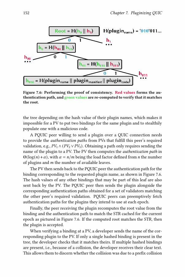
152 Chapter 7. Pluginizing QUIC
Figure 7.6: Performing the proof of consistency. Red values forms the au-thentication path, and green values are re-computed to verify that itmatchesthe root.
the tree depending on the hash value of their plugin names, which makes itimpossible for a PV to put two bindings for the same plugin and to stealthilypopulate one with a malicious code.
A PQUIC peer willing to send a plugin over a QUIC connection needsto provide the authentication paths from PVs that ful�ll this peer’s requiredvalidation, e.g., %+1∧ (%+2∨%+3). Obtaining a path only requires sending thename of the plugin to a PV. The PV then computes the authentication path inΘ(log(=) +U), with U = =/< being the load factor de�ned from = the numberof plugins and< the number of available leaves.
The PV then sends back to the PQUIC peer the authentication path for thebinding corresponding to the requested plugin name, as shown in Figure 7.6.The hash values of any other bindings that may be part of this leaf are alsosent back by the PV. The PQUIC peer then sends the plugin alongside thecorresponding authentication paths obtained for a set of validators matchingthe other peer’s required validation. PQUIC peers can preemptively fetchauthentication paths for the plugins they intend to use at each epoch.
Finally, the peer receiving the plugin recomputes the root value from thebinding and the authentication path to match the STR cached for the currentepoch as pictured in Figure 7.6. If the computed root matches the STR, thenthe plugin is accepted.
When verifying a binding at a PV, a developer sends the name of the cor-responding plugin to the PV. If only a single hashed binding is present in thetree, the developer checks that it matches theirs. If multiple hashed bindingsare present, i.e., because of a collision, the developer receives their clear text.This allows them to discern whether the collision was due to a pre�x collision

7.2. Exchanging Plugins 153
ServerClient
CRYPTO(CHLO(supported_plugins=[monitoring]))
· · ·CRYPTO(SH(plugins_to_inject=[multipath]))
PLUGIN_VALIDATE(multipath, %+1 ∧ (%+2 ∨ %+3))
PLUGIN_PROOF(multipath, �%%+1 , �%%+2 ), PLUGIN(multipath)
Figure 7.7: Example �ow for the exchange of the FEC plugin.
or the PV added a spurious binding.If the PV tree does not contain the hashed binding of a given plugin, its
developer obtains a proof of absence, i.e., an authentication path to the linked-list without the developer’s binding or an authentication path to the constantvalue 2 indicating an empty leaf such that it matches the truncated bits ofH(pluginname).
7.2.4 Exchanging QUIC Plugins
Given the �exibility of QUIC, it is relatively simple to modify it to supportthe exchange of plugins. The QUIC connection establishment packets con-tain QUIC transport parameters such as the maximum number of streams, themaximum packet size or the idle timeout [QUIC-t]. To enable plugin injec-tion, PQUIC proposes two new QUIC transport parameters: supported_-plugins and plugins_to_inject, both containing an ordered list of pro-tocol plugins’ identi�ers. The �rst supported_plugins parameter an-nounces the plugins that a PQUIC peer can inject locally. These plugins arestored inside its local cache. The second plugins_to_inject announcesthe plugins a PQUIC peer would like to communicate to the other peer in or-der to apply them on the running connection. Once the QUIC handshake hascompleted, both peers have a complete view of the available and requestedplugins. Then, there can be two outcomes. Either (0), all plugins requestedfor injection are already available. In this case, they are injected as local plug-ins, as explained in Section 7.1, in the order described by the plugins_to_-inject transport parameter. Else (1), one or more plugins are unavailable lo-cally, they are then transferred as illustrated in Figure 7.7. In this example, theclient announces the support of a monitoring plugin while the server wouldlike to inject a multipath plugin into the client. First, the client announces itsrequired validation formula for missing plugins, hence multipath, with thePLUGIN_VALIDATE frame. Second, the server responds with authentication

154 Chapter 7. Pluginizing QUIC
paths from PVs that ful�ll this formula in a PLUGIN_PROOF frame. The re-quested plugin is then transferred over the plugin stream in PLUGIN frames,akin to the QUIC cryptographic stream. When receiving the remote plugin,the client performs the check of the proof of consistency. Upon success, itstores the plugin in its local cache. Remote plugins are not activated for thecurrent connection, but rather o�ered in subsequent connections as part ofthe locally available plugins. While PQUIC is capable of injecting plugins atany time (as explained in Section 7.1), synchronizing their injection betweentwo hosts raises potential issues. For instance, consider the case of a pluginmodifying the format of an existing QUIC frame, e.g., the multipath pluginadding a Path ID �eld at the beginning of theAck frame. How canQUIC hostsagree when they should expect to parse the Path ID �eld in the incoming Ackframes? We prevent these issues by this conservative choice.
While the exchange mechanisms introduce some overhead, we believe itremains acceptable. The �xed cost of exchanging plugin bytecodes is onlypresent during the �rst connection, as subsequent ones will take advantageof the PQUIC caching system described in Section 7.1.5. Furthermore, if theplugin is not mandatory for the use of the application (e.g., adding the mul-tipath extension to better aggregate the available network links), the pluginexchange does not prevent data from being transmitted over the connection.Indeed, data and plugin streams can be concurrently used thanks to the QUICframe multiplexing.
7.3 Exploring Simple Protocol Tuning
Before digging into large plugins, we �rst consider here simple plugins com-posed of only one pluglet inserted in REPLACE mode modifying speci�c algo-rithms. For this, we �rst implemented a proof-of-concept prototype based onour mp-quic implementation supporting Multipath gQUIC to assess the fea-sibility of our solution. Our plugins are written in C and we use the clangand llvm tools to produce the eBPF bytecode which can be injected insideour QUIC implementation.
To make the mp-quic implementation pluggable, we inserted (i) a map ofplugins for each connection context with a dedicated API to inject code, (ii)an API implementing anchors, testing if a plugin is present to run it and pro-cessing the shared context, and (iii) code integrating the eBPF VM as a library.Notice that this version only integrated the POE (§7.1.1) thanks to the previ-ously presented user-space eBPF VM written in C [IO 18]. This prototype thusdoes not integrate the generic API presented in Section 7.1.3 (as it relies ona ad-hoc, protocol operation speci�c structure stored in the shared memory),but helped to design it.
We use mp-quic to demonstrate that protocol plugins can be pushed in

7.3. Exploring Simple Protocol Tuning 155
Figure 7.8: The network used for the ACK tuning experiment.
an implementation written in a di�erent language and explore multipath usecases. To enable the eBPF VM to interact with mp-quic, we use cgo. Thisstandard Go package allows calling C code from a Go program. However,it requires data to be copied into a particular structure passed to cgo andeventually to the VM.
In the remaining of this Section, we perform our experiments in theMininet environment [Han+12]. We �rst show how a plugin can tune theMultipath QUIC ACK scheduling strategy (§7.3.1). We then demonstrate thedynamic loading of pluglets by limiting the sending rate (§7.3.2). Finally,we detail the overhead of protocol plugins in our prototype implementation(§7.3.3).
7.3.1 Tuning ACK Frame Scheduling
Our �rst multipath use case is a scenario with asymmetric bandwidth shownin Figure 7.8. In this environment, it would be bene�cial to send data over thebottom path and the acknowledgments over the upper one. This is possiblewith QUIC since frames are independent of the packet carrying them in con-trast with Multipath TCP where acknowledgments must be sent on the samepath as data. However, as stated in Chapter 6, changing the acknowledgmentstrategy of Multipath gQUIC can a�ect the performance since latency mea-surements would be a�ected. Protocol plugins can be injected at remote sideto ensure a consistent acknowledgment strategy.
Consider the network shown in Figure 7.8 with a 20 MB bulk download.Sending acknowledgments on the same path as data is not the best strategy,as acknowledgments would saturate the R2-R3 link. With this strategy, Fig-ure 7.9 show that the client needs between 6 and 10 seconds to download the20 MB �le from the server. We then implement a pluglet of 30 lines of codethat attaches to the SelectACKPath operation on the client to force it to sendall acknowledgments on the upper path. Our results show that this strategysigni�cantly reduces the download times as acknowledgments are returnedquickly to the server and they do not saturate the upper link.

156 Chapter 7. Pluginizing QUIC
3 4 5 6 7 8 9 10 11Stream Completion Time (s)
0.0
0.5
1.0C
DF
over
ru
ns
ACK plugin
No plugin
Figure 7.9: When plugin code forces ACK frame sending on the R1-R3 path,the transfer completes quicker.
0 1 2 3 4 5 6 7 8Time (s)
0
5
10
In
stan
tan
eou
s
Th
rou
gh
pu
t[M
B/s]
No plugin
Rate plugins
Figure 7.10: Three plugins, loaded at di�erent times, controlling the rate overan expensive path.
7.3.2 Restricting the Pacing Rate
Our second use case is inspired by smartphones. Recall from Chapters 2 and 3that Multipath TCP enables them to simultaneously use both the Wi-Fi andthe cellular networks. However, many users have volume caps on their cel-lular plans and do not want to use the cellular network for large downloadswhen Wi-Fi is available.
In this situation, the smartphone needs to control the operation of theserver to restrict the bandwidth consumed on the cellular network. However,a server cannot easily infer what is the desired bandwidth cap over a givenpath. We address this problem with a protocol plugin that is pushed by thesmartphone to the server at the beginning of the connection. This plugin isattached to the congestion control mechanism on the server and throttles itscongestion window over the cellular path, but not over the Wi-Fi one. Bywriting only 10 lines of C code, our plugin allows this behavior. Figure 7.10

7.3. Exploring Simple Protocol Tuning 157
eBPF cgo eBPF Preparing Empty struc- Empty struc-code no-op no-op structure ture to cgo ture to eBPF
-25.1 % -4.9 % -6.1 % -8.9 % -21.7 % -21.7 %
Table 7.2: The performance di�erence of mp-quic with the pluginized packetscheduler compared to native Go code.
shows the e�ect of three di�erent plugin versions over a two-path scenariowith 80 Mbps and 50 ms RTT links. The �rst one, injected after the handshake,limits the rate to 3 MB/s. The second one, inserted after three seconds afterremoving the �rst one, caps the speed to 10 MB/s. Finally, the last one, addedafter six seconds after dropping the previous one, constraints the link to 1MB/s. Our results presented in Figure 7.10 con�rm the e�ect of these pluginsand demonstrate that they can be injected at any time on a connection afterthe handshake.
7.3.3 The Cost of Protocol Plugins
The proposed protocol plugins come with a trade-o� between customizationand performance. Two factors in�uence their impact. First, there is a networkoverhead to exchange protocol plugins on a per connection basis. Second,there is some computational overhead to call plugin code instead of nativeone.
Network Overhead. The transmission of the executable bytecode gener-ates additional load on the network. With the eBPF user-space VM used inour prototype, the executable codes are ELF �les containing metadata (sec-tions header, strings table, symbols table,...) in addition to the raw eBPF byte-code. Our two simple use cases presented here introduce plugins requiringonly a few lines of C code, leading to ELF �les of 1 KB and 512 B for theACK scheduling and the pacing rate, respectively. With very simple plugins,this network overhead is negligible for video streaming applications or thedownload of large web pages.
Computational Overhead. Executing the protocol plugins inside a VMprovides portability and isolation, but is slower than native code. Further-more, the interactions with the instrumented implementation can also intro-duce some additional load. To quantify this overhead, we benchmark our mp-quic implementation by measuring the throughput on localhost when trans-ferring 50 MB. This is a standard benchmark used by the quic-go imple-mentation.

158 Chapter 7. Pluginizing QUIC
The packet scheduler is a critical component for multipath proto-cols [Paa+14] and previous works proposed to make it �exible to applicationneeds [Frö+17]. We consider the lowest-latency packet scheduler, both innative Go code — no plugin — and as a plugin. This plugin weights around3 KB for 107 lines of C code. The packet scheduler is a critical element of thesending work�ow, as it is called at each packet transmission occasion. Ta-ble 7.2 indicates that in our mp-quic implementation, this plugin reduces theachieved throughput by 25% compared to its native Go variant. As previouslyexplained, cgo bridges the Go implementation with the eBPF VM. To commu-nicate with the eBPF VM, mp-quic must �rst prepare a structure that exposesthe connection context to the VM. As the core mp-quic implementation cannotpredict which �elds of the connection context will actually be used, it mustput all of them in the structure. This consumes CPU times. If the schedulerin native Go code also �lls such structure, its performance drops by 9%. Thisresult demonstrates the value of proposing an API of getters and setters to theVM. Nevertheless, the main overhead comes from the stack switch inducedby cgo. Its impact depends on the size of the interface structure. Runningthe native Go scheduler with a cgo no-op without any communicated datadecreases the performance by 5%. Doing the same with a 8 KB communicatedstructure lowers the performance by 22%. In such cases, we do not observeany di�erence between cgo and eBPF no-ops. We could mitigate the perfor-mance impact of cgo by using a user-space eBPF VM written in native Golanguage. However, to our knowledge, such software was not available at thetime we made our mp-quic prototype.
7.4 Building Complete Extensions with Plugins
Building on our previous experiences with our early mp-quic prototype, wenow focus on a much more complete implementation of PQUIC based onthe picoquic one [Hui18] written in C. It fully implements all the mech-anisms presented in Section 7.1 as well as the plugin exchange describedin Section 7.2.4. We �rst discuss some implementation details about howwe make picoquic pluginizable (§7.4.1). Then, we describe how we man-aged to fully implement the multipath extensions using only plugins (§7.4.2)and evaluate its performance against a native Multipath QUIC implemen-tation (§7.4.3). This approach enables hosts to provide di�erent multipath-speci�c algorithms depending on the application requirements (§7.4.4). Wealso demonstrate that our approach allows PQUIC hosts to combine orthog-onal plugins (§7.4.5). Finally, we conclude this Section by analyzing the over-head brought by protocol plugins (§7.4.6).

7.4. Building Complete Extensions with Plugins 159
7.4.1 Making the Implementation Pluginizable
While the core ideas of PQUIC have been discussed in Section 7.1, they re-quire a speci�c implementation design that we explain now. In particular,we describe (i) how we seamlessly call protocol operations regardless of theirbehavior being provided by pluglets or not, (ii) how we provide a generic in-terface to pass arguments to the POE, and (iii) how we handle nested protocoloperation calls without any interference.
Refactoring Implementation Functions with Pointer Indirections
A naive solution to make a speci�c part of the implementation customizableby a pluglet is to adopt a similar approach as our early prototype describedin Section 7.3 by inserting explicit checks — if/else — for a POE at speci�ccode locations. Such an approach su�ers from at least two drawbacks. First,it prevents plugins from adding protocol operations that were not alreadypresent in the base implementation. Second, it requires that built-in functionsmust be aware if a pluglet is present or not to run their behavior. The presenceof pluglets should not be the concern of built-in, pluginizable functions.
Instead, our PQUIC implementation replaces native function calls by pro-tocol operations identi�ed by human-readable names. From a concrete view-point, each connection context includes a hash table making the link betweenthe string identi�er and an internal structure representing the protocol op-eration. When a connection is created, the PQUIC implementation registersall the protocol operations. The address of the built-in function is stored inthe internal protocol operation. The awareness of the presence of POEs isthus delegated to this protocol operation structure. When a plugin de�nes anew protocol operation, the PQUIC implementation creates a new entry inthe connection-related hash table, hence achieving the requested design. No-tice that computing the hash of a protocol operation’s identi�er takes time— about 100 `B with our implementation. To mitigate its impact, we pre-compute the hash value at host initialization such that the core implementa-tion can reuse it without further processing.
A Generic Interface for the POE
Distinct protocol operations often require di�erent inputs and outputs. How-ever, our user-space eBPF VM only supports pluglets taking only one argu-ment. In our early mp-quic prototype, we used it to communicate the pointerto a protocol operation speci�c structure containing the �elds of interest. Yet,this sets the issue of a generic interface between the core implementationand POEs, especially when de�ning new protocol operations. In addition,this raises the challenge of memory access management by plugins — as both

160 Chapter 7. Pluginizing QUIC
the content of the structure and the plugin heap should be accessible by thepluglet.
To solve these issues, the only argument provided to the pluglet is anopaque tag referencing the connection context. Although this tag actuallycorresponds to the related structure pointer, the pluglet cannot dereferenceit as it points to a memory area outside its allowed bounds. The pluglet thenuses the provided tag as an argument to the getters and setters to retrieve thevariables of interest. All the values handled by these getters and setters areprotoop_arg_t, which actually correspond to uint64_t. When a pluginwants to access a speci�c structure, it �rst fetches its tag and then uses it inthe structure-dedicated getter and setter. To retrieve the protocol operationarguments, the plugin uses a speci�c connection’s getter with the index cor-responding to the desired input. Similarly, a dedicated setter enables plugletsto communicate output(s) to the caller. Such a design ensures a common in-terface for all plugins while focusing the memory access management onlyto the plugin heap.
Handling Nested Protocol Operation Calls
Because all the codes de�ning the behavior of protocol operations — eitherbuilt-in or provided by a plugin — use the common API to fetch inputs andprovide outputs, there is a need for coordination to avoid interference be-tween di�erent protocol operations. In particular, a pluglet might call anotherprotocol operation before fetching a given input or might generate an outputbefore calling another protocol operation. To keep this isolation between dif-ferent inputs and outputs, our central plugin_run_protoop function savesall the previous inputs and outputs on its stack before preparing the new onesfor the protocol operation to be called. Once it returned, the inputs and out-puts previously stored on the stack are restored and the pluglet continues itsexecution without noticing any change in its inputs or outputs. Notice thatit gets the outputs of the called protocol operation in a structure it used tocall it. In addition to this argument processing, our plugin_run_protoopfunction also checks for protocol operation call loops by setting (when call-ing) and resetting (when returning) a speci�c bit in the protocol operationstructure.
7.4.2 Implementing the Multipath Extensions with Plugins
Protocol plugins can be used to implement various extensions to PQUIC.With less than 100 lines of C code, a PQUIC plugin can add the equivalentof Tail Loss Probe in TCP [Fla+13], or support for Explicit Congestion Noti-�cation [Wes18]. In this Section, we rather focus on the much more complex

7.4. Building Complete Extensions with Plugins 161
Multipath extensions for the QUIC protocol described in Chapter 6 to demon-strate the �exibility and the extensibility of PQUIC. Other use cases have beenconsidered too, we invite the interested reader to look at our SIGCOMM 2019paper for further detail [De +19]. From a concrete viewpoint, our Multipathplugin consists in 26 pluglets injected in 14 distinct protocol operations. Fig-ure 7.11 illustrates most of the injected pluglets and their insertion point. Tounderstand the design of our Multipath plugin, let us consider several com-mon code paths.
First, upon reception of a packet containing frames, a PQUIC implemen-tation parses its header mentioning the Connection ID. Because the basepicoquic implementation supports connection migration (but not the si-multaneous usage of multiple paths), it embeds the notion of path. Sincethe Connection ID implicitly indicates to which incoming path the packetwas sent, we injected a pluglet in REPLACE mode to the get_incoming_-
path protocol operation as illustrated in Figure 7.11f. After decrypting thepacket, the PQUIC implementation starts decoding each frame along withthe related connection and incoming path contexts. QUIC frames always startwith their Type variable-length integer �eld. This type acts as an identi�erof the decoded frame. We split the frame decoding process into two protocoloperations as pictured in Figure 7.11a. First, the parse_frame one interpretsthe frame’s raw bytes and returns a C frame-speci�c structure containing allthe frame’s �elds. Second, the process_frame one takes the output of theparse_frame protocol operation as input and performs actions depending onthe actual content of the frame. This distinction between the parsing andthe processing of frames — although not strictly required — aims at keep-ing focused protocol operations to avoid very large and complex pluglets. Inaddition, since our implementation stores sent packets as raw bytes, it re-quires parsing again its frames without doing any further processing. In ourcurrent Multipath plugin, we implemented ADD ADDRESS, ACK and NEWCONNECTION ID frames. Notice that the two last ones, which are actuallysmall modi�cations of the original ones, are implemented with their own type(MPACK and MP NEW CONNECTION ID). This induces the addition of twopluglets (one in parse_frame, the other in process_frame) for each frame.
While the processing of the ADD ADDRESS and MP NEW CONNEC-TION ID frames does not involve additional protocol operation calls, the oneof the MPACK frames includes other ones. When receiving an acknowledg-ment, the host can estimate the network latency. Therefore, the processingof MPACK frames requests the update_r� protocol operation. The Multipathplugin inserts a pluglet in REPLACE mode to make path-aware RTT estima-tions. Then, it handles the acknowledged packets through the process_ack_-
range protocol operation. This one �rst adapts the range that it communicatesthrough its MPACK frames through the process_ack_of_ack_frame protocol

162 Chapter 7. Pluginizing QUIC
decode_frame parse_frame [MPACK] process_frame [MPACK] update_r process_ack_range
(a) Handling the reception of a frame (MPACK case).process_ack_range process_ack_of_ack_frame dequeue_retransmit_packet notify_frame[MPACK]
(b) Processing an ACK range (continuation of Figure 7.11a).
prepare_packet schedule_frames schedule_path predict_header_length write_frame[MPACK]manage_paths
(c) Sending a QUIC packet.
Figure 7.11: Themodi�ed code path to include themultipath extensions onlywith plugins. Added protocol operations and parameters are shown in greenwhile pluglets inserted in REPLACE and POST modes are respectively rep-resented in red and blue.

7.4. Building Complete Extensions with Plugins 163
prepare_packet set_next_wake_time
(d) Sending a QUIC packet (continuationof Figure 7.11c).
create_packet_header get_destination_connection_id
(e) Creating an header of a packet to besent.
incoming_packet get_incoming_path
(f) Identifying the receive path of an in-coming packet.
connection_state_changed
(g) Being noti�ed that the connectionstate is ready.
Figure 7.11: Themodi�ed code path to include themultipath extensions onlywith plugins. Added protocol operations and parameters are shown in greenwhile pluglets inserted in REPLACE and POST modes are respectively rep-resented in red and blue.
operation. Under the hood, this last operation parses again the sent pack-ets’ raw bytes — hence calling parse_frame — and is updated by a pluglet tomake it aware of MPACK frames. Finally, based on the received ACK range,the implementation can go through its sent packets bu�er thanks to the de-
queue_retransmit_packet protocol operation to determine if the packet canbe freed or otherwise its content should be retransmitted. In any case, ourPQUIC implementation informs plugins about the (non) delivery of their re-served frames through the notify_frame protocol operation. Again, a plugletin REPLACE mode is inserted for each implemented frame.
Now that we completed the packet reception’s code path, we focus onthe sending one shown in Figures 7.11c and 7.11d. At some point, the code�ow calls the prepare_packet protocol operation which itself requests theschedule_frames one. It determines which frames will be included in thenext packet to be sent. Because the base PQUIC implementation only uses asingle path, our Multipath plugin injects a pluglet in REPLACE mode allow-ing the usage of others paths. In particular, we dedicate the selection of thepath to a new protocol operation schedule_path. With such decomposition,PQUIC hosts can change their path selection algorithm without consideringthe frames that will be put on the selected outgoing path. The Multipath plu-gin also introduces another protocol operation, manage_paths, associatingthe available paths to speci�c 4-tuples. In our current version, the sched-
ule_path protocol operation always calls the manage_paths one, but it canalso be extended to listen to speci�c events, such as the loss of an IP address.

164 Chapter 7. Pluginizing QUIC
Once the sending uni�ow has been selected, the schedule_frames protocoloperation estimates the available packet space for frames by calling the pre-
dict_header_length one. As each sending uni�ow has a distinct ConnectionID, with possibly di�erent lengths, we put in a pluglet in that protocol oper-ation. Once a frame has been selected for sending, it calls the write_frame
protocol operation with its type as a parameter. Again, each of our four im-plemented frames has its own dedicated pluglet. Once the content of thepacket has been determined, the prepare_packet protocol operation relies onthe set_next_wake_time one to determine when the timer should �re. Weadapt its operations with a pluglet to make it aware of the di�erent avail-able paths. Finally, just before sending the packet to the network, it requireswriting its header through the create_packet_header protocol operation. Aseach sending uni�ow has a di�erent Destination Connection ID, we insert apluglet at the get_destination_connection_id protocol operation, as shownin Figure 7.11e. Notice that since picoquic actually sends packets usingthe sendmsg call — �lling its auxiliary data with the desired packet’s 4-tuplefrom the path context — there is no need for the Multipath plugin to tweak it.
The last piece of our Multipath plugin resides in knowing when PQUIChosts can start using several paths. As explained in Chapter 6, PQUIC peersmust �rst complete the handshake before beginning multipath operations.This is why we insert a last pluglet in POST mode to the connection_state_-
changed protocol operation as pictured in Figure 7.11g. Once the connectionbecomes ready, our pluglet triggers the sending of both ADD ADDRESS andMPNEWCONNECTION ID frames, hence enabling the use of multiple paths.
Together, all these pluglets form a PQUIC plugin of 2750 lines of C codethat provides basic multipath capabilities following the requirements enu-merated in Chapter 6. Our plugin supports the exchange of Path ConnectionIDs and host IP addresses. It then associates a sending Uni�ow ID betweeneach pair of host addresses, similar to the full-mesh path manager used byMultipath TCP. We implement both the round-robin and the lowest latency�rst schedulers.
7.4.3 Evaluating the Multipath Plugin
We evaluate the performance of our Multipath plugin in a lab equipped withIntel Xeon X3440 processors, 16 GB of RAM and 1 Gbps, running Linux kernel4.19 and con�gured as shown in Figure 7.12. The links R1-R3 and R2-R3 arecon�gured using netem [Hem+05] to add transmission delays and using htbto limit their bandwidth. One-way delay d is expressed in milliseconds andbandwidth bw in Mbps.
To evaluate our plugin in a wide range of environments, we reuse the ex-perimental design approach [Fis35]. We de�ne ranges on the possible values

7.4. Building Complete Extensions with Plugins 165
{d1 , bw
1 }
{d2, bw2
}
Client
R1
R2
R3 Server
Figure 7.12: Network topology used for experiments.
10KB 50KB 1MB 10MB0.5
1.0
1.5
2.0
Spee
dup
ratio
mp-quic
10KB 50KB 1MB 10MB
Multipath plugin
File size
Figure 7.13: Over two symmetric network paths, multipath tends to completetransfers twice faster than single-path.
for the parameters presented and use the WSP algorithm [SCS12] to broadlysample this parameter space into 139 points. Each parameter combination isrun 9 times and the median run is reported. This mitigates a possible bias inparameter selection and gives a general con�dence in the experiment results.We use the parameter range {d1 ∈ [2.5, 25] ms, bw1 ∈ [5, 50] Mbps, d2 =
d1, bw2 = bw1}, and assume that both links have similar bandwidth and delaycharacteristics. Note that when links are lossless, congestion-induced lossescan still be observed due to the limited bandwidth and router bu�ers, set tothe bandwidth-delay product. Our plugin is cached on both the client and theserver.
For both single path and multipath settings, we record the time between aGET request issued by the client and the reception of the last byte of the serverresponse. We then compute the ratio of the single path completion time overthe multipath one to obtain the speedup ratio. We observe its evolution withthe size of the requested �le and compare it with the ratio obtained using thenative mp-quic implementation presented in Chapter 5. Figure 7.13 shows thatwith small �les, there is little gain in using two paths. This is not surprisingsince each path is constrained by its initial congestion window. Notice thatthe initial path window of mp-quic (32 KB), inherited from quic-go [CS18],

166 Chapter 7. Pluginizing QUIC
is twice the default one of PQUIC (16 KB). This explains the small speedupgain of our plugin on 50 KB �les. With larger �les, both mp-quic and ourMultipath plugin e�ciently use the two available paths. The speedup ratioof both the native mp-quic and our Multipath plugin tends to reach 2 with 10MB �les.
7.4.4 Adapting the Multipath Plugin to Interactive Use Cases
Providing tuned multipath-speci�c algorithms to dedicated use cases is oneof the key motivations to distribute the Multipath extensions as plugins. Con-sider the case of packet schedulers. When network paths exhibit similar de-lays and bandwidths, a simple round-robin scheduler works well when per-forming bulk transfers. Once di�erent delays are observed, a lowest-latency�rst one is more suitable. However, when the application requires a low-latency service within a wireless environment, solutions such as MultiMob(§3.3) are more appropriate.
Our PQUIC approach enables hosts to use all these di�erent schedulingstrategies without modifying their implementation. From a concrete view-point, our Multipath plugin is split into two parts. The �rst one containsthe core pluglets providing the support for the extensions. The second oneconsists in the multipath-speci�c algorithms — here the path manager andthe packet scheduler. While the �rst part always contains the same pluglets,a host can select the most appropriate multipath-speci�c algorithms in theplugin it negotiates with its peer.
To demonstrate the bene�ts of this approach, let us reconsider the sce-nario presented in Section 5.2.5 where a delay-sensitive application gener-ating request/reponse tra�c loses its lowest latency path (15 ms RTT) after3 seconds (using tc netem loss 100%). We evaluate two variants of theMultipath plugin. The �rst one embeds the lowest latency �rst path schedulerat both client’s and server’s sides and prefers using the initial network path(15 ms RTT) over the additional one (25 ms RTT). The second variant stilluses this lowest latency �rst scheduler at client’s side but makes the serverfollow the client’s scheduling decisions similar to the MultiMob’s server-side packet scheduler (§3.3.1). In practice, it records the remote address ofthe last received packet and forces the server to send the next packet on asending path reaching the given remote address. Each 1400-byte request sentevery 400 ms triggers a 750-byte response. Unlike our previous experiments,each request/response takes place in its own stream, meaning that a delayedresponse does not impact subsequent requests. Notice that our Multipath plu-gin does not implement the PATHS frame, i.e., a host noticing a path failuredoes not advertise it to its peer.
We perform our experiments in the same lab as in Section 7.4.3. Fig-

7.4. Building Complete Extensions with Plugins 167
0 2 4 6 8 10 12 14Sent Time [s]
0
50
100
150
200A
pp
lication
Perceived
Delay
[m
s]
RTT Scheduler
Figure 7.14: A server-side packet scheduler following the client’s decisionsprevents the server from su�ering a RTO too.
ure 7.14 indicates that before the loss event, the two experiments uses thelowest latency network path. Notice that the initial request observes a re-sponse delay of 20 ms because the client still limits its packet size to 1252bytes to avoid fragmentation as it did not send a path MTU discovery packetyet. Hence, the request is split into two packets. Since the latency schedulerwants to test the additional path, the complete request arrives at the serverafter 12.5 ms, which replies on the fastest path5. When the loss event occurs,it takes 50 ms for the client to notice that the preferred path is potentiallyfailed and duplicate the frames over the additional path. While the server-side scheduler follows the last client’s decision and directly replies on theadditional path, the lowest latency �rst scheduler also experiences a RTO atserver side after 50 ms. Then, both Multipath variants continues the tra�cover the working additional path.
7.4.5 Combining Orthogonal Plugins
Given the isolation provided by PQUIC, it is possible to load di�erent pluginson a given PQUIC implementation provided that they do not both replace asame protocol operation. To demonstrate this design �exibility, we show howour Multipath plugin can be injected together with another one providing un-reliable messages. This last plugin relies on the EXTERNAL anchor presentedin Section 7.1.4 to let the application request the unreliable delivery of data.Their combination typically suits a QUIC-based Multipath VPN application.
5The server-side scheduler also behaves the same way but for di�erent reasons. At thetime it fully receives the �rst request, the additional path is not validated yet, only leaving thefastest one for the response.

168 Chapter 7. Pluginizing QUIC
0.5 0.6 0.7 0.8 0.9 1.0 1.1 1.2DCT in/out
0.000.250.500.751.00
CDF
1.5 KB10 KB50 KB1 MB10 MB
Figure 7.15: Download Completion Time ratio of TCP inside and outside amultipath client-server tunnel.
Benchmark Native eBPF JIT-compiled eBPF InterpretedSimple loop 839 ms 1706 ms 17000 ms
Get / Set 844 ms 5336 ms 40150 ms
Table 7.3: Execution time for the micro-benchmarks (median over 3 runs).
We evaluate the performance of combining these two plugins in the samenetwork scenario explored in Section 7.4.3. Our scenario creates Linux tun-nel interfaces at both client and server sides to carry IP datagrams inside aPQUIC connection. We measure the ratio of Download Completion Time(DCT) when running a single TCP Cubic �le transfer inside and outside theMultipath VPN tunnel for di�erent �le sizes.
As expected, we do not observe any bene�t in using multipath for tun-neling a short TCP transfer, as pictured in Figure 7.15. However, as �le sizegrows the bene�ts of using multiple paths become clear. By spreading thetra�c over the two symmetric paths, our combined plugins reach a DCT ra-tio that tends to 0.55. This shows that our plugins enable TCP to aggregateboth paths’ bandwidth without being aware of the multipath usage.
7.4.6 Plugin Overhead
The balance between �exibility and performance is a classical trade-o�.Google and the IETF have decided to run QUIC over UDP despite the factthat Google measured that "QUIC’s server CPU utilization was about 3.5 times
higher than TLS/TCP " [IS18]. The performance gap between TCP and UDPhas since been slightly reduced, but UDP remains slower [BD18]. As PQUICdelegates the execution of the plugins to the POE, there is a processing over-head due to the Just-In-Time (JIT) compilation, the run-time veri�cations per-formed by our monitor at each memory access, and the utilization of the APIto safely access PQUIC state variables.
Executing code in the POE is less e�cient than running native code. Toassess this, we write a simple for loop performing at each iteration a sum,

7.4. Building Complete Extensions with Plugins 169
Plugin G̃ Goodput f/G̃ G̃ Load TimePQUIC, no plugin 1104.2 Mbps 3.8% 0.0 ms
Monitoring (0) 1037.3 Mbps 4.6% 6.35 msMultipath 1-path (1) 756.6 Mbps 3.1% 8.28 ms
0 and 1 714.2 Mbps 4.4% 13.00 ms
Table 7.4: Benchmarking plugins over 10Gbps links (20 runs).
a multiplication and a division on a 64-bit integer and evaluate it on a lap-top running on a Intel Core i7-4810MQ CPU @ 2.80GHz with 16 GB of RAM.We implement it both as a plugin and in native C code and run the loop onebillion times. Table 7.3 indicates that the POE is twice slower than nativecode. Such overhead could probably be mitigated by using a more optimizedVM with a smarter JIT compiler. We also evaluate the impact of our get/setAPI by writing a for loop getting and setting two integer �elds at each iter-ation. Running the loop 500 millions times, we observe that our get/set APIis six times slower compared to direct memory accesses. Notice that in allour experiments, we consider JIT-compiled bytecode. Our user-space eBPFVM also enables us to run it in interpreted mode. However, on a computa-tionally intensive benchmark, the interpreted mode is ten times slower thanJIT-compiled one.
To observe this performance impact in more bandwidth-intensive envi-ronments, we benchmark our PQUIC implementation by measuring the com-pletion time of a 1 GB download between two servers with 10 Gbps NICs.We initially performed our analysis with our lab described in Section 7.4.3,but we noticed that the main CPU overhead came from the TLS encryptionand decryption of packets. This is because our initial processors — Intel XeonX3440 — do not provide hardware support for AES encryption. Hence, werelaunch our experiments with servers equipped with Intel Xeon E5-2640 v3CPUs. These bene�t from newer instruction sets — notably AES-NI — andallow us to focus on the plugin execution overhead. Note that our PQUIC im-plementation is single-threaded and thus does not bene�t from the additionalCPU cores.
Table 7.4 reports the median achieved goodput, its relative variance andthe plugin loading time for each plugin. PQUIC achieves a median goodputof 1104.2 Mbps. This low performance compared to TCP is partly due to thefact that picoquic, the implementation on which PQUIC is based, has notbeen optimized yet for performance. Indeed, as the QUIC speci�cation wasstill evolving when we built our implementation, there was limited interest indeeply optimizing a QUIC implementation at that stage. Comparing PQUICto the version of picoquic we based our work on could allow measuring

170 Chapter 7. Pluginizing QUIC
the impact of adding our approach to a QUIC implementation. However, thisis technically challenging, as our PQUIC version also contains performanceand bug �xes to picoquic6. There is thus no picoquic version match-ing the current state of PQUIC. We could also compare the latest version ofpicoquic with PQUIC. Nevertheless, both picoquic and the QUIC speci�-cation itself have substantially evolved during our work, adding many degreesof freedom that would confuse the performance evaluation.
Since QUIC encrypts everything, it is di�cult for network operators totroubleshoot their connections. We propose a protocol plugin [De +19] —consisting of 500 lines of C code spread into 14 pluglets — that attaches byte-codes at strategic PRE and POST anchors to monitor the state of runningPQUIC connections. When evaluating this monitoring plugin, we observe agoodput reduction of 7% which matches the additional 8% CPU instructionsexecuted. We also observed a 10% increase of TLB load misses caused by thecontext switches between PQUIC codes and the POEs. Given that the moni-toring code complexity is low, these results illustrate the overhead of addingseveral pluglets within the critical path.
The benchmark of the Multipath plugin over a single path achieves a me-dian goodput of 756.6 Mbps. Several factors explain this reduction. First, theacknowledgments are created by the plugin usingMPACK frames, which con-stitutes a signi�cant part of the client execution time. Second, the Multipathplugin provides a path manager and a path-aware frame scheduler. This addsseveral new protocol operations into the packet processing code path.
Combining both the monitoring and the Multipath plugins results in a6% goodput reduction compared to multipath only. This demonstrates thatplugins with orthogonal features are e�ciently combined using PQUIC.
Inserting plugins takes time, as described in the last column of Table 7.4.This time is proportional to the number of inserted pluglets and their com-plexity. The instantiation of POEs (between 4 and 7 ms) is the major contrib-utor to this loading time. Note that this overhead is only present when thereis no cached plugin available. If the host previously loaded the plugin in acompleted connection, it can reuse its POEs as described in Section 7.1.5 toload the plugin in less than 30 `s.
Plugins can be exchanged between PQUIC peers over the network as de-scribed in Section 7.2.4. To limit the exchange overhead, we rely on a ZIPcompression scheme to transfer plugins. We take advantage from the factthat pluglets from a given plugin can contain duplicate code from commonfunctions. Compressing the Multipath plugin reduces that exchanged over-head from 138 KB (plain ELF �les) to 40 KB (compressed ones). Assumingthe plugin exchange starts at the beginning of the connection with an initial
6Actually, our current version of PQUIC achieves higher goodput than the original versionof picoquic we base our work on.

7.5. Validating Plugins 171
congestion window of 16 KB, it requires 2 RTTs to be exchanged.
7.5 Validating Plugins
As explained in Section 7.2, PQUIC peers can request proofs of the validityof protocol plugins when receiving them over a QUIC connection. The val-idation is carried out by the Plugin Validators. These validators can apply arange of techniques, from manual inspection, privacy checks [Ege+11; Li+15],to fuzzing [PAJ18] or using formal methods [MZ19] to validate the pluginssubmitted by developers. Formal methods are attractive because they enablevalidators to provide strong proofs for network protocols [Bis+05; BBK17;Chu+18].
A very important property for any code is its (correct) termination. If aprotocol plugin would be stuck in an in�nite loop with some speci�c input,then it would obviously be unsafe to use it in a PQUIC implementation. Todemonstrate the possibility of using formal techniques to validate protocolplugins, we used the state-of-the-art T2 [CPR06; BK19] automated termina-tion checker. T2 has been extended to handle a large fragment of Compu-tational Tree Logic (CTL) [Coo+07; CKV11]. Verifying CTL reduces to anextended termination proof of the program combined with CTL informationin states. Therefore, we focus here on the termination property.
Using the appropriate tools [Khl+15; KG+19], we checked the terminationof our Multipath pluglets by compiling their C source code to T2 programs.The T2 prover assumes the termination of external functions, i.e., functionsof the PQUIC implementation available through the POE. On the 26 plugletscomposing the Multipath plugin, we managed to prove the termination of 23of them. To obtain those proofs, we had to slightly modify the source codeof some pluglets to ease the proof process. For example, we added an explicitsize to NULL-terminated linked lists and used it to bound the loops iteratingover them. The three remaining multipath pluglets could not be proven dueto their complexity. It seems that T2 badly handles codes containing multiplenested (bounded) loops. Since T2 can export its termination proofs in �les,these could be attached to the plugins to be the proof-carrying code proposedby Necula [Nec02]. However, given the size and complexity of these proofs, itis unreasonable to expect a PQUIC implementation to download and processthem when loading plugins.
7.6 Related Works
Improving the �exibility of networks is a topic widely studied in the litera-ture. In the late nineties, active networks [TW96; Ten+97] were proposedas a solution to bring innovation inside the network. Various techniques

172 Chapter 7. Pluginizing QUIC
were proposed to place bytecode inside packets so that routers could exe-cute it while forwarding them. PLAN [Hic+98], ANTS [WGT98] and routerplugins [Dec+98] are examples of such active techniques. Interest in activenetworks slowly decreased in the early 2000s [Cal06], but Software De�nedNetworks [McK+08] and P4 [Bos+14] can be considered as some of their suc-cessors.
Most of the work on active networks focused on the network layer andonly a few researchers addressed the extensibility of the transport protocols.CTP [WHS01] is a transport protocol that is composed of various micro-protocols that can be dynamically combined at run-time through the Cac-tus [Hil+99] system. STP [Pat+03] enables the utilization of code written inCyclone [Jim+02] to extend a TCP implementation. icTCP [GAA04] exposesTCP state information and control to user-space applications to enable themto implement various extensions. To our knowledge, these techniques havenot been deployed. In comparison, we believe our approach can be deployedat large scale as it relies on QUIC which prevents middlebox interference andenables a safe exchange of protocol plugins. Our Multipath plugin goes be-yond the extensions proposed for STP and icTCP. CCP [Nar+18] provides aframework to write congestion control schemes in transport protocols in ageneric way. Although we did not explore it in this Chapter, a new conges-tion controller could easily be implemented as a protocol plugin.
To deploy protocol plugins, we design a secure plugin management sys-tem that bares similarities to Certi�cate Transparency [rfc6962]. Our MerklePre�x Tree construction has the major di�erence that plugin developers donot have to scan the entire tree in order to detect spurious plugins linked totheir owned name, but only the branches in which their plugins lie.
Our Plugin Operating Environment is based on a simple user-space im-plementation of the eBPF VM [Fle17; IO 18]. Other execution environmentsthat provide built-in memory checks such as CHERI-MIPS [Woo+14] or We-bAssembly [Haa+17] could be valid alternatives to our POE. Evaluating theirrelevance in the protocol plugin context would be an interesting future work.
7.7 Discussion
Extending the behavior of client-side protocol implementations is di�cult.First, deploying client updates can take several months or even years. Sec-ond, it remains unpractical to tune a protocol implementation when connec-tions require very di�erent services. Currently, experimental QUIC exten-sions such as mp-quic [DB17a] and QUIC-FEC [MDB19] are implemented assource code forks. Updating the base QUIC protocol and combining these ex-tensions impose a signi�cant engineering and maintenance burden, which iscurrently only a�ordable by large Internet companies. We envision PQUIC

7.8. Conclusion and Future Work 173
implementations to be both simple and stable, providing connection-speci�cextensions through plugins. PQUIC could enable developers to focus on oneimplementation interface while still supporting very di�erent implementa-tion’s internal architectures, such as zero-copy and partial hardware o�oad.
Through its plugins, PQUIC provides quick deployments of extension pro-totypes. Still, the bene�ts of plugins for complex standardized extensions dono fade. For instance, while the Multipath speci�cation describes its wire for-mat, both the packet scheduling and path management algorithms dependon the application. Whereas server implementations would likely providebuilt-in support of the Multipath extension for better performance, PQUICprovides more �exible tuning at client side than a simple on/o� extensionswitch. These algorithms could be pushed by the server itself.
7.8 Conclusion and Future Work
Extensibility is a key requirement for many protocol designs. We leveragethe unique features of QUIC to propose a new extensibility model that wecall Pluginized QUIC (PQUIC). A PQUIC implementation is composed of a setof protocol operations which can be enriched or replaced by protocol plugins.These plugins are bytecodes executed by a Protocol Operating Environment(POE) that ensures their safety and portability. The plugins can be dynami-cally loaded by an application that uses PQUIC or received from the remotehost thanks to our secure plugin management system. We demonstrate thebene�ts of this approach by implementing the Multipath extensions to QUICexclusively with plugins.
This new protocol extensibility model opens several directions for futurework. First, a similar approach could be used for other networking protocolsin both the data place and the control plane [Wir+19]. Second, new tech-niques ensuring the implementation conformance to protocol speci�cationscould be explored. These could leverage the PQUIC interface to assess that aplugin composition is correct. A third direction would be to revisit how wedesign protocol robustness [RBP19].
Another direction would be to develop new veri�cation techniquesadapted to pluginized protocols. While our POE detects and prevents the ex-ecution of a range of incorrect and malicious programs, there remain areas ofimprovements in the domain of static eBPF veri�cation techniques [Ger+19].
Finally, PQUIC could be the starting point for the next version of QUIC.This would require the IETF to also specify protocol operations to ensurethe inter-operability of plugins among di�erent implementations. To achievethis, one must identify the minimal core protocol operations required. Thisset should be simple enough to allow very di�erent implementations, hav-ing possibly very speci�c internal architectures such as zero-copy support, to

174 Chapter 7. Pluginizing QUIC
interoperate. Instead of adding more and more features to a monolithic im-plementation, developers could leverage the inherent extensibility of a plug-inized protocol to develop over a simple set of kernel features that are easyto extend.

Conclusion 8Over time, the application requirements have evolved. While the Inter-
net was initially designed to remotely access terminals and exchange bulk�les between computers, it now serves very diverse functions such as voice-activated applications and video streaming. In addition, the rise of mobiledevices motivated the support of multiple paths in transport protocols. Yet,protocol implementations are often optimized for speci�c needs and they typ-ically lack of �exibility to new use cases.
This thesis tackled these issues by exploring how we can make multi-path transport protocols �exible to di�erent application requirements. First,we performed in Chapter 2 two di�erent measurement campaigns evaluatingthe performance of Multipath TCP on smartphones. The �rst one focused onthe implementation in the Linux kernel and observed the tra�c generated byreal users using unmodi�ed Android applications through a Multipath TCP-enabled proxy. While this setup enables smartphones to simultaneously useboth Wi-Fi and cellular networks, only a few connections actually take ad-vantage of these multiple paths, the other ones generating network overheadwithout sending useful data on additional paths. Nonetheless, we showedthat connections that survived from the loss of their initial path represent aconsequent fraction of connections using multiple paths. To further inves-tigate user mobility, we performed as second measurement campaign basedon the iOS implementation. We developed a speci�c application generatingactive measurements in both stable and mobile conditions. In particular, werevealed that the handover process from the Wi-Fi network to the cellular oneis not abrupt, i.e., Multipath TCP simultaneously uses both wireless networksto handle such mobile situations. Still, with user motion there remains roomfor improvement in terms of application-perceived latency.
Then, based on our previous �ndings, we presented in Chapter 3 how wecan tune Multipath TCP to better �t latency-sensitive applications under de-vice mobility while meeting user’s expectations in terms of cellular networkusage. Our solution consists in three parts: (i) a server-side packet sched-uler following the client’s last decisions; (ii) a path-manager creating cellularsub�ows when noticing a bad primary network; and (iii) protocol additionsto detect idle paths and to quickly create additional sub�ows. Our evalua-tion assessed that our tuned Multipath TCP achieves reasonable application-
175

176 Chapter 8. Conclusion
perceived latency while limiting the cellular network overhead. However, dueto deployment and technical constraints, our measurements with real userswere limited to a few devices. Also, the overall implementation e�ort wasquite large compared to their actual bene�ts.
To get rid of both kernel-space and TCP constraints, we considered theQUIC protocol and proposed an initial multipath design in Chapter 5. Com-pared to MultipathTCP, our proposal is cleaner and simpler to deploy at large-scale. By following an experimental design approach, we evaluated bothMultipath TCP and Multipath gQUIC in a broad range of emulated networkscenarios. In lossless networks, we obtained similar results for both MultipathTCP and Multipath gQUIC. Thanks to its better loss signaling, QUIC still ben-e�ts from the usage of multiple paths exhibiting losses, unlike TCP. We thenextended our evaluation to real wireless networks and con�rmed that the per-formance of Multipath TCP and Multipath gQUIC are similar. Nonetheless,our experience with real networks pointed out some limitations in that initialdesign. In Chapter 6, we reconsidered the Multipath extensions for the QUICprotocol to address all the previously raised concerns. While being more de-ployable that the initial design, our new one also takes into account networkasymmetries. Our in-lab experiments con�rm that in such networks, our im-proved design provides higher bene�ts than the initial one.
Finally, we proposed in Chapter 7 to completely revisit how transportprotocols are speci�ed and implemented. To make them fully extensible, weproposed that pluginizable protocol implementations provides a �exible APIto their serving applications. Hosts can extend their protocol behaviors by in-jecting protocol plugins on a per-connection basis. These can be exchangedto the peer over the QUIC connection. We demonstrated that our Multipathextensions can be provided only with plugins and showed that we can achievesimilar performance than a native Multipath QUIC implementation. We envi-sion the case where pluginizable client implementations can be �nely tunedby protocol plugins served by native server implementations. Such an ap-proach would make transport protocols fully �exible to the application re-quirements.
Open Problems
This thesis opened several directions for future research. First, our Multi-pathTester application provides an opportunity to collect multipath proto-cols measurements at a large scale thanks to the iOS support of MultipathTCPand the Multipath QUIC implementation bundled by the application. For thesake of fairness, we shipped a Multipath QUIC packet scheduler similar tothe one of iOS Multipath TCP in interactive mode. Thanks to the �exibilityof Multipath QUIC, it would be possible to explore other multipath-speci�c

177
algorithms or even explore other QUIC extensions, such as Forward ErasureConnection.
Second, while MultiMob is an adaptation of Multipath TCP, some of itsideas can be applied to Multipath QUIC as well. In particular, we could con-sider the break-before-make path management approach to Multipath QUICand how the oracle could be adapted to monitor QUIC �ows instead of TCPones.
Third, the new design of Multipath QUIC explicitly takes into accountthe network asymmetry to use unidirectional paths. This motivates researchworks about one-way path characteristic estimations — such as one-way de-lay — to perform cleverer packet scheduling.
Last but not least, we believe that our PluginizedQUIC work opens severalfollowup works on its own. A �rst direction would apply the proposed exten-sibility model to other protocols, possibly at other layers than the transportone. A second direction would be to explore new veri�cation techniques toassess that plugins ful�ll speci�c safety properties. A third direction wouldbe to identify and specify the core operations of PQUIC— and possibly in-cluding an advanced permission model — such that any protocol plugin canseamlessly work regardless of the PQUIC implementation.


Bibliography
[gQUIC] R. Hamilton, J. Iyengar, I. Swett, and A. Wilk. QUIC: A UDP-
Based Secure and Reliable Transport for HTTP/2. Internet-Draftdraft-hamilton-early-deployment-quic-00. July 2016.
[MPTCPlk] C. Paasch, S. Barre, et al. “Multipath TCP in the Linux Kernel”.http://www.multipath-tcp.org. 2019.
[QUIC-14] J. Iyengar and M. Thomson. QUIC: A UDP-Based Multiplexed
and Secure Transport. Internet-Draft draft-ietf-quic-transport-14. Work in Progress. 2018. 129 pp.
[QUIC-c] A. Langley and W.-T. Chang. “QUIC Crypto”. Dec. 2016.
[QUIC-inv] M. Thomson. Version-Independent Properties of QUIC. Internet-Draft draft-ietf-quic-invariants-07. IETF Secretariat, Spetem-ber 2019.
[QUIC-t] J. Iyengar and M. Thomson. QUIC: A UDP-Based Multiplexed
and Secure Transport. Internet-Draft draft-ietf-quic-transport-27. IETF Secretariat, Feb. 2020.
[rfc1195] R. Callon. Use of OSI IS-IS for routing in TCP/IP and dual envi-
ronments. RFC 1195. Dec. 1990. doi: 10.17487/RFC1195.
[rfc1323] V. Jacobson, R. Braden, and D. Borman. TCP Extensions for HighPerformance. RFC1323. Fremont, CA, USA: RFC Editor, May1992.
[rfc1889] R. Frederick, S. L. Casner, V. Jacobson, and H. Schulzrinne. RTP:A Transport Protocol for Real-Time Applications. RFC 1889. Jan.1996. doi: 10.17487/RFC1889.
[rfc1958] B. Carpenter (Ed.) Architectural Principles of the Internet. RFC1958 (Informational). RFC. Updated by RFC 3439. Fremont, CA,USA: RFC Editor, June 1996. doi: 10.17487/RFC1958.
[rfc2018] S. Floyd, J. Mahdavi, M. Mathis, and D. A. Romanow. TCP Se-
lective Acknowledgment Options. RFC 2018. Oct. 1996. doi: 10.17487/RFC2018.
[rfc2328] J. Moy. OSPF Version 2. RFC 2328. Apr. 1998. doi: 10.17487/RFC2328.
179

180 BIBLIOGRAPHY
[rfc2460] B. Hinden and D. S. E. Deering. Internet Protocol, Version 6 (IPv6)Speci�cation. RFC 2460. Dec. 1998. doi: 10.17487/RFC2460.
[rfc2582] T. Henderson and S. Floyd. The NewReno Modi�cation to TCP’s
Fast Recovery Algorithm. RFC 2582. Apr. 1999. doi: 10.17487/RFC2582.
[rfc2960] R. R. Stewart, Q. Xie, K. Morneault, C. Sharp, H. J.Schwarzbauer, T. Taylor, I. Rytina, M. Kalla, L. Zhang, and V.Paxson. Stream Control Transmission Protocol. RFC2960. RFC.Fremont, CA, USA: RFC Editor, Oct. 2000.
[rfc3022] K. B. Egevang and P. Srisuresh. Traditional IP Network Address
Translator (Traditional NAT). RFC 3022. Jan. 2001. doi: 10 .17487/RFC3022.
[rfc3168] K. K. Ramakrishnan, S. Floyd, and D. L. Black. The Addition of
Explicit Congestion Noti�cation (ECN) to IP. RFC 3168. RFC. Up-dated by RFCs 4301, 6040, 8311. Fremont, CA, USA: RFC Editor,Sept. 2001.
[rfc4271] Y. Rekhter, S. Hares, and T. Li. A Border Gateway Protocol 4
(BGP-4). RFC 4271. Jan. 2006. doi: 10.17487/RFC4271.
[rfc4960] R. Stewart (Ed.) Stream Control Transmission Protocol. RFC 4960(Proposed Standard). RFC. Fremont, CA, USA: RFC Editor, Sept.2007. doi: 10.17487/RFC4960.
[rfc5246] T. Dierks and E. Rescorla. The Transport Layer Security (TLS)
Protocol Version 1.2. RFC 5246 (Proposed Standard). RFC. Up-dated by RFCs 5746, 5878, 6176, 7465, 7507, 7568, 7627, 7685,7905, 7919. Fremont, CA, USA: RFC Editor, Aug. 2008. doi: 10.17487/RFC5246.
[rfc6146] P. Matthews, I. van Beijnum, and M. Bagnulo. Stateful NAT64:Network Address and Protocol Translation from IPv6 Clients to
IPv4 Servers. RFC 6146. Apr. 2011. doi: 10.17487/RFC6146.
[rfc6181] M. Bagnulo. Threat Analysis for TCP Extensions for Multipath
Operation with Multiple Addresses. RFC 6181. Mar. 2011. doi:10.17487/RFC6181.
[rfc6356] C. Raiciu, M. J. Handley, and D. Wischik. Coupled Congestion
Control for Multipath Transport Protocols. RFC 6356. Oct. 2011.doi: 10.17487/RFC6356.
[rfc6555] D. Wing and A. Yourtchenko. Happy Eyeballs: Success with
Dual-Stack Hosts. RFC 6555. Apr. 2012. doi: 10 . 17487 /RFC6555.

BIBLIOGRAPHY 181
[rfc6824] A. Ford, C. Raiciu, M. Handley, and O. Bonaventure. TCP Exten-sions for Multipath Operation with Multiple Addresses. Requestfor Comments 6824. Published: RFC 6824. IETF, Jan. 2013.
[rfc6824b] A. Ford, C. Raiciu, M. J. Handley, O. Bonaventure, and C.Paasch. TCP Extensions for Multipath Operation with Multiple
Addresses. Internet-Draft draft-ietf-mptcp-rfc6824bis-18. Workin Progress. Internet Engineering Task Force, June 2019. 82 pp.
[rfc6962] B. Laurie, A. Langley, and E. Kasper. Certi�cate Transparency.RFC 6962. RFC. Fremont, CA, USA: RFC Editor, June 2013.
[rfc7258] S. Farrell and H. Tschofenig. Pervasive Monitoring Is an Attack.RFC 7258 (Best Current Practice). RFC. Fremont, CA, USA: RFCEditor, May 2014. doi: 10.17487/RFC7258.
[rfc7413] Y. Cheng, J. Chu, S. Radhakrishnan, and A. Jain. TCP Fast Open.RFC 7413. Dec. 2014. doi: 10.17487/RFC7413.
[rfc7414] M. Duke, R. Braden, W. Eddy, E. Blanton, and A. Zimmermann.ARoadmap for Transmission Control Protocol (TCP) Speci�cation
Documents. RFC 7414. RFC. Fremont, CA, USA: RFC Editor, Feb.2015. doi: 10.17487/RFC7414.
[rfc7540] M. Belshe, R. Peon, and M. Thomson (Ed.) Hypertext Trans-
fer Protocol Version 2 (HTTP/2). RFC 7540 (Proposed Standard).RFC. Fremont, CA, USA: RFC Editor, May 2015. doi: 10 .17487/RFC7540.
[rfc768] J. Postel. User Datagram Protocol. RFC 768 (Internet Standard).RFC. Fremont, CA, USA: RFC Editor, Aug. 1980. doi: 10 .17487/RFC0768.
[rfc791] J. Postel. Internet Protocol. RFC 791. Sept. 1981.doi: 10.17487/RFC0791.
[rfc793] J. Postel. Transmission Control Protocol. RFC 793. Sept. 1981.doi: 10.17487/RFC0793.
[rfc8446] E. Rescola. The Transport Layer Security (TLS) Protocol Version
1.3. RFC 8446 (Internet Standard). RFC. Fremont, CA, USA: RFCEditor, Dec. 2018. doi: 10.17487/RFC8446.
[AEK09] A. Asheralieva, T. J. Erke, and K. Kilkki. “Tra�c Characteriza-tion and Service Performance in FON Network”. In: 2009 FirstInternational Conference on Future Information Networks. Oct.2009, pp. 285–291. doi: 10.1109/ICFIN.2009.5339600.

182 BIBLIOGRAPHY
[AK19] M. Amend and J. Kang. Multipath TCP Extension for Robust Ses-
sion Establishment. Internet-Draft draft-amend-mptcp-robe-01.Work in Progress. Internet Engineering Task Force, Nov. 2019.27 pp.
[Alm+99] W. Almesberger et al. Linux network tra�c con-
trol—implementation overview. 1999.
[And12] O. Andersson. Experiment!: planning, implementing and inter-
preting. John Wiley & Sons, 2012.
[AOSP] Google. Android Open Source Project source code. Branchandroid-6.0.1-r77. Dec. 2016. url: https : / / android .googlesource.com/platform/frameworks/base.
[App18] Apple. Improving Network Reliability Using Multi-
path TCP. 2018. url: https : / / developer .apple . com / documentation / foundation /urlsessionconfiguration/improving%5C_network%5C_reliability%5C_using%5C_multipath%5C_tcp.
[Arz+14] B. Arzani et al. “Deconstructing MPTCP Performance”. In:ICNP’2014. 2014, pp. 269–274.
[Ass+16] M. Asse�, G. Liu, M. P. Wittit, and C. Izurieta. “Measuringthe Impact of Network Performance on Cloud-Based SpeechRecognition Applications”. In: International Journal of Com-
puter Applications-IJCA 23.1 (2016), pp. 19–28.
[AW18] N. Amit and M. Wei. “The design and implementation of hyper-upcalls”. In: 2018 USENIX Annual Technical Conference (USENIX
ATC 18). 2018, pp. 97–112.
[Bal18] P. Balasubramanian. usage for timestamp options in the wild.Sept. 2018. url: https : / / mailarchive . ietf . org /arch/legacy/msg/tcpm/11522.
[BBK17] K. Bhargavan, B. Blanchet, and N. Kobeissi. “Veri�ed modelsand reference implementations for the TLS 1.3 standard can-didate”. In: Security and Privacy (SP), 2017 IEEE Symposium on.IEEE, 2017, pp. 483–502.
[BBV09] N. Balasubramanian, A. Balasubramanian, and A. Venkatara-mani. “Energy Consumption in Mobile Phones: A Measure-ment Study and Implications for Network Applications”. In:Proceedings of the 9th ACM SIGCOMM Conference on Internet
Measurement. ACM Press, 2009, pp. 280–293.

BIBLIOGRAPHY 183
[BD18] W. de Bruijn and E. Dumazet. “Optimizing UDP for content de-livery: GSO, pacing and zerocopy”. In: Linux Plumbers Confer-
ence. 2018.[Bev+13] R. Beverly, W. Brinkmeyer, M. Luckie, and J. P. Rohrer.
“IPv6 alias resolution via induced fragmentation”. In: PAM’13.Springer, 2013, pp. 155–165.
[Bis+05] S. Bishop, M. Fairbairn, M. Norrish, P. Sewell, M. Smith, and K.Wansbrough. “Rigorous speci�cation and conformance testingtechniques for network protocols, as applied to TCP, UDP, andsockets”. In:ACMSIGCOMMComputer Communication Review.Vol. 35. ACM, 2005, pp. 265–276.
[Bit+10] A. Bittau, M. Hamburg, M. Handley, D. Mazieres, and D. Boneh.“The Case for Ubiquitous Transport-Level Encryption.” In:USENIX Security Symposium. 2010, pp. 403–418.
[BK19] M. Brockschmidt and H. Khlaaf. T2 Temporal Prover. Jan. 2019.[BMG99] A. Begel, S. McCanne, and S. L. Graham. “BPF+: Exploiting
global data-�ow optimization in a generalized packet �lter ar-chitecture”. In: ACM SIGCOMM Computer Communication Re-
view 29.4 (1999), pp. 123–134.[Bon13] O. Bonaventure. Apple seems to also believe in Multipath TCP.
2013. url: http://perso.uclouvain.be/olivier.bonaventure/blog/html/2013/09/18/mptcp.html.
[Bon18] O. Bonaventure. The �rst Multipath TCP enabled smartphones.2018. url: http://blog.multipath-tcp.org/blog/html / 2018 / 12 / 10 / the _ first _ multipath _ tcp _enabled_smartphones.html.
[Bos+14] P. Bosshart, D. Daly, G. Gibb, M. Izzard, N. McKeown, J.Rexford, C. Schlesinger, D. Talayco, A. Vahdat, G. Varghese,et al. “P4: Programming protocol-independent packet proces-sors”. In: ACM SIGCOMM Computer Communication Review
44.3 (2014), pp. 87–95.[BP95] L. Brakmo and L. Peterson. “TCP Vegas: end to end congestion
avoidance on a global Internet”. In: IEEE Journal on Selected
Areas in Communications 13.8 (Oct. 1995), pp. 1465–1480. issn:0733-8716, 1558-0008. doi: 10.1109/49.464716.
[Bra17] L. Brakmo. “TCP-BPF: Programmatically tuning TCP behaviorthrough BPF”. In: NetDev 2.2 (2017).
[BS16] O. Bonaventure and S. Seo. “Multipath TCP Deployments”. In:IETF Journal. Vol. 12. 2. Nov. 2016, pp. 24–27.

184 BIBLIOGRAPHY
[Bud+12] h. Budzisz, J. Garcia, A. Brunstrom, and R. Ferrús. “A taxon-omy and survey of SCTP research”. In: ACM Computing Sur-
veys (CSUR) 44.4 (2012), p. 18.
[Cal06] K. Calvert. “Re�ections on network architecture: an active net-working perspective”. In: ACM SIGCOMM Computer Commu-
nication Review 36.2 (2006), pp. 27–30.
[CDM15] G. Carlucci, L. De Cicco, and S. Mascolo. “HTTP over UDP: anExperimental Investigation of QUIC”. In: SAC’15. ACM, 2015,pp. 609–614.
[CH10] A. Carroll and G. Heiser. “An Analysis of Power Consumptionin a Smartphone”. In: USENIX’10. Vol. 14. Boston, MA, 2010.
[Che+13] Y.-C. Chen, Y.-s. Lim, R. J. Gibbens, E. M. Nahum, R. Khalili,and D. Towsley. “A measurement-based study of MultiPathTCP performance over wireless networks”. In: Proceedings ofthe 2013 conference on Internet measurement conference - IMC
’13. Barcelona, Spain: ACM Press, 2013, pp. 455–468. isbn: 978-1-4503-1953-9. doi: 10.1145/2504730.2504751.
[Che+15] X. Chen, A. Jindal, N. Ding, Y. C. Hu, M. Gupta, and R. Van-nithamby. “Smartphone Background Activities in the Wild:Origin, Energy Drain, and Optimization”. In: Proceedings of the21st Annual International Conference on Mobile Computing and
Networking. Paris, France: ACM Press, 2015, pp. 40–52.
[Chu+18] A. Chudnov, N. Collins, B. Cook, J. Dodds, B. Hu�man, C.MacCárthaigh, S. Magill, E. Mertens, E. Mullen, S. Tasiran, etal. “Continuous formal veri�cation of amazon s2n”. In: Inter-national Conference on Computer Aided Veri�cation. Springer,2018, pp. 430–446.
[CKV11] B. Cook, E. Koskinen, and M. Vardi. “Temporal property veri�-cation as a program analysis task”. In: International Conferenceon Computer Aided Veri�cation. Springer, 2011, pp. 333–348.
[Cle+17] L. Clemente et al. “A QUIC implementation in pure go”. 2017.
[Coo+07] B. Cook, A. Gotsman, A. Podelski, A. Rybalchenko, and M. Y.Vardi. “Proving that programs eventually do something good”.In: ACM SIGPLAN Notices 42.1 (2007), pp. 265–276.
[CoreL] Apple. Core Location. 2019. url: https : / / developer .apple.com/documentation/corelocation.

BIBLIOGRAPHY 185
[Cos+18] S. Costea, M. O. Choudary, D. Gucea, B. Tackmann, and C.Raiciu. “Secure Opportunistic Multipath Key Exchange”. In:Proceedings of the 2018 ACM SIGSAC Conference on Computer
and Communications Security - CCS ’18. Toronto, Canada: ACMPress, 2018, pp. 2077–2094. isbn: 978-1-4503-5693-0. doi: 10.1145/3243734.3243791. (Visited on 12/16/2019).
[CPR06] B. Cook, A. Podelski, and A. Rybalchenko. “TERMINATOR: be-yond safety”. In: International Conference on Computer Aided
Veri�cation. Springer, 2006, pp. 415–418.
[CS18] L. Clemente and M. Seemann. “quic-go”. 2018.
[CSP15] M. Coudron, S. Secci, and G. Pujolle. “Di�erentiated pacing onmultiple paths to improve one-way delay estimations”. In: 2015IFIP/IEEE International Symposium on Integrated Network Man-
agement (IM). ISSN: 1573-0077. May 2015, pp. 672–678. doi:10.1109/INM.2015.7140354.
[CSP17] S. Cheshire, D. Schinazi, and C. Paasch. “Advances in Network-ing, Part 1”. June 2017.
[CT14] Y. Chen and D. Towsley. “On bu�erbloat and delay analysisof multipath TCP in wireless networks”. In: 2014 IFIP Net-
working Conference. June 2014, pp. 1–9. doi: 10 . 1109 /IFIPNetworking.2014.6857081.
[Darwin] Apple. XNU Kernel Source Code. 2018. url: https : / /opensource.apple.com/source/xnu/.
[DB] G. Detal and S. Barré. Multipath TCP v0.89.5 kernel for Google
Nexus 5. url: http://dl.acm.org/citation.cfm?doid=3132062.3132066.
[DB17a] Q. De Coninck and O. Bonaventure. “Multipath QUIC: Designand Evaluation”. In: Proceedings of the 13th International Con-
ference on emerging Networking EXperiments and Technologies
- CoNEXT ’17. Incheon, Republic of Korea: ACM Press, Decem-ber 2017, pp. 160–166. isbn: 978-1-4503-5422-6. doi: 10.1145/3143361.3143370.
[DB19b] Q. De Coninck and O. Bonaventure. The Case for Protocol Plug-ins. Tech. rep. 2019.
[De +19] Q. De Coninck, F. Michel, M. Piraux, F. Rochet, T. Given-Wilson, A. Legay, O. Pereira, and O. Bonaventure. “Pluginiz-ing QUIC”. In: Proceedings of the ACM Special Interest Group
on Data Communication - SIGCOMM ’19. Beijing, China: ACM

186 BIBLIOGRAPHY
Press, 2019, pp. 59–74. isbn: 978-1-4503-5956-6.doi: 10.1145/3341302.3342078.
[Dec+98] D. Decasper, Z. Dittia, G. Parulkar, and B. Plattner. “Router plu-gins: A software architecture for next generation routers”. In:ACM SIGCOMM Computer Communication Review 28.4 (1998),pp. 229–240.
[Den+14] S. Deng, R. Netravali, A. Sivaraman, and H. Balakrishnan.“WiFi, LTE, or Both?: Measuring Multi-Homed Wireless In-ternet Performance”. In: Proceedings of the 2014 Conference onInternet Measurement Conference - IMC ’14. Vancouver, BC,Canada: ACM Press, 2014, pp. 181–194. isbn: 978-1-4503-3213-2. doi: 10.1145/2663716.2663727.
[Det+13] G. Detal, B. Hesmans, O. Bonaventure, Y. Vanaubel, and B. Don-net. “Revealing middlebox interference with tracebox”. In: Pro-ceedings of the 2013 conference on Internet measurement con-
ference - IMC ’13. Barcelona, Spain: ACM Press, 2013, pp. 1–8.isbn: 978-1-4503-1953-9. doi: 10.1145/2504730.2504757.
[Dha+12] A. Dhamdhere, M. Luckie, B. Hu�aker, A. Elmokash�, E. Aben,et al. “Measuring the deployment of IPv6: topology, routing andperformance”. In: IMC’12. ACM, 2012, pp. 537–550.
[DMT02] T. Dunigan, M. Mathis, and B. Tierney. “A TCP tuning dae-mon”. In: Supercomputing, ACM/IEEE 2002 Conference. IEEE,2002, pp. 9–9.
[DRT08] L. De Vito, S. Rapuano, and L. Tomaciello. “One-Way DelayMeasurement: State of the Art”. In: IEEE Transactions on Instru-mentation and Measurement 57.12 (Dec. 2008), pp. 2742–2750.issn: 1557-9662. doi: 10.1109/TIM.2008.926052.
[Duk+13] N. Dukkipati, N. Cardwell, Y. Cheng, and M. Mathis. “Tail lossprobe (TLP): An algorithm for fast recovery of tail losses”. In:draft-dukkipati-tcpm-tcploss-probe-01. txt (2013).
[Ear13] P. Eardley. Survey of MPTCP Implementations. Internet-Draft draft-eardley-mptcp-implementations-survey-02. Workin Progress. Internet Engineering Task Force, July 2013. 38 pp.
[Edg15] J. Edge. “A seccomp overview”. In: Linux Weekly News (Sept.2015).
[Ege+11] M. Egele, C. Kruegel, E. Kirda, and G. Vigna. “PiOS: DetectingPrivacy Leaks in iOS Applications.” In: NDSS. 2011, pp. 177–183.

BIBLIOGRAPHY 187
[Fal+10] H. Falaki, D. Lymberopoulos, R. Mahajan, S. Kandula, and D.Estrin. “A �rst look at tra�c on smartphones”. In: Proceedingsof the 10th annual conference on Internet measurement - IMC
’10. Melbourne, Australia: ACM Press, 2010, p. 281. isbn: 978-1-4503-0483-2. doi: 10.1145/1879141.1879176.
[FDA14a] S. Ferlin-Oliveira, T. Dreibholz, and Ö. Alay. “Tackling thechallenge of bu�erbloat in Multi-Path Transport over hetero-geneous wireless networks”. In: 2014 IEEE 22nd International
Symposium of Quality of Service (IWQoS). May 2014, pp. 123–128. doi: 10.1109/IWQoS.2014.6914310.
[FDA14b] S. Ferlin, T. Dreibholz, and Ö. Alay. “Multi-path transportover heterogeneous wireless networks: Does it really pay o�?”In: 2014 IEEE Global Communications Conference. Dec. 2014,pp. 4807–4813. doi: 10.1109/GLOCOM.2014.7037567.
[Fer+16] S. Ferlin, O. Alay, O. Mehani, and R. Boreli. “BLEST: BlockingEstimation-based MPTCP Scheduler for Heterogeneous Net-works”. In: 2016 IFIP Networking Conference (IFIP Networking)
and Workshops. Vienna, Austria: IEEE, May 2016, pp. 431–439.isbn: 978-3-901882-83-8. doi: 10.1109/IFIPNetworking.2016.7497206.
[FF96] K. Fall and S. Floyd. “Simulation-based comparisons of Tahoe,Reno and SACK TCP”. In: ACM SIGCOMM Computer Commu-
nication Review 26.3 (1996), pp. 5–21.
[Fis35] R. A. Fisher. “The design of experiments.” In: (1935).
[FJ95] S. Floyd and V. Jacobson. “Link-sharing and resource manage-ment models for packet networks”. In: IEEE/ACM transactions
on Networking 3.4 (1995), pp. 365–386.
[Fla+13] T. Flach, N. Dukkipati, A. Terzis, B. Raghavan, N. Cardwell, Y.Cheng, A. Jain, S. Hao, E. Katz-Bassett, and R. Govindan. “Re-ducing web latency: the virtue of gentle aggression”. In: ACMSIGCOMM Computer Communication Review. Vol. 43. ACM,2013, pp. 159–170.
[Fle17] M. Fleming. “A thorough introduction to eBPF”. In: Linux
Weekly News (Dec. 2017).
[Fro+16] A. Frommgen, T. Erbshäußer, A. Buchmann, T. Zimmermann,and K. Wehrle. “ReMP TCP: Low latency multipath TCP”. In:2016 IEEE International Conference on Communications (ICC).ISSN: 1938-1883. May 2016, pp. 1–7. doi: 10 . 1109 / ICC .2016.7510787.

188 BIBLIOGRAPHY
[Frö+17] A. Frömmgen, A. Rizk, T. Erbshäußer, M. Weller, B. Koldehofe,A. Buchmann, and R. Steinmetz. “A programming model forapplication-de�ned multipath TCP scheduling”. In: Proceedingsof the 18th ACM/IFIP/USENIX Middleware Conference on - Mid-
dleware ’17. Las Vegas, Nevada: ACM Press, 2017, pp. 134–146.isbn: 978-1-4503-4720-4. doi: 10.1145/3135974.3135979.(Visited on 12/09/2019).
[Frö17] A. Frömmgen. “Mininet /Netem Emulation Pitfalls: A Multi-path TCP Scheduling Experience”. In: (2017).
[Fuk11] K. Fukuda. “An analysis of longitudinal tcp passive measure-ments (short paper)”. In: InternationalWorkshop on Tra�cMon-
itoring and Analysis. Springer, 2011, pp. 29–36.
[GAA04] H. S. Gunawi, A. C. Arpaci-Dusseau, and R. H. Arpaci-Dusseau.“Deploying Safe User-Level Network Services with icTCP.” In:OSDI. 2004, pp. 317–332.
[Geo+10] N. Geo�ray, G. Thomas, J. Lawall, G. Muller, and B. Folliot.“VMKit: a substrate for managed runtime environments”. In:ACM Sigplan Notices 45.7 (2010), pp. 51–62.
[Ger+19] E. Gershuni, N. Amit, A. Gur�nkel, N. Narodytska, J. A. Navas,N. Rinetzky, L. Ryzhyk, and M. Sagiv. “Simple and precise staticanalysis of untrusted Linux kernel extensions”. In: Proceedingsof the 40th ACM SIGPLAN Conference on Programming Lan-
guage Design and Implementation - PLDI 2019. Phoenix, AZ,USA: ACM Press, 2019, pp. 1069–1084. isbn: 978-1-4503-6712-7.doi: 10.1145/3314221.3314590. (Visited on 12/11/2019).
[Gre15] B. Gregg. “eBPF: One Small Step”. May 2015.
[Haa+17] A. Haas, A. Rossberg, D. L. Schu�, B. L. Titzer, M. Holman, D.Gohman, L. Wagner, A. Zakai, and J. Bastien. “Bringing the webup to speed with WebAssembly”. In:ACMSIGPLANNotices 52.6(2017), pp. 185–200.
[Han+12] N. Handigol, B. Heller, V. Jeyakumar, B. Lantz, and N. McK-eown. “Reproducible Network Experiments Using Container-Based Emulation”. In: Proceedings of the 8th international con-
ference on Emerging networking experiments and technologies.ACM, 2012, pp. 253–264.
[Han+15] B. Han, F. Qian, S. Hao, and L. Ji. “An Anatomy of MobileWeb Performance over Multipath TCP”. In: Proceedings of the11th ACM Conference on Emerging Networking Experiments
and Technologies - CoNEXT ’15. Heidelberg, Germany: ACM

BIBLIOGRAPHY 189
Press, 2015, pp. 1–7. isbn: 978-1-4503-3412-9. doi: 10.1145/2716281.2836090.
[Han+16] B. Han, F. Qian, L. Ji, and V. Gopalakrishnan. “MP-DASH: Adap-tive Video Streaming Over Preference-Aware Multipath”. In:Proceedings of the 12th International on Conference on emerging
Networking EXperiments and Technologies - CoNEXT ’16. Irvine,California, USA: ACM Press, 2016, pp. 129–143. isbn: 978-1-4503-4292-6. doi: 10.1145/2999572.2999606.
[HB14] B. Hesmans and O. Bonaventure. “Tracing multipath TCP con-nections”. In: Proceedings of the 2014 ACM conference on SIG-
COMM - SIGCOMM ’14. Chicago, Illinois, USA: ACM Press,2014, pp. 361–362. isbn: 978-1-4503-2836-4. doi: 10.1145/2619239.2631453.
[HB16] B. Hesmans and O. Bonaventure. “An Enhanced Socket API forMultipath TCP”. In: Proceedings of the 2016 Applied NetworkingResearch Workshop. ACM Press, 2016, pp. 1–6.
[Hem+05] S. Hemminger et al. “Network emulation with NetEm”. In:Linux conf au. 2005, pp. 18–23.
[Hem16] J. Hempel. Voice Is the Next Big Platform, and Alexa Will Own
It. Dec. 2016. url: https://backchannel.com/voice-is-the-next-big-platform-and-alexa-will-own-it-c2cf13fab911%5C#.3eewnvjbp.
[Hes+13] B. Hesmans, F. Duchene, C. Paasch, G. Detal, and O. Bonaven-ture. “Are TCP Extensions Middlebox-proof?” In: CoNEXT
Workshop HotMiddlebox. 2013. doi: 10 . 1145 / 2535828 .2535830.
[Hes+15] B. Hesmans, H. T. Viet, R. Sadre, and O. Bonaventure. “A �rstlook at real Multipath TCP tra�c”. In: TMA’15. Apr. 2015.
[Hic+98] M. Hicks, P. Kakkar, J. T. Moore, C. A. Gunter, and S. Nettles.“PLAN: A packet language for active networks”. In: ACM SIG-
PLAN Notices 34.1 (1998), pp. 86–93.
[Hil+99] M. A. Hiltunen, R. D. Schlichting, X. Han, M. M. Cardozo, andR. Das. “Real-time dependable channels: Customizing QoS at-tributes for distributed systems”. In: IEEE Transactions on Par-
allel and Distributed Systems 10.6 (1999), pp. 600–612.

190 BIBLIOGRAPHY
[Hon+11] M. Honda, Y. Nishida, C. Raiciu, A. Greenhalgh, M. Handley,and H. Tokuda. “Is It Still Possible to Extend TCP?” In: Proceed-ings of the 2011 ACM SIGCOMM conference on Internet mea-
surement conference - IMC ’11. Berlin, Germany: ACM Press,2011, pp. 181–194. isbn: 978-1-4503-1013-0. doi: 10.1145/2068816.2068834.
[HRX08] S. Ha, I. Rhee, and L. Xu. “CUBIC: a new TCP-friendly high-speed TCP variant”. In: ACM SIGOPS Operating Systems Review
42.5 (July 2008), pp. 64–74. issn: 01635980. doi: 10.1145/1400097.1400105.
[Hu+15] X. Hu, L. Song, D. Van Bruggen, and A. Striegel. “Is ThereWiFi Yet?: How Aggressive Probe Requests Deteriorate Energyand Throughput”. In: Proceedings of the 2015 ACM Conference
on Internet Measurement Conference - IMC ’15. Tokyo, Japan:ACM Press, 2015, pp. 317–323. isbn: 978-1-4503-3848-6. doi:10.1145/2815675.2815709.
[Hua+10] J. Huang, Q. Xu, B. Tiwana, Z. M. Mao, M. Zhang, and P. Bahl.“Anatomizing application performance di�erences on smart-phones”. In: Proceedings of the 8th international conference on
Mobile systems, applications, and services. ACM, 2010, pp. 165–178. doi: 10.1145/1814433.1814452.
[Hua+12] J. Huang, F. Qian, A. Gerber, Z. M. Mao, S. Sen, and O.Spatscheck. “A Close Examination of Performance and PowerCharacteristics of 4G LTE Networks”. In: Proceedings of the 10thinternational conference onMobile systems, applications, and ser-
vices - MobiSys ’12. Low Wood Bay, Lake District, UK: ACMPress, 2012, p. 225. isbn: 978-1-4503-1301-8. doi: 10.1145/2307636.2307658.
[Hui18] C. Huitema. “picoquic”. 2018.
[ICA11] ICANN. Available Pool of Unallocated IPv4 Internet Addresses
Now Completely Emptied. Feb. 2011. url: https : / / www .icann.org/en/system/files/press- materials/release-03feb11-en.pdf.
[IO 18] IO Visor Project. “Userspace eBPF VM”. 2018.
[iPerf] J. Dugan et al. iPerf. 2019. url: https://iperf.fr/.
[IS18] J. Iyengar and I. Swett. “QUIC: Developing and Deploying aTCP Replacement for the Web”. In: Netdev 0x12. 2018.

BIBLIOGRAPHY 191
[Iye18] S. Iyengar. “Moving fast at scale: Experience deploying IETFQUIC at Facebook”. Keynote presented at the Workshop onthe Evolution, Performance, and Interoperability of QUIC –EPIQ’18. Dec. 2018.
[Jac95] V. Jacobson. “Congestion avoidance and control”. In: ACM SIG-
COMM Computer Communication Review 25.1 (1995), pp. 157–187.
[Jim+02] T. Jim, G. Morrisett, D. Grossman, M. Hicks, J. Cheney, and Y.Wang. “Cyclone: A Safe Dialect of C.” In: USENIX Annual Tech-
nical Conference, General Track. 2002, pp. 275–288.[Kak+17] A. M. Kakhki, S. Jero, D. Cho�nes, A. Mislove, and C. Nita-
Rotaru. “Taking a Long Look at QUIC: An Approach for Rig-orous Evaluation of Rapidly Evolving Transport Protocols”. In:IMC’17. ACM, 2017.
[Kas12] D. Kaspar. “Multipath aggregation of heterogeneous access net-works”. In: ACM SIGMultimedia Records 4.1 (2012), pp. 27–28.
[Ken12] B. Kenwright. “Fast E�cient Fixed-Size Memory Pool: NoLoops and No Overhead”. In: The Third International Confer-
ence on Computational Logics, Algebras, Programming, Tools,
and Benchmarking. 2012.[KG+19] T. Kremenek, D. Gregor, et al. “Clang: a C language family fron-
tend for LLVM”. 2019.[Kha+12] R. Khalili, N. Gast, M. Popovic, U. Upadhyay, and J.-Y. Le
Boudec. “MPTCP is not Pareto-Optimal: Performance Issuesand a Possible Solution”. In: ACM CoNEXT. 2012. doi: 10 .1145/2413176.2413178.
[Kha+13] R. Khalili, N. Gast, M. Popovic, and J.-Y. Le Boudec. “MPTCPIs Not Pareto-Optimal: Performance Issues and a Possible So-lution”. In: IEEE/ACM Transactions on Networking 21.5 (2013),pp. 1651–1665. doi: 10.1109/TNET.2013.2274462.
[Khl+15] H. Khlaaf, M. Brockschmidt, S. Falke, D. Kapur, and C. Sinz.“llvm2KITTeL tailored for T2”. 2015.
[Kni16] W. Knight. “10 Breakthrough Technologies 2016: Conversa-tional Interfaces”. In: MIT Technology Review (Feb. 2016).
[KPH16] J. Keniston, P. S. Panchamukhi, and M. Hiramatsu. Kernel
probes (kprobes). Documentation provided with the Linux ker-nel sources. 2016.
[KT] S. Seo. “KT’s GiGA LTE”. In: Presented as the 93th IETF inPrague, Czech Republic, 2015.

192 BIBLIOGRAPHY
[Lan+17] A. Langley, J. Iyengar, J. Bailey, J. Dorfman, J. Roskind, J. Ku-lik, P. Westin, R. Tenneti, R. Shade, R. Hamilton, V. Vasiliev, A.Riddoch, W.-T. Chang, Z. Shi, A. Wilk, A. Vicente, C. Krasic, D.Zhang, F. Yang, F. Kouranov, and I. Swett. “The QUIC Trans-port Protocol: Design and Internet-Scale Deployment”. In: Pro-ceedings of the Conference of the ACM Special Interest Group on
Data Communication - SIGCOMM ’17. Los Angeles, CA, USA:ACM Press, 2017, pp. 183–196. isbn: 978-1-4503-4653-5. doi:10.1145/3098822.3098842. (Visited on 11/08/2019).
[Leb17] D. Lebrun. “Reaping the Bene�ts of IPv6 Segment Routing”.PhD thesis. UCLouvain / ICTEAM / EPL, Oct. 2017.
[LED16] I. Livadariu, A. Elmokash�, and A. Dhamdhere. “Characteriz-ing IPv6 control and data plane stability”. In: IEEE INFOCOM
2016. IEEE, 2016, pp. 1–9.
[Li+15] L. Li, A. Bartel, T. F. Bissyandé, J. Klein, Y. Le Traon, S. Arzt,S. Rasthofer, E. Bodden, D. Octeau, and P. McDaniel. “Iccta:Detecting inter-component privacy leaks in android apps”. In:Proceedings of the 37th International Conference on Software En-
gineering. IEEE Press, 2015, pp. 280–291.
[Li+18] L. Li, K. Xu, T. Li, K. Zheng, C. Peng, D. Wang, X. Wang, M.Shen, and R. Mijumbi. “A measurement study on multi-pathTCP with multiple cellular carriers on high speed rails”. In: Pro-ceedings of the 2018 Conference of the ACMSpecial Interest Group
on Data Communication - SIGCOMM ’18. Budapest, Hungary:ACM Press, 2018, pp. 161–175. isbn: 978-1-4503-5567-4. doi:10.1145/3230543.3230556.
[Lim+14a] Y.-s. Lim, Y.-C. Chen, E. M. Nahum, D. Towsley, and R. J.Gibbens. “How Green is Multipath TCP for Mobile Devices?”In: Proceedings of the 4th workshop on All things cellular: oper-
ations, applications, & challenges. ACM, 2014, pp. 3–8.
[Lim+14b] Y.-s. Lim, Y.-C. Chen, E. M. Nahum, D. Towsley, and K.-W. Lee.“Cross-layer path management in multi-path transport proto-col for mobile devices”. In: INFOCOM, 2014 Proceedings IEEE.IEEE, 2014, pp. 1815–1823.
[Lim+17] Y.-s. Lim, E. M. Nahum, D. Towsley, and R. J. Gibbens. “ECF:An MPTCP Path Scheduler to Manage Heterogeneous Paths”.In: Proceedings of the 13th International Conference on emerg-
ing Networking EXperiments and Technologies - CoNEXT ’17. In-cheon, Republic of Korea: ACM Press, 2017, pp. 147–159. isbn:978-1-4503-5422-6. doi: 10.1145/3143361.3143376.

BIBLIOGRAPHY 193
[Lin+14] T. Lindholm, F. Yellin, G. Bracha, and A. Buckley. The Java vir-tual machine speci�cation. Pearson Education, 2014.
[Liv+15] I. Livadariu, S. Ferlin, Ö. Alay, T. Dreibholz, A. Dhamdhere,and A. Elmokash�. “Leveraging the IPv4/IPv6 identity dual-ity by using multi-path transport”. In: Computer Communica-
tionsWorkshops (INFOCOMWKSHPS), 2015 IEEE Conference on.IEEE, 2015, pp. 312–317.
[Lyc+15] R. Lychev, S. Jero, A. Boldyreva, and C. Nita-Rotaru. “How se-cure and quick is QUIC? Provable security and performanceanalyses”. In: Security and Privacy (SP), 2015 IEEE Symposium
on. IEEE, 2015, pp. 214–231.
[MCC03] M. Mellia, A. Carpani, and R. L. Cigno. “TStat: TCP STatisticand analysis tool”. In: Quality of Service in Multiservice IP Net-
works. Springer, 2003, pp. 145–157.
[McK+08] N. McKeown, T. Anderson, H. Balakrishnan, G. Parulkar, L. Pe-terson, J. Rexford, S. Shenker, and J. Turner. “OpenFlow: en-abling innovation in campus networks”. In: ACM SIGCOMM
Computer Communication Review 38.2 (2008), pp. 69–74.
[MDB19] F. Michel, Q. De Coninck, and O. Bonaventure. “QUIC-FEC:Bringing the bene�ts of Forward Erasure Correction to QUIC”.In: Proceedings of the 18th IFIP Networking Conference (IFIP Net-working) and Workshops – IFIP Networking’19. IEEE, May 2019.doi: 10.23919/IFIPNetworking.2019.8816838.
[Mel+15] M. Melara, A. Blankstein, J. Bonneau, E. Felten, and M. Freed-man. “CONIKS: Bringing Key Transparency to End Users”. In:USENIX Security Symposium. Vol. 2015. 2015, pp. 383–398.
[Mer87] R. C. Merkle. “A digital signature based on a conventional en-cryption function”. In: Conference on the theory and applicationof cryptographic techniques. Springer, 1987, pp. 369–378.
[MKM16] P. Megyesi, Z. Krämer, and S. Molnár. “How quick is QUIC?”In: ICC’16. IEEE, 2016, pp. 1–6.
[MPiOS] Apple. Improving Network Reliability Using Multi-
path TCP. 2019. url: https : / / developer .apple . com / documentation / foundation /nsurlsessionconfiguration/improving_network_reliability_using_multipath_tcp.

194 BIBLIOGRAPHY
[MZ19] K. L. McMillan and L. D. Zuck. “Formal speci�cation and test-ing of QUIC”. In: Proceedings of the ACM Special Interest Group
on Data Communication - SIGCOMM ’19. Beijing, China: ACMPress, 2019, pp. 227–240. isbn: 978-1-4503-5956-6. doi: 10 .1145/3341302.3342087. (Visited on 12/11/2019).
[Nar+18] A. Narayan, F. Cangialosi, D. Raghavan, P. Goyal, S. Narayana,R. Mittal, M. Alizadeh, and H. Balakrishnan. “Restructuringendpoint congestion control”. In: Proceedings of the 2018 Con-ference of the ACM Special Interest Group on Data Communica-
tion. ACM, 2018, pp. 30–43.[Nec02] G. C. Necula. “Proof-carrying code. Design and implementa-
tion”. In: Proof and system-reliability. Springer, 2002, pp. 261–288.
[Nik+15] A. Nika, Y. Zhu, N. Ding, A. Jindal, Y. C. Hu, X. Zhou, B. Y.Zhao, and H. Zheng. “Energy and Performance of SmartphoneRadio Bundling in Outdoor Environments”. In: Proceedings ofthe 24th International Conference on World Wide Web - WWW
’15. Florence, Italy: ACM Press, 2015, pp. 809–819. isbn: 978-1-4503-3469-3. doi: 10.1145/2736277.2741635.
[Nik+16] A. Nikravesh, Y. Guo, F. Qian, Z. M. Mao, and S. Sen. “AnIn-depth Understanding of Multipath TCP on Mobile Devices:Measurement and System Design”. In: Proceedings of the 22ndAnnual International Conference on Mobile Computing and Net-
working - MobiCom ’16. New York City, New York: ACM Press,2016, pp. 189–201. isbn: 978-1-4503-4226-1. doi: 10.1145/2973750.2973769.
[Not18] M. Nottingham. Getting to consensus on packet number encryp-
tion. Apr. 2018. url: https://mailarchive.ietf.org/arch/msg/quic/mZDX1vcmHPOiTDazPrrB8IKPagQ.
[OL15] B.-H. Oh and J. Lee. “Constraint-based proactive schedulingfor MPTCP in wireless networks”. In: Computer Networks 91(2015), pp. 548–563.
[Paa+12] C. Paasch, G. Detal, F. Duchene, C. Raiciu, and O. Bonaventure.“Exploring Mobile/WiFi Handover with Multipath TCP”. In:ACM SIGCOMM CellNet workshop. event-place: Helsinki, Fin-land. 2012, pp. 31–36. isbn: 978-1-4503-1475-6.
[Paa+14] C. Paasch, S. Ferlin, O. Alay, and O. Bonaventure. “Experimen-tal evaluation of multipath TCP schedulers”. In: Proceedings ofthe 2014 ACM SIGCOMM workshop on Capacity sharing work-
shop. ACM, 2014, pp. 27–32.

BIBLIOGRAPHY 195
[Paa16] C. Paasch. “Network support for TCP Fast Open”. In: Presenta-tion at NANOG 67 (2016).
[PAJ18] S. Pailoor, A. Aday, and S. Jana. “MoonShine: Optimizing${$OS$}$ Fuzzer Seed Selection with Trace Distillation”. In:27th USENIX Security Symposium (USENIX Security 18). 2018,pp. 729–743.
[Pat+03] P. Patel, A. Whitaker, D. Wetherall, J. Lepreau, and T.Stack. “Upgrading Transport Protocols using Untrusted MobileCode”. In: ACM SIGOPS Operating Systems Review 37.5 (2003),pp. 1–14.
[Pat+08] A. Pathak, H. Pucha, Y. Zhang, Y. C. Hu, and Z. M. Mao. “A Mea-surement Study of Internet Delay Asymmetry”. In: Passive andActive Network Measurement. Ed. by M. Claypool and S. Uh-lig. Vol. 4979. Berlin, Heidelberg: Springer Berlin Heidelberg,2008, pp. 182–191. isbn: 978-3-540-79231-4 978-3-540-79232-1.doi: 10.1007/978- 3- 540- 79232- 1_19. (Visited on12/16/2019).
[PEK11] C. Pluntke, L. Eggert, and N. Kiukkonen. “Saving Mobile DeviceEnergy with Multipath TCP”. In: ACM MobiArch 2011. 2011,pp. 1–6.
[Pen+14] Q. Peng, M. Chen, A. Walid, and S. Low. “Energy E�cient Mul-tipath TCP for Mobile Devices”. In: Proceedings of the 15th ACMinternational symposium on Mobile ad hoc networking and com-
puting - MobiHoc ’14. Philadelphia, Pennsylvania, USA: ACMPress, 2014, pp. 257–266. isbn: 978-1-4503-2620-9. doi: 10 .1145/2632951.2632971. (Visited on 09/25/2019).
[Pen+16] Q. Peng, A. Walid, J. Hwang, and S. H. Low. “Multipath TCP:Analysis, design, and implementation”. In: IEEE/ACM Transac-
tions on Networking 24.1 (2016), pp. 596–609.
[Pin15] C. Pinedo. Improve active/backup sub�ow selection. Jan. 2015.url: https://github.com/multipath-tcp/mptcp/pull/70.
[PKB13] C. Paasch, R. Khalili, and O. Bonaventure. “On the bene�ts ofapplying experimental design to improve multipath TCP”. In:Proceedings of the ninth ACM conference on Emerging network-
ing experiments and technologies. ACM, 2013, pp. 393–398.

196 BIBLIOGRAPHY
[Ra+10] M.-R. Ra, J. Paek, A. B. Sharma, R. Govindan, M. H. Krieger,and M. J. Neely. “Energy-Delay Tradeo�s in Smartphone Ap-plications”. In: Proceedings of the 8th international conference
on Mobile systems, applications, and services - MobiSys ’10. SanFrancisco, California, USA: ACM Press, 2010, pp. 255–269. isbn:978-1-60558-985-5. doi: 10.1145/1814433.1814459.
[Rad+11] S. Radhakrishnan, Y. Cheng, J. Chu, A. Jain, and B. Ragha-van. “TCP Fast Open”. In: Proceedings of the Seventh COnfer-
ence on Emerging Networking EXperiments and Technologies.Tokyo, Japan: ACM, 2011, 21:1–21:12. isbn: 978-1-4503-1041-3.doi: 10.1145/2079296.2079317.
[Rai+11a] C. Raiciu, S. Barre, C. Pluntke, A. Greenhalgh, D. Wischik, andM. Handley. “Improving Datacenter Performance and Robust-ness with Multipath TCP”. In: ACM SIGCOMM 2011. event-place: Toronto, Ontario, Canada. 2011. isbn: 978-1-4503-0797-0.doi: 10.1145/2018436.2018467.
[Rai+11b] C. Raiciu, D. Niculescu, M. Bagnulo, and M. Handley. “Oppor-tunistic Mobility with Multipath TCP”. In:ACMMobiArch 2011.2011.
[Rai+12] C. Raiciu, C. Paasch, S. Barre, A. Ford, M. Honda, F. Duchene,O. Bonaventure, and M. Handley. “How Hard Can It Be? De-signing and Implementing a Deployable Multipath TCP”. In:Proceedings of the 9th USENIX conference on Networked Systems
Design and Implementation. USENIX Association, 2012, pp. 29–42.
[RBP19] F. Rochet, O. Bonaventure, and O. Pereira. “Flexible Anony-mous Network”. In: 12th Workshop on Hot Topics in Privacy En-
hancing Technologies (HotPETs 2019). 2019.
[RD08] E. Rescorla and T. Dierks. The Transport Layer Security (TLS)
Protocol Version 1.2. Request for Comments 5246. Published:RFC 5246. RFC Editor, Aug. 2008. doi: 10.17487/RFC5246.
[Reach] Apple. Reachability. 2016. url: https : / / developer .apple . com / library / archive / samplecode /Reachability/%20Introduction/Intro.html.
[RHB18] A. Rabitsch, P. Hurtig, and A. Brunstrom. “A Stream-AwareMultipath QUIC Scheduler for Heterogeneous Paths: Paper #XXX, XXX pages”. In: Proceedings of the Workshop on the Evo-
lution, Performance, and Interoperability of QUIC - EPIQ’18. Her-aklion, Greece: ACM Press, 2018, pp. 29–35. isbn: 978-1-4503-

BIBLIOGRAPHY 197
6082-1. doi: 10 . 1145 / 3284850 . 3284855. (Visited on11/27/2019).
[Ros13] J. Roskind. “QUIC(Quick UDP Internet Connections): Multi-plexed Stream Transport Over UDP”. 2013.
[Rüt+18] J. Rüth, I. Poese, C. Dietzel, and O. Hohlfeld. “A First Look atQUIC in the Wild”. In: Passive and Active Measurement. Ed.by R. Beverly, G. Smaragdakis, and A. Feldmann. Vol. 10771.Cham: Springer International Publishing, 2018, pp. 255–268.isbn: 978-3-319-76480-1 978-3-319-76481-8. doi: 10 . 1007 /978-3-319-76481-8_19. (Visited on 11/14/2019).
[Sah+17] S. K. Saha, A. Kannan, G. Lee, N. Ravichandran, P. K. Medhe,N. Merchant, and D. Koutsonikolas. “Multipath TCP in Smart-phones: Impact on Performance, Energy, and CPU Utilization”.In: Proceedings of the 15th ACM International Symposium onMo-
bility Management and Wireless Access - MobiWac ’17. Miami,Florida, USA: ACM Press, 2017, pp. 23–31. isbn: 978-1-4503-5163-8. doi: 10.1145/3132062.3132066.
[SB12] J. Sommers and P. Barford. “Cell vs. WiFi: on the performanceof metro area mobile connections”. In: Proceedings of the 2012ACM conference on Internet measurement conference - IMC ’12.Boston, Massachusetts, USA: ACM Press, 2012, p. 301. isbn:978-1-4503-1705-4. doi: 10.1145/2398776.2398808.
[SCS12] J. Santiago, M. Claeys-Bruno, and M. Sergent. “Constructionof space-�lling designs using WSP algorithm for high dimen-sional spaces”. In: Chemometrics and Intelligent Laboratory Sys-
tems 113 (2012), pp. 26–31.
[She+12] J. Sherry, A. Krishnamurthy, S. Hasan, S. Ratnasamy, C. Scott,and V. Sekar. “Making Middleboxes Someone Else’s Problem:Network Processing as a Cloud Service”. In: SIGCOMM Com-
put. Commun. Rev. 42.4 (Oct. 2012), pp. 13–24. issn: 0146-4833.
[SHG16] H. Sinky, B. Hamdaoui, and M. Guizani. “Proactive MultipathTCP for Seamless Hando� in Heterogeneous Wireless AccessNetworks”. In: IEEE Transactions on Wireless Communications
15.7 (July 2016), pp. 4754–4764. issn: 1536-1276, 1558-2248. doi:10.1109/TWC.2016.2545656.
[SV96] M. Shreedhar and G. Varghese. “E�cient fair queuing usingde�cit round-robin”. In: IEEE/ACM Transactions on networking
4.3 (1996), pp. 375–385.

198 BIBLIOGRAPHY
[TB19] V. H. Tran and O. Bonaventure. “Beyond socket options: mak-ing the Linux TCP stack truly extensible”. In: IFIP Networking
(2019).
[Ten+97] D. L. Tennenhouse, J. M. Smith, W. D. Sincoskie, D. J. Wetherall,and G. J. Minden. “A survey of active network research”. In:IEEE communications Magazine 35.1 (1997), pp. 80–86.
[Tes19] Tessares. 5G ATSSS solution: Turning heterogeneous 4G/5G &
Wi-Fi networks into a converged network. May 2019. url:https://www.tessares.net/solutions/5g-atsss-solution/.
[TK18] B. Trammell and M. Kuehlewind. The QUIC Latency Spin Bit.Internet-Draft draft-ietf-quic-spin-exp-01. Published: WorkingDraft. Oct. 2018.
[Tra19] V.-H. Tran. “Measuring and Extending Multipath TCP”. PhDthesis. UCLouvain, Louvain-la-Neuve, Belgium, 2019.
[TW96] D. L. Tennenhouse and D. J. Wetherall. “Towards an active net-work architecture”. In: ACM SIGCOMMComputer Communica-
tion Review 26.2 (1996), pp. 5–17.
[Vie+18] T. Viernickel, A. Froemmgen, A. Rizk, B. Koldehofe, and R.Steinmetz. “Multipath QUIC: A Deployable Multipath Trans-port Protocol”. In: 2018 IEEE International Conference on Com-
munications (ICC). ISSN: 1938-1883. May 2018, pp. 1–7. doi:10.1109/ICC.2018.8422951.
[Wah+94] R. Wahbe, S. Lucco, T. E. Anderson, and S. L. Graham. “E�cientsoftware-based fault isolation”. In: ACM SIGOPS Operating Sys-
tems Review 27.5 (1994), pp. 203–216.
[Wan+11] Z. Wang, Z. Qian, Q. Xu, Z. M. Mao, and M. Zhang. “An UntoldStory of Middleboxes in Cellular Networks”. In: Proceedings ofthe ACM SIGCOMM 2011 conference. ACM, 2011, p. 13.
[Wan+15] K. Wang, Y. Lin, S. M. Blackburn, M. Norrish, and A. L. Hosking.“Draining the swamp: Micro virtual machines as solid founda-tion for language development”. In: LIPIcs-Leibniz InternationalProceedings in Informatics. Vol. 32. Schloss Dagstuhl-Leibniz-Zentrum fuer Informatik, 2015.
[Wes18] M. Westerlund. “Proposal for adding ECN support to QUIC.”2018.

BIBLIOGRAPHY 199
[WGT98] D. J. Wetherall, J. V. Guttag, and D. L. Tennenhouse. “ANTS: Atoolkit for building and dynamically deploying network pro-tocols”. In: Open Architectures and Network Programming, 1998
IEEE. IEEE, 1998, pp. 117–129.
[WHB08] D. Wischik, M. Handley, and M. Braun. “The Resource Pool-ing Principle”. In: ACM SIGCOMM Computer Communication
Review 38.5 (2008), pp. 47–52.
[WHS01] G. Wong, M. Hiltunen, and R. Schlichting. “A con�gurable andextensible transport protocol”. In: Proceedings IEEE INFOCOM
2001. Conference on Computer Communications. Twentieth An-
nual Joint Conference of the IEEE Computer and Communica-
tions Society. IEEE, 2001, pp. 319–328.
[Wil+14] N. Williams, P. Abeysekera, N. Dyer, H. Vu, and G. Armitage.Multipath TCP in Vehicular to Infrastructure Communications.Tech. rep. 2014, p. 15.
[Wir+19] T. Wirtgen, C. Dénos, Q. De Coninck, M. Jadin, and O. Bonaven-ture. “The Case for Pluginized Routing Protocols”. In: Proceed-ings of the 27th IEEE International Conference on Network Pro-
tocols – ICNP’19. Chicago, Illinois, USA: IEEE, Oct. 2019, p. 12.
[Wis+11] D. Wischik, C. Raiciu, A. Greenhalgh, and M. Handley. “De-sign, Implementation and Evaluation of Congestion Control forMultipath TCP”. In: USENIX NSDI. 2011.
[Woo+14] J. Woodru�, R. N. Watson, D. Chisnall, S. W. Moore, J. Ander-son, B. Davis, B. Laurie, P. G. Neumann, R. Norton, and M.Roe. “The CHERI capability model: Revisiting RISC in an ageof risk”. In: Computer Architecture (ISCA), 2014 ACM/IEEE 41st
International Symposium on. IEEE, 2014, pp. 457–468.
[Yee+09] B. Yee, D. Sehr, G. Dardyk, J. B. Chen, R. Muth, T. Ormandy, S.Okasaka, N. Narula, and N. Fullagar. “Native Client: A Sandboxfor Portable, Untrusted x86 Native Code”. In: 2009 30th IEEE
Symposium on Security and Privacy. ISSN: 2375-1207. May 2009,pp. 79–93. doi: 10.1109/SP.2009.25.