flexible platform component design under future uncertaintyweb.mit.edu/deweck/www/pdf_archive/2...
TRANSCRIPT

Journal of Intelligent Manufacturing Revised Draft – March 15, 2005 Special Issue on Product Family Design and Development
Flexible Platform Component Design under Uncertainty
Eun Suk Suh, Olivier de Weck1 Engineering Systems Division
Massachusetts Institute of Technology Cambridge, MA 02139
e-mail: [email protected], [email protected]
Il Yong Kim Department of Mechanical and Materials Engineering
Queens University Kingston, Ontario, Canada K7L 3N6
e-mail: [email protected]
David Chang General Motors R & D
Warren, MI 48090 e-mail: [email protected]
Abstract
Incorporating flexibility into product platforms allows manufacturers to respond to changing market needs with a minimal increase in product family complexity and investment cost. To successfully design a flexible product platform, proper design of flexible platform components is critical. These components can be described as “cousin” parts as they are neither completely unique nor completely common among variants. In this paper, a multidisciplinary process for designing flexible product platform components is introduced, given the platform component is decided a priori. The design process starts with identification of uncertainties and generation of multiple design alternatives for embedding flexibility into the component. Design alternatives are then optimized for minimum cost, while satisfying the component performance requirements. The flexible designs are then evaluated for economic profitability under identified uncertainty, using Monte Carlo simulation. At the end, the most profitable flexible component design is selected. The proposed design process is demonstrated through a case study, in which different flexible designs are generated and optimized for an automotive floor pan, an essential element of most vehicle product platforms. Results suggest that the way in which the flexibility is incorporated in the component, production volume trends, and the degree of built-in flexibility are important factors to consider when designing flexible product platforms.
1 Corresponding author: e-mail: [email protected], Tel. (617) 253-0255, Fax (617) 258-0863
1 of 25

Journal of Intelligent Manufacturing Revised Draft – March 15, 2005 Special Issue on Product Family Design and Development
Nomenclature c = Total unit cost of the component ca = Unit assembly cost of a component cf = Unit fabrication cost of a component C = Total variable cost for a design alternative CF = Cash flow Dh = Historical demand Do = Initial demand E[D] = Expected demand E[NPV] = Expected Net Present Value F = Set of economic variables J = Set of performance variables kL = Total line investment cost kT = Total tooling investment cost K = Total capital investment cost L = Length of the floor pan M = Mass of the floor pan NPV = Net Present Value NS = Number of Simulations Run p = Number of uncertain parameters q = Number of component variants r = Discount rate T = Lifetime of the product platform TF = Total number of future time periods TH = Total number of historical time periods u = Individual uncertainty U = Set of uncertainties v = Individual design alternative V = Set of design alternatives w = Number of welding connections xL = Geometric design vector for long floor pan xs = Geometric design vector for short floor pan Y = Total number of design alternatives α = Drift coefficient ε = Random variable ~N(0,1) normally distributed δ = Bending Stiffness σ = Volatility coefficient τ = Torsional Stiffness
2

Journal of Intelligent Manufacturing Revised Draft – March 15, 2005 Special Issue on Product Family Design and Development
1. Introduction
In the age of mass customization (Pine, 1993), customers demand more personalized products, creating a need for large product variety. However, increasing variety in the product family can lead to additional product complexity and higher development costs. In order to reduce the product complexity and development costs while offering more product variants, many innovative product design and manufacturing strategies have been proposed and implemented.
A widely implemented strategy is the product platform strategy, documented by Meyer and Lehnerd (1997). According to authors mentioned previously, a product platform is “the set of common components, modules, or parts from which a stream of derivative products can be efficiently developed and launched.” A benefit of the product platform strategy is pointed out by Robertson and Ulrich (1998), who state that, “by sharing components and production processes across a platform of products, companies can develop differentiated products efficiently, increase the flexibility and responsiveness of their manufacturing processes, and take market share away from competitors that develop only one product at a time.” In industry, the product platform concept has been implemented in many products including portable Walkman® (Sanderson and Uzumeri, 1997), power tools (Meyer and Lehnerd, 1997) and automobiles (Bremmer, 1999). Active research for product platform design and optimization has been carried out during the last decade. Research topics include platform design process development (Simson et al., 2001; Fellini et al., 2002), optimum platform component selection (Nelson et al., 2001; Martin and Ishii, 2002), and platform portfolio optimization and valuation (de Weck et al. 2003; Kidd, 1998), to name a few.
Even though the product platform strategy has many advantages, it can also have disadvantages. Increasing the degree of commonality in the product family can lead to loss of performance competitiveness. Also, sharing common components between high end products and low end products can lead to cannibalization (Cook, 1997), where brands of the same manufacturer compete with each other, causing loss of sales for one brand. Finally, the platform strategy can deter the implementation of new technological innovations, since investment costs and switch over costs to implement such technical innovations can be very high.
A good systematic solution to overcome disadvantages is to embed flexibility into the product platform. The word flexibility is defined as “the ease of changing the system’s requirements with a relatively small increase in complexity (and rework)” (ESD Committee, 2002). By building flexibility into the product platform itself, the manufacturer can produce variants from the platform with sufficient distinctiveness, and implement new technological innovations to the platform with reduced investment in facilities, tooling, and labor training. A flexible platform can also respond to changing market needs quickly and efficiently.
However, embedding flexibility into all platform elements (components, interfaces, processes, etc.) can be very costly and inefficient. It would be ideal to identify critical elements of the platform, the ones that are highly sensitive to product performance attributes, and add flexibility to those elements. Flexibility can be embedded into various levels of manufacturing from a single machine to the entire manufacturing plant (Sethi and Sethi, 1990). Flexibility can also be added into physical components directly. Finally, the managerial flexibility to exercise “platform flexibility” can be analyzed using Real Options theory (Trigeorgis, 1996), which is an extension of classic financial option theory developed by Black and Scholes (1973).
In this paper, a multidisciplinary design process for flexible platform components is introduced. The design process takes future uncertainties into account. Several research papers have been published in the area of design under uncertainty. Li and Azarm (2000, 2002) proposed a framework for product design selection and product line selection under uncertainty and competition. Georgiopoulos et al. (2002) proposed a process where a product portfolio is optimized for maximum economic benefits subject to performance and production capacity constraints, while accounting for future demand uncertainty. However, this article focuses on the topic of flexible component design under future uncertainties. The main contribution of this paper is to develop an integrated design process for embedding flexibility into identified platform components using multidisciplinary design optimization and uncertainty analysis. Subsequent sections outline the proposed design process and demonstrate the process
3

Journal of Intelligent Manufacturing Revised Draft – March 15, 2005 Special Issue on Product Family Design and Development
through a case study, in which flexible design alternatives of an automobile floor pan are generated, economically optimized, and analyzed under future demand and specification uncertainty.
2. Design Process Overview
Fig. 1 shows a general overview of the design process for flexible product platform components.
(Insert Fig. 1)
First, critical uncertainties for a target component are identified. Second, several flexible component design alternatives are generated. Next, each flexible design is optimized economically, while satisfying the component performance requirements. Optimized designs are then evaluated in terms of long term economic gain by calculating the total expected cost expenditure over the lifetime of component production - expressed in terms of expected Net Present Value (E[NPV]) - accounting for future uncertainties. A Monte Carlo simulation is used to evaluate the E[NPV] over the total product platform lifetime. The mathematical formulations for each step are discussed below. 2.1 Uncertainty Identification (Step I)
Define a set of critical uncertain parameters U. 1 2, ,..., pu u u⎡ ⎤= ⎣ ⎦U (1)
where u is one of p individual uncertainties identified for the selected product platform component. Possible uncertainties for platform components are future demand and design specification changes for particular platform component variants. 2.2 Flexible Component Design Alternative Generation (Step II)
Define a set of component design alternatives V, consists of Y alternative designs. 1 2, , Y⎡ ⎤= ⎣ ⎦V v v v… (2) where
(3) , ; 1... .v v v v Y⎡ ⎤= =⎣ ⎦v J F
Jv is a set of functional requirements and Fv is a set of economic requirements for a component design alternative. Functional requirements in Jv can vary for different types of components, but economic requirements in Fv are mostly the same for all component types. The set Fv is defined as
(4) , ; 1... , 1...v v vic K i q v Y⎡ ⎤= = =⎣ ⎦F
where ci
v is the unit cost of the ith component for q variants and Kv is the total product family investment cost in each design alternative. 2.3 Design Alternative Optimization (Step III)
Each design in the flexible component design alternative set V is optimized for minimum economic cost, while the set of functional requirements Jv must be satisfied.
4

Journal of Intelligent Manufacturing Revised Draft – March 15, 2005 Special Issue on Product Family Design and Development
Minimize ( )
Subject to h( ) 0 g( ) 0
v v
v
v
=
≤
F xxx
(5)
xv is a set of component design variables and h(xv), g(xv) are equality and inequality constraints Jv must satisfy. 2.4 Uncertainty Analysis (Step IV)
Once all design alternatives in V are optimized, they are economically evaluated, under uncertainty, to determine the lifetime cost expenditure expressed in terms of expected Net Present Value (E[NPV]): [ ] ( )E =f ( ),v v vNPV F x U (6)
Comparing E [NPV] of all flexible design alternatives in the set V, the best design is selected.
The proposed design process is demonstrated through the case study of a vehicle floor pan, an important vehicle platform component that requires dimensional flexibility to accommodate a vehicle family with two different wheelbase configurations. 3. Case Study: Automotive Floor Pan 3.1 Overview
A major automotive manufacturer is developing a new vehicle platform for its family of vehicles. Several critical platform decisions are made a priori. The proposed vehicle platform strategy is to share a common underbody structure, which consists of common front and rear compartments, and the flexible floor pan, a part of the vehicle platform. The floor pan is an important component that connects the front compartment and the rear compartment of the automotive underbody structure. The width of the common underbody is fixed and is the same for all vehicles, and the only dimensional variation is vehicle length, determined by the vehicle wheelbase. The wheelbase is adjusted by embedding dimensional flexibility into the floor pan. It was decided that only two variants of the floor pan (long and short) will be produced for this platform at any given time since vehicles from this platform will be either long wheelbase or short wheelbase vehicles. Fig. 2 shows a CAD representation of the underbody structure.
(Insert Fig. 2)
All floor pans are to be fabricated from steel using transfer press technology. The objective is to create the
most cost efficient flexible design to achieve dimensional flexibility in vehicle length by adding geometric flexibility into the floor pan.
First, critical uncertainties related to the floor pan are identified. Second, flexible design alternatives are generated. For each flexible floor pan design, optimization is performed to minimize the mass of the floor pan, which in turn, minimizes the investment cost and variable cost, while satisfying all structural performance requirements. Once unit costs of the floor pan (c) and the total investment costs (K) are calculated, total expected lifetime cost expenditure, expressed in terms of Net Present Value (E [NPV]), is calculated using c and K during the uncertainty analysis. Comparing E [NPV] for each flexible design, the best design is selected. 3.2 Uncertainty Identification (Step I)
5

Journal of Intelligent Manufacturing Revised Draft – March 15, 2005 Special Issue on Product Family Design and Development
The first step is to identify future uncertainties related to the component. In this case study, two critical uncertainties are identified. They are future demand for long and short floor pans, and potential future changes in the floor pan length itself, see Eq. (7):
[[ ]
1 2
1
2
,
,
, .S L
S L
u u
u D D
u L L
]⎡ ⎤= ⎣ ⎦
=
=
U
(7)
Future demand for long and short floor pans is determined by aggregating future demand for vehicles that use
short and long floor pans. In addition, floor pans’ geometric specification during the lifetime of the platform can be uncertain. In this study, the floor pan lengths for both long and short floor pans are treated as uncertain. Traditionally, one assumes that platform specifications will not change over time. However, since platforms are usually long-lived compared to the variants that are derived from them, there is a need for flexibility in order to accommodate new variants over time that did not exist when the platform was initially created. This need for flexibility flows down to individual components of the platform such as the floor pan examined here.
3.3 Flexible Component Design Generation (Step II)
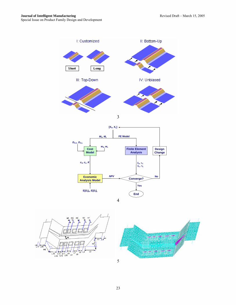
The second step is to generate flexible design alternatives for embedding dimensional flexibility into the floor pan. After considering platform constraints and other design criteria, four design alternatives are generated and shown in Fig. 3.
(Insert Fig. 3) The first alternative is a customized design, where two separate floor pans are designed for short and long
variants. Floor pans are fabricated using separate stamping dies and tools, requiring separate investments for floor pans of different length. This is the baseline design, with no geometric flexibility embedded into the floor pan itself.
For the second design, called “bottom-up” design, the main floor pan is designed to fit the short floor pan length specification. To satisfy the long floor pan length requirement, an extension piece is spot welded to the main floor pan. This design allows the addition of floor pans with different lengths through the addition of the extension piece with dimensional restriction Lmin ≤ L, where Lmin is the minimum floor pan length achievable by this design, bounded by the length of the short floor pan. Separate stamping dies are required for the short floor pan and the extension piece. Moreover, additional investments are required for spot welding facilities due to the extra welding process for the long floor pan.
The third design, called “top-down” design, incorporates flexibility into the floor pan in a different way. The main floor pan is designed to meet the long floor pan length requirement. To manufacture the short floor pan, the end of the original floor pan is simply trimmed to meet the geometric specification. This design requires stamping and blanking dies for fabrication of the long floor pan, plus additional initial investments for short floor pan fabrication (trimming die). Because of the additional tooling investments (non-recurring cost), extra labor for fabrication and extra time required (recurring production cost), the unit cost of the short floor pan is higher than the long floor pan. The floor pan has the dimensional restriction L ≤ Lmax, where Lmax is the maximum floor pan length achievable by this design, bounded by the length of the original floor pan.
The last design is the most flexible design, where two equal-length pieces are welded together to achieve any floor pan length requirement with lower and upper bound Lmin ≤ L ≤ Lmax. This design requires stamping and blanking dies for fabrication of two equal length pieces, plus additional investments for welding facilities. The cost of floor pan fabrication and assembly is the same for both the long and short floor pans, unbiased toward any
6

Journal of Intelligent Manufacturing Revised Draft – March 15, 2005 Special Issue on Product Family Design and Development
floor pan size in terms of the unit cost, since the same sub-components and manufacturing processes are used. This is the design with the highest degree of flexibility, where sub-components can be adjusted (by sliding) to any floor pan length within the pre-established lower and upper bound. Key dimensions for short and long floor pans are shown in Table 1.
(Insert Table 1)
Design II and Design IV require additional spot welding for sub-component assembly. Extra spot welding is
required in addition to spot welding required for a standard floor pan assembly. It is determined that the long floor pan for Design II and all floor pans for Design IV require 35 additional spot welding connections each, assuming 50 mm clearance between each weld connection. Given the overall floor pan dimensions, floor pan geometry will be optimized for minimum overall mass.
Four different design alternatives were presented, each with its own advantages and disadvantages. In the subsequent section, an optimization process for each design alternative is presented in order to quantify the benefits and costs of each alternative. 3.4 Design Alternative Optimization (Step III) 3.4.1 Optimization Framework
Fig. 4 shows the flow diagram of the multidisciplinary optimization for each floor pan alternative. Given geometric design vectors for short and long floor pans (xS, xL), finite element models of short and long floor pans are generated and analyzed for bending and torsion requirements (δS, τS, δL, τL). Concurrently, masses of the floor pans (MS, ML), calculated from floor pan design vectors, are passed onto the cost model, yielding the total investment cost (K) and the unit cost for short and long floor pans (cS, cL), given the initial annual demand for each floor pan (Do,S, Do,L) and the total number of welding connections (wS, wL). Cost data is then passed onto the economic analysis model, where the total expected cost expenditure is calculated in terms of Net Present Value (NVP), given the expected future demand for short and long floor pans (E[Dt]S, E[Dt]L), based on historical data. The mathematical statement in Eq. (5) is implicitly embedded in this optimization framework, since minimizing the mass of the floor pan will minimize the investment and production costs of floor pans, which in turn, will minimize total cost expenditure over the specified time horizon. The finite element analysis model, cost model, and economic analysis model are explained in subsequent sections.
(Insert Fig. 4)
3.4.2 Finite Element Model
In this case study, a simplified finite element model of the underbody is modeled by linear structural shell elements and a Finite Element Analysis is conducted. The commercial FEA software package Ansys® is used. Both ends near the front and rear axles are fixed. The geometry of the floor pan is controlled by design vectors xS (for the short floor pan) and xL (for the long floor pan). Each design vector has 31 design variables – 17 length variables, 8 height variables, 5 width variables, and a thickness variable. Fig. 5 shows the finite element analysis model with design variables. All design variables affect the structural performance, but only the thickness is used for subsequent cost analysis.
The displacements obtained in the bending and torsion analyses are used to compute the bending and torsion stiffness. In an overall design involving the entire underbody platform, the interactions with other components must be considered because the floor pan affects the entire vehicle stiffness and bending performance.
(Insert Fig. 5)
7

Journal of Intelligent Manufacturing Revised Draft – March 15, 2005 Special Issue on Product Family Design and Development
3.4.3 Cost Model
A proprietary cost model was utilized to construct the costing relationships this case study. The following assumptions are made for all proposed designs.
• The investment costs consist of line equipments and tooling investments for the blanking, stamping and
welding processes. Transfer press technology is assumed for the fabrication of the floor pan, with long and short floor pan sharing the same press line for fabrication and welding processes.
• Welding lines for all designs are assumed to be flexible, i.e. they can accommodate any floor pan lengths within the pre-established boundary. Flexible welding tool investment costs are assumed to be twice the costs of inflexible welding tools.
• Blanking die investment is 10% of a new stamping die investment. • Only two different floor pan lengths (long and short) are produced at any given time. • Production volume of the floor pan is equal to the demand for the floor pan. A response surface of the cost model is created to calculate the unit cost of the floor pan as a function of floor pan mass and the annual demand. Once cS, cL, and K are determined, they are passed onto the economic analysis model. 3.4.4 Economic Analysis Model
Given the total investment cost and the unit the cost of short and long floor pans, the model calculates the total expected cost expenditure for each design alternative in terms of current Net Present Value. The following assumptions are made for the economic analysis model:
• The total life cycle of the vehicle platform is set to 15 years (T = 15). This assumes that there will be three
generations of vehicle models with five years of production life cycle each. • Blanking dies, stamping dies and welding tools are refurbished every five years when vehicle models are
remodeled. Costs for refurbishing are assumed to be 25% of a new die and tool cost, assuming no engineering design changes. In this case study, it is assumed that unless there is a change in floor pan lengths, there will be no new investment costs for floor pans other than refurbishing costs.
• Investment for new tooling or refurbishing occurs a year before the start of the new model production. For this case study, the investment occurs during year 0, 5 and 10.
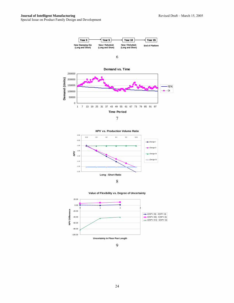
Fig. 6 shows the fixed investment schedule for the floor pan production.
(Insert Fig. 6) Net Present Value (NPV) is the total present value of future cash flows over a fixed time period, including the
initial investment. In this case study, the total expected cost expenditure, expressed in terms of NPV, is used as a measure of the economic performance of each design alternative, given uncertainties in future demand. NPV can be obtained by Eq. (8).
0 (1 )
Tt
tt
CFNPV
r=
=+∑ (8)
8

Journal of Intelligent Manufacturing Revised Draft – March 15, 2005 Special Issue on Product Family Design and Development
where T is the number of time periods and CFt is the total cash flow at time period t. The discount rate r captures the time value of money, comprised of the risk free interest rate plus a risk premium. Discount rates typically used in industry are approximately 15 ~ 20 % per year (de Neufville, 1990). In this case study, an annual discount rate of 6 % (risk free interest rate) is used, since the risk premium is captured by Monte Carlo simulation during the uncertainty analysis. Period cash flow is the total cash flow during time period j. The equation for calculating the cash flow at time period t is (9) ; 1...v v v
t t tCF C K v Y= − − = where Ct
v is the total variable cost from the component production and Ktv is the total capital investment at time
period t when the flexible design alternative v is implemented. The negative sign indicates that Ctv and Kt
v are cash outflow. The total variable cost Ct
v for the time period t is
,1
Eq
v vt i t
i
C c D=
i⎡ ⎤⎡ ⎤= ⎣ ⎦⎣ ⎦∑ (10)
where ci
v is the unit cost of ith component variant and when the flexible design alternative v is implemented at time t. E[Dt,i] is the expected demand of ith component variant at time t (see Eq. (13)). The component variant unit cost ci
v is ic c (11) ,
v v vi f i a,c= +
,
where cf,i
v is the fabrication cost of the ith component variant and ca,iv is the assembly cost of the ith variant when
the flexible design alternative v is implemented. The fabrication costs are calculated by the cost model and passed onto the economic analysis model. The assembly cost is pre-determined from the proprietary assembly cost model as a function of the number of welding connections and the total planned annual production volume. Finally, Kt
v, the total capital investment cost at time period t, is
,L t T
v v vt t
K k k= + (12) where kL,t
v is the total line investment cost and kT,tv is the total tooling investment cost at time period t, when
design alternative v is implemented. In this economic analysis model, future demands for short and long floor pan are estimated based on historical
sales data (1997 ~ 2003) of the vehicles that are planned to be built on this particular vehicle platform. The assumption is that the past historical trend will continue in the future. Expected demand for a particular component at time t is ( )E[ ] ; 1..t
t o FD D e t Tα= = (13) where Do is the initial annual demand, α is the drift coefficient indicating the trend of demand, and TF is the number of time period into the future. The drift coefficient (α) and the volatility coefficient (σ) are for a particular vehicle sold, and can be calculated from Eq. (14) and Eq. (15), assuming sufficient historical data is available. The volatility coefficient is an important parameter required for future uncertainty analysis later on.
9

Journal of Intelligent Manufacturing Revised Draft – March 15, 2005 Special Issue on Product Family Design and Development
, ,
2 1
(ln ln )1( )2
HT
h t h tt
H
D D
Tα σ
−=
−− =
∑ 1
(14)
( ), , 1 1stdev ln ln( ) Ht T
h t h t tD Dσ
=
− =⎡ ⎤= −⎣ ⎦ (15)
TH is the total number of historical time periods observed and Dh,t is the historical vehicle demand at time t. Once
floor pans for each design alternative are optimized, the optimum designs are evaluated under future uncertainty. Table 2 lists required parameters for the economic analysis model and uncertainty analysis later on. The initial
annual vehicle demand (Do), trend coefficient (α) and volatility coefficient (σ) are obtained from historical data (1997 ~ 2003) of real vehicles that are planned to be developed on this particular vehicle platform.
(Insert Table 2)
3.4.5 Optimization Results
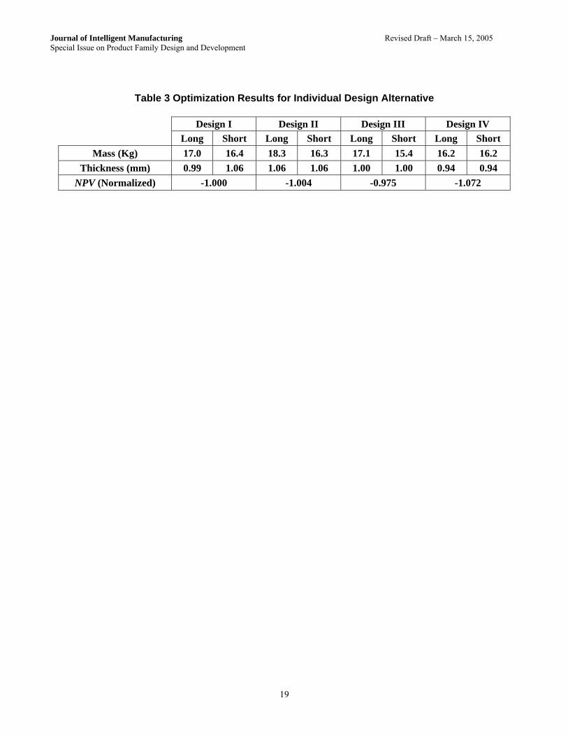
Using the optimization framework described in the previous section, the optimal xS and xL are obtained, yielding results shown in Table 3. Optimized floor pan masses, thicknesses and NPV for each design alternative are listed. In the optimization, the floor pan thickness was treated as a continuous design variable. NPV values for design alternatives are normalized by the NPV value of Design I. Design II, III and IV have uniform thicknesses for long and short floor pans since they are using the same floor pan for both lengths. Also, masses for the long floor pan in Design II and both floor pans in Design IV account for the 15 mm overlap required for spot welding. Long and short floor pans for Design I have different thicknesses, since the floor pans are customized for different lengths. NPV for each design alternative is normalized to the NPV value of Design I. The negative sign in front of NPV values indicates that they are cash outflows, since revenue is only generated for the entire vehicle, not for individual components of the product or platform. From the optimization, with deterministic demand, Design III resulted in the smallest cost expenditure. While the cost differences between alternatives appear small one must keep in mind that profit margins are very tight in the automotive industry. We will see that these small differences are amplified, once uncertainty and flexibility are considered.
(Insert Table 3) 3.5 Uncertainty Analysis (Step IV) 3.5.1 Overview
Uncertainty analysis of floor pan design alternatives during the lifetime of a vehicle platform is critical for estimating the overall economic performance of each flexible design alternative. In this case study, the identified uncertainties are future demand for each floor pan, and the potential engineering change (floor pan length) during major remodeling of the vehicle family every five years. For the future floor pan demand, even though expected production demand is known, the actual demand from customers is highly uncertain. It is assumed that the floor pan length change occurs within pre-defined dimensional limits Lmin ≤ L ≤ Lmax.
It is further assumed that the initially chosen design alternative will be implemented throughout the life of the platform. Geometric Brownian Motion (GBM) is used to model uncertain future demand for short and long floor pans, assuming the historical trend continues in the future within a pre-established yearly volatility.
Annual demand for different floor pans varies from year to year with increasing uncertainty as the future forecast horizon increases. Floor pan demand at time t+1 can be estimated by
2
[( ) ]2
1
t t
t tD D eσα σε− ∆ + ∆
+ = (16)
10

Journal of Intelligent Manufacturing Revised Draft – March 15, 2005 Special Issue on Product Family Design and Development
Where Dt is the demand at time t, α is the drift coefficient, σ is the volatility coefficient (Eq. (15)), Δt is the unit change in time (a year for this case study), and ε is a normally distributed random number with N(0,1). Substituting Eq. (16) into Eq. (10) and calculating the actual NPV for time period t in Eq. (8), the actual expected NPV for the design alternatives can be calculated. Fig. 7 shows an example plot of the expected demand and one possible outcome of the actual demand over the specified time period.
(Insert Fig. 7)
Simulating the actual demand scenarios many times through the Monte Carlo simulation, E [NPV] can be calculated as
[ ] 1
SN
kk
S
NPVE NPV
N==∑
(17)
3.5.2 Deterministic Analysis
Before the actual uncertainty analysis, a deterministic analysis based on the fixed floor pan production volume is performed. Fig. 8 shows deterministic cost expenditure from the floor pan production over the lifetime of the vehicle platform (expressed in terms of NPV) as a function of floor pan production volume ratio (long:short). The assumption is that the annual production volume ratio remains constant (based on the total long and short floor pan production volume of 465,000 units) throughout the life of the vehicle platform. The graph is shown in Fig. 9. Since the overall cost expenditure is negative, the design closest to the abscissa is the best design with minimum cost expenditure. The NPV values are normalized with respect to the NPV value of Design I when the production volume ratio is 0:10.
(Insert Fig. 8)
Design III has the best economic performance over most ranges. Additionally, Design III has very little
sensitivity to the change in the production volume ratio. This is due to the fact that the unit cost difference between the long and short floor pan is very small, making it insensitive to the production volume ratio change. The slope of Design III is positive, while the other lines have negative slopes. This is due to the fact that for Design III, the short floor pan is more expensive than the long floor pan, i.e. the more long floor pans are produced, the smaller the total costs. Design IV, the design with the highest degree of flexibility, does not perform well compared to the other design alternatives. However, this design is also not sensitive to the production volume ratio, since the unit costs for short and long floor pans are the same. Finally, if there is a case where the initial production volume ratio is positioned near the crossover points between each design NPV line, the future trend of the production volume ratio becomes an important criterion for the selection of the best design alternative.
The results indicate that under deterministic conditions, with current demand trends, it would be best to choose Design III, since it has the smallest net cost expenditure. However, since the actual future demands for both long and short floor pans are uncertain, we need to capture all possible instances of future demand scenarios to make the best design selection. In the next section, results of the uncertainty analysis are presented. 4. Results 4.1 Scenario Evaluation
11

Journal of Intelligent Manufacturing Revised Draft – March 15, 2005 Special Issue on Product Family Design and Development
Four different scenarios are evaluated, in ascending order of increasing uncertainty. They are summarized in Table 4.
(Insert Table 4)
Initially, it is assumed that there is no uncertainty in floor pan lengths (Scenario I), i.e. there is only demand
uncertainty. Next, the length of one floor pan is treated as uncertainty (Scenario II and III), its length requirement changing at year 5 and year 10. Finally, lengths of both floor pans are treated as uncertain (Scenario IV). Subsequent sections outline how uncertainty affects each design alternative, and the results are presented in section 4.2. 4.1.1 No Floor Pan Lengths Change (Scenario I)
Since there is no uncertainty in floor pan lengths in this scenario, the only investment costs incurred in year 5 and 10 are refurbishing costs of fabrication dies. Monte Carlo simulation is performed to estimate the expected lifetime cost expenditure for each design alternative. Each simulation comprises 25,000 runs. 4.1.2 Uncertain Short Floor Pan Length (Scenario II)
This time, the short floor pan length is treated as uncertainty. The short floor pan length changes occur in year 5 and 10, when the vehicle family goes through major redesign. Each design alternative will incur different investment costs. • Design I: A new stamping die and blanking die for the short floor pan are required. Long floor pan dies are
refurbished. • Design II: New investments for both short floor pan and the extension piece are required. For this design,
flexibility does not have any benefit over the inflexible design. • Design III: The blanking die that trims the long floor pan into the short floor pan must be redesigned. • Design IV: No new investments, other than refurbishing costs, are required. Flexibility is already built in. Again, Monte Carlo simulation is performed for each design alternative. 4.1.3 Uncertain Long Floor Pan Length (Scenario III)
This time, the long floor pan length is treated as uncertain. The long floor pan length changes occur in year 5 and 10, when the vehicle models are redesigned. Each design alternative will incur different investment costs. • Design I: A new long floor pan stamping die and a blanking die is required. Short floor pan dies are
refurbished. • Design II: A new extension piece is required to accommodate the new length. Blanking and stamping dies for
a new extension piece are required. Short floor pan dies are refurbished. • Design III: A new stamping die and blanking die for the long floor pan are required. The blanking die for the
short floor pan is refurbished. • Design IV: No new investments, other than refurbishing costs, are required. Flexibility is already built in. 4.1.4 Uncertain Floor Pan Lengths (Scenario IV)
Finally, both long and short floor pan lengths are treated as uncertainties. The floor pan length changes occur inn year 5 and 10 when the entire vehicle family goes through a major change up. Each design alternative will incur different investment costs. • Design I: New stamping and blanking dies for both long and short floor pan are required. • Design II: Investment costs for the short floor pan and extension piece are required. • Design III: New investment costs for the large floor pan (blanking and stamping dies) and blanking die (for
short floor pan trimming) are required.
12

Journal of Intelligent Manufacturing Revised Draft – March 15, 2005 Special Issue on Product Family Design and Development
• Design IV: No new investments, other than refurbishing costs, are required. Flexibility is already built in. 4.2 Simulation Results
The following table lists E [NPV] of each design alternative for all evaluated scenarios. Values are normalized with respect to the E [NPV] value of Design I for scenario I.
(Insert Table 5)
From the simulation, it appears that Design III has the best economic performance among all designs in all scenarios. Design II, another flexible design, had worse economic performance than the inflexible Design I in scenarios I and II. This can be attributed to the fact that the production volume trend (shown in Fig. 8) shifted to the region where Design I becomes more favorable. Another influencing factor is the way the flexibility is built into the floor pan for Design II. When the short floor pan length became uncertain, Design II needed new investments on all sub-components, resulting in higher cost expenditures than Design I. Another interesting result is that Design IV, the most flexible design, had the worst economic performance overall, regardless of degrees of uncertainty. This raises a possible future research question, “how much flexibility is optimal when the degree of uncertainty is known?”
The final analysis consists of comparing the difference between the economic performance of flexible designs to that of the inflexible design as the degree of uncertainty increases. Fig. 9 shows the ΔE[NPV] between flexible designs (Design II, III, and IV) and the inflexible design (Design I) as the degree of uncertainty in floor pan length increases.
(Insert Fig. 9)
The abscissa represents the degree of uncertainty in the floor pan lengths. The floor pan lengths can be certain for both long and short floor pans (degree = 0), uncertain for one of the floor pans (degree = 1), or uncertain for both floor pans (degree = 2). The ordinate represents the difference between the average cost expenditure of flexible designs (Design II, III, and IV) and the inflexible design (Design I). As observed in Fig. 9, it is clear that flexibility has more value as the degree of uncertainty increases. 4.3 Discussion
The analysis results reveal important issues that must be considered when designing flexible platform components. They are: the way flexibility is incorporated into the component, the degree of flexibility, and the production volume ratio trend between variants in the product family.
First, the way flexibility is embedded into a component has very significant economic consequences over the lifetime of the platform component. In this case study, Design III was almost always the best design in terms of economic benefit, while the flexible Design II performed worse than the customized Design I under certain circumstances. Also, Design III and IV were economically robust to uncertain production volume ratios due to small differences in long and short floor pan manufacturing costs. Design III is the component, which is optimized for the larger variant, with material being removed to create the shorter variant (“top-down”).
Second, consideration must be given to the degree of future uncertainty. As demonstrated in the previous section, the value of flexible design increased as the degree of uncertainty increased. However, Design IV, the design with “continuous” flexibility, was too expensive and it failed to give the best return even when the degree of uncertainty increased. In all scenarios, flexible designs with “discrete” levels of flexibility performed much better.
Finally, the future trend of the production volume ratio between variants in the same product family can be an important factor. When the initial production volume ratio is near the crossover point, the future production volume ratio trend must be observed carefully in order to select the best design.
13

Journal of Intelligent Manufacturing Revised Draft – March 15, 2005 Special Issue on Product Family Design and Development
The proposed design process provides a stepping-stone for future research, namely the design process for flexible complex systems (e.g. product platforms). Complex systems can respond to future uncertainties more easily by properly identifying and embedding flexibility into a key subset of complex system elements. However, one must take into account the interaction between related elements within the system, which were not present in the case of a single component discussed in this paper. Further research on system change propagation and system decomposition strategy, in addition to work presented in this paper, is needed to address this problem.
5. Summary
In this paper, a design process for flexible product platform components is introduced. Embedding flexibility allows manufacturers to respond to changing market needs with a minimum increase in investment costs and complexity. Once important product platform criteria and future uncertainties are identified, several flexible design alternatives are generated. Each design alternative is optimized for minimum cost expenditure while satisfying performance constraints. Uncertainty analysis is performed to determine the best design alternative. The design process is demonstrated through a detailed case study, where flexible design alternatives for a vehicle floor pan are generated and evaluated for lifetime cost expenditure under uncertain demand and uncertain geometric specifications.
Results revealed that how flexibility is built into the component has significant economic consequences over the lifetime of the platform component. Additionally, it is demonstrated that as the degree of future uncertainty increases, the value of component-embedded flexibility increases. Analysis also demonstrated that too much flexibility may not result in the best economic performance, which gives rise to the question “what is the optimal degree of flexibility?” Production volume trends for component variants are very important factors to consider when there are several competing flexible designs. Finally, application of the proposed design process to a complex system is discussed as a promising future research topic. Acknowledgements
The work presented in this paper was supported by General Motors. Such support does not constitute an endorsement by the company of the conclusions expressed by the authors in the paper.
14

Journal of Intelligent Manufacturing Revised Draft – March 15, 2005 Special Issue on Product Family Design and Development
References Black, F. and Scholes, M. (1973) The pricing of option and corporate liabilities. Journal of Political Economy, 81, 637-654. Bremmer, R. (1999) Cutting Edge Platforms. Financial Times Automotive World, September, 30-38. Cook, H. E. (1997) Product Management: Value, Quality, Cost, Price, Profit and Organization, Chapman & Hall, New York, NY. de Neufville, R. (1990) Applied Systems Analysis: Engineering Planning and Technology Management, McGraw-Hill, New York, NY. de Weck, O., Suh, E. S. and Chang, D. (2003) Product family and platform portfolio optimization. Proceedings of the 2003 Design Engineering Technical Conference, September 2-6, 2003, Chicago, Illinois, USA, DETC2003/DAC-48721. ESD Symposium Committee. (2002) Engineering systems research and practice. ESD Internal Symposium, May 29-31, 2002, Massachusetts Institute of Technology, Cambridge, MA. Fellini, R., Kokkolaras, M., Michelena, N., Papalambros, P., Saitou, K., Perez-Duarte, A. and Fenyes, P. A. (2002) A sensitivity-based commonality strategy for family products of mild variation, with application to automotive body structures. Proceedings of the 9th AIAA/ISSMO Symposium on Multidisciplinary Analysis and Optimization, September 4-6, 2002, Atalanta, Georgia, USA, AIAA-2002-5610. Georgiopoulos, P., Fellini, R., Sasena, M. and Papalambros, P. Y. (2002) Optimal design decisions in product portfolio valuation. Proceedings of 2002 Design Engineering Technical Conference, September 29 – October 2, 2002, Montreal, Canada, DETC2002/DAC-34097. Kidd, S. L. (1998) A systematic method for valuing a product platform strategy. LFM Master Thesis, Massachusetts Institute of Technology, Cambridge, MA. Li, H. and Azarm, S. (2000) Product design selection under uncertainty and with competitive advantage. Journal of Mechanical Design, 122(4), 411-418. Li, H. and Azarm, S. (2002) An approach for product line design selection under uncertainty and competition. Journal of Mechanical Design, 124(3), 385-392. Meyer, M. H. and Lehnerd, A. P. (1997) The Power of Product Platforms: Building Value and Cost Leadership, The Free Press, New York, NY. Nelson, S. A., II, Parkinson, M. B. and Papalambros, P. Y. (2001) Multicriteria optimization in product platform design. Journal of Mechanical Design, 123(2), 199-204. Martin, M. V. and Ishii, K. (2002) Design for variety: Developing standardized and modularized product platform architectures. Research in Engineering Design, 13(4), 213-235.
15

Journal of Intelligent Manufacturing Revised Draft – March 15, 2005 Special Issue on Product Family Design and Development
Pine, B. J. (1993) Mass Customization: The New Frontier in Business Competition, Harvard Business School Press, Boston, MA. Robertson, D. and Ulrich, K. (1998) Planning product platforms. Sloan Management Review, 39(4), 19-31. Sanderson, S. W. and Uzumeri, M. (1997) Managing Product Families, Irwin Professional Publication, Chicago, IL. Sethi, A. K. and Sethi, S. P. (1990) Flexibility in manufacturing: A survey. The International Journal of Flexible Manufacturing Systems, 2, 289-328. Simpson, T. W., Maier, J. R. A. and Mistree, F. (2001) Product platform design: Method and application. Research in Engineering Design, 13(1), 2-22. Trigeorgis, L. (1996) Real Options: Managerial Flexibility and Strategy in Resource Allocation, The MIT Press, Cambridge, MA.
16

Journal of Intelligent Manufacturing Revised Draft – March 15, 2005 Special Issue on Product Family Design and Development
Table 1 Floor Pan Geometric Specifications
Key Dimensions Short Floor Pan Long Floor Pan Length (mm) 1180 1305 Width (mm) 1445 1445
Thickness (mm) To Be Determined by Optimization
17

Journal of Intelligent Manufacturing Revised Draft – March 15, 2005 Special Issue on Product Family Design and Development
Table 2 Economic Analysis Parameters Floor Pan Size Parameters Short Long
Do 60,000 405,000α -5.52 % 2.09 %σ 13.27 % 7.35 %
18
Journal of Intelligent Manufacturing Revised Draft – March 15, 2005 Special Issue on Product Family Design and Development
Table 3 Optimization Results for Individual Design Alternative
Design I Design II Design III Design IV Long Short Long Short Long Short Long Short
Mass (Kg) 17.0 16.4 18.3 16.3 17.1 15.4 16.2 16.2 Thickness (mm) 0.99 1.06 1.06 1.06 1.00 1.00 0.94 0.94
NPV (Normalized) -1.000 -1.004 -0.975 -1.072
19

Journal of Intelligent Manufacturing Revised Draft – March 15, 2005 Special Issue on Product Family Design and Development
Table 4 Evaluated Scenarios
Scenarios Short Floor Pan Length (Year 5, 10)
Long Floor Pan Length (Year 5, 10)
Scenario I Fixed Fixed Scenario II Uncertain Fixed Scenario III Fixed Uncertain Scenario IV Uncertain Uncertain
20

Journal of Intelligent Manufacturing Revised Draft – March 15, 2005 Special Issue on Product Family Design and Development
Table 5 E[NPV] of Design Alternatives for Simulated Scenarios
E[NPV] (Normalized) Scenarios I II III IV Scenario I -1.000 -0.998 -0.987 -1.164Scenario II -1.076 -1.081 -1.055 -1.163Scenario III -1.075 -1.072 -1.061 -1.162Scenario IV -1.082 -1.079 -1.061 -1.161
21

Journal of Intelligent Manufacturing Revised Draft – March 15, 2005 Special Issue on Product Family Design and Development
1
2
22
Journal of Intelligent Manufacturing Revised Draft – March 15, 2005 Special Issue on Product Family Design and Development
3
Finite ElementAnalysis
Cost Model
Economic Analysis Model
[XS, XL]
cS, cL, K
E[Dt]S, E[Dt]L
Converge?NPV
DO,S , DO,L
End
δS, τS
δL, τL
MS, ML FE Model
Yes
No
wS, wLDesign Change
4
5
23
Journal of Intelligent Manufacturing Revised Draft – March 15, 2005 Special Issue on Product Family Design and Development
Year 0 Year 5 Year 10 Year 15
End of PlatformNew Stamping Die (Long and Short)
New / Refurbish (Long and Short)
New / Refurbish (Long and Short)
Year 0 Year 5 Year 10 Year 15
End of PlatformNew Stamping Die (Long and Short)
New / Refurbish (Long and Short)
New / Refurbish (Long and Short)
6
Demand vs. Time
0
50000
100000
150000
200000
250000
1 7 13 19 25 31 37 43 49 55 61 67 73 79 85 91 97
Time Period
Dem
and
(Uni
ts)
E[Dt]
Dt
7
NPV vs. Production Volume Ratio
-1.25
-1.20
-1.15
-1.10
-1.05
-1.00
-0.95
-0.900:10 2:8 4:6 6:4 8:2 10:0
Long : Short Ratio
NPV
Design I
Design II
Design III
Design IV
8
Value of Flexibility vs. Degree of Uncertainty
-100.00
-80.00
-60.00
-40.00
-20.00
0.00
20.00
0 1 2 3
Uncertainty in Floor Pan Length
NP
V D
iffer
ence
E[NPV (II)] - E[NPV (I)]E[NPV (III)] - E[NPV (I)]E[NPV (IV)] - E[NPV (I)]
9
24

Journal of Intelligent Manufacturing Revised Draft – March 15, 2005 Special Issue on Product Family Design and Development
Caption to Illustrations Fig. 1 Proposed Design Process Fig. 2 Vehicle Underbody Structure Fig. 3 Proposed Flexible Floor Pan Designs Fig. 4 Design Alternative Optimization Flow Diagram Fig. 5 (Left) Design Features of Floor Pan, (Right) Floor Pan Finite Element Model Fig. 6 Timeline for Floor Pan Related Investment Fig. 7 Example of Future Demand Model Using GBM Fig. 8 NPV of Each Design Alternative vs. Production Volume Ratio Fig. 9 Value of Flexibility
25