flexible wing designs with sensor control …...1 fundamental aeronautics program subsonic fixed...
TRANSCRIPT
1
Fundamental Aeronautics Program
Subsonic Fixed Wing Project
National Aeronautics and Space Administration
www.nasa.gov
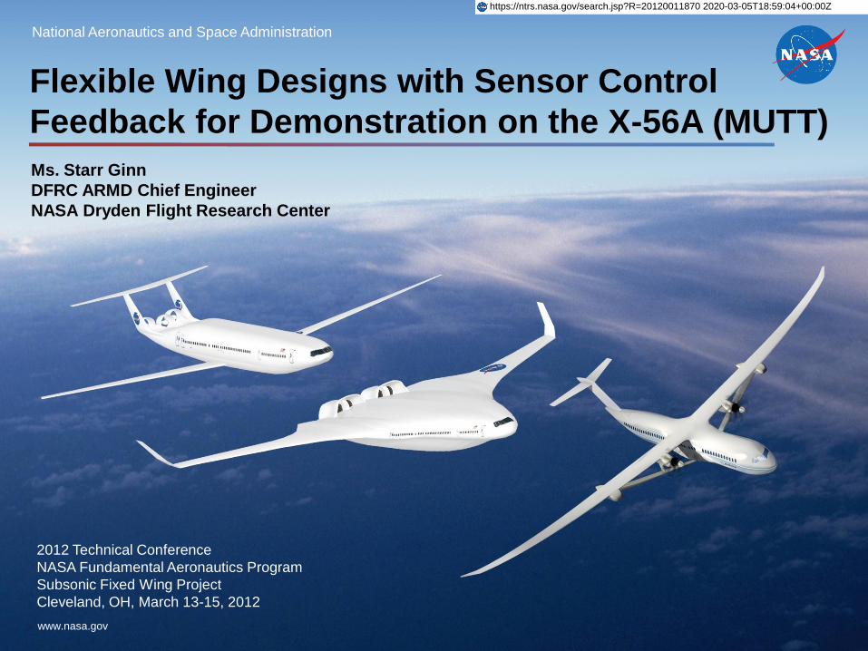
Flexible Wing Designs with Sensor Control
Feedback for Demonstration on the X-56A (MUTT)
Ms. Starr Ginn
DFRC ARMD Chief Engineer
NASA Dryden Flight Research Center
2012 Technical Conference
NASA Fundamental Aeronautics Program
Subsonic Fixed Wing Project
Cleveland, OH, March 13-15, 2012
https://ntrs.nasa.gov/search.jsp?R=20120011870 2020-03-05T18:59:04+00:00Z

2
Fundamental Aeronautics Program
Subsonic Fixed Wing Project
Outline
• SFW Strategic Thrusts & Technical Challenges
• High Aspect Ratio Elastic Wing
– Flight Dynamics & Control (Chris Reagan)
– ASE Controller Design using Distributed Sensing (Marty Brenner)
– Fiber Optic Strain Sensing (FOSS) (Allen Parker)
– Fiber Optic Wing Shape Sensing (FOWSS) (John Bakalyar/Lance Richards)
– Aeroservoelastic Tailored Wings using MDAO (Chan-Gi Pak)
– Passive Aeroelastic Design of High AR Elastic wing (Jim Moore)
– Distributed Control Effectors (Dan Moerder)
• Focused System’s Research Objectives
– Access to Models and Flight Data
– High Aspect Ratio Elastic Wing Technology Roadmap
• X-56a Multi-Utility Technology Testbed (MUTT) – John Bosworth(DFRC Chief Engineer) and Gary Martin (DFRC Project Manager)
3
Fundamental Aeronautics Program
Subsonic Fixed Wing Project
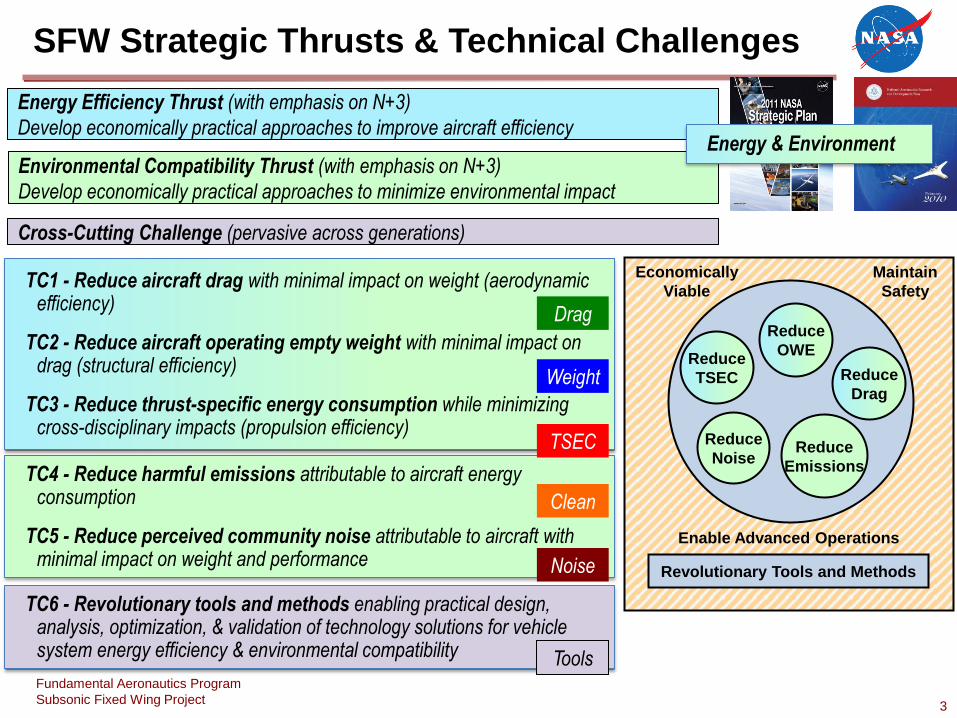
SFW Strategic Thrusts & Technical Challenges
Reduce
TSEC
Reduce
OWE
Reduce
Drag
Reduce
Noise Reduce
Emissions
Economically
Viable
Revolutionary Tools and Methods
Maintain
Safety
Enable Advanced Operations
Energy Efficiency Thrust (with emphasis on N+3)
Develop economically practical approaches to improve aircraft efficiency
Environmental Compatibility Thrust (with emphasis on N+3)
Develop economically practical approaches to minimize environmental impact
Cross-Cutting Challenge (pervasive across generations)
Energy & Environment
TC6 - Revolutionary tools and methods enabling practical design, analysis, optimization, & validation of technology solutions for vehicle system energy efficiency & environmental compatibility
TC4 - Reduce harmful emissions attributable to aircraft energy consumption
TC5 - Reduce perceived community noise attributable to aircraft with minimal impact on weight and performance
TC1 - Reduce aircraft drag with minimal impact on weight (aerodynamic efficiency)
TC2 - Reduce aircraft operating empty weight with minimal impact on drag (structural efficiency)
TC3 - Reduce thrust-specific energy consumption while minimizing cross-disciplinary impacts (propulsion efficiency)
TSEC
Clean
Weight
Drag
Noise
Tools
4
Fundamental Aeronautics Program
Subsonic Fixed Wing Project
active controls
load alleviation
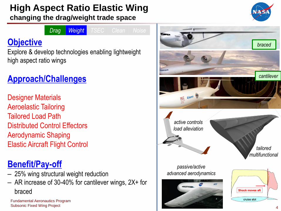
High Aspect Ratio Elastic Wing changing the drag/weight trade space
Objective Explore & develop technologies enabling lightweight
high aspect ratio wings
Approach/Challenges
Designer Materials
Aeroelastic Tailoring
Tailored Load Path
Distributed Control Effectors
Aerodynamic Shaping
Elastic Aircraft Flight Control
Benefit/Pay-off – 25% wing structural weight reduction
– AR increase of 30-40% for cantilever wings, 2X+ for
braced
TSEC Clean Weight Drag Noise
braced
cantilever
tailored
multifunctional
passive/active
advanced aerodynamics
5
Fundamental Aeronautics Program
Subsonic Fixed Wing Project
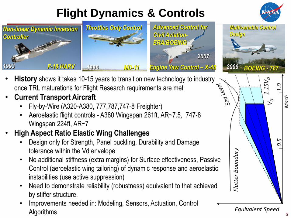
Flight Dynamics & Controls
F-18 HARV
Non-linear Dynamic Inversion
Controller
Engine Yaw Control – X-48
Advanced Control for
Civil Aviation-
ERA/BOEING
Multivariable Control
Design
BOEING - 787 MD-11
Throttles Only Control
1996 1993
2007
2009
• History shows it takes 10-15 years to transition new technology to industry
once TRL maturations for Flight Research requirements are met
• Current Transport Aircraft • Fly-by-Wire (A320-A380, 777,787,747-8 Freighter)
• Aeroelastic flight controls - A380 Wingspan 261ft, AR~7.5, 747-8
Wingspan 224ft, AR~7
• High Aspect Ratio Elastic Wing Challenges • Design only for Strength, Panel buckling, Durability and Damage
tolerance within the Vd envelope
• No additional stiffness (extra margins) for Surface effectiveness, Passive
Control (aeroelastic wing tailoring) of dynamic response and aeroelastic
instabilities (use active suppression)
• Need to demonstrate reliability (robustness) equivalent to that achieved
by stiffer structure.
• Improvements needed in: Modeling, Sensors, Actuation, Control
Algorithms
Flu
tter
Bo
un
da
ry
VD
1
.15
VD
1.0
0
.5
Ma
ch
Equivalent Speed
6
Fundamental Aeronautics Program
Subsonic Fixed Wing Project
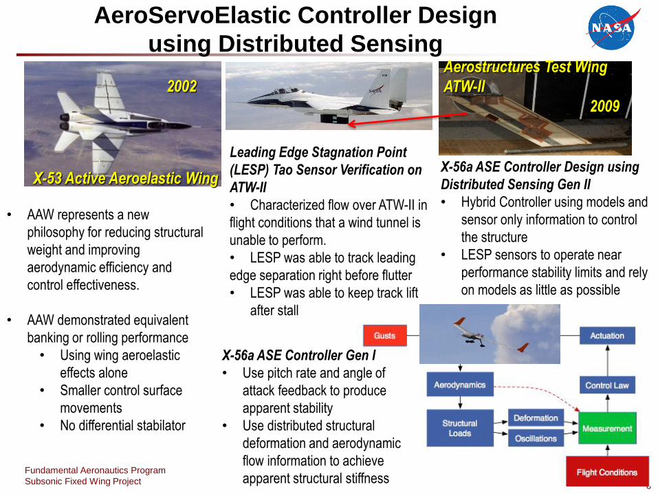
AeroServoElastic Controller Design
using Distributed Sensing Aerostructures Test Wing
ATW-II
X-53 Active Aeroelastic Wing
• AAW represents a new
philosophy for reducing structural
weight and improving
aerodynamic efficiency and
control effectiveness.
• AAW demonstrated equivalent
banking or rolling performance
• Using wing aeroelastic
effects alone
• Smaller control surface
movements
• No differential stabilator
Leading Edge Stagnation Point
(LESP) Tao Sensor Verification on
ATW-II
• Characterized flow over ATW-II in
flight conditions that a wind tunnel is
unable to perform.
• LESP was able to track leading
edge separation right before flutter
• LESP was able to keep track lift
after stall
2009
X-56a ASE Controller Design using
Distributed Sensing Gen II
• Hybrid Controller using models and
sensor only information to control
the structure
• LESP sensors to operate near
performance stability limits and rely
on models as little as possible
2002
X-56a ASE Controller Gen I
• Use pitch rate and angle of
attack feedback to produce
apparent stability
• Use distributed structural
deformation and aerodynamic
flow information to achieve
apparent structural stiffness
7
Fundamental Aeronautics Program
Subsonic Fixed Wing Project
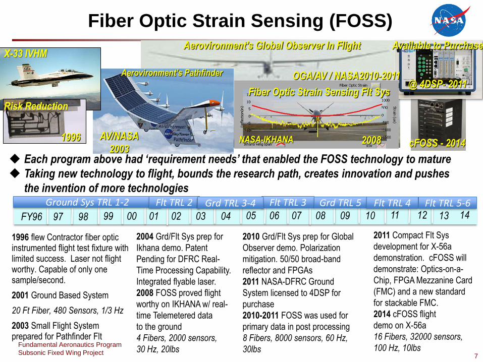
Fiber Optic Strain Sensing (FOSS) Aerovironment’s Global Observer In Flight Available to Purchase
@ 4DSP- 2011
1996 flew Contractor fiber optic instrumented flight test fixture with limited success. Laser not flight worthy. Capable of only one sample/second.
2001 Ground Based System
20 Ft Fiber, 480 Sensors, 1/3 Hz
2003 Small Flight System prepared for Pathfinder Flt
2004 Grd/Flt Sys prep for
Ikhana demo. Patent
Pending for DFRC Real-
Time Processing Capability.
Integrated flyable laser.
2008 FOSS proved flight
worthy on IKHANA w/ real-
time Telemetered data
to the ground
4 Fibers, 2000 sensors,
30 Hz, 20lbs
FY96 97 98 99 00 01 02 03 04 05 06 07 08 09 10 11 12 13 14
cFOSS - 2014
Ground Sys TRL 1-2 Flt TRL 2
Each program above had ‘requirement needs’ that enabled the FOSS technology to mature
Taking new technology to flight, bounds the research path, creates innovation and pushes
the invention of more technologies
NASA-IKHANA
Fiber Optic Strain Sensing Flt Sys
Aerovironment’s Pathfinder
2008
X-33 IVHM
Risk Reduction
1996 AV/NASA
2003
Flt TRL 3 Grd TRL 3-4 Grd TRL 5 Flt TRL 4
OGA/AV / NASA2010-2011
Flt TRL 5-6
2010 Grd/Flt Sys prep for Global
Observer demo. Polarization
mitigation. 50/50 broad-band
reflector and FPGAs
2011 NASA-DFRC Ground
System licensed to 4DSP for
purchase
2010-2011 FOSS was used for
primary data in post processing
8 Fibers, 8000 sensors, 60 Hz,
30lbs
2011 Compact Flt Sys
development for X-56a
demonstration. cFOSS will
demonstrate: Optics-on-a-
Chip, FPGA Mezzanine Card
(FMC) and a new standard
for stackable FMC.
2014 cFOSS flight
demo on X-56a
16 Fibers, 32000 sensors,
100 Hz, 10lbs
8
Fundamental Aeronautics Program
Subsonic Fixed Wing Project
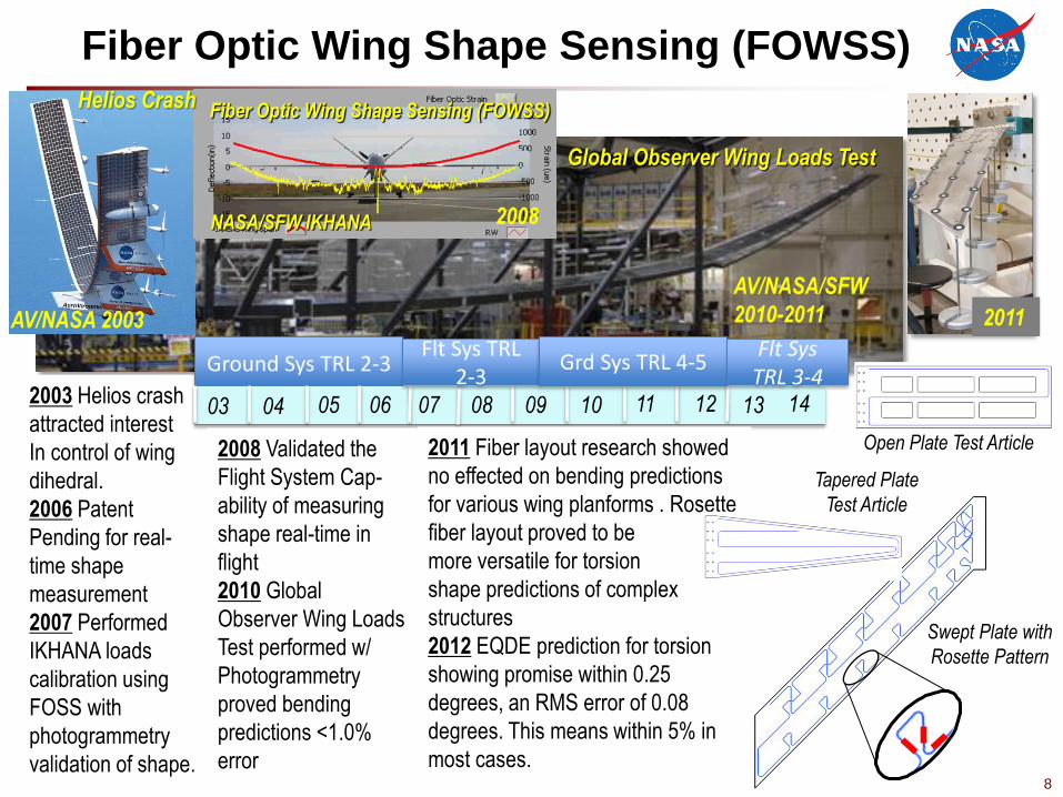
Fiber Optic Wing Shape Sensing (FOWSS)
Open Plate Test Article
NASA/SFW IKHANA
Fiber Optic Wing Shape Sensing (FOWSS) Helios Crash
2008
2011 AV/NASA 2003
2003 Helios crash
attracted interest
In control of wing
dihedral.
2006 Patent
Pending for real-
time shape
measurement
2007 Performed
IKHANA loads
calibration using
FOSS with
photogrammetry
validation of shape.
Ground Sys TRL 2-3
03 04 05 06 07 08 09 10 11 12 13 14
Flt Sys TRL 2-3
Grd Sys TRL 4-5
Global Observer Wing Loads Test
2008 Validated the
Flight System Cap-
ability of measuring
shape real-time in
flight
2010 Global
Observer Wing Loads
Test performed w/
Photogrammetry
proved bending
predictions <1.0%
error
AV/NASA/SFW
2010-2011
Swept Plate with
Rosette Pattern
2011 Fiber layout research showed
no effected on bending predictions
for various wing planforms . Rosette
fiber layout proved to be
more versatile for torsion
shape predictions of complex
structures
2012 EQDE prediction for torsion
showing promise within 0.25
degrees, an RMS error of 0.08
degrees. This means within 5% in
most cases.
Flt Sys TRL 3-4
Tapered Plate
Test Article

9
Fundamental Aeronautics Program
Subsonic Fixed Wing Project
Aeroservoelastically Tailored Wings using MDAO
Research Goals/Objectives Use aeroelastic tailoring theory and active
flexible motion control technique to satisfy the
overall strain, aeroelastic and
aeroservoelastic instability requirements
within given flight envelopes
Use curvilinear sparib concept as well as
composite ply angles for aeroelastic tailoring
Approach Simultaneously update structural as well as
control design variables during early design
phase
Design AR10 Wing using object-oriented
MDAO tool
Design scaled AR10 wing using structural
model tuning tool
Design AR14 Wing using Object-Oriented
MDAO tool
Design scaled AR14 wing using structural
model tuning tool
X-56A
Aeroelastic stability envelope
Equ
iva
len
t Sp
eed
Flutter Boundary
VD 1.15VD
1.0 0.5
Mach Use Aeroelastic Tailoring Up to the Vd line Use Aeroservoelastic
Tailoring above Vd
Curvilinear sparibs

10
Fundamental Aeronautics Program
Subsonic Fixed Wing Project
Baseline FEM
Start w/aspect ratio=10
Static structural &
AE analysis
ID tailoring approaches
State-of-the-art assessment - aeroelastic tailoring
ID optimization strategy & constraints
Design of experiments –
structural AE tailoring
sensitivity analysis
DESIGN
TEST
BACKGROUND
Full scale design
Structural panel testing w/integrated fiber optics
Dynamic scaled X-56A
test
w/fiber optic shape sensing
Passive Aeroelastic Tailored High Aspect Ratio Wings
Add novel control
effectors
Optimization
NEXT STEP = increase aspect
ratio to 14
11
Fundamental Aeronautics Program
Subsonic Fixed Wing Project
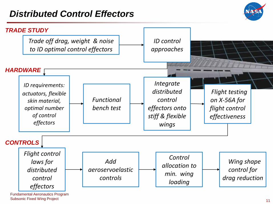
ID requirements:
actuators, flexible skin material,
optimal number of control effectors
Functional bench test
Trade off drag, weight & noise to ID optimal control effectors
HARDWARE
CONTROLS
TRADE STUDY
Flight control laws for
distributed control
effectors
Add aeroservoelastic
controls
Control allocation to min. wing
loading
Wing shape control for
drag reduction
Distributed Control Effectors
ID control approaches
Integrate distributed
control effectors onto stiff & flexible
wings
Flight testing on X-56A for flight control effectiveness

12
Fundamental Aeronautics Program
Subsonic Fixed Wing Project
Focused System’s Research Objectives
1. Provide non-proprietary NASA designed flight control system for
X-56A vehicle – emphasize open source publication
2. Develop robustness criteria for actively controlled flexible vehicles
3. Integrate emerging sensor technology such as FOSS and LESP as
feedback to the flight control system
4. Demonstrate compact FOSS system in flight environment
- In work: Compact FO System, Fiber-Based Ring Laser, Optics on a
Chip, Ruggedizing Fiber, Twist Shape Prediction, Adaptive Spatial
Density Algorithm using Continuous Grading Fiber, 3-core fiber
manufacturing
5. Use FOSS and LESP flight measurements to validate and improve
the MDAO analysis and prediction capability
6. Demonstrate ability to derive onboard in real time, shape and load
information from the FOSS system
7. Using MDAO, design, fabricate, and flight demonstrate an
integrated dynamically scaled wing structure with distributed
sensor and control effectors
13
Fundamental Aeronautics Program
Subsonic Fixed Wing Project
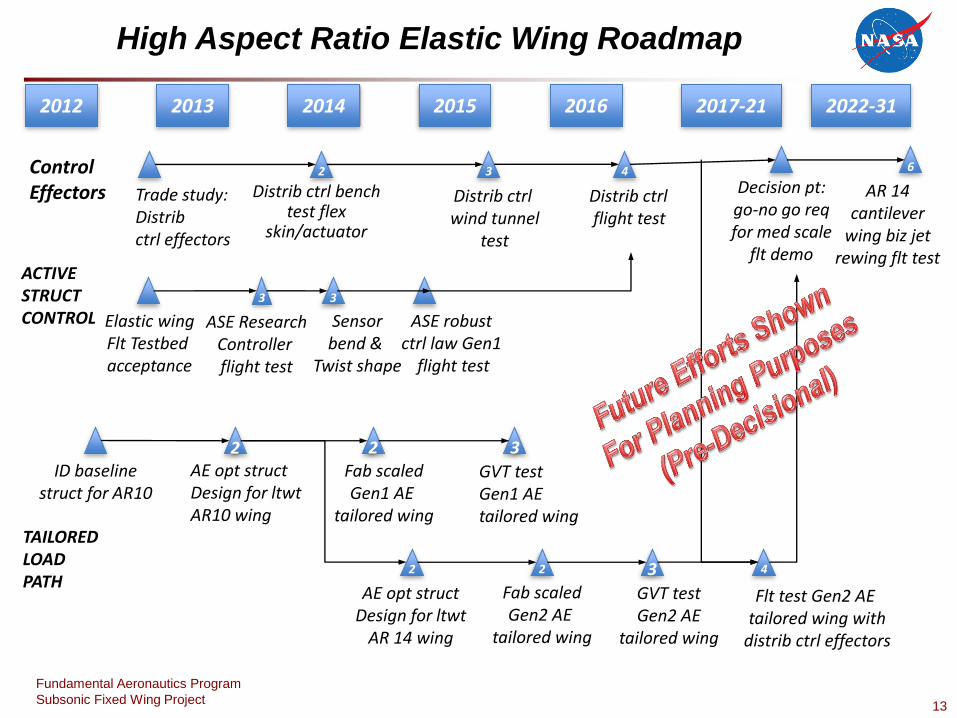
High Aspect Ratio Elastic Wing Roadmap
2012 2013 2014 2015 2016 2017-21 2022-31
Decision pt: go-no go req for med scale
flt demo
6
AR 14 cantilever
wing biz jet rewing flt test
ACTIVE STRUCT CONTROL
Distrib ctrl bench test flex
skin/actuator
2
Distrib ctrl wind tunnel
test
3
Trade study: Distrib ctrl effectors
Distrib ctrl flight test
4
2 AE opt struct Design for ltwt AR10 wing
4
Flt test Gen2 AE tailored wing with
distrib ctrl effectors
3
GVT test Gen1 AE tailored wing
TAILORED LOAD PATH
AE opt struct Design for ltwt
AR 14 wing
2
Fab scaled Gen1 AE
tailored wing
2
Fab scaled Gen2 AE
tailored wing
2 3
GVT test Gen2 AE
tailored wing
ID baseline struct for AR10
Elastic wing Flt Testbed acceptance
Sensor bend &
Twist shape
3
ASE robust ctrl law Gen1
flight test
3
ASE Research Controller flight test
Control Effectors
14
Fundamental Aeronautics Program
Subsonic Fixed Wing Project
Multi-Utility Aeroelastic Demonstration (MAD)
Objectives
• Develop a Multi Utility Technology Test-bed (MUTT) vehicle
that can be utilized in flight research of active aeroelastic
control technologies and Gust Load Alleviation.
• The approach here would be to reduce scale (and cost) and
use the vehicle to validate tools and concepts that could be
applied to larger future vehicles.
• For example, Boeing’s 747-8 has a wing span of 224ft, but the
MUTT is only 28 ft. While it is not truly aeroelastically scaled,
it does exhibit the aeroelastic phenomena of the larger highly
flexible future transport vehicle and is useful for validating
design and analysis methods that could then be applied to
future transports.
• The MUTT vehicle will be capable of performing High Risk
Flight Demonstrations using a certified drogue shoot recovery
system.
• On Jan 2012 MUTT was given the designation of X-56A
15
Fundamental Aeronautics Program
Subsonic Fixed Wing Project
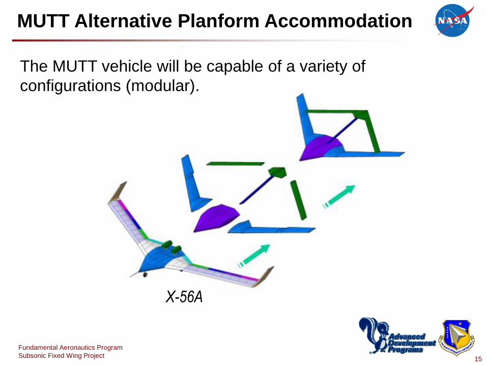
MUTT Alternative Planform Accommodation
The MUTT vehicle will be capable of a variety of
configurations (modular).
X-56A
16
Fundamental Aeronautics Program
Subsonic Fixed Wing Project
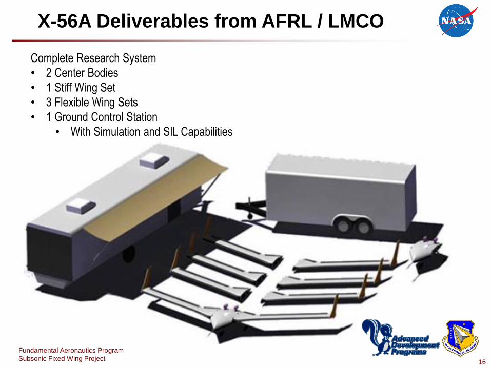
X-56A Deliverables from AFRL / LMCO
Complete Research System
• 2 Center Bodies
• 1 Stiff Wing Set
• 3 Flexible Wing Sets
• 1 Ground Control Station
• With Simulation and SIL Capabilities
17
Fundamental Aeronautics Program
Subsonic Fixed Wing Project
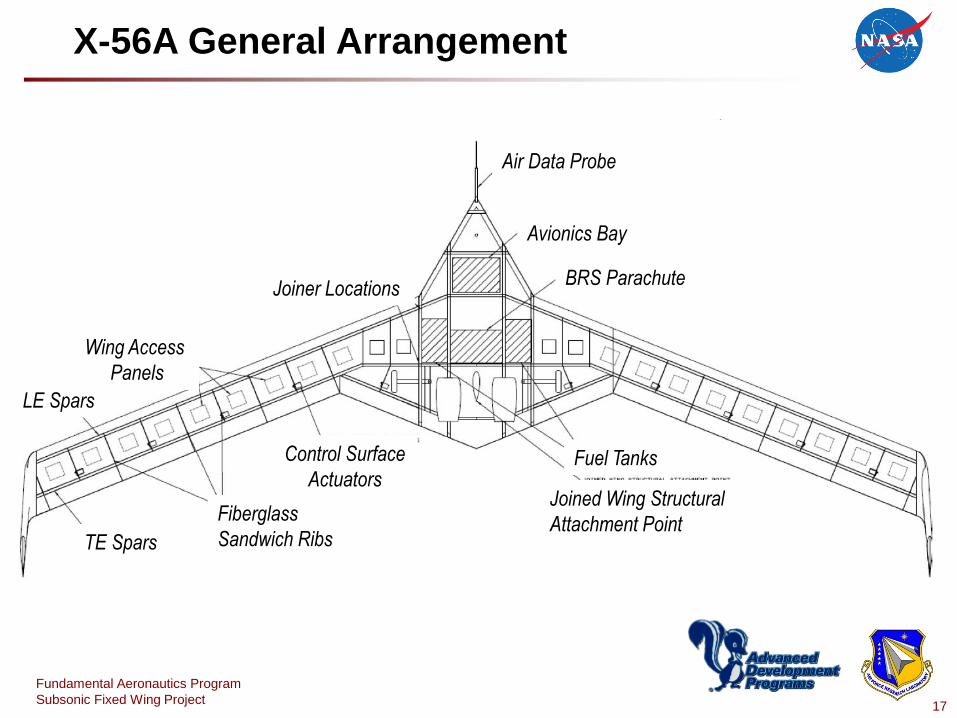
X-56A General Arrangement
Air Data Probe
Avionics Bay
BRS Parachute Joiner Locations
Wing Access
Panels
LE Spars
TE Spars
Fiberglass
Sandwich Ribs
Control Surface
Actuators Fuel Tanks
Joined Wing Structural
Attachment Point

18
Fundamental Aeronautics Program
Subsonic Fixed Wing Project
X-56A
BY:
Jeff Beranek, Lee Nicolai,
Mike Buonanno, Edward Burnett,
Christopher Atkinson, Brian Holm-Hansen
(Lockheed Martin Aeronautics Co., Palmdale, California,) and
Pete Flick
Air Force Research Laboratory, Wright-Patterson Air Force Base, OH
AIAA 2010-9350
Conceptual Design of a Multi-utility Aeroelastic Demonstrator

Your Title Here 19