flextray cable management - cooper crouse-hinds · drop out fitting & cable drop out . . . . ....
TRANSCRIPT

FLEXTRAY™It’s Simple Cable ManagementCatalog & Product Installation GuideCBFT-10
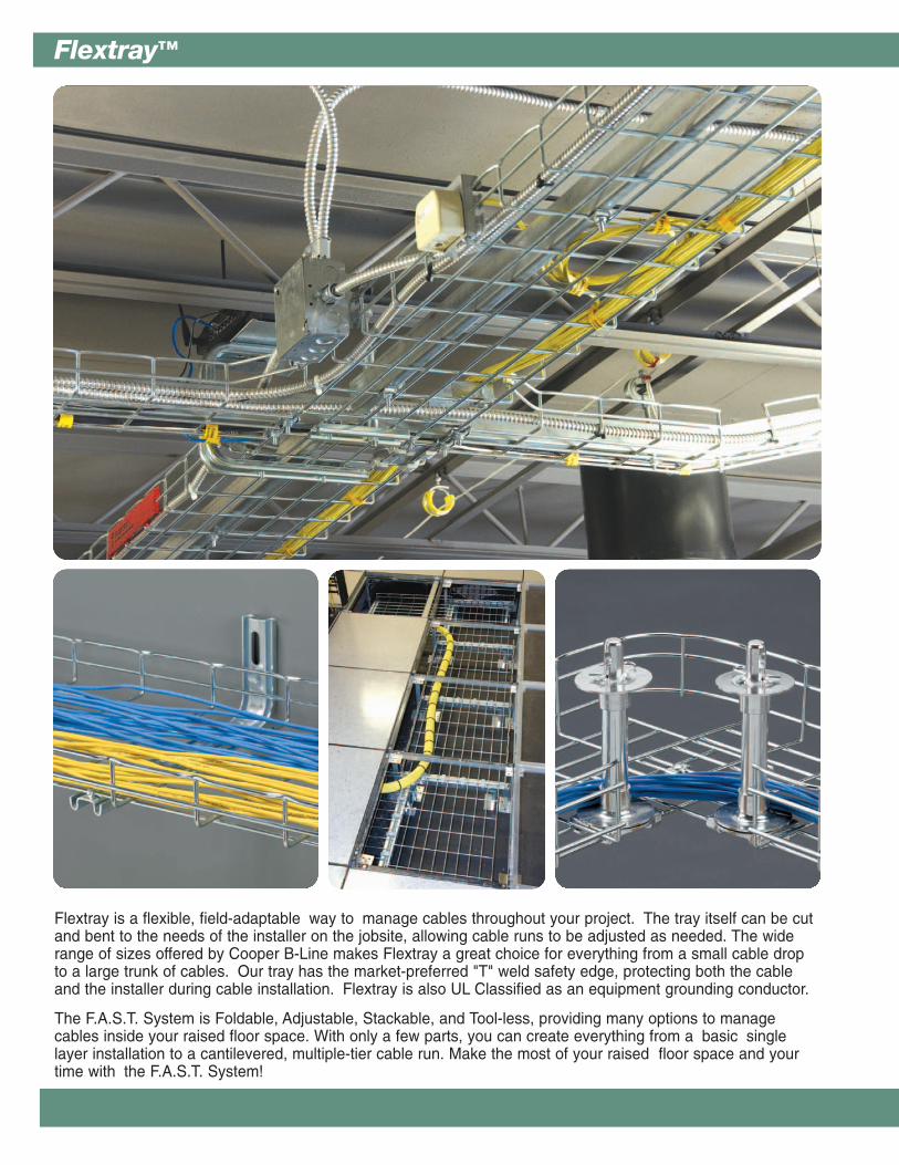
Flextray is a flexible, field-adaptable way to manage cables throughout your project. The tray itself can be cutand bent to the needs of the installer on the jobsite, allowing cable runs to be adjusted as needed. The widerange of sizes offered by Cooper B-Line makes Flextray a great choice for everything from a small cable dropto a large trunk of cables. Our tray has the market-preferred "T" weld safety edge, protecting both the cableand the installer during cable installation. Flextray is also UL Classified as an equipment grounding conductor.
The F.A.S.T. System is Foldable, Adjustable, Stackable, and Tool-less, providing many options to managecables inside your raised floor space. With only a few parts, you can create everything from a basic singlelayer installation to a cantilevered, multiple-tier cable run. Make the most of your raised floor space and yourtime with the F.A.S.T. System!
Flextray™

Flextray™
1
Technical DataFinish & Grounding Information . . . . . . . . . . . 2-3Flextray Load & Fill Chart . . . . . . . . . . . . . . . . . . . 3
Flextray Cable TrayFlextray Straight Sections . . . . . . . . . . . . . . . . . 4-7
Splicing AccessoriesWasher Splices & Components . . . . . . . . . 9-11Flexmate Splice Components . . . . . . . . . . . . . . 11Splice Bars . . . . . . . . . . . . . . . . . . . . . . . . . . . . . . 12-14Hold Down Plate . . . . . . . . . . . . . . . . . . . . . . . . . . . 15Horizontal Adjustable Kit . . . . . . . . . . . . . . . . . . . 1590° Splice Kit . . . . . . . . . . . . . . . . . . . . . . . . . . . . . . . 15Splicing Charts . . . . . . . . . . . . . . . . . . . . . . . . . . . . . 16Splice Plate Kits . . . . . . . . . . . . . . . . . . . . . . . . . . . . 17
Ceiling Support MethodsFlip Clip . . . . . . . . . . . . . . . . . . . . . . . . . . . . . . . . . . . . . 19Trapeze Support . . . . . . . . . . . . . . . . . . . . . . . . . . . 19Center Hanger . . . . . . . . . . . . . . . . . . . . . . . . . . . . . . 20Hold Down Plate . . . . . . . . . . . . . . . . . . . . . . . . . . . 20Mounting Bracket . . . . . . . . . . . . . . . . . . . . . . . . . . . 21Center Hung Clips & Rod Protector . . . . . . . 21Center Trapeze Hanger . . . . . . . . . . . . . . . . . . . . 22KwikWire & Accessories . . . . . . . . . . . . . . . . 23-25
Wall Support MethodsShelf & L Brackets . . . . . . . . . . . . . . . . . . . . . . . . . 27Z Brackets . . . . . . . . . . . . . . . . . . . . . . . . . . . . . . . . . . 28Hold Down Plate . . . . . . . . . . . . . . . . . . . . . . . . . . . 28Attachment Clips . . . . . . . . . . . . . . . . . . . . . . . . . . . 29Mounting Bracket . . . . . . . . . . . . . . . . . . . . . . . . . . . 29Wall Supports . . . . . . . . . . . . . . . . . . . . . . . . . . . . . . 29Wall Termination & Wall Mount Kits . . . . . . . 30C Brackets . . . . . . . . . . . . . . . . . . . . . . . . . . . . . . . . . . 31
F.A.S.T. Under Floor SystemFlextray Sections . . . . . . . . . . . . . . . . . . . . . . . . . . . 33Stands . . . . . . . . . . . . . . . . . . . . . . . . . . . . . . . . . . . . . . 34Cantilever Lits & Accessories . . . . . . . . . . . . . . 35Hold Down & Pedestal Clips . . . . . . . . . . . . . . . 36Cantilever Foot & Under Floor Stand . . . . . 36L Bracket & Toolless Clip . . . . . . . . . . . . . . . . . . 37Pedestal Clamp & Kit . . . . . . . . . . . . . . . . . . . . . . 37Under Floor Support Bracket & U-Bolts . . . 39Ground Bolt, Feet & Adhesive . . . . . . . . . . . . 39Plastic Floor Stand . . . . . . . . . . . . . . . . . . . . . . . . . 39
Flextray AccessoriesCovers . . . . . . . . . . . . . . . . . . . . . . . . . . . . . . . . . . . . . . 41Dividers . . . . . . . . . . . . . . . . . . . . . . . . . . . . . . . . . . . . . 41Solid Bottom Inserts . . . . . . . . . . . . . . . . . . . . . . . . 42Blind Ends . . . . . . . . . . . . . . . . . . . . . . . . . . . . . . . . . . 42Cable Rollers . . . . . . . . . . . . . . . . . . . . . . . . . . . . . . . 43Toolless Clip . . . . . . . . . . . . . . . . . . . . . . . . . . . . . . . . 43Strut Mounting Clip . . . . . . . . . . . . . . . . . . . . . . . . . 43Drop Out Fitting & Cable Drop Out . . . . . . . . 44Conduit Connector . . . . . . . . . . . . . . . . . . . . . . . . . 45Rack Clamp & Adaptor Kit . . . . . . . . . . . . . . . . . 45Radius Shield, Rubber Caps . . . . . . . . . . . . . . 46Touch-Up Paint . . . . . . . . . . . . . . . . . . . . . . . . . . . . . 46Label Clip & Ground Bolt . . . . . . . . . . . . . . . . . . 47Ground Wire Support . . . . . . . . . . . . . . . . . . . . . . 47Threaded Rod & Couplings . . . . . . . . . . . . . . . . 48Hex Nuts, Washers, Beam Clamps
Spring Nuts, Bolted Framing,Concrete-Wood-Steel Rod Anchors . . 48-49
Flextray InstallationsFlextray Cutters . . . . . . . . . . . . . . . . . . . . . . . . . . . . 51Flextray Bender . . . . . . . . . . . . . . . . . . . . . . . . . . . . 52Airshear . . . . . . . . . . . . . . . . . . . . . . . . . . . . . . . . . . . . . 52Angular Bolt Cutters . . . . . . . . . . . . . . . . . . . . . . . . 5390° Horizontal Bends . . . . . . . . . . . . . . . . . . . 54-5690° Horizontal Sweeps . . . . . . . . . . . . . . . . . . . . . 57Reducers . . . . . . . . . . . . . . . . . . . . . . . . . . . . . . . . . . . 58Vertical Inside & Outside Bends . . . . . . . . . . . 58Horizontal Tees & Crosses . . . . . . . . . . . . . . . . . 59Recommended Support Locations . . . . . . . . 60
Flextray Specification2004 Section 16114 -Wire Basket Cable Support System . . 61-62
Flextray IndexIndex . . . . . . . . . . . . . . . . . . . . . . . . . . . . . . . . . . . . 63-64
Table of Contents
Tech
nica
l Dat
a
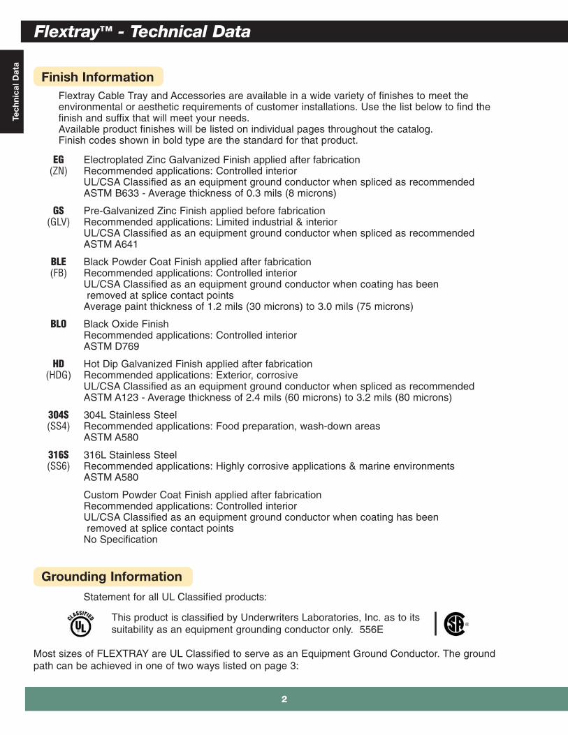
Finish InformationFlextray Cable Tray and Accessories are available in a wide variety of finishes to meet theenvironmental or aesthetic requirements of customer installations. Use the list below to find thefinish and suffix that will meet your needs.Available product finishes will be listed on individual pages throughout the catalog.Finish codes shown in bold type are the standard for that product.
EG Electroplated Zinc Galvanized Finish applied after fabrication(ZN) Recommended applications: Controlled interior
UL/CSA Classified as an equipment ground conductor when spliced as recommendedASTM B633 - Average thickness of 0.3 mils (8 microns)
GS Pre-Galvanized Zinc Finish applied before fabrication(GLV) Recommended applications: Limited industrial & interior
UL/CSA Classified as an equipment ground conductor when spliced as recommendedASTM A641
BLE Black Powder Coat Finish applied after fabrication(FB) Recommended applications: Controlled interior
UL/CSA Classified as an equipment ground conductor when coating has beenremoved at splice contact points
Average paint thickness of 1.2 mils (30 microns) to 3.0 mils (75 microns)
BLO Black Oxide Finish Recommended applications: Controlled interior ASTM D769
HD Hot Dip Galvanized Finish applied after fabrication(HDG) Recommended applications: Exterior, corrosive
UL/CSA Classified as an equipment ground conductor when spliced as recommendedASTM A123 - Average thickness of 2.4 mils (60 microns) to 3.2 mils (80 microns)
304S 304L Stainless Steel(SS4) Recommended applications: Food preparation, wash-down areas
ASTM A580
316S 316L Stainless Steel(SS6) Recommended applications: Highly corrosive applications & marine environments
ASTM A580
Custom Powder Coat Finish applied after fabricationRecommended applications: Controlled interiorUL/CSA Classified as an equipment ground conductor when coating has beenremoved at splice contact points
No Specification
Grounding Information
Statement for all UL Classified products:
This product is classified by Underwriters Laboratories, Inc. as to itssuitability as an equipment grounding conductor only. 556E
Most sizes of FLEXTRAY are UL Classified to serve as an Equipment Ground Conductor. The groundpath can be achieved in one of two ways listed on page 3:
Flextray™ - Technical Data
2

3
Flextray Series Support Span / Loading Capacity* Cable Fill (50% fill)** Part Size Lbs/Ft (max) Actual Area Inside Number of CAT Number of
Number height x width 5'-0” 6'-0” 7'-0” 8'-0” Tray (in2) 5e Cables*** CAT 6 Cables***
FT1.5X12 11/2” x 12” 29 17 14 11 12.2 176 124
FT2X2 2” x 2” 34 28 24 20 4.3 61 43FT2X4 2” x 4” 52 43 35 27 8.2 118 83FT2X6 2” x 6” 66 47 35 27 12.1 175 123FT2X8 2” x 8” 66 47 35 27 16.1 231 163
FT2X12 2” x 12” 68 47 35 27 23.9 345 243FT2X16 2” x 16” 68 47 35 27 31.8 459 324FT2X18 2” x 18” 68 47 35 27 35.8 516 364FT2X20 2” x 20” 68 47 35 27 39.7 573 404
FT2X24 2” x 24” 68 47 35 27 47.5 686 484FT2X30 2” x 30” 68 47 35 27 59.8 862 608FT2X32 2” x 32” 77 53 39 30 63.3 914 645
FT4X4 4” x 4” 58 49 42 36 15.8 227 160FT4X6 4” x 6” 93 77 60 46 23.6 341 240FT4X8 4” x 8” 94 78 61 47 31.5 454 321FT4X12 4” x 12” 119 83 61 47 47.5 686 484FT4X16 4” x 16” 119 83 61 47 63.5 917 647
FT4X18 4” x 18” 119 83 61 47 71.5 1032 728FT4X20 4” x 20” 119 83 61 47 79.5 1148 810FT4X24 4” x 24” 128 89 65 50 95.5 1379 973FT4X30 4” x 30” 128 89 65 50 119.5 1725 1217
FT6X8 6” x 8” 111 77 57 43 47.3 682 481FT6X12 6” x 12” 124 86 63 48 71.6 1034 729FT6X16 6” x 16” 128 89 65 50 95.3 1375 970
FT6X18 6” x 18” 128 89 65 50 107.3 1549 1092FT6X20 6” x 20” 141 98 72 55 118.9 1716 1211FT6X24 6” x 24” 154 107 78 60 143.3 2068 1459
Grounding Information (cont.)
Load & Fill Chart
* Published load chart has not been tested with Flexmate splice. Please consult the factory for load information when using the Flexmate option.
** Flextray fill capacity is based on NEC allowable fill of 50%. The NEC rule requires that the cable cross-sectional areas together may not exceed 50% of the tray area (width x depth = fill). Cables will nearly completely fill the cable tray when reaching the 50% cable fill, due to empty space between the surface of the cables. TIA recommends 40% fill ratio. Flextray loads shown in the loading chart will not be exceeded at 50% fill.
*** CAT 5e 4-pr non-plenum approximated at .21 in. diameter, CAT 6 4-pr non-plenum approximated at .25 in. diameter. Actualdiameters vary by cable manufacturer.
1. Use the recommended quantity of UL Classified splices to connect sections and atplaces where the tray is cut.
2. Run an appropriately sized ground wire alongside the tray and attach it to each traysection and on both sides of a cut in the tray. (This method is recommended byNEMA VE-2 Installation Manual.)
Flextray™ - Technical DataTechnical D
ata

Str
aig
ht S
ecti
ons
FLEXTRAY’s design offers you more
Safety EdgeFLEXTRAY offers the “T” weld
safety edge, which protectsboth the cable and the installer
while installing cables.
Stronger ConstructionFLEXTRAY utilizes the largest
gauge steel in the industry.196” (5mm) diameter minimum.
Tray strength is governed by wiresize and stronger material means
stronger trays.
Clean Smooth CutsOnly FLEXTRAY delivers the
patented Cleanshear® cutting toolproviding smooth edges and
protecting your cable investment.
Flextray™ - Straight Sections
4

Straig
ht Sectio
ns
5
Union Made In The USAFLEXTRAY is Union made in
the U.S.A.
Most UL Classified Tray SizesFLEXTRAY meets UL grounding
requirements. Save time andmoney with UL Classified Flextray
and splices!
Largest RangeOf Sizes Available
FLEXTRAY offers depths of11/2” (38mm) to 6” (152mm) and
widths up to 32” (813mm).
Flextray™ - Straight Sections
Str
aig
ht S
ecti
ons
See page - 2 for finish information
Part Width Wt. Per Pc.
Number in. mm lbs. kg
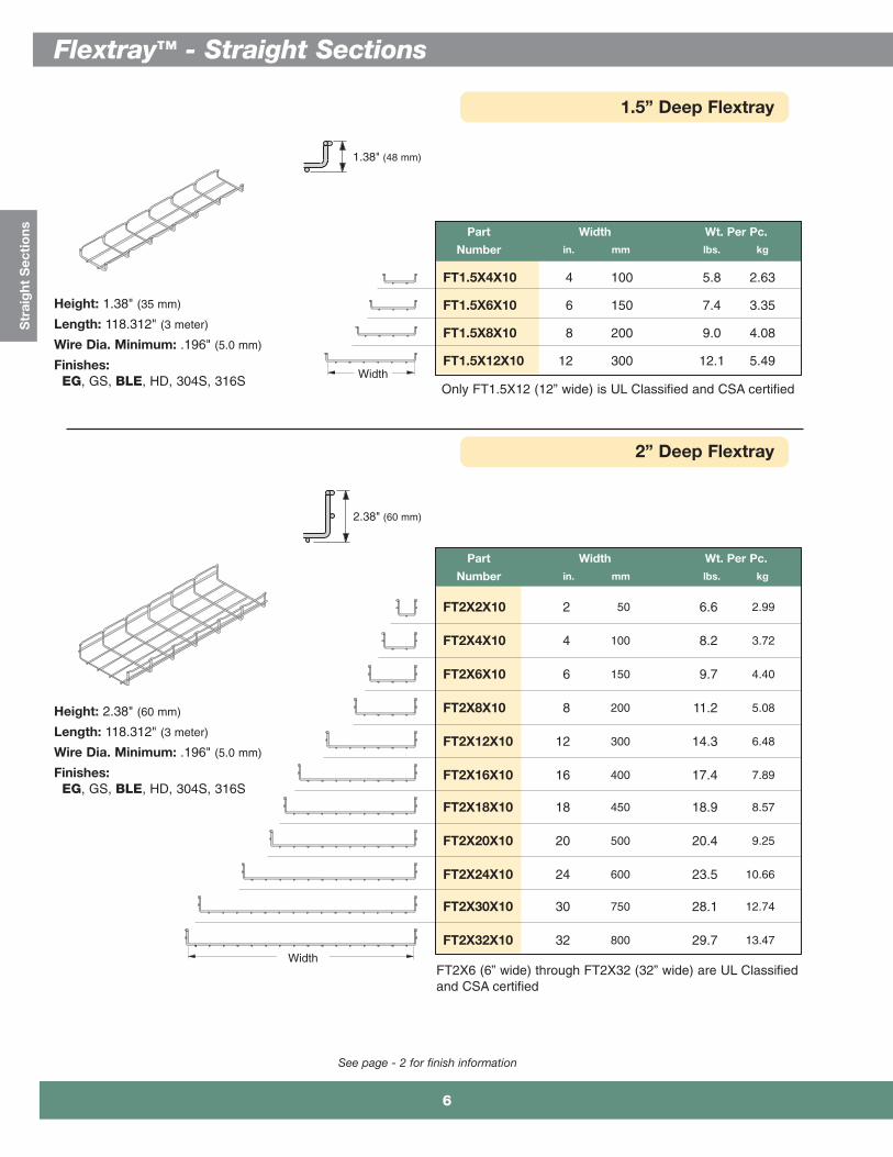
FT2X2X10 2 50 6.6 2.99
FT2X4X10 4 100 8.2 3.72
FT2X6X10 6 150 9.7 4.40
FT2X8X10 8 200 11.2 5.08
FT2X12X10 12 300 14.3 6.48
FT2X16X10 16 400 17.4 7.89
FT2X18X10 18 450 18.9 8.57
FT2X20X10 20 500 20.4 9.25
FT2X24X10 24 600 23.5 10.66
FT2X30X10 30 750 28.1 12.74
FT2X32X10 32 800 29.7 13.47
2” Deep Flextray
Height: 2.38" (60 mm)
Length: 118.312" (3 meter)
Wire Dia. Minimum: .196" (5.0 mm)
Finishes:EG, GS, BLE, HD, 304S, 316S
2.38" (60 mm)
Part Width Wt. Per Pc.
Number in. mm lbs. kg
FT1.5X4X10 4 100 5.8 2.63
FT1.5X6X10 6 150 7.4 3.35
FT1.5X8X10 8 200 9.0 4.08
FT1.5X12X10 12 300 12.1 5.49
1.5” Deep Flextray
Width
Height: 1.38" (35 mm)
Length: 118.312" (3 meter)
Wire Dia. Minimum: .196" (5.0 mm)
Finishes:EG, GS, BLE, HD, 304S, 316S
1.38" (48 mm)
WidthOnly FT1.5X12 (12” wide) is UL Classified and CSA certified
FT2X6 (6” wide) through FT2X32 (32” wide) are UL Classified and CSA certified
Flextray™ - Straight Sections
6

Straig
ht Sectio
ns
See page - 2 for finish information
6” Deep Flextray
6.38"(162 mm)
4” Deep Flextray
Height: 4.38" (111 mm)
Length: 118.312" (3 meter)
Wire Diameter Minimum:.196" (5.0 mm)
Finishes:EG, GS, BLE, HD,304S, 316S
Part Width Wt. Per Pc.Number in. mm lbs. kg
FT4X4X10 4 100 11.25 5.10
FT4X6X10 6 150 12.79 5.80
FT4X8X10 8 200 14.32 6.49
FT4X12X10 12 300 17.39 7.89
FT4X16X10 16 400 20.45 9.27
FT4X18X10 18 450 21.99 9.97
FT4X20X10 20 500 23.52 10.67
FT4X24X10 24 600 26.59 12.06
FT4X30X10 30 750 31.19 14.15
4.38"(111 mm)
Width
Height: 6.38" (162 mm)
Length: 118.312" (3 meter)
Wire Diameter Minimum:.196" (5.0 mm)
Finishes:EG, GS, BLE, HD,304S, 316S
Part Width Wt. Per Pc.Number in. mm lbs. kg
FT6X8X10 8 200 17.39 7.89
FT6X12X10 12 300 20.45 9.27
FT6X16X10 16 400 23.52 10.67
FT6X18X10 18 450 25.06 11.37
FT6X20X10 20 500 26.59 12.06
FT6X24X10 24 600 29.66 13.45
WidthAll 6” deep Flextrays are UL Classified and CSA certified
All 4” deep Flextrays are UL Classified and CSA certified
7
Flextray™ - Straight Sections

Spl
icin
g A
cces
sorie
s
Flextray™ - Splicing Accessories
8

Splicing A
ccessories
Splice Hardware Components
Washer Splice Kit
See page 2 for finish and grounding information
Part Description Qty./Box Wt./Box
Number lbs. kg
WASHER SPL KIT__ Assembly of 50 4.5 2.04Staked WasherStud/Washer& Finned Nut
• Washer is staked to bolt, holding part stationary during installation
• Fewer parts to handle• For use with all tray widths and sizes• Finishes __: EG, BLE
Part Description Qty./Box Wt./Box
Number lbs. kg
1/4” x 1”FTHDWE 1/4__ Carriage Bolt & 50 1.2 0.54
Finned nut
1” SquareTOP WASHER__ Splice Washer 50 1.4 0.63
13/16” SquareBTM WASHER __ Splice Washer 50 2.0 0.91
• Works with all splicing needs• For use with all tray widths and sizes• Components are sold separately• Finishes __: EG, BLE-BLO, 304S, 316S
Tray Height Tray Width - number of splices2” 4” 6” 8” 12” 16” 18” 20” 24”
(50mm) (100mm) (150mm) (200mm) (300mm) (400mm) (450mm) (500mm) (600mm)
2” NC NC 4 4 4 4 4 5 54” NM 4 5 6 6 7 7 7 86” NM NM NM 6 6 7 7 7 8
Splicing Chart (number of splices required for UL Classification)
FTHDWE1/4BTM WASHER TOP WASHER
BLE suffix indicates blackzinc finish for this part only
FTHDWE 1/4 not available in BLE.
TOP WASHER & BTM WASHERnot available in BLO.
Tray Height Tray Width - number of splices2” 4” 6” 8” 12” 16” 18” 20” 24”
(50mm) (100mm) (150mm) (200mm) (300mm) (400mm) (450mm) (500mm) (600mm)
2” NC NC 4 4 4 4 4 5 54” NM 4 5 6 6 7 7 7 86” NM NM NM 6 6 7 7 7 8
Splicing Chart (number of splices required for UL Classification)
NC = Not UL Classified in this size NM = Flextray is not manufactured in this size
NC = Not UL Classified in this size NM = Flextray is not manufactured in this size
9
Flextray™ - Splicing Accessories
Spl
icin
g A
cces
sorie
s
Wing Splice™
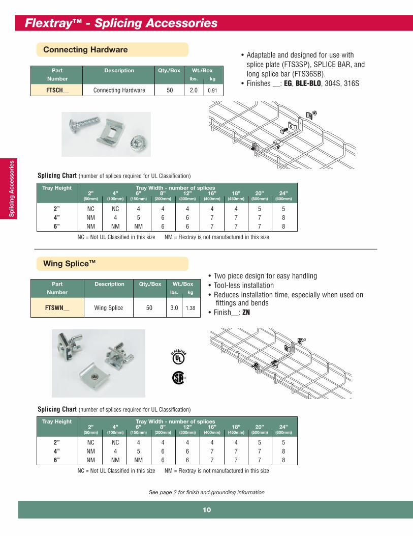
Connecting Hardware• Adaptable and designed for use with
splice plate (FTS3SP), SPLICE BAR, andlong splice bar (FTS36SB).
• Finishes __: EG, BLE-BLO, 304S, 316S
Part Description Qty./Box Wt./Box
Number lbs. kg
FTSWN__ Wing Splice 50 3.0 1.38
• Two piece design for easy handling• Tool-less installation• Reduces installation time, especially when used on
fittings and bends• Finish__: ZN
Part Description Qty./Box Wt./Box
Number lbs. kg
FTSCH__ Connecting Hardware 50 2.0 0.91
Tray Height Tray Width - number of splices2” 4” 6” 8” 12” 16” 18” 20” 24”
(50mm) (100mm) (150mm) (200mm) (300mm) (400mm) (450mm) (500mm) (600mm)
2” NC NC 4 4 4 4 4 5 54” NM 4 5 6 6 7 7 7 86” NM NM NM 6 6 7 7 7 8
Splicing Chart (number of splices required for UL Classification)
NC = Not UL Classified in this size NM = Flextray is not manufactured in this size
See page 2 for finish and grounding information
Flextray™ - Splicing Accessories
10
Splicing A
ccessories
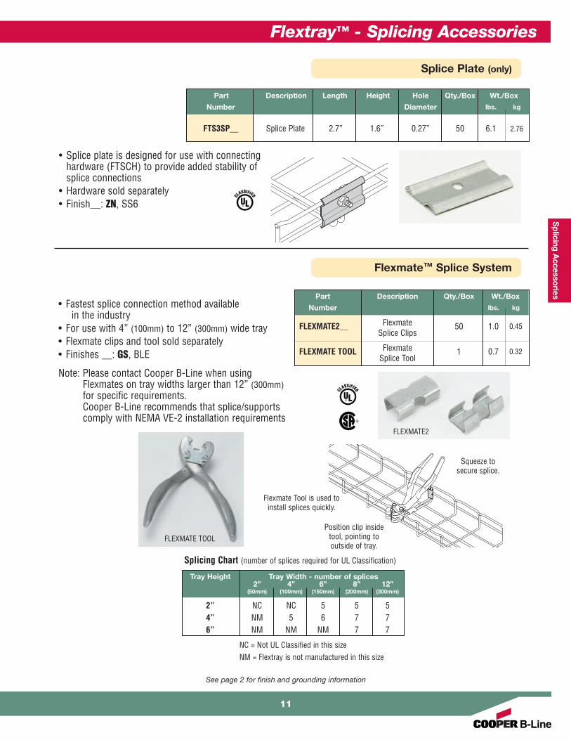
Splice Plate (only)
Flexmate™ Splice System
Part Description Qty./Box Wt./Box
Number lbs. kg
FLEXMATE2__ Flexmate 50 1.0 0.45Splice Clips
FLEXMATE TOOL Flexmate 1 0.7 0.32Splice Tool
Tray Height Tray Width - number of splices2” 4” 6” 8” 12”
(50mm) (100mm) (150mm) (200mm) (300mm)
2” NC NC 5 5 54” NM 5 6 7 76” NM NM NM 7 7
• Fastest splice connection method availablein the industry
• For use with 4” (100mm) to 12” (300mm) wide tray• Flexmate clips and tool sold separately• Finishes __: GS, BLE
Note: Please contact Cooper B-Line when usingFlexmates on tray widths larger than 12” (300mm)for specific requirements.Cooper B-Line recommends that splice/supportscomply with NEMA VE-2 installation requirements
Splicing Chart (number of splices required for UL Classification)
Flexmate Tool is used toinstall splices quickly.
Position clip insidetool, pointing tooutside of tray.
Squeeze tosecure splice.
FLEXMATE2
FLEXMATE TOOL
NC = Not UL Classified in this sizeNM = Flextray is not manufactured in this size
Part Description Length Height Hole Qty./Box Wt./Box
Number Diameter lbs. kg
FTS3SP__ Splice Plate 2.7” 1.6” 0.27” 50 6.1 2.76
• Splice plate is designed for use with connectinghardware (FTSCH) to provide added stability of splice connections
• Hardware sold separately• Finish__: ZN, SS6
See page 2 for finish and grounding information
11
Flextray™ - Splicing Accessories

Spl
icin
g A
cces
sorie
s
Tab-Loc Connector
Part Description Length Qty./Box Wt./Box
Number lbs. kg
FTSTLC__ Tab-Loc 9.29” 50 7.2 3.26Connectors
• Fast splice for straight runs of tray• For use with 2” (50mm) to 32” (800mm) wide tray
to connect straight sections only• Finishes __: ZN, SS6
Application Requirements
Tab-Loc security without special tools.
Step 1 Step 3Step 2
Step 4
The recommendations listed are equal for all depths(except as noted).
Installation
Screwdriver can also be used tobend tab-locs (hold connector endswhile bending).
Tray Height Tray Width - number of splices2” 4” 6” 8” 12” 16” 18” 20” 24”
(50mm) (100mm) (150mm) (200mm) (300mm) (400mm) (450mm) (500mm) (600mm)
2” NC NC 4 4 4 4 4 5 54” NM 4 5 6 6 7 7 7 86” NM NM NM 6 6 7 7 7 8
Splicing Chart (number of splices required for UL Classification)
NC = Not UL Classified in this size NM = Flextray is not manufactured in this size
See page 2 for finish and grounding information
Flextray™ - Splicing Accessories
12

Splicing A
ccessories
See page 2 for finish and grounding information
Splice Bar
Part Description Qty./Box Wt./Box
Number lbs. kg
SPLICE BAR__ 1013/16” Long Bar 50 14.0 6.35
• Adds rigidity to washer splice methods• Used on side rails only (not for use in tray bottom)• For use on trays when using splice hardware FTSCH• Hardware sold separately• Finishes __: EG, BLE, HD, 316S
Each splice bar requires three (3) each of Hardware Splice Components -TOP WASHER, and FTHDWE 1/4 to complete connection.
These items must be ordered separately.
Washer Splice Kits (WASHER SPL KIT) are required for connections on bottom of tray.
Hardware is not sold withsplice bar.
Tray Height Tray Width - number of splices2” 4” 6” 8” 12” 16” 18” 20” 24”
(50mm) (100mm) (150mm) (200mm) (300mm) (400mm) (450mm) (500mm) (600mm)
2” NC NC 2 2 2 2 2 2 24” NM 4 4 4 4 4 4 4 46” NM NM NM 4 4 4 4 4 4
Splicing Chart (number of splices required for UL Classification)
NC = Not UL Classified in this size NM = Flextray is not manufactured in this size
13
Flextray™ - Splicing Accessories
Spl
icin
g A
cces
sorie
s
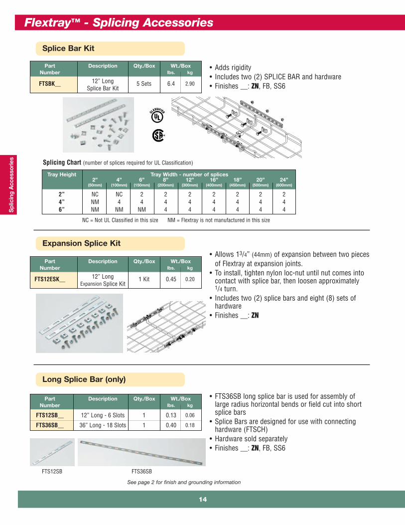
Long Splice Bar (only)
See page 2 for finish and grounding information
Part Description Qty./Box Wt./BoxNumber lbs. kg
FTS12SB__ 12” Long - 6 Slots 1 0.13 0.06
FTS36SB__ 36” Long - 18 Slots 1 0.40 0.18
• FTS36SB long splice bar is used for assembly oflarge radius horizontal bends or field cut into shortsplice bars
• Splice Bars are designed for use with connectinghardware (FTSCH)
• Hardware sold separately• Finishes __: ZN, FB, SS6
Expansion Splice Kit
Part Description Qty./Box Wt./BoxNumber lbs. kg
FTS12ESK__ 12” Long 1 Kit 0.45 0.20Expansion Splice Kit
• Allows 13/4” (44mm) of expansion between two piecesof Flextray at expansion joints.
• To install, tighten nylon loc-nut until nut comes intocontact with splice bar, then loosen approximately1/4 turn.
• Includes two (2) splice bars and eight (8) sets ofhardware
• Finishes __: ZN
Splice Bar Kit
• Adds rigidity • Includes two (2) SPLICE BAR and hardware• Finishes __: ZN, FB, SS6
Tray Height Tray Width - number of splices2” 4” 6” 8” 12” 16” 18” 20” 24”
(50mm) (100mm) (150mm) (200mm) (300mm) (400mm) (450mm) (500mm) (600mm)
2” NC NC 2 2 2 2 2 2 24” NM 4 4 4 4 4 4 4 46” NM NM NM 4 4 4 4 4 4
Splicing Chart (number of splices required for UL Classification)
NC = Not UL Classified in this size NM = Flextray is not manufactured in this size
Part Description Qty./Box Wt./BoxNumber lbs. kg
FTSBK__ 12” Long 5 Sets 6.4 2.90Splice Bar Kit
FTS12SB FTS36SB
Flextray™ - Splicing Accessories
14

Splicing A
ccessories
Hold Down Plate
See page 2 for finish and grounding information
Horizontal Adjustable Kit• Horizontal adjustable kit can be used to createhorizontal angles from prepared Flextray straightsections
• Conveniently poly-bagged• Finishes __: EG, BLE, 316S
Part Description Qty./Box Wt./Box
Number lbs. kg
FTSHAK__ Horizontal 10 2.4 1.09Adjustable Kit
90 Degree Kit• For fast assembly of 90° turns and tee fittings• For use with all tray widths and sizes• One kit will make two 90° turns or one tee fitting• 90 DEGREE KIT: includes: two (2) 90° splice bars
and eight (8) FTSCH• Finishes __: EG, BLE, 316S
Part Description Qty./Box Wt./Box
Number lbs. kg
90 degree splice90 DEGREE KIT__ bar & hardware 1 1.3 0.59
Part Slot Size Qty./Box Wt./Box
Number lbs. kg
SUPT WASHER__ .28” x .70” 50 4.7 2.13
FTA6HD__ .40” x .70” 50 3.5 1.59
• Easy way to mount 4" (100mm) wide tray forraceway run.
• Use 1/4" screws to attach SUPT WASHER to yourspecific wall/stud application (hardware soldseparately).
• FTA6HD can be used in pairs to create a center-hungsupport using 3/8" rod.
• To protect cables use threadedrod protector (page 61).
• To complete 3/8" center hangerassembly use:
2 - FTA6HD2 - HN 3/8"-16 hex nuts
• Finish: ZN, SS6
15
Flextray™ - Splicing Accessories

Spl
icin
g A
cces
sorie
s
FT2X2 2” 50 2 - - -FT2X4 4” 100 2 - - -FT2X6 6” 150 41 - - -FT2X8 8” 200 41 - - -FT2X12 12” 300 41 - - -FT2X16 16” 400 41 - - -FT2X18 18” 450 41 - - -FT2X20 20” 500 51 - - -FT2X24 24” 600 51 - - -FT2X30 30” 750 71 - - -FT2X32 32” 800 71 - - -FT4X4 4” 100 41 - - -FT4X6 6” 150 51 - - -FT4X8 8” 200 62 - - -FT(*)X12 12” 300 62 - - -FT(*)X16 16” 400 72 - - -FT(*)X18 18” 450 72 - - -FT(*)X20 20” 500 72 - - -FT(*)X24 24” 600 72 - - -FT(*)X30 30” 750 82 - - -
FT2X2 2” 50 - 2 2 -FT2X4 4” 100 - 2 2 -FT2X6 6” 150 1 2 2 -FT2X8 8” 200 1 2 2 -FT2X12 12” 300 2 2 2 -FT2X16 16” 400 2 2 2 -FT2X18 18” 450 2 2 2 -FT2X20 20” 500 2 2 2 -FT2X24 24” 600 2 2 2 -FT2X30 30” 750 4 2 2 -FT2X32 32” 800 4 2 2 -FT4X4 4” 100 1 2 2 -FT4X6 6” 150 2 2 2 -FT4X8 8” 200 2 2 2 -FT(*)X12 12” 300 3 2 2 -FT(*)X16 16” 400 4 2 2 -FT(*)X18 18” 450 4 2 2 -FT(*)X20 20” 500 4 2 2 -FT(*)X24 24” 600 4 2 2 -FT(*)X30 30” 750 5 2 2 -
FT2X2 2” 50 - 2 - 2FT2X4 4” 100 - 2 - 2FT2X6 6” 150 1 2 - 2FT2X8 8” 200 1 2 - 2FT2X12 12” 300 2 2 - 2FT2X16 16” 400 2 2 - 2FT2X18 18” 450 2 2 - 2FT2X20 21” 500 2 2 - 2FT2X24 24” 600 2 2 - 2FT2X30 30” 750 3 6 - 2FT2X32 32” 800 3 6 - 2FT4X4 4” 100 1 2 - 2FT4X6 6” 150 2 2 - 2FT4X8 8” 200 2 6 - 2FT(*)X12 12” 300 2 6 - 2FT(*)X16 16” 400 3 6 - 2FT(*)X18 18” 450 3 6 - 2FT(*)X20 20” 500 3 6 - 2FT(*)X24 24” 600 3 6 - 2FT(*)X30 30” 750 4 6 - 2
Install splice bars on sides andWASHER SPL KIT on bottom.
Install splice plates on sides andWASHER SPL KIT on bottom.
1 Install one kit on each side and remaining kit(s) on bottom.2 Install two kits on each side and remaining kits on bottom.
Washer Splice Kits
Splice Plates
Splice Bars
System System Connector Connecting Splice SplicePart Width Assembly Hardware Plate Bar
Number in. mm WASHER SPL KIT FTSCH FTS3SP SPLICE BAR
(*) 4 for 4” Deep Flextray6 for 6” Deep Flextray
Components Required to Connect Two Sections of Flextray
Flextray™ - Splicing Accessories
16
Splicing A
ccessories
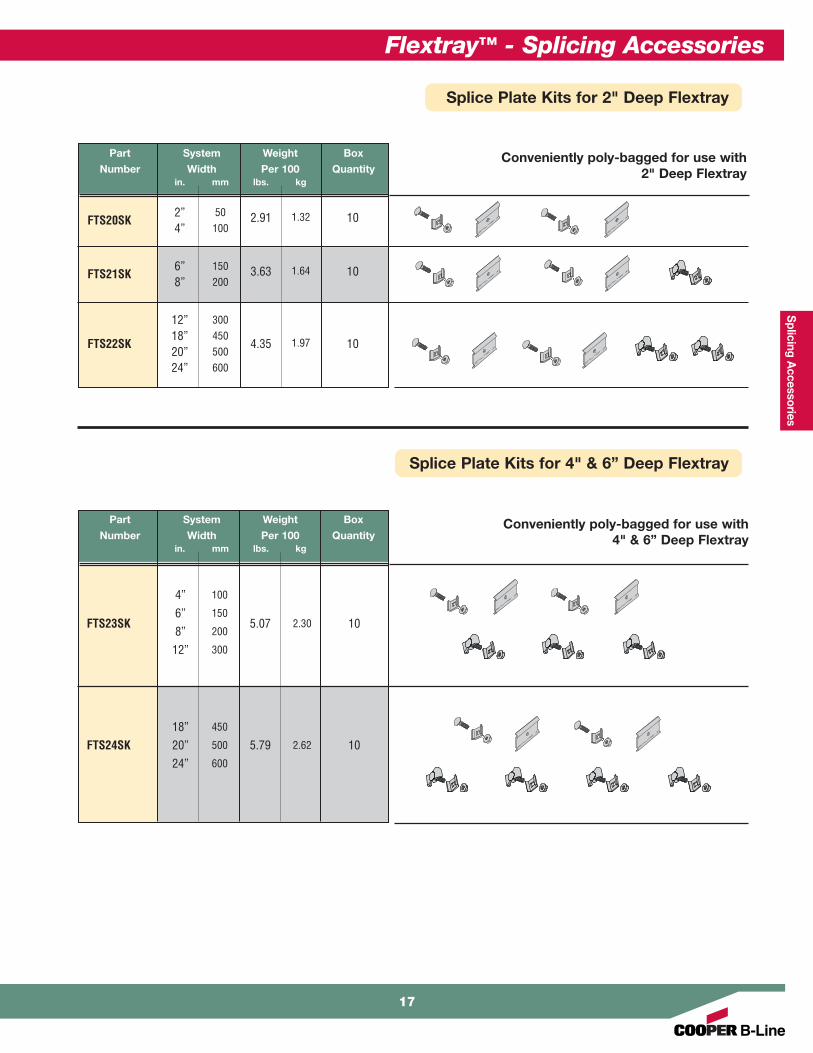
Part System Weight Box
Number Width Per 100 Quantityin. mm lbs. kg
FTS20SK2” 50 2.91 1.32 104” 100
FTS21SK6” 150 3.63 1.64 108” 200
12” 300
FTS22SK18” 450
4.35 1.97 1020” 50024” 600
Conveniently poly-bagged for use with2" Deep Flextray
Conveniently poly-bagged for use with 4" & 6” Deep Flextray
Part System Weight Box
Number Width Per 100 Quantityin. mm lbs. kg
4” 100
6” 150FTS23SK
8” 2005.07 2.30 10
12” 300
18” 450
FTS24SK 20” 500 5.79 2.62 1024” 600
Splice Plate Kits for 2" Deep Flextray
Splice Plate Kits for 4" & 6” Deep Flextray
17
Flextray™ - Splicing Accessories
Cei
ling
Sup
po
rts
Flextray™ - Ceiling Support Methods
18

Ceiling
Sup
po
rts
Flip Clip™
Part Description Qty./Box Wt./Box
Number lbs. kg
WB46H__ Flip Clip 50 5.2 2.36
• Accommodates 1/4" and 3/8" rod sizes• Installs quickly with a screwdriver or pliers thus
reducing installation time• Requires only one hex nut (not included) to hang
and level the Flextray• Retainer tabs can be bent over to lock-in the
threaded rod and wire basket• Finishes __: ZN, FB, SS6
See page 2 for finish information
Snap retainer stopsin place after cable is
loaded.
Trapeze Support
Part Description Qty./Box Wt./Box
Number lbs. kg
TRAPEZE SUPT2__ Trapeze 50 trapeze clips 7.0 3.17Support Clip 100 retainer stops
• Trapeze Clip installs fast• For use with trays up to 4” (100mm) deep,
12” (300mm) wide, and spans up to 8’-0” (2.44m)• Tray can be released from support to allow side
cable loading• Accepts 1/4” and 3/8” threaded rod sizes• Finishes __: GS, BLE
Snap retainer stopsin place after cable is
loaded.
19
Flextray™ - Ceiling Support Methods
Cei
ling
Sup
po
rts
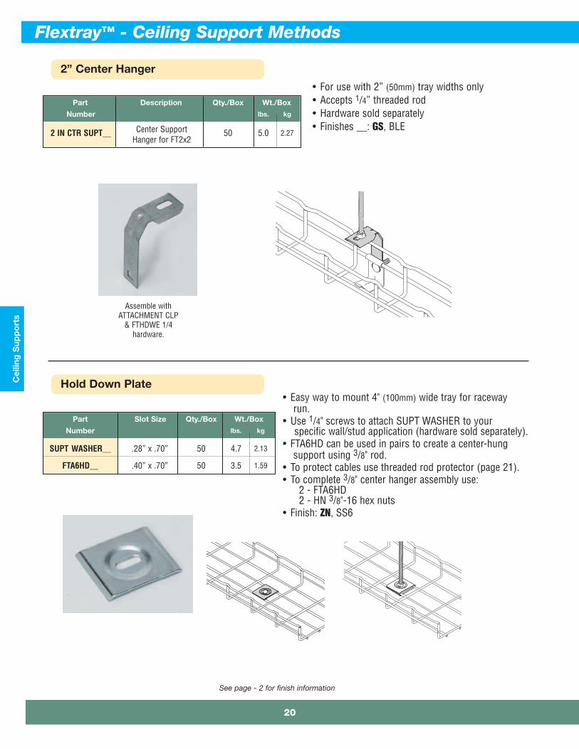
2” Center Hanger
See page - 2 for finish information
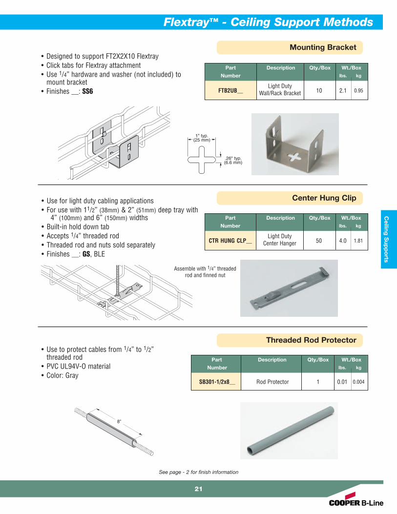
Hold Down Plate
Part Slot Size Qty./Box Wt./Box
Number lbs. kg
SUPT WASHER__ .28” x .70” 50 4.7 2.13
FTA6HD__ .40” x .70” 50 3.5 1.59
• Easy way to mount 4" (100mm) wide tray for racewayrun.
• Use 1/4" screws to attach SUPT WASHER to yourspecific wall/stud application (hardware sold separately).
• FTA6HD can be used in pairs to create a center-hungsupport using 3/8" rod.
• To protect cables use threaded rod protector (page 21).• To complete 3/8" center hanger assembly use:
2 - FTA6HD2 - HN 3/8"-16 hex nuts
• Finish: ZN, SS6
Part Description Qty./Box Wt./Box
Number lbs. kg
2 IN CTR SUPT__ Center Support 50 5.0 2.27Hanger for FT2x2
• For use with 2” (50mm) tray widths only• Accepts 1/4” threaded rod• Hardware sold separately• Finishes __: GS, BLE
Assemble withATTACHMENT CLP
& FTHDWE 1/4hardware.
Flextray™ - Ceiling Support Methods
20
Ceiling
Sup
po
rts
Mounting Bracket
See page - 2 for finish information
Center Hung Clip
Threaded Rod Protector
Part Description Qty./Box Wt./Box
Number lbs. kg
SB301-1/2x8__ Rod Protector 1 0.01 0.004
• Use to protect cables from 1/4” to 1/2”threaded rod
• PVC UL94V-O material• Color: Gray
8”
Part Description Qty./Box Wt./Box
Number lbs. kg
Light DutyCTR HUNG CLP__ Center Hanger 50 4.0 1.81
• Use for light duty cabling applications• For use with 11/2” (38mm) & 2” (51mm) deep tray with
4” (100mm) and 6” (150mm) widths• Built-in hold down tab• Accepts 1/4” threaded rod• Threaded rod and nuts sold separately• Finishes __: GS, BLE
Assemble with 1/4” threadedrod and finned nut
Part Description Qty./Box Wt./Box
Number lbs. kg
Light DutyFTB2UB__ Wall/Rack Bracket 10 2.1 0.95
• Designed to support FT2X2X10 Flextray• Click tabs for Flextray attachment• Use 1/4” hardware and washer (not included) to
mount bracket• Finishes __: SS6
.26" typ.(6.6 mm)
1" typ.(25 mm)
21
Flextray™ - Ceiling Support Methods

Cei
ling
Sup
po
rts
Center Trapeze Hanger
See page - 2 for finish information
• Can be installed as center-hung or traditionaltrapeze hanger
• Multiple options to secure Flextray to hanger- Built in hold down tabs (use screwdriver to
bend down tab)- Compatible with TOOLLESS CLIP with
snap-in locking pin- Compatible with WBUHD hold down clip when
tray crosswire is aligned over top of hanger- Slots and holes for optional hardware
attachment• Corrosion resistant pre-galvanized zinc finish
(other finishes available upon request)• Center hole for up to 1/2” rod• Hole on each end for up to 3/8” rod• Threaded rod protector available (SB301-1/2 x 8)
Center Hung
Trapeze
Part Number Maximum Tray Width Actual Length Wt./Pc.in. mm in. mm lbs. kg
FTB06CT 6” 150 9.78” 248 0.61 0.27
FTB08CT 8” 200 11.75” 298 0.74 0.33
FTB12CT 12” 300 15.69” 398 0.98 0.44
FTB16CT 16” 400 19.63” 498 1.61 0.73
FTB18CT 18” 450 21.59” 548 1.77 0.80
FTB20CT 20” 500 23.56” 598 1.93 0.87
FTB24CT 24” 600 27.50” 698 2.25 1.02
Flextray™ - Ceiling Support Methods
22

Ceiling
Sup
po
rts
KwikWire™ Clamps & Wire Rope
23
Part Clamp Description Qty./Box
Number For Use With Rope Diameter
BKC100 1/32”, 1/16” & 3/32” 100
BKC200 3/32”, 1/8” & 3/16” 50
• KwikWire system replaces jack chain or ATR to support lighting, ductwork, andFlextray.
• Can be quickly installed around beams - No drilling required.• Ideal for sloped ceilings - can hang objects at up to 60° angles.• Simple height adjustments are made by releasing locking tab, no tools required.• Spools of wire can be cut to length in field, reducing waste and up front planning.
(1) 7 x 7
Wire Rope Construction
(2) 7 x 19
Part Rope Diameter Qty./Spool
Number - Working Load
BKW063 (1) 1/16” - 96 lbs. 500 ft.
BKW094 (1) 3/32” - 184 lbs. 500 ft.
BKW125 (1) 1/8” - 340 lbs. 500 ft.
BKW188 (2) 3/16” - 840 lbs. 250 ft.
BKCC Wire Rope Cutter 1
KwikWire™ ClampWorking Loads*
Clamp Wire Lbs.
Part No. Rope SafetyDia. Factor 5
BKC100 1/32” 0-22
BKC100 1/16” 0-75
BKC100 3/32” 25-150
BKC200 3/32” 25-150
BKC200 1/8” 25-250
BKC200 3/16” 50-640
* Working loads shownare for hanging vertically.For suspending at15°, 30°, 45° or 60°angles from vertical, usethe following percentageof the working loads fromthe chart:
15° = 96%30° = 86%45° = 70%60° = 50%
Flextray™ - Ceiling Support Methods

Cei
ling
Sup
po
rts
KwikWire™ Cable Assemblies
• New KwikWire “Y” Cable Assemblies will simplify the installationof light fixtures and cable tray.
• “Y” Cables enable a single suspension point to provide twosecurement points.
• “Y” legs are 18” in length.• “Y” Cable Assembly Kits include two (2) 10’-0” long cable
assemblies and two (2) KwikWire clamps.• Add-on cable assemblies can be field installed on KwikWire
systems.
Part Description Qty./Box
Number
BKYC-094 Carabiner 20
BKYC-094-120K Carabiner 10
BKYC-094
BKYC-094-120K
Flextray™ - Ceiling Support Methods
24
Ceiling
Sup
po
rts
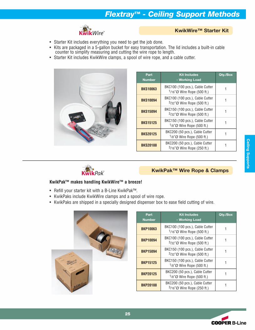
KwikWire™ Starter Kit
• Starter Kit includes everything you need to get the job done.• Kits are packaged in a 5-gallon bucket for easy transportation. The lid includes a built-in cable
counter to simplify measuring and cutting the wire rope to length.• Starter Kit includes KwikWire clamps, a spool of wire rope, and a cable cutter.
Part Kit Includes Qty./Box
Number - Working Load
BKS10063 BKC100 (100 pcs.), Cable Cutter 11/16ӯ Wire Rope (500 ft.)
BKS10094 BKC100 (100 pcs.), Cable Cutter 13/32ӯ Wire Rope (500 ft.)
BKS15094 BKC150 (100 pcs.), Cable Cutter 13/32ӯ Wire Rope (500 ft.)
BKS15125 BKC150 (100 pcs.), Cable Cutter 11/8ӯ Wire Rope (500 ft.)
BKS20125 BKC200 (50 pcs.), Cable Cutter 11/8ӯ Wire Rope (500 ft.)
BKS20188 BKC200 (50 pcs.), Cable Cutter 13/16ӯ Wire Rope (250 ft.)
KwikPak™ Wire Rope & Clamps
KwikPak™ makes handling KwikWire™ a breeze!
• Refill your starter kit with a B-Line KwikPak™.• KwikPaks include KwikWire clamps and a spool of wire rope.• KwikPaks are shipped in a specially designed dispenser box to ease field cutting of wire.
Part Kit Includes Qty./Box
Number - Working Load
BKP10063 BKC100 (100 pcs.), Cable Cutter 11/16ӯ Wire Rope (500 ft.)
BKP10094 BKC100 (100 pcs.), Cable Cutter 13/32ӯ Wire Rope (500 ft.)
BKP15094 BKC150 (100 pcs.), Cable Cutter 13/32ӯ Wire Rope (500 ft.)
BKP15125 BKC150 (100 pcs.), Cable Cutter 11/8ӯ Wire Rope (500 ft.)
BKP20125 BKC200 (50 pcs.), Cable Cutter 11/8ӯ Wire Rope (500 ft.)
BKP20188 BKC200 (50 pcs.), Cable Cutter 13/16ӯ Wire Rope (250 ft.)
25
Flextray™ - Ceiling Support Methods

Wal
l Sup
po
rts
Flextray™ - Wall Support Methods
26
Wall S
upp
orts
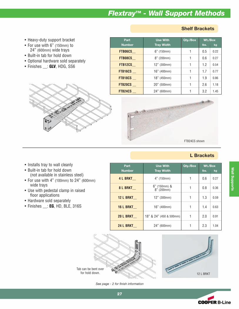
Shelf Brackets
L Brackets
Part Use With Qty./Box Wt./Box
Number Tray Width lbs. kg
FTB06CS__ 6” (150mm) 1 0.5 0.22
FTB08CS__ 8” (200mm) 1 0.6 0.27
FTB12CS__ 12” (300mm) 1 1.2 0.54
FTB16CS __ 16” (400mm) 1 1.7 0.77
FTB18CS __ 18” (450mm) 1 1.9 0.86
FTB20CS __ 20” (500mm) 1 2.6 1.18
FTB24CS __ 24” (600mm) 1 3.2 1.45
• Heavy-duty support bracket• For use with 6” (150mm) to
24” (600mm) wide trays• Built-in tab for hold down• Optional hardware sold separately• Finishes __: GLV, HDG, SS6
See page - 2 for finish information
FTB24CS shown
• Installs tray to wall cleanly• Built-in tab for hold down
(not available in stainless steel) • For use with 4” (100mm) to 24” (600mm)
wide trays• Use with pedestal clamp in raised
floor applications• Hardware sold separately• Finishes __: EG, HD, BLE, 316S
Part Use With Qty./Box Wt./Box
Number Tray Width lbs. kg
4 L BRKT__ 4” (150mm) 1 0.6 0.27
8 L BRKT__ 6” (150mm) & 1 0.8 0.368” (200mm)
12 L BRKT__ 12” (300mm) 1 1.3 0.59
16 L BRKT__ 16” (400mm) 1 1.4 0.63
20 L BRKT__ 18” & 24” (450 & 500mm) 1 2.0 0.91
24 L BRKT__ 24” (600mm) 1 2.3 1.04
12 L BRKT
Tab can be bent overfor hold down.
27
Flextray™ - Wall Support Methods
Wal
l Sup
po
rts
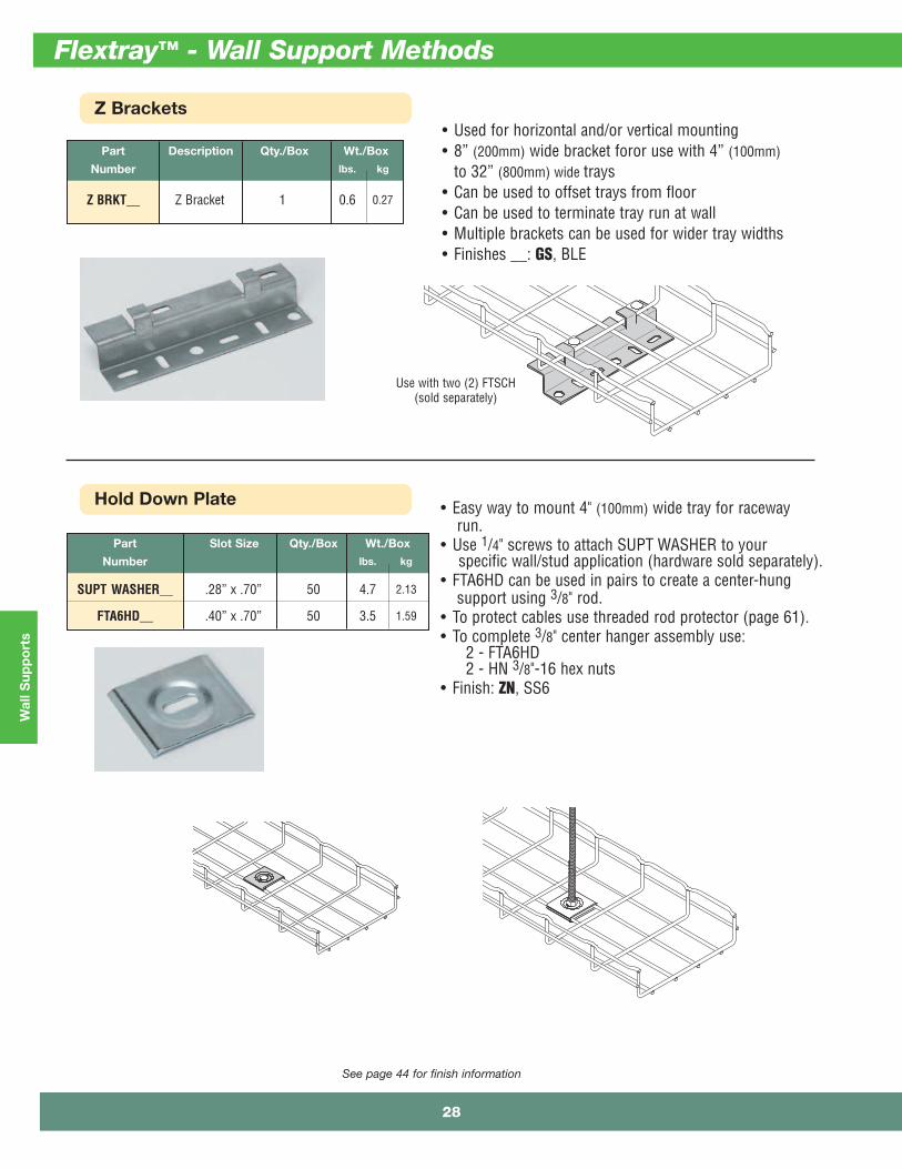
Z Brackets
See page 44 for finish information
Part Description Qty./Box Wt./Box
Number lbs. kg
Z BRKT__ Z Bracket 1 0.6 0.27
• Used for horizontal and/or vertical mounting• 8” (200mm) wide bracket foror use with 4” (100mm)
to 32” (800mm) wide trays• Can be used to offset trays from floor• Can be used to terminate tray run at wall• Multiple brackets can be used for wider tray widths• Finishes __: GS, BLE
Use with two (2) FTSCH(sold separately)
Hold Down Plate
Part Slot Size Qty./Box Wt./Box
Number lbs. kg
SUPT WASHER__ .28” x .70” 50 4.7 2.13
FTA6HD__ .40” x .70” 50 3.5 1.59
• Easy way to mount 4" (100mm) wide tray for racewayrun.
• Use 1/4" screws to attach SUPT WASHER to yourspecific wall/stud application (hardware sold separately).
• FTA6HD can be used in pairs to create a center-hungsupport using 3/8" rod.
• To protect cables use threaded rod protector (page 61).• To complete 3/8" center hanger assembly use:
2 - FTA6HD2 - HN 3/8"-16 hex nuts
• Finish: ZN, SS6
Flextray™ - Wall Support Methods
28

Wall S
upp
orts
Wall Supports
See page - 2 for finish information
Attachment Clips
Part Description Qty./Box Wt./Box
Number lbs. kg
ATTACHMENT CLP__ Attachment Clip 50 3.4 1.54Support for FT2x2x10
• Wall attachment for 2” (50mm) widetray only (FT2X2X10)
• Low-profile appearance• Built-in tab to hold down tray• Can also be used with 2” (50mm) Center
Hanger (see page 60)• Hardware sold separately• Finishes __: GS, BLE
Part Description Qty./Box Wt./Box
Number lbs. kg
Wall SupportFTA050CC__ Bracket 1 0.8 0.36
• Use to attach 2” (50mm) or 4” (100mm) traysto walls, struts or cabinets
• Use for raceway mounting• Mount to metal framing for vertical support• Tabs are built in for tray hold down• Mount to side rail for electrical box connection• Finishes __: GLV
Mounting Bracket
Part Description Qty./Box Wt./Box
Number lbs. kg
Light DutyFTB2UB__ Wall/Rack Bracket 10 2.1 0.95
• Designed to support FT2X2X10 Flextray• Click tabs for Flextray attachment• Use 1/4” hardware and washer (not included) to
mount bracket• Finishes __: SS6
.26" typ.(6.6 mm)
1" typ.(25 mm)
29
Flextray™ - Wall Support Methods

Wal
l Sup
po
rts
Wall Termination Kit
Part Length Qty./Box Wt./Box
Number lbs. kg
FTA9WTK__ 9” 1 1.3 0.59
• Kit includes all hardware necessary to supportFlextray when terminated at a wall
• Mount slotted angle to wall with up to 3/8"hardware (not included)
• Finishes __: ZN, FB, SS6
See page - 2 for finish information
Vertically MountedHorizontally Mounted
Wall Termination Kit includes:
1 - Angle with Slots2 - FTSCH
Wall Mount Kit
Part Length Qty./Box Wt./Box
Number lbs. kg
WB48WMK__ 8” 1 0.76 0.35
WB1224WMK__ 12” 1 1.22 0.55
• Kit includes all components necessary to mountFlextray to a wall horizontally or vertically
• Mount strut to wall with up to 1/2" hardware(not included)
• Finish: Channel - GLVHardware - ZNAvailable in SS6
Wall Mount Kit includes:
WB48WMK WB1224WMK1 1 B54SH Strut1 2 SUPT WASHER Hold Downs1 2 1/4"-20 x 1" Slotted Head Screw1 2 N224WO Channel Nut
WB1224WMK shown
Flextray™ - Wall Support Methods
30

Wall S
upp
orts
C Brackets
Part Description Qty./Box Wt./Box
Number lbs. kg
4 C BRKT__ 4” (100mm) C Bracket 1 1.2 0.54
8 C BRKT__ 8” (200mm) C Bracket 1 1.4 0.63
12 C BRKT__ 12” (300mm) C Bracket 1 1.9 0.86
• Tab can be used for hold down(stainless steel will not have these tabs)
• For use with 4” (100mm) to 12” (300mm) wide trays• C Bracket attaches to hard ceiling types• All brackets are 77/8” (200mm) tall• Cables can be side loaded• L Brackets (page 27) and C Brackets can be
combined for layered tray runs• Finishes __: EG, BLE, HD
See page - 2 for finish information
Hold down tab.
Assemble withSUPT WASHER &
FTHDWE 1/4.
31
Flextray™ - Wall Support Methods
F.A
.S.T
. Sys
tem
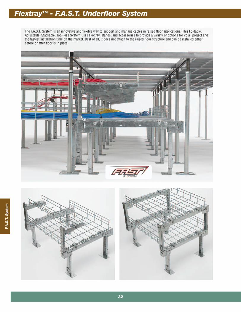
The F.A.S.T. System is an innovative and flexible way to support and manage cables in raised floor applications. This Foldable,Adjustable, Stackable, Tool-less System uses Flextray, stands, and accessories to provide a variety of options for your project andthe fastest installation time on the market. Best of all, it does not attach to the raised floor structure and can be installed eitherbefore or after floor is in place.
Flextray™ - F.A.S.T. Underfloor System
32

F.A.S
.T. System
See page - 2 for finish information
6” (150 mm)
2” deep 4” deep 6” deep
12” (300 mm)
20” (500 mm)
Widths
Depths
LD H
Part Width Length LD H Wt. Per Pc.Number in. mm in. mm in. mm in. mm lbs. kg
FTU2X6X2 6 150 23.9 603 1.63 41 2.02 51 2.03 0.92FTU2X6X4 6 150 47.5 1206 1.63 41 2.02 51 3.95 1.79FTU2X6X10 6 150 118.4 3008 1.63 41 2.02 51 9.72 4.41FTU2X12X2 12 300 23.9 603 1.63 41 2.02 51 2.99 1.36FTU2X12X4 12 300 47.5 1206 1.63 41 2.02 51 5.82 2.64FTU2X12X10 12 300 118.4 3008 1.63 41 2.02 51 14.32 6.50FTU2X20X2 20 500 23.9 603 1.63 41 2.02 51 4.28 1.94FTU2X20X4 20 500 47.5 1206 1.63 41 2.02 51 8.33 3.78FTU2X20X10 20 500 118.4 3008 1.63 41 2.02 51 20.45 9.28
FTU4X6X2 6 150 23.9 603 4.38 111 4.77 121 2.67 1.21FTU4X6X4 6 150 47.5 1206 4.38 111 4.77 121 5.20 2.36FTU4X6X10 6 150 118.4 3008 4.38 111 4.77 121 12.79 5.80FTU4X12X2 12 300 23.9 603 4.38 111 4.77 121 3.64 1.65FTU4X12X4 12 300 47.5 1206 4.38 111 4.77 121 7.08 3.21FTU4X12X10 12 300 118.4 3008 4.38 111 4.77 121 17.39 7.89FTU4X20X2 20 500 23.9 603 4.38 111 4.77 121 4.93 2.24FTU4X20X4 20 500 47.5 1206 4.38 111 4.77 121 9.58 4.35FTU4X20X10 20 500 118.4 3008 4.38 111 4.77 121 23.52 10.67
FTU6X6X2 6 150 23.9 603 6.38 162 6.77 172 3.32 1.51FTU6X6X4 6 150 47.5 1206 6.38 162 6.77 172 6.45 2.93FTU6X6X10 6 150 118.4 3008 6.38 162 6.77 172 15.85 7.19FTU6X12X2 12 300 23.9 603 6.38 162 6.77 172 4.28 1.94FTU6X12X4 12 300 47.5 1206 6.38 162 6.77 172 8.33 3.78FTU6X12X10 12 300 118.4 3008 6.38 162 6.77 172 20.45 9.28FTU6X20X2 20 500 23.9 603 6.38 162 6.77 172 5.57 2.53FTU6X20X4 20 500 47.5 1206 6.38 162 6.77 172 10.83 4.91FTU6X20X10 20 500 118.4 3008 6.38 162 6.77 172 26.59 12.06
WBUFLT 20 500 24 604 - - - - 2.96 1.34WBUFLT-12 12 250 24 604 - - - - 1.50 0.68WBUFLT-06 6 150 24 604 - - - - 1.00 0.45
LD HLD H
2” (5
0mm
)de
ep4”
(100
mm
)de
ep6”
(150
mm
)de
epFl
ats
Flat Fitting
• Rounded ends on all wires • UL Classified (see technical data for details)• Depths: 2”, 4”, & 6” nominal • Lengths: 24”, 48”, & 118”• Use flat fitting (WBUFLT) for turns• Wire Diameter: 0.191” (4.9mm)
• Standard finishes: GLVConsult customer service for otheravailable finishes
F.A.S.T. System Flextray
33
Flextray™ - F.A.S.T. Underfloor System

F.A
.S.T
. Sys
tem
See page - 2 for finish information
Part Max. Basket Width Height Adjustment Stands Wt. Per BoxNumber in. mm in. mm Per Box lbs. kg
FTU120404 12 300 4 101 2 1.82 0.82
FTU120608 12 300 6-8 152-203 2 2.79 1.26
WBU1216 12 300 10-16 254-406 2 7.44 3.37
WBU1224 * 12 300 18-24 457-609 2 9.06 4.11
WBU1231 * 12 300 25-31 635-787 2 10.52 4.77
FTU200404 20 500 4 101 2 2.34 1.06
FTU200608 20 500 6-8 152-203 2 3.36 1.52
WBU2016 20 500 10-16 254-406 2 8.56 3.88
WBU2024 20 500 18-24 457-609 2 10.20 4.62
WBU2031 * 20 500 25-31 635-787 2 11.64 5.28
WBU2016
WBU2016 shown
WBU1216
FTU200608
FTU200404
FTU120404
* Legs are packed separately in box and not inserted in stand.
WBU2016 stands shown in double tier application.Feet and adhesive pads not required for second tier assembly.
HeightAdjustment
Max. BasketWidth
• No tools required for installation • Formed top surface free of protrusions or
sharp edges • Up to 6” height adjustment • Inside and outside leg positioning• Folded and boxed for ease in shipping• Patent Pending• Stand part number includes:
one (1) standtwo (2) feettwo (2) adhesive padstwo (2) hold down clips
• Standard finish: Pre-Galvanized
Stands
Flextray™ - F.A.S.T. Underfloor System
34
F.A.S
.T. System
See page - 2 for finish information
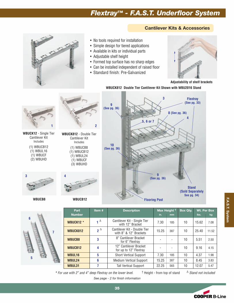
WBUCK12 - Single TierCantilever Kit
Includes
(1) WBUCB12(1) WBUL16(1) WBUCF(2) WBUHD
WBUCB8 WBUCB12
WBUCK812 - Double TierCantilever Kit
Includes
(1) WBUCB8(1) WBUCB12(1) WBUL24(1) WBUCF(3) WBUHD
Part Item # Description Max Height † Box Qty. Wt. Per BoxNumber in. mm lbs. kg
WBUCK12 * 1 ∆ Cantilever Kit - Single Tier 7.30 185 10 15.62 7.08with 12” Bracket
WBUCK812 2 ∆ Cantilever Kit - Double Tier 15.25 387 10 25.40 11.52with 8” & 12” Brackets
WBUCB8 3 8” Cantilever Bracket - - 10 5.51 2.50for 6” Flextray
WBUCB12 4 12” Cantilever Bracket - - 10 9.16 4.15for up to 12” Flextray
WBUL16 5 Short Vertical Support 7.30 185 10 4.37 1.98
WBUL24 6 Medium Vertical Support 15.25 387 10 8.45 3.83
WBUL31 7 Tall Vertical Support 22.25 565 10 12.07 5.47
* For use with 2” and 4” deep Flextray on the lower level. † Height - from top of stand ∆ Stand not included
1
WBUCK812 Double Tier Cantilever Kit Shown with WBU2016 Stand
Flextray (See pg. 33)
Adjustability of shelf brackets
Stand(Sold Separately
See pg. 34)Flooring Post
2
3 4
3
4
5
7
5, 6 or 7
8 (See pg. 36)
10(See pg. 36)
9(See pg. 36)
6
9(See pg. 36)
• No tools required for installation • Simple design for tiered applications • Available in kits or individual parts• Adjustable shelf height• Formed top surface has no sharp edges • Can be installed independent of raised floor • Standard finish: Pre-Galvanized
Cantilever Kits & Accessories
35
Flextray™ - F.A.S.T. Underfloor System
F.A
.S.T
. Sys
tem
See page - 2 for finish information
Part Overall Height Wt. Per EachNumber in. mm lbs. kg
WBU1203 3 76 1.32 0.60WBU1204 4 101 1.60 0.72WBU1205 5 127 1.88 0.85WBU1206 6 152 2.17 0.98
Part Item # Description Box Qty. Wt. Per BoxNumber lbs. kg
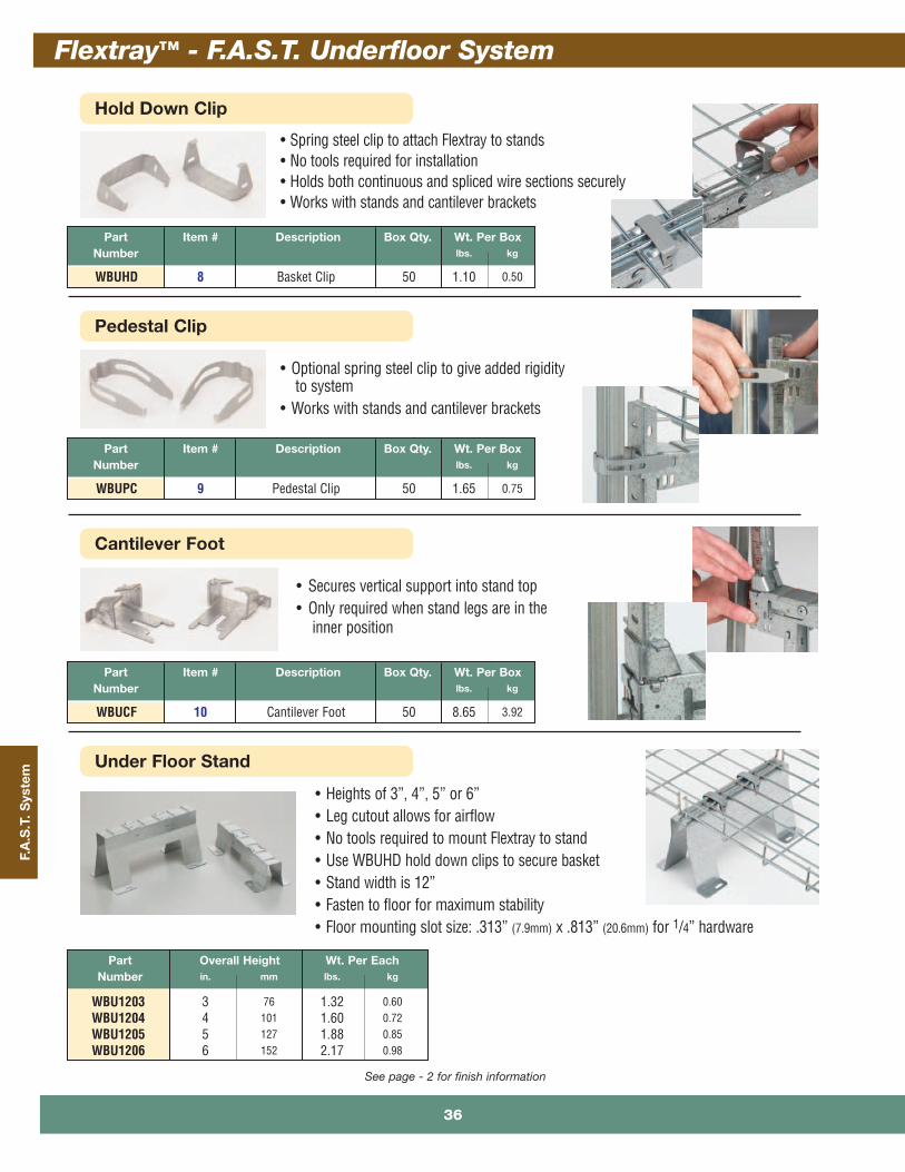
WBUHD 8 Basket Clip 50 1.10 0.50
Part Item # Description Box Qty. Wt. Per BoxNumber lbs. kg
WBUPC 9 Pedestal Clip 50 1.65 0.75
Part Item # Description Box Qty. Wt. Per BoxNumber lbs. kg
WBUCF 10 Cantilever Foot 50 8.65 3.92
• Heights of 3”, 4”, 5” or 6”• Leg cutout allows for airflow• No tools required to mount Flextray to stand• Use WBUHD hold down clips to secure basket• Stand width is 12” • Fasten to floor for maximum stability• Floor mounting slot size: .313” (7.9mm) x .813” (20.6mm) for 1/4” hardware
• Secures vertical support into stand top• Only required when stand legs are in the
inner position
• Optional spring steel clip to give added rigidityto system
• Works with stands and cantilever brackets
• Spring steel clip to attach Flextray to stands• No tools required for installation• Holds both continuous and spliced wire sections securely • Works with stands and cantilever brackets
Hold Down Clip
Pedestal Clip
Cantilever Foot
Under Floor Stand
Flextray™ - F.A.S.T. Underfloor System
36
F.A.S
.T. System
See page - 2 for finish information
Part System Width Length Box Qty. Wt. Per BoxNumber in. mm in. mm lbs. kg
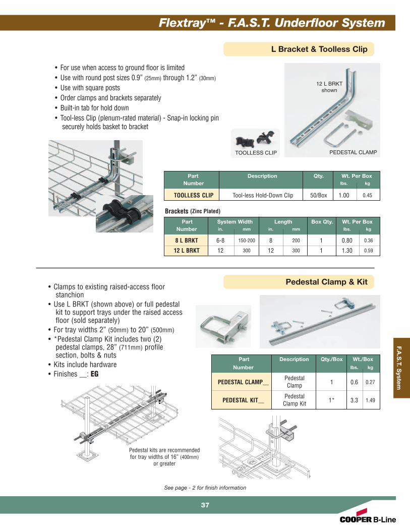
8 L BRKT 6-8 150-200 8 200 1 0.80 0.36
12 L BRKT 12 300 12 300 1 1.30 0.59
Part Description Qty. Wt. Per BoxNumber lbs. kg
TOOLLESS CLIP Tool-less Hold-Down Clip 50/Box 1.00 0.45
• For use when access to ground floor is limited• Use with round post sizes 0.9” (25mm) through 1.2” (30mm)
• Use with square posts• Order clamps and brackets separately• Built-in tab for hold down• Tool-less Clip (plenum-rated material) - Snap-in locking pin
securely holds basket to bracket
Brackets (Zinc Plated)
12 L BRKTshown
PEDESTAL CLAMPTOOLLESS CLIP
L Bracket & Toolless Clip
Pedestal Clamp & Kit
Part Description Qty./Box Wt./Box
Number lbs. kg
PedestalPEDESTAL CLAMP__ Clamp 1 0.6 0.27
PedestalPEDESTAL KIT__ Clamp Kit 1* 3.3 1.49
• Clamps to existing raised-access floorstanchion
• Use L BRKT (shown above) or full pedestalkit to support trays under the raised accessfloor (sold separately)
• For tray widths 2” (50mm) to 20” (500mm)• *Pedestal Clamp Kit includes two (2)
pedestal clamps, 28” (711mm) profilesection, bolts & nuts
• Kits include hardware• Finishes __: EG
Pedestal kits are recommendedfor tray widths of 16” (400mm)
or greater
37
Flextray™ - F.A.S.T. Underfloor System

F.A
.S.T
. Sys
tem
See page - 2 for finish information
• Under Floor Support Bracket provides rugged support forFlextray System from access floor post.
• To complete the installation, the following hardwaremust be ordered separately.(2) - B501 U-Bolts(1) - SUPT WASHER Hold Down(1) - 1/4"-20 x 1" Slotted Head Screw(1) - N224WO Channel Nut
• Finish: ZN
• Designed for attachment of Under Floor Support Brackets toaccess floor post. Each U-Bolt includes two (2) hex nuts.
• Finish: ZN
Part ‘A’ Thread Box Wt. Per BoxNumber in. mm Size Quantity lbs. kg
B501-1 13/8” 30 5/16”-18 50 7.0 3.17
B501-11/2 2” 50 5/16”-18 50 8.0 3.63
B501-2 27/16” 62 3/8”-16 20 5.4 2.45
B501-21/2 215/16” 75 3/8”-16 25 8.0 3.63
‘A’
‘A’
Part ‘A’ Thread Box Wt. Per BoxNumber in. mm in. mm Quantity lbs. kg
B409UF-12 12” 300 12” 300 1 3.6 1.63
B409UF-18 18” 450 18” 450 1 4.5 2.04
B409UF-21 21” 533 21” 533 1 5.4 2.45
Under Floor Support Bracket
U-Bolts
Flextray™ - F.A.S.T. Underfloor System
38

F.A.S
.T. System
See page - 2 for finish information
Part Description Box Qty. Wt. Per BoxNumber lbs. kg
WBUF Stand Foot 10 2.36 1.07
WBUTAPE Double-Sided Tape 50 2.50 1.13
WBUFA Floor Adhesive 1 Gallon 10.78 4.89
WBUFWBUTAPE
WBUFA
• WBUTAPE - Double-sided adhesive padsfor temporary positioning of floor standsPad Size: 2” (50mm) x 4” (100mm)
• WBUFA - Adhesive to secure stand to floor
Ground Bolt
Adhesive & Feet
Part Description Qty./Box Wt./Box
Number lbs. kg
GROUND BOLT Ground Bolt 1 0.11 0.05
• Attaches up to #1 ground wire to each traysection when separate ground wire is required
• Used for UL grounding compliance. • When using color powder coated finish or
paint, coating must be removed at the pointsof contact.
• Finish: Copper Plated
Floor Stand
• Non-metallic snap lock floor stand isdesigned for use under access floors.
• Floor stand elevates Flextray System15/8" (41.3mm) above the floor.
• To attach floor stand, use Liquid Nails™or anchors.
• Elevation increments of 13/8" (35mm)can be obtained by stacking floorstands.
• Sized for 1/4" hardware(order separately).
• Material: Black Plenum-rated PlasticPart Wt. Per Pc. Box
Number lbs. kg Quantity
FTA2FS 0.44 0.20 10
39
Flextray™ - F.A.S.T. Underfloor System
Acc
esso
ries
Flextray™ - Accessories
40

Accesso
ries
Covers
Dividers
Part Use With Qty./Box Wt./Box
Number Tray Width lbs. kg
2 IN COVER__ 2” (50mm) 1 3.8 1.72
4 IN COVER__ 4” (100mm) 1 5.7 2.58
6 IN COVER__ 6” (150mm) 1 6.7 3.04
8 IN COVER__ 8” (200mm) 1 8.7 3.94
12 IN COVER__ 12” (300mm) 1 11.6 5.26
16 IN COVER__ 16” (400mm) 1 15.6 7.07
18 IN COVER__ 18” (450mm) 1 17.0 7.71
20 IN COVER__ 20” (500mm) 1 18.5 8.39
24 IN COVER__ 24” (600mm) 1 22.0 9.98
• Protects cable from debris and dust• Adds security to cable installation• Easy bend-over tabs secure cover to trays• Available for 2” (50mm) to 24” (600mm) wide
trays• Comes in 118” (2997mm) length• Finishes __: GS, BLE, 304S, 316S
See page - 2 for finish information
• Allows cable separation within a single tray• Hemmed/rounded edge provides cable
jacket safety• Hardware included• Field miter for bends and turns• Dual slots every 24” (609mm) for field cutting• Available in 2” (50mm), 4” (100mm) and
6” (150mm) heights• Comes in 118.125” (3000mm) length• Finishes __: GS, BLE, 304S, 316S
Part Use With Qty./Box Wt./Box
Number Tray Depth lbs. kg
2 IN DIVIDER__ 2” (50mm) Deep 1 3.5 1.59
4 IN DIVIDER __ 4” (100mm) Deep 1 9.6 4.35
6 IN DIVIDER __ 6” (150mm) Deep 1 14.5 6.58
2” 4”
6”
Dividers includehardware shown
below
41
Flextray™ - Accessories

Acc
esso
ries
Blind Ends
Solid Bottom Inserts• Continuous support for sensitive cables• Security of cable in high-traffic areas• Hardware included• Available for 2” (50mm) to 24” (600mm) wide
trays• Comes in 118” (2997mm) length• Finishes __: GS, BLE, 304S, 316S
See page - 2 for finish information
Attach withFTHDWE 1/4 &
Top Washer
Part Use With Qty./Box Wt./Box
Number Tray Width lbs. kg
INSERT 4X118__ 4” (100mm) 1 6.8 3.08
INSERT 6X118__ 6” (150mm) 1 9.8 4.44
INSERT 8X118__ 8” (200mm) 1 13.3 6.03
INSERT 12X118__ 12” (300mm) 1 21.6 9.80
INSERT 16X118__ 16” (400mm) 1 26.4 11.97
INSERT 18X118__ 18” (450mm) 1 32.4 14.69
INSERT 20X118__ 20” (500mm) 1 32.9 14.92
INSERT 24X118__ 24” (600mm) 1 39.3 17.82
‘A’
Height
• Forms a closure for a dead-end Flextray • Hardware included• Finish: GLV, SS6
(*) Insert: 2 = 2" (50 mm), 4 = 4" (100 mm) for height
(**) Insert: 2 = 2" (50 mm), 4 = 4" (100 mm),6 = 6" (150 mm) for height
Part ‘A’ Height BoxNumber in. mm in. mm Quantity
FT BE 2X2 2” 50 2” 50 1
FT BE (*)X4 4” 100 (*) (*) 1
FT BE (*)X6 6” 150 (*) (*) 1
FT BE (**)X8 8” 200 (*) (*) 1
FT BE (**)X12 12” 300 (**) (**) 1
FT BE (**)X16 16” 400 (**) (**) 1
FT BE (**)X18 18” 450 (**) (**) 1
FT BE (**)X20 20” 500 (**) (**) 1
FT BE (**)X24 24” 600 (**) (**) 1
Flextray™ - Accessories
42

Accesso
ries
Cable Roller
Toolless Clip
See page - 2 for finish information
Part Description Qty./Box Wt./Box
Number lbs. kg
CABLE ROLLER Cable Roller 1 1.0 0.45
• Protects and maintains recommended cable radiifor Cat 5, Cat 5E, Cat 6, Cat 6A, Fiber, etc.
• Height of roller can be adjusted to tray depth• Installs in seconds with no tools• Reduces cable installation time• Prevents migration of cables• For use with 4” (100mm) to 32” (800mm) tray widths• Finish: Cast Aluminum
Quick, snap-together design
Part Description Qty./Box Wt./Box
Number lbs. kg
TOOLLESS CLIP Toolless 50 1.0 0.45Hold-Down Clip
• Securely holds tray to support• Snap-in locking pin• No tools or fastening required• Fastest hold-down method available• For use with the following:
FTB__CS (see pg. 27)L BRKT (see pg. 27)C BRKT (see pg. 31)
• Finish: Plenum rated resin (black)
Strut Mounting Clip
Part Description Qty./Box Wt./Box
Number lbs. kg
BW4 Strut Mounting Clip 100 0.9 0.41
• Use to secure Flextray to horizontal strutsupport
• Designed for use as shown in drawing(no load rating)
• Finish: Black Zinc Phosphate
43
Flextray™ - Accessories

Acc
esso
ries
Cable Drop Out
Drop Out Fitting
Part Description Qty./Box Wt./Box
Number lbs. kg
FTA2DO Cable Drop Out 10 0.17 0.08
• Non-metallic 2" (50mm) radius Cable Drop-Outsnap locks into mesh bottom and protects cablesfrom sharp bend
• Material: Black Plenum-rated Plastic
See page - 2 for finish information
Part Description Qty./Box Wt./Box
Number lbs. kg
DROP OUT__ Drop Out Fitting 1 0.5 0.22
• Keeps cable radius secure at drop point• For use with 4” (100mm) to 32” (800mm) wide trays • Attaches to tray without hardware• Drop outs can be attached at bottom, side or
ends of tray• Hold down tabs on bottom of drop out to secure
tray (tabs not available on stainless steel drop out)• Finishes __: EG, BLE
Flextray™ - Accessories
44

Accesso
ries
Rack Clamp
Conduit Connector
See page - 2 for finish information
• Conduit connector is designed to connectconduit to the side or bottom of Flextray
• Conduit bushing will remain outside of trayto keep cable pathway clear
• Bend tabs to secure connector to tray• No hardware included• Finishes __: GLV
Part Description Qty./Box Wt./Box
Number lbs. kg
FTA050CC__ 1/2” (15mm) Conduit Clip 4 0.8 0.36
FTA075CC __ 3/4” (20mm) Conduit Clip 4 1.0 0.45
FTA100CC __ 1” (25mm) Conduit Clip 4 1.9 0.86
FTA125CC __ 11/4” (32mm) Conduit Clip 4 2.6 1.18
Part Description Qty./Box Wt./Box
Number lbs. kg
RACK CLAMP__ Rack Clamp 4 4.7 2.13
• Securely holds tray down to rack• Installs without drilling• Black-painted finish to match rack• Finish__: BLE
Adaptor Kit
Part Description Qty./Box Wt./Box
Number lbs. kg
SB2204__ Adaptor Kit 1 0.37 0.17
• Adaptor kit includes all hardware necessary toconnect Flextray system to top of relay rack atright angle or parallel position
• Finish__: YZN (Yellow Zinc Chromate)
Adaptor Kit includes:(1) - Mounting Plate(2) - 5/16"-18 x 2" “J”-Bolts(2) - HN 5/16"-18 Hex Nuts(2) - LW 5/16" Lock Washers
45
Flextray™ - Accessories
Acc
esso
ries
Rubber Cap
Radius Shield
See page - 2 for finish information
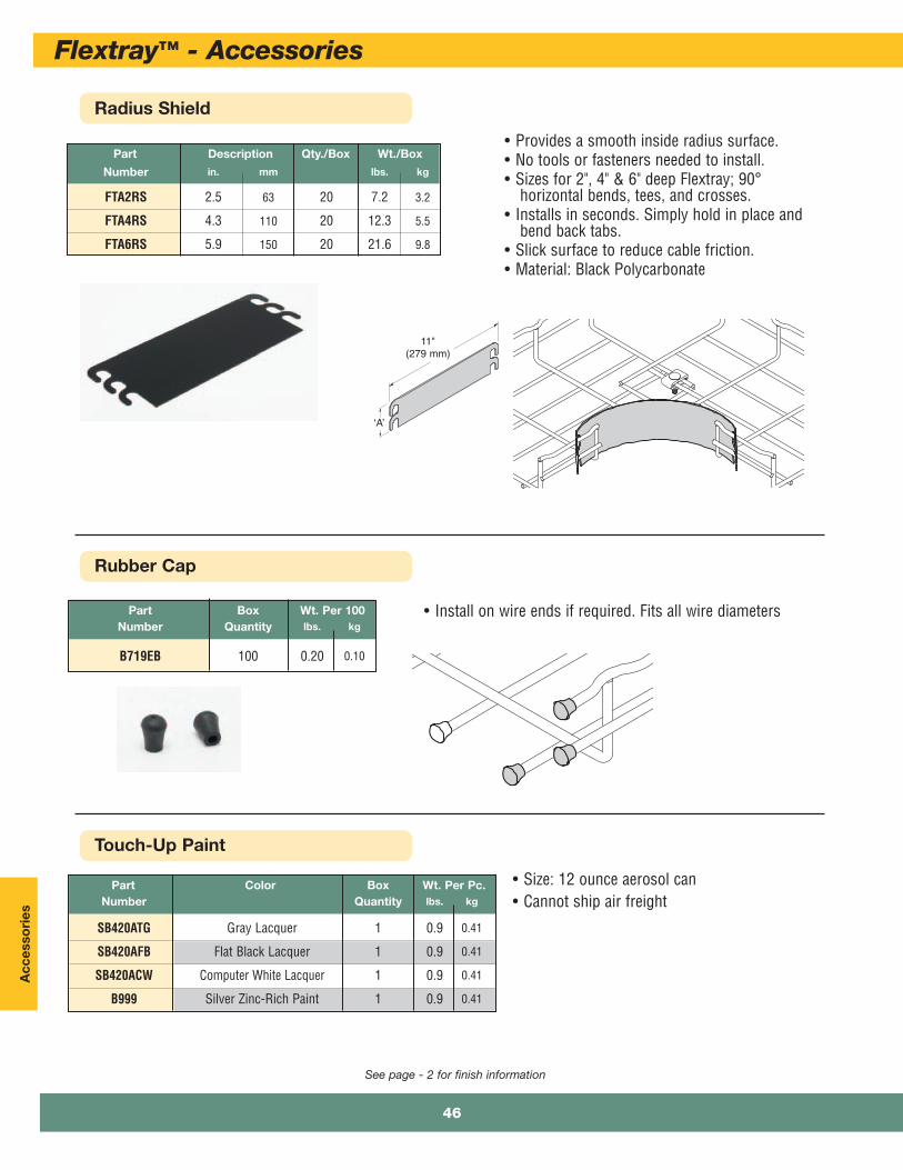
Part Description Qty./Box Wt./Box
Number in. mm lbs. kg
FTA2RS 2.5 63 20 7.2 3.2
FTA4RS 4.3 110 20 12.3 5.5
FTA6RS 5.9 150 20 21.6 9.8
• Provides a smooth inside radius surface.• No tools or fasteners needed to install.• Sizes for 2", 4" & 6" deep Flextray; 90°
horizontal bends, tees, and crosses.• Installs in seconds. Simply hold in place and
bend back tabs.• Slick surface to reduce cable friction. • Material: Black Polycarbonate
‘A’
11"(279 mm)
Part Color Box Wt. Per Pc.Number Quantity lbs. kg
SB420ATG Gray Lacquer 1 0.9 0.41
SB420AFB Flat Black Lacquer 1 0.9 0.41
SB420ACW Computer White Lacquer 1 0.9 0.41
B999 Silver Zinc-Rich Paint 1 0.9 0.41
• Install on wire ends if required. Fits all wire diametersPart Box Wt. Per 100Number Quantity lbs. kg
B719EB 100 0.20 0.10
Touch-Up Paint
• Size: 12 ounce aerosol can• Cannot ship air freight
Flextray™ - Accessories
46

Accesso
ries
Ground Bolt
Label Clip
Part Description Qty./Box Wt./Box
Number lbs. kg
LABEL CLIP 101/2” (267mm) Long 10 0.6 0.27
• Clips easily into trays• Use for identifying your cable pathways• Can be used on all tray sizes• Will not fit on side of 11/2” deep Flextray• Finish: Non-plenum-rated resins
Part Description Qty./Box Wt./Box
Number lbs. kg
GROUND BOLT Ground Bolt 1 0.11 0.05
• Attaches up to #1 ground wire to each traysection when separate ground wire is required
• Used for UL grounding compliance. • When using color powder coated finish or paint,
coating must be removed at the points ofcontact.
• Finish: Copper Plated
Ground Wire Supports
Part Description Qty./Box Wt./Box
Number lbs. kg
GROUND SUPT GL Ground Wire Support 100 0.6 0.27
• Supports ground wire along side of tray• Can be used on all trays• Finish __: Zinc Plated
See page - 2 for finish information
47
Flextray™ - Accessories
Acc
esso
ries
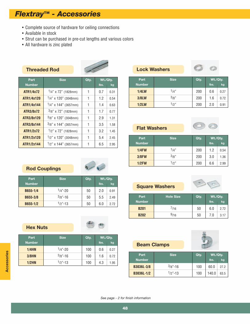
• Complete source of hardware for ceiling connections• Available in stock• Strut can be purchased in pre-cut lengths and various colors• All hardware is zinc plated
See page - 2 for finish information
Threaded Rod
Part Size Qty. Wt./Qty.
Number lbs. kg
ATR1/4x72 1/4” x 72” (1828mm) 1 0.7 0.31
ATR1/4x120 1/4” x 120” (3048mm) 1 1.2 0.54
ATR1/4x144 1/4” x 144” (3657mm) 1 1.4 0.63
ATR3/8x72 3/8” x 72” (1828mm) 1 1.7 0.77
ATR3/8x120 3/8” x 120” (3048mm) 1 2.9 1.31
ATR3/8x144 3/8” x 144” (3657mm) 1 3.5 1.58
ATR1/2x72 1/2” x 72” (1828mm) 1 3.2 1.45
ATR1/2x120 1/2” x 120” (3048mm) 1 5.4 2.45
ATR1/2x144 1/2” x 144” (3657mm) 1 6.5 2.95
Rod Couplings
Part Size Qty. Wt./Qty.
Number lbs. kg
B655-1/4 1/4”-20 50 2.0 0.91
B655-3/8 3/8”-16 50 5.5 2.49
B655-1/2 1/2”-13 50 6.0 2.72
Hex Nuts
Part Size Qty. Wt./Qty.
Number lbs. kg
1/4HN 1/4”-20 100 0.6 0.27
3/8HN 3/8”-16 100 1.6 0.72
1/2HN 1/2”-13 100 4.3 1.95
Lock Washers
Part Size Qty. Wt./Qty.
Number lbs. kg
1/4LW 1/4” 200 0.6 0.27
3/8LW 3/8” 200 1.6 0.72
1/2LW 1/2” 200 2.0 0.91
Flat Washers
Part Size Qty. Wt./Qty.
Number lbs. kg
1/4FW 1/4” 200 1.2 0.54
3/8FW 3/8” 200 3.0 1.36
1/2FW 1/2” 200 6.6 2.99
Square Washers
Part Hole Size Qty. Wt./Qty.
Number lbs. kg
B201 7/16 50 6.0 2.72
B202 9/16 50 7.0 3.17
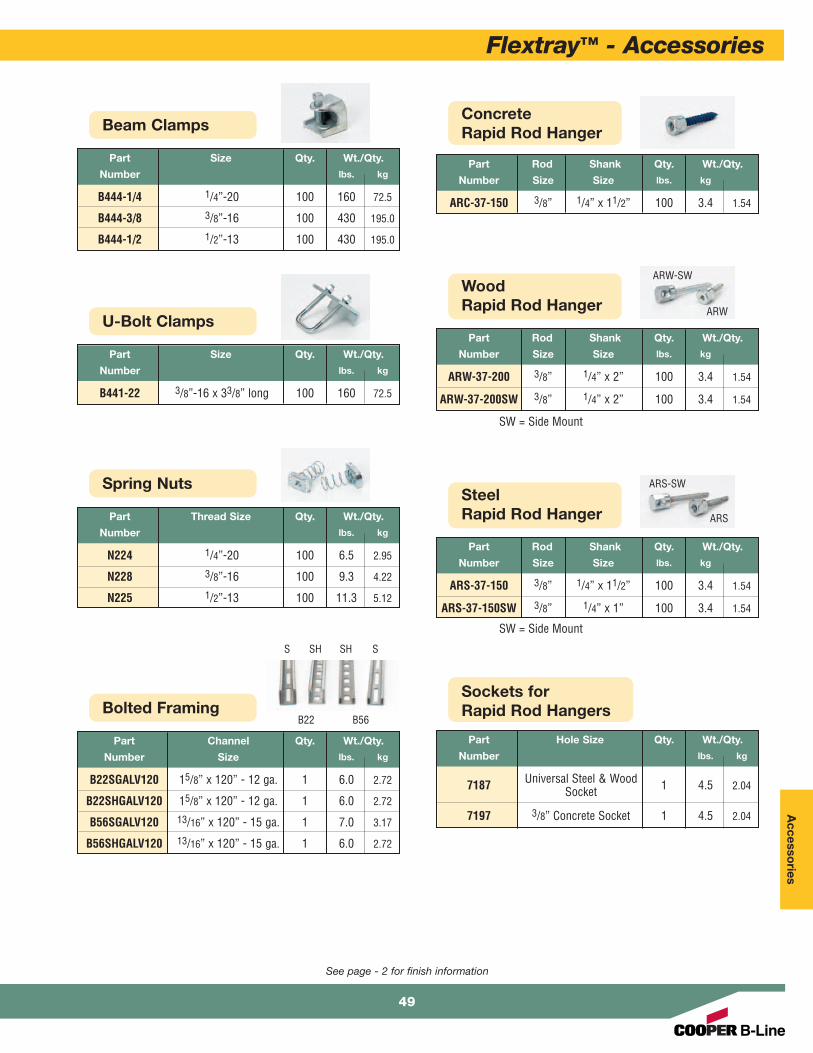
Beam Clamps
Part Size Qty. Wt./Qty.
Number lbs. kg
B3036L-3/8 3/8”-16 100 60.0 27.2
B3036L-1/2 1/2”-13 100 140.0 63.5
Flextray™ - Accessories
48
Accesso
ries
Spring Nuts
Part Thread Size Qty. Wt./Qty.
Number lbs. kg
N224 1/4”-20 100 6.5 2.95
N228 3/8”-16 100 9.3 4.22
N225 1/2”-13 100 11.3 5.12
Bolted Framing
Part Channel Qty. Wt./Qty.
Number Size lbs. kg
B22SGALV120 15/8” x 120” - 12 ga. 1 6.0 2.72
B22SHGALV120 15/8” x 120” - 12 ga. 1 6.0 2.72
B56SGALV120 13/16” x 120” - 15 ga. 1 7.0 3.17
B56SHGALV120 13/16” x 120” - 15 ga. 1 6.0 2.72
ConcreteRapid Rod Hanger
Part Rod Shank Qty. Wt./Qty.
Number Size Size lbs. kg
ARC-37-150 3/8” 1/4” x 11/2” 100 3.4 1.54
WoodRapid Rod Hanger
Part Rod Shank Qty. Wt./Qty.
Number Size Size lbs. kg
ARW-37-200 3/8” 1/4” x 2” 100 3.4 1.54
ARW-37-200SW 3/8” 1/4” x 2” 100 3.4 1.54
SteelRapid Rod Hanger
Part Rod Shank Qty. Wt./Qty.
Number Size Size lbs. kg
ARS-37-150 3/8” 1/4” x 11/2” 100 3.4 1.54
ARS-37-150SW 3/8” 1/4” x 1” 100 3.4 1.54
Sockets forRapid Rod Hangers
Part Hole Size Qty. Wt./Qty.
Number lbs. kg
7187 Universal Steel & Wood 1 4.5 2.04Socket
7197 3/8” Concrete Socket 1 4.5 2.04
Beam Clamps
Part Size Qty. Wt./Qty.
Number lbs. kg
B444-1/4 1/4”-20 100 160 72.5
B444-3/8 3/8”-16 100 430 195.0
B444-1/2 1/2”-13 100 430 195.0
U-Bolt Clamps
Part Size Qty. Wt./Qty.
Number lbs. kg
B441-22 3/8”-16 x 33/8” long 100 160 72.5
B22 B56
S SSH SH
ARW-SW
ARW
ARS-SW
ARS
SW = Side Mount
SW = Side Mount
49
See page - 2 for finish information
Flextray™ - Accessories

Inst
alla
tio
n
Flextray™ - Installation
50

Installation
51
Flextray™ - Installation
Flextray Cutters
Part Description Qty./Box Wt./Box
Number lbs. kg
CLEANSHEAR Cleanshear™1 4.3 1.95
Cutting Tool
• Exclusive, patented Cleanshear cuts tray fast• No sharp edges• Designed specifically for cutting Flextray• Safely cut and bend Flextray into any configuration
1 Face tray up. Slide cutter next to verticalwire and cut.
2 Turn tray to the side with open sidefacing you. Repeat step 1 to cut wire.
Patented
3 Finish cutting all side wires. 4 Turn tray open-side down and cut wiresfrom bottom of tray.
5 Finish cutting by moving to other sideof tray to cut remaining wires,

Inst
alla
tio
n
Flextray™ - Installation
52
Flextray Bender
Airshear Cutter
Part Description Qty./Box Wt./Box
Number lbs. kg
AIRSHEAR Pneumatic Cleanshear 1 9.0 4.08Cutting Tool
• Fastest wire mesh cutter available• 57% time savings over regular Cleanshear• Airshear is available when you have a large project
to install. Call us for details.
Part Description Qty./Box Wt./Box
Number lbs. kg
CLEANSHEAR BEND Cleanshear Cutting Tool 1 5.4 2.45With Bender Attachment
• Cleanshear™ Bender has our exclusivebending attachment
• Makes bending larger trays easy• Recommended for bending tray widths of
16” (400mm) or greater
Patented
Patented

Installation
53
Flextray™ - Installation
X
Completely adaptable, Cooper B-Line’s Flextray isdesigned to accommodate jobsite changes. Cut wireswith Cooper B-Line’s Angular Bolt Cutter, bend to createa bend, tee, or reducer.
For the best results, use a WB30BC Angular Blade OffsetBolt Cutter with 24" (600 mm) long handles. The OffsetBlade Cutter produces a clean cut. Position bolt cutterblades near the cross wire and perpendicular to wire tobe cut (see illustration above). Proper cut will make theassembly faster, easier and safer while minimizinggrinding.
Cut and remove each wire as illustrated below. Followcutting pattern and blade positioning. Placing Flextrayopen side down provides the optimum cutting angle.
Cutting Order
The Greenlee cable wire cutter makes flush cuts withoutburrs. Will cut .191" diameter wire in 2 seconds. Cutting headrotates 330° for ease of positioning and the tool automaticallyretracts when cut is complete.Comes with 2 batteries, charger, and carrying case.Approximately 250 cuts per charge.
WB30RB Replacement Blade
WB30BC Angular Bolt Cutter
® ¯
° ±
² ³
Offset Cut
Do not use centercut blades.
Part Length Wt. Per Cutter BoxNumber in. mm lbs. kg Quantity
WB50WC 123/4” 325 3.0 1.3 1
Part Number Description Box Quantity
WB50RB Replacement Blade 1
WB50BA Replacement Battery 1
Angular Bolt Cutter
Part Description Qty./Box Wt./Box
Number lbs. kg
WB30BC Bolt Cutter 1 6.8 3.1
WB30RB Replacement Blade 1 1.3 0.6

Inst
alla
tio
n
Flextray™ - Installation
54
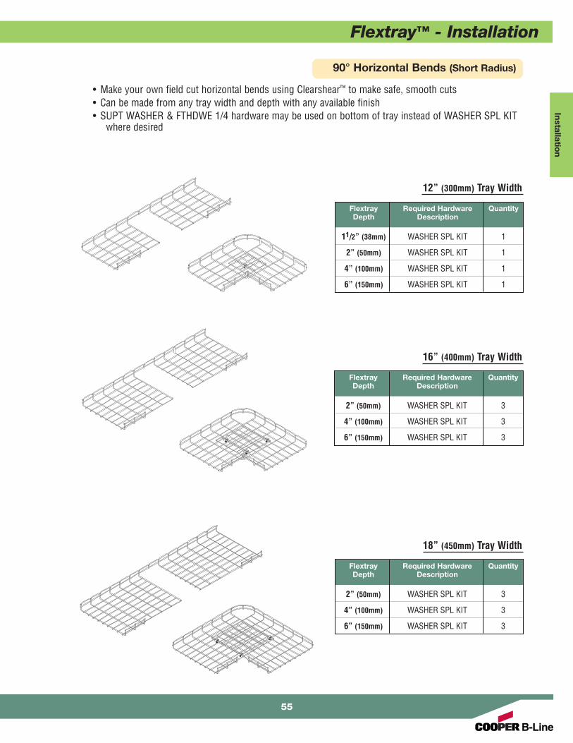
90° Horizontal Bends (Short Radius)
2” (50mm) Tray Width
• Make your own field cut horizontal bends using Clearshear™ to make safe, smooth cuts• Can be made from any tray width and depth with any available finish• SUPT WASHER & FTHDWE 1/4 hardware may be used on bottom of tray instead of WASHER SPL KIT
where desired
Flextray Required Hardware QuantityDepth Description
2” (50mm) WASHER SPL KIT 1
4” (100mm) Tray Width
Flextray Required Hardware QuantityDepth Description
11/2” (38mm) WASHER SPL KIT 1
2” (50mm) WASHER SPL KIT 1
4” (100mm) WASHER SPL KIT 1
6” (150mm) Tray Width
Flextray Required Hardware QuantityDepth Description
11/2” (38mm) WASHER SPL KIT 1
2” (50mm) WASHER SPL KIT 1
4” (100mm) WASHER SPL KIT 1
8” (200mm) Tray Width
Flextray Required Hardware QuantityDepth Description
11/2” (38mm) WASHER SPL KIT 1
2” (50mm) WASHER SPL KIT 1
4” (100mm) WASHER SPL KIT 1
6” (150mm) WASHER SPL KIT 1
Installation
Flextray™ - Installation
12” (300mm) Tray Width
Flextray Required Hardware QuantityDepth Description
11/2” (38mm) WASHER SPL KIT 1
2” (50mm) WASHER SPL KIT 1
4” (100mm) WASHER SPL KIT 1
6” (150mm) WASHER SPL KIT 1
90° Horizontal Bends (Short Radius)
• Make your own field cut horizontal bends using Clearshear™ to make safe, smooth cuts• Can be made from any tray width and depth with any available finish• SUPT WASHER & FTHDWE 1/4 hardware may be used on bottom of tray instead of WASHER SPL KIT
where desired
16” (400mm) Tray Width
Flextray Required Hardware QuantityDepth Description
2” (50mm) WASHER SPL KIT 3
4” (100mm) WASHER SPL KIT 3
6” (150mm) WASHER SPL KIT 3
18” (450mm) Tray Width
Flextray Required Hardware QuantityDepth Description
2” (50mm) WASHER SPL KIT 3
4” (100mm) WASHER SPL KIT 3
6” (150mm) WASHER SPL KIT 3
55

Inst
alla
tio
n
Flextray™ - Installation
56
90° Horizontal Bends (Short Radius)
• Make your own field cut horizontal bends using Clearshear™ to make safe, smooth cuts• Can be made from any tray width and depth with any available finish• SUPT WASHER & FTHDWE 1/4 hardware may be used on bottom of tray instead of WASHER SPL KIT
where desired
20” (500mm) Tray Width
Flextray Required Hardware QuantityDepth Description
2” (50mm) WASHER SPL KIT 3
4” (100mm) WASHER SPL KIT 3
6” (150mm) WASHER SPL KIT 3
24” (600mm) Tray Width
Flextray Required Hardware QuantityDepth Description
2” (50mm) WASHER SPL KIT 3
4” (100mm) WASHER SPL KIT 3
6” (150mm) WASHER SPL KIT 3

Installation
Flextray™ - Installation
90° Horizontal Bends (Long Radius)
90° Horizontal Bend From (2) Straight Sections
• Make your own field cut horizontal sweeps using Clearshear™ to make safe, smooth cuts• Can be made from any tray width and depth with any available finish• Cut as many Segments as required to control sweep radius (use chart for recommendations)• One (1) WASHER SPL KIT is required to connect each cut segment minus one, this segment
uses one (1) SPLICE BAR, two (2) FTHDWE 1/4 and two (2) BTM WASHER
Flextray Side Sections WASHER SPL KITWidth To Be Removed Qty.
4” (100mm) 1 2
6” (150mm) 2 2
8” (200mm) 2 2
12” (300mm) 3 2
16” (400mm) 4 3
18” (450mm) 5 3
20” (500mm) 5 3
24” (600mm) 6 4
30” (750mm) 8 4
32” (800mm) 8 4
• Cut required number of wire side sections listed inchart per the illustration below(Illustration is for a 8” (200mm) width)
• 1.5” deep Flextray has only one (1) side wire2” deep Flextray has two (2) side wires - shown4” deep Flextray has three (3) side wires6” deep Flextray has four (4) side wires
• Illustration shown below is for a 8” (200mm) width• 1.5” deep Flextray has only one (1) side wire
2” deep Flextray has two (2) side wires - shown4” deep Flextray has three (3) side wires6” deep Flextray has four (4) side wires
Component Qty.
Segments FTHDWE 1/4Flextray To Be WASHER & SPLICEWidth Removed SPL KIT BTM WASHER BAR
4” (100mm) 2 1 2 1
6” (150mm) 3 2 2 1
8” (200mm) 4 3 2 1
12” (300mm) 6 5 2 1
16” (400mm) 7 6 2 1
18” (450mm) 8 7 2 1
20” (500mm) 10 9 2 1
24” (600mm) 11 10 2 1
30” (750mm) 13 12 2 1
32” (800mm) 13 12 2 1
57
Inst
alla
tio
n
Flextray™ - Installation
58
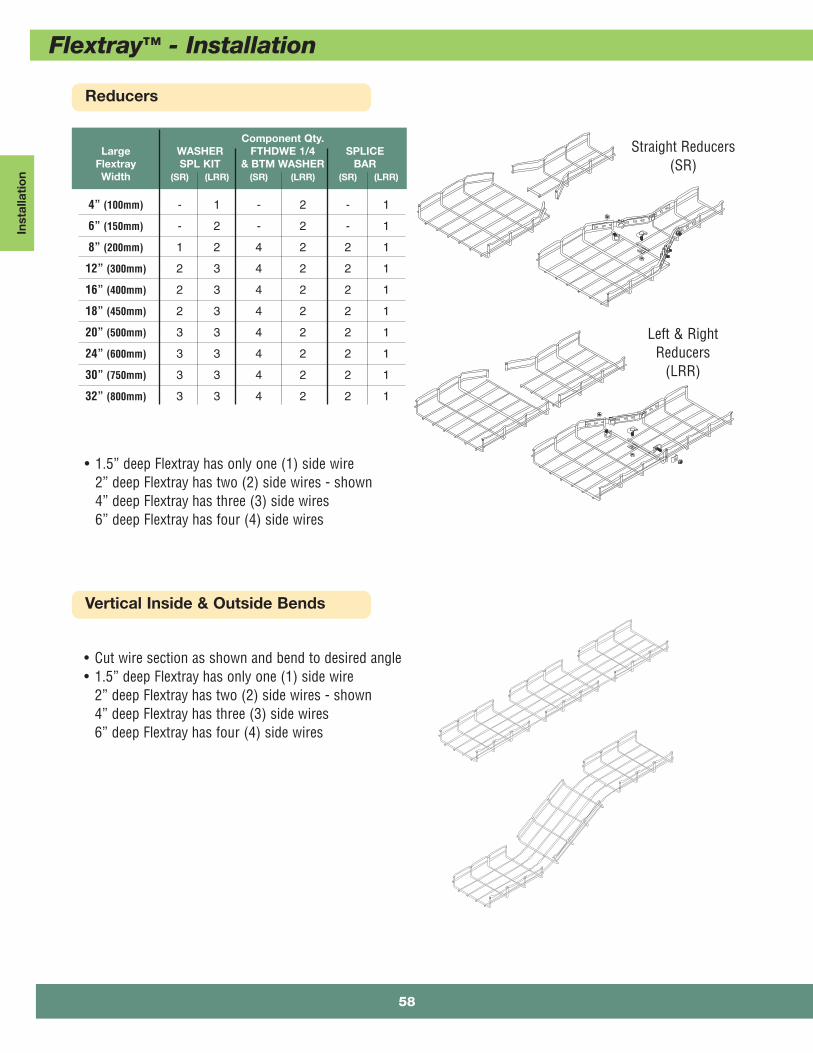
Reducers
Vertical Inside & Outside Bends
Component Qty.Large WASHER FTHDWE 1/4 SPLICE
Flextray SPL KIT & BTM WASHER BARWidth (SR) (LRR) (SR) (LRR) (SR) (LRR)
4” (100mm) - 1 - 2 - 1
6” (150mm) - 2 - 2 - 1
8” (200mm) 1 2 4 2 2 1
12” (300mm) 2 3 4 2 2 1
16” (400mm) 2 3 4 2 2 1
18” (450mm) 2 3 4 2 2 1
20” (500mm) 3 3 4 2 2 1
24” (600mm) 3 3 4 2 2 1
30” (750mm) 3 3 4 2 2 1
32” (800mm) 3 3 4 2 2 1
• 1.5” deep Flextray has only one (1) side wire2” deep Flextray has two (2) side wires - shown4” deep Flextray has three (3) side wires6” deep Flextray has four (4) side wires
Straight Reducers(SR)
Left & RightReducers
(LRR)
• Cut wire section as shown and bend to desired angle• 1.5” deep Flextray has only one (1) side wire
2” deep Flextray has two (2) side wires - shown4” deep Flextray has three (3) side wires6” deep Flextray has four (4) side wires
Installation
Flextray™ - Installation
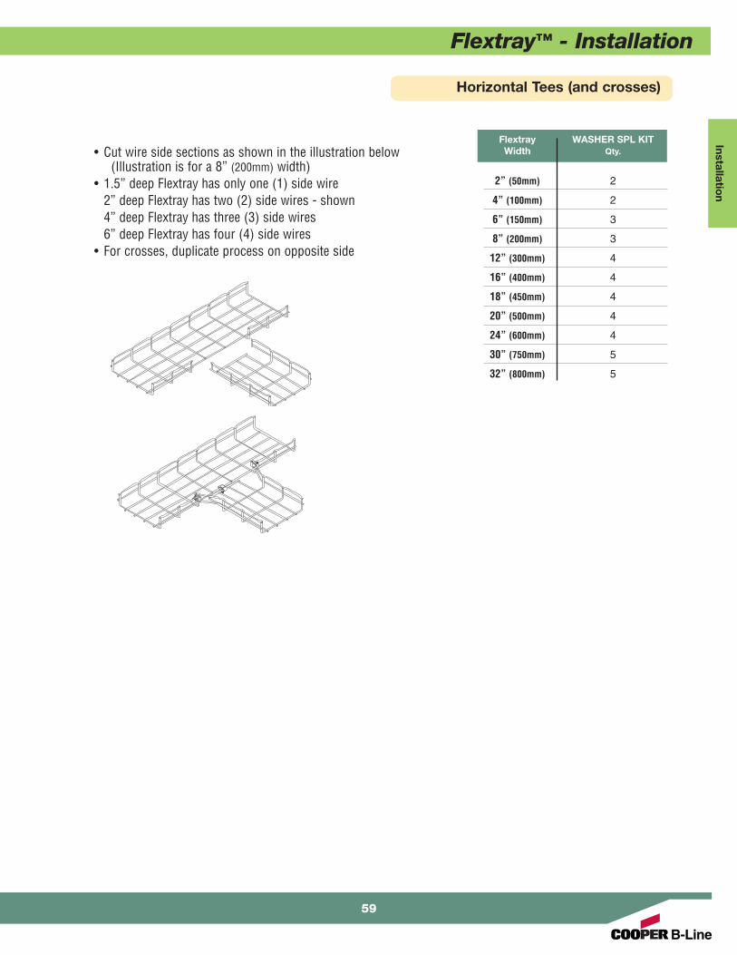
Horizontal Tees (and crosses)
Flextray WASHER SPL KITWidth Qty.
2” (50mm) 2
4” (100mm) 2
6” (150mm) 3
8” (200mm) 3
12” (300mm) 4
16” (400mm) 4
18” (450mm) 4
20” (500mm) 4
24” (600mm) 4
30” (750mm) 5
32” (800mm) 5
• Cut wire side sections as shown in the illustration below(Illustration is for a 8” (200mm) width)
• 1.5” deep Flextray has only one (1) side wire2” deep Flextray has two (2) side wires - shown4” deep Flextray has three (3) side wires6” deep Flextray has four (4) side wires
• For crosses, duplicate process on opposite side
59

Inst
alla
tio
n
Flextray™ - Installation
60
Recommended Support Locations For Fabricated Tray Fittings
The following are recommended support diagrams to serve as guidelines for installing wire basket cable support systems in the field.The information is intended to provide the installer some practical assistance when estimating the amounts of supports and to help inidentifying support locations for various field conditions for the installer. It does not, however, cover every situation that may arise wheninstalling the product. It may be possible to install narrow trays with lighter loads and fewer supports. Wider trays with heavier loading,trays with long radii, or those with multiple side wires cut may require additional support to avoid unwanted deflection.
2'-0'(610mm)
Horizontal Elbow SupportInside corner supports are not
required on 90°short radius bends.
2'-0'(610mm)
Horizontal Tee SupportOn 24" wide items, one supportmay be placed at the mid-pointof the back span as illustrated.
2'-0'(610mm)W
2'-0'(610mm)
Horizontal Wye SupportOn 24" wide items,
recommended distance is 1 ft. 6 in. (457mm) from splice
connection.
2'-0'(610mm)
SpliceJoint
2'-0'(610mm)
Horizontal Cross SupportOn 24" wide items, recommendeddistance is 1 ft. 6 in. (457mm) from
splice connection.
2'-0'(610mm)
2'-0'(610mm)
Straight Reducer SupportPlace reducer supports within
2 ft. (610mm)of each splice connection.
2'-0'(610mm)
SpliceJoint
2'-0'(610mm)
Left/Right Reducer SupportPlace reducer supports within
2 ft. (610mm)of each splice connection.
2'-0'(610mm)
Vertical ElbowsSupport vertical elbows at top
support location.Bend distances of 4 ft. (1219mm)and over should be supported at
each end as illustrated.
SpliceJoint
Bend Distance
TopSupport
Sp
ecification
Flextray™ - Specification
SECTION 16114 - WIRE BASKET CABLE SUPPORT SYSTEMPART 1 - GENERAL
1.01 DESCRIPTION
A. Work Included in This Section: Materials, equipment, fabrication, installation and tests in conformity with applicable codes and authorities havingjurisdiction for the following:
1. Wire mesh cable tray support systemsB. Related Work in Other Sections:
1. Conduit and wiring - BASIC MATERIALS AND METHODS Section.
1.02 INCORPORATED DOCUMENTS
A. Documents affecting work of this Section include, but are not limited to, Conditions of the Contract and Sections in Division 01 of these Specifications.B. Professionally recognized published specifications, standards, tests or recommended methods of trade, industry or governmental organizations apply
to work in this Section where cited below but not limited to:1. ANSI/NFPA 70 - National Electrical Code.2. ASTM B 633 - Specification for Electrodeposited Coatings of Zinc on Iron and Steel.3. ASTM A 653 - Specification for Steel Sheet, Zinc-Coated (Galvanized) by the Hot Dip Process.4. ASTM A 123 - Specification for Zinc (Hot Galvanized) Coatings on Iron and Steel.5. ASTM A 510 - Specification for General Requirements for Wire Rods and Coarse Round Wire, Carbon Steel.6. NEMA VE 1-2002 - Metal Cable Tray Systems.7. NEMA VE 2-2002 - Cable Tray Installation Guidelines.8. ASTM A 641 - Standard Specification for Zinc-Coated (Galvanized) Carbon Steel Wire9. ASTM A 580 - Standard Specification for Stainless Steel Wire
10. ASTM D 769 - Standard Specification for Black Oxide Coatings
1.03 QUALITY ASSURANCE
A. All equipment and accessories to be the product of a manufacturer regularly engaged in its manufacture.B. Supply all equipment and accessories new and free from defects.C. Supply all equipment and accessories in compliance with the applicable standards listed in Article 1.02 of this Section and with all applicable national,
state and local codes.D. All items of a given type shall be the products of the same manufacturer.E. NEC Compliance: Comply with NEC, as applicable to construction and installation of cable tray and cable channel systems (Article 318, NEC).F. NFPA Compliance Comply with NFPA 70B, “Recommended Practice for Electrical Equipment Maintenance” pertaining to installation of cable tray systems.
1.04 SUBMITTALS
A. Submittals shall be complete, bound under cover and indicating project title, specification section and/or drawings references. Contractor shallreview submittals for conformance with Contract Documents, make necessary revisions and submit to Architect, indicating the following:
1. Manufacturer's name, brand name and catalog sheet(s) reference of all equipment and materials specified under this Section.2. Submit drawings of wire mesh cable tray and accessories including connector assemblies, clamp assemblies, brackets, splice plates, splice bars,
grounding clamps and hold down plates showing accurately scaled components.3. Submit manufacturer's data on wire mesh cable tray support system including, but not limited to, types, materials, finishes and inside depths. 4. The drawings, which constitute a part of these specifications, indicate the general route of the wire mesh cable tray support systems. Data presented
on these drawings is as accurate as preliminary surveys and planning can determine until final equipment selection is made. Accuracy is not guaranteedand field verification of all dimensions, routing, etc., is required.
5. Specifications and drawings are for assistance and guidance, but exact routing, locations, distances and levels will be governed by actual field conditions. Contractor is directed to make field surveys as part of his work prior to submitting system layout drawings.
1.05 PRODUCT DELIVERY, STORAGE AND HANDLING
A. Ship equipment in its original packages to prevent damaging or entrance of foreign matter. All handling performed in accordance with manufacturer'srecommendations. Provide protective coverings during construction.
B. Replace at no expense to Owner, equipment or material damaged during storage or installation as directed by the Architect.C. Deliver wire mesh cable tray support systems and components carefully to avoid breakage, bending and scoring finishes. Do not install damaged
equipment.D. Store wire mesh cable tray and accessories in original cartons and in clean dry space; protect from weather and construction traffic.
61
Sp
ecifi
cati
on
Flextray™ - Specification
62
PART 2 - PRODUCTS
2.01 ACCEPTABLE MANUFACTURERS
A. Subject to compliance with these specifications, wire mesh cable tray support systems to be installed shall be as manufactured by Cooper B-Line, Inc.[or engineer-approved equal].
2.02 WIRE MESH CABLE TRAY SECTIONS AND COMPONENTS
A. Provide wire mesh cable tray of types and sizes indicated; with connector assemblies, clamp assemblies, connector plates, splice plates and splicebars. Construct units with rounded edges and smooth surfaces; in compliance with applicable standards; and with the following additional constructionfeatures.
B. Materials and Finishes: Material and finish specifications for [Carbon Steel Wire] [Pre-Galvanized Steel Wire][Stainless Steel Wire] are as follows:1. Electro-Plated Zinc Galvanizing: Straight sections shall be made from steel meeting the minimum mechanical properties of ASTM A 510,
Grade 1008 and shall be electro-plated zinc in accordance with ASTM B633, Type III, SC-1.2. Stainless Steel: Straight sections and accessories shall be made from AISI Type [304L][316L] Stainless Steel meeting the minimum mechanical
properties of ASTM A 580.3. Black Powder Coat: Straight sections shall be powder coated black with an average paint thickness of 1.2mils (30microns) to 3.0mils (75microns).4. Pre-Galvanized Zinc: Straight section shall be made from pre-galvanized steel meeting the minimum mechanical properties of ASTM A 641.5. Hot Dipped Galvanizing: Straight sections shall be made from steel meeting the minimum mechanical properties of ASTM A 510, Grade 1008
and shall be hot dipped galvanized after fabrication in accordance with ASTM A 123.6. Black Oxide: Certain support accessories and miscellaneous hardware shall be manufactured with a black oxide finish in accordance with
ASTM D 769.
2.03 TYPE OF WIRE MESH CABLE TRAY SUPPORT SYSTEM
A. All straight section longitudinal wires shall be constructed with a continuous top wire safety edge. Safety edge must be kinked and T-welded on all tray sizes.B. Wire mesh cable tray shall be made of high strength steel wires and formed into a standard 2 inch by 4 inch wire mesh pattern with intersecting wires
welded together. All mesh sections must have at least one bottom longitudinal wire along entire length of straight section. C. Wire mesh cable tray sizes shall conform to the following nominal criteria:
1. Straight sections shall be furnished in standard 118 inch lengths2. Wire diameter shall be 0.196” (5mm) minimum on all mesh sections (minimum size of 4.5mm on stainless steel)3. Wire mesh cable tray shall have a 1 inch usable loading depth by [4][6][8][12] inches wide.4. Wire mesh cable tray shall have a 2 inch usable loading depth by [2][4][6][8][12][16][18][20][24][30][32] inches wide.5. Wire mesh cable tray shall have a 4 inch usable loading depth by [4][6][8][12][16][18][20][24][30] inches wide.6. Wire mesh cable tray shall have a 6 inch usable loading depth by [8][12][16][18][20][24] inches wide.
D. All fittings shall be field formed, from straight sections, in accordance with manufacturer's instructions.E. In order for system to be approved as an Equipment Ground Conductor (EGC), all splicing assemblies shall be UL/CSA approved as an EGC.
When using powder coated wire mesh cable tray as an EGC, the paint must be completely removed at all contact points of splice/ground bolt attachment. F. Wire mesh cable tray supports shall be center support hangers, trapeze hangers or wall brackets as manufactured by Cooper B-Line, Inc. [or engineer
approved equal].G. Trapeze hangers or center support hangers shall be supported by 1/4 inch or 3/8 inch diameter rods.H. Special accessories shall be furnished as required to protect, support and install a wire mesh cable tray support system.
PART 3 - EXECUTION
3.01 INSTALLATION OF WIRE MESH CABLE TRAY
A. Install wire mesh cable tray as indicated; in accordance with recognized industry practices (NEMA VE-2 2000), to ensure that the cable tray equipmentcomplies with requirements of NEC, and applicable portions of NFPA 70B and NECA's “Standards of Installation” pertaining to general electricalinstallation practices.
B. Coordinate wire mesh cable tray with other electrical work as necessary to properly interface installation of wire mesh cable tray runway with other work.C. Provide sufficient space encompassing wire mesh cable tray to permit access for installing and maintaining cables.
END OF SECTION
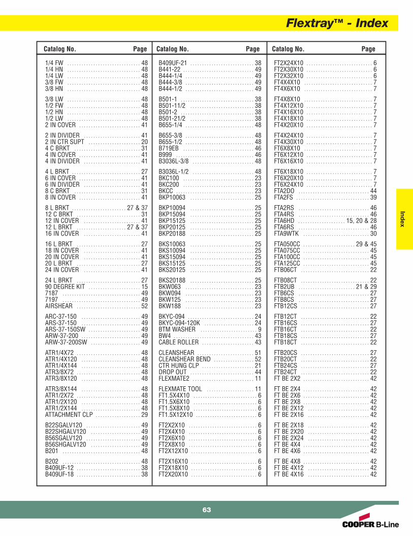
Flextray™ - IndexInd
ex
Catalog No. PageCatalog No. Page Catalog No. Page
1/4 FW . . . . . . . . . . . . . . . . . . . . . . . . . . . . . . . 481/4 HN . . . . . . . . . . . . . . . . . . . . . . . . . . . . . . . 481/4 LW . . . . . . . . . . . . . . . . . . . . . . . . . . . . . . . 483/8 FW . . . . . . . . . . . . . . . . . . . . . . . . . . . . . . . 483/8 HN . . . . . . . . . . . . . . . . . . . . . . . . . . . . . . . 48
3/8 LW . . . . . . . . . . . . . . . . . . . . . . . . . . . . . . . 481/2 FW . . . . . . . . . . . . . . . . . . . . . . . . . . . . . . . 481/2 HN . . . . . . . . . . . . . . . . . . . . . . . . . . . . . . . 481/2 LW . . . . . . . . . . . . . . . . . . . . . . . . . . . . . . . 482 IN COVER . . . . . . . . . . . . . . . . . . . . . . . . . . 41
2 IN DIVIDER . . . . . . . . . . . . . . . . . . . . . . . . 412 IN CTR SUPT . . . . . . . . . . . . . . . . . . . . . . 204 C BRKT . . . . . . . . . . . . . . . . . . . . . . . . . . . . 314 IN COVER . . . . . . . . . . . . . . . . . . . . . . . . . . 414 IN DIVIDER . . . . . . . . . . . . . . . . . . . . . . . . 41
4 L BRKT . . . . . . . . . . . . . . . . . . . . . . . . . . . . . 276 IN COVER . . . . . . . . . . . . . . . . . . . . . . . . . . 416 IN DIVIDER . . . . . . . . . . . . . . . . . . . . . . . . 418 C BRKT . . . . . . . . . . . . . . . . . . . . . . . . . . . . 318 IN COVER . . . . . . . . . . . . . . . . . . . . . . . . . . 41
8 L BRKT . . . . . . . . . . . . . . . . . . . . . . . 27 & 3712 C BRKT . . . . . . . . . . . . . . . . . . . . . . . . . . . 3112 IN COVER . . . . . . . . . . . . . . . . . . . . . . . . 4112 L BRKT . . . . . . . . . . . . . . . . . . . . . 27 & 3716 IN COVER . . . . . . . . . . . . . . . . . . . . . . . . 41
16 L BRKT . . . . . . . . . . . . . . . . . . . . . . . . . . . 2718 IN COVER . . . . . . . . . . . . . . . . . . . . . . . . 4120 IN COVER . . . . . . . . . . . . . . . . . . . . . . . . 4120 L BRKT . . . . . . . . . . . . . . . . . . . . . . . . . . . 2724 IN COVER . . . . . . . . . . . . . . . . . . . . . . . . 41
24 L BRKT . . . . . . . . . . . . . . . . . . . . . . . . . . . 2790 DEGREE KIT . . . . . . . . . . . . . . . . . . . . . . 157187 . . . . . . . . . . . . . . . . . . . . . . . . . . . . . . . . . 497197 . . . . . . . . . . . . . . . . . . . . . . . . . . . . . . . . . 49AIRSHEAR . . . . . . . . . . . . . . . . . . . . . . . . . . . 52
ARC-37-150 . . . . . . . . . . . . . . . . . . . . . . . . . 49ARS-37-150 . . . . . . . . . . . . . . . . . . . . . . . . . 49ARS-37-150SW . . . . . . . . . . . . . . . . . . . . . . 49ARW-37-200 . . . . . . . . . . . . . . . . . . . . . . . . . 49ARW-37-200SW . . . . . . . . . . . . . . . . . . . . . 49
ATR1/4X72 . . . . . . . . . . . . . . . . . . . . . . . . . . . 48ATR1/4X120 . . . . . . . . . . . . . . . . . . . . . . . . . 48ATR1/4X144 . . . . . . . . . . . . . . . . . . . . . . . . . 48ATR3/8X72 . . . . . . . . . . . . . . . . . . . . . . . . . . . 48ATR3/8X120 . . . . . . . . . . . . . . . . . . . . . . . . . 48
ATR3/8X144 . . . . . . . . . . . . . . . . . . . . . . . . . 48ATR1/2X72 . . . . . . . . . . . . . . . . . . . . . . . . . . . 48ATR1/2X120 . . . . . . . . . . . . . . . . . . . . . . . . . 48ATR1/2X144 . . . . . . . . . . . . . . . . . . . . . . . . . 48ATTACHMENT CLP . . . . . . . . . . . . . . . . . . . 29
B22SGALV120 . . . . . . . . . . . . . . . . . . . . . . . 49B22SHGALV120 . . . . . . . . . . . . . . . . . . . . . 49B56SGALV120 . . . . . . . . . . . . . . . . . . . . . . . 49B56SHGALV120 . . . . . . . . . . . . . . . . . . . . . 49B201 . . . . . . . . . . . . . . . . . . . . . . . . . . . . . . . . . 48
B202 . . . . . . . . . . . . . . . . . . . . . . . . . . . . . . . . . 48B409UF-12 . . . . . . . . . . . . . . . . . . . . . . . . . . . 38B409UF-18 . . . . . . . . . . . . . . . . . . . . . . . . . . . 38
B409UF-21 . . . . . . . . . . . . . . . . . . . . . . . . . . . 38B441-22 . . . . . . . . . . . . . . . . . . . . . . . . . . . . . . 49B444-1/4 . . . . . . . . . . . . . . . . . . . . . . . . . . . . . 49B444-3/8 . . . . . . . . . . . . . . . . . . . . . . . . . . . . . 49B444-1/2 . . . . . . . . . . . . . . . . . . . . . . . . . . . . . 49
B501-1 . . . . . . . . . . . . . . . . . . . . . . . . . . . . . . . 38B501-11/2 . . . . . . . . . . . . . . . . . . . . . . . . . . . 38B501-2 . . . . . . . . . . . . . . . . . . . . . . . . . . . . . . . 38B501-21/2 . . . . . . . . . . . . . . . . . . . . . . . . . . . 38B655-1/4 . . . . . . . . . . . . . . . . . . . . . . . . . . . . . 48
B655-3/8 . . . . . . . . . . . . . . . . . . . . . . . . . . . . . 48B655-1/2 . . . . . . . . . . . . . . . . . . . . . . . . . . . . . 48B719EB . . . . . . . . . . . . . . . . . . . . . . . . . . . . . . 46B999 . . . . . . . . . . . . . . . . . . . . . . . . . . . . . . . . . 46B3036L-3/8 . . . . . . . . . . . . . . . . . . . . . . . . . . 48
B3036L-1/2 . . . . . . . . . . . . . . . . . . . . . . . . . . 48BKC100 . . . . . . . . . . . . . . . . . . . . . . . . . . . . . . 23BKC200 . . . . . . . . . . . . . . . . . . . . . . . . . . . . . . 23BKCC . . . . . . . . . . . . . . . . . . . . . . . . . . . . . . . . . 23BKP10063 . . . . . . . . . . . . . . . . . . . . . . . . . . . 25
BKP10094 . . . . . . . . . . . . . . . . . . . . . . . . . . . 25BKP15094 . . . . . . . . . . . . . . . . . . . . . . . . . . . 25BKP15125 . . . . . . . . . . . . . . . . . . . . . . . . . . . 25BKP20125 . . . . . . . . . . . . . . . . . . . . . . . . . . . 25BKP20188 . . . . . . . . . . . . . . . . . . . . . . . . . . . 25
BKS10063 . . . . . . . . . . . . . . . . . . . . . . . . . . . 25BKS10094 . . . . . . . . . . . . . . . . . . . . . . . . . . . 25BKS15094 . . . . . . . . . . . . . . . . . . . . . . . . . . . 25BKS15125 . . . . . . . . . . . . . . . . . . . . . . . . . . . 25BKS20125 . . . . . . . . . . . . . . . . . . . . . . . . . . . 25
BKS20188 . . . . . . . . . . . . . . . . . . . . . . . . . . . 25BKW063 . . . . . . . . . . . . . . . . . . . . . . . . . . . . . 23BKW094 . . . . . . . . . . . . . . . . . . . . . . . . . . . . . 23BKW125 . . . . . . . . . . . . . . . . . . . . . . . . . . . . . 23BKW188 . . . . . . . . . . . . . . . . . . . . . . . . . . . . . 23
BKYC-094 . . . . . . . . . . . . . . . . . . . . . . . . . . . . 24BKYC-094-120K . . . . . . . . . . . . . . . . . . . . . 24BTM WASHER . . . . . . . . . . . . . . . . . . . . . . . . 9BW4 . . . . . . . . . . . . . . . . . . . . . . . . . . . . . . . . . . 43CABLE ROLLER . . . . . . . . . . . . . . . . . . . . . . 43
CLEANSHEAR . . . . . . . . . . . . . . . . . . . . . . . . 51CLEANSHEAR BEND . . . . . . . . . . . . . . . . . 52CTR HUNG CLP . . . . . . . . . . . . . . . . . . . . . . 21DROP OUT . . . . . . . . . . . . . . . . . . . . . . . . . . . 44FLEXMATE2 . . . . . . . . . . . . . . . . . . . . . . . . . . 11
FLEXMATE TOOL . . . . . . . . . . . . . . . . . . . . 11FT1.5X4X10 . . . . . . . . . . . . . . . . . . . . . . . . . . . 6FT1.5X6X10 . . . . . . . . . . . . . . . . . . . . . . . . . . . 6FT1.5X8X10 . . . . . . . . . . . . . . . . . . . . . . . . . . . 6FT1.5X12X10 . . . . . . . . . . . . . . . . . . . . . . . . . . 6
FT2X2X10 . . . . . . . . . . . . . . . . . . . . . . . . . . . . . 6FT2X4X10 . . . . . . . . . . . . . . . . . . . . . . . . . . . . . 6FT2X6X10 . . . . . . . . . . . . . . . . . . . . . . . . . . . . . 6FT2X8X10 . . . . . . . . . . . . . . . . . . . . . . . . . . . . . 6FT2X12X10 . . . . . . . . . . . . . . . . . . . . . . . . . . . . 6
FT2X16X10 . . . . . . . . . . . . . . . . . . . . . . . . . . . . 6FT2X18X10 . . . . . . . . . . . . . . . . . . . . . . . . . . . . 6FT2X20X10 . . . . . . . . . . . . . . . . . . . . . . . . . . . . 6
FT2X24X10 . . . . . . . . . . . . . . . . . . . . . . . . . . . . 6FT2X30X10 . . . . . . . . . . . . . . . . . . . . . . . . . . . . 6FT2X32X10 . . . . . . . . . . . . . . . . . . . . . . . . . . . . 6FT4X4X10 . . . . . . . . . . . . . . . . . . . . . . . . . . . . . 7FT4X6X10 . . . . . . . . . . . . . . . . . . . . . . . . . . . . . 7
FT4X8X10 . . . . . . . . . . . . . . . . . . . . . . . . . . . . . 7FT4X12X10 . . . . . . . . . . . . . . . . . . . . . . . . . . . . 7FT4X16X10 . . . . . . . . . . . . . . . . . . . . . . . . . . . . 7FT4X18X10 . . . . . . . . . . . . . . . . . . . . . . . . . . . . 7FT4X20X10 . . . . . . . . . . . . . . . . . . . . . . . . . . . . 7
FT4X24X10 . . . . . . . . . . . . . . . . . . . . . . . . . . . . 7FT4X30X10 . . . . . . . . . . . . . . . . . . . . . . . . . . . . 7FT6X8X10 . . . . . . . . . . . . . . . . . . . . . . . . . . . . . 7FT6X12X10 . . . . . . . . . . . . . . . . . . . . . . . . . . . . 7FT6X16X10 . . . . . . . . . . . . . . . . . . . . . . . . . . . . 7
FT6X18X10 . . . . . . . . . . . . . . . . . . . . . . . . . . . . 7FT6X20X10 . . . . . . . . . . . . . . . . . . . . . . . . . . . . 7FT6X24X10 . . . . . . . . . . . . . . . . . . . . . . . . . . . . 7FTA2DO . . . . . . . . . . . . . . . . . . . . . . . . . . . . . . 44FTA2FS . . . . . . . . . . . . . . . . . . . . . . . . . . . . . . . 39
FTA2RS . . . . . . . . . . . . . . . . . . . . . . . . . . . . . . 46FTA4RS . . . . . . . . . . . . . . . . . . . . . . . . . . . . . . 46FTA6HD . . . . . . . . . . . . . . . . . . . . 15, 20 & 28FTA6RS . . . . . . . . . . . . . . . . . . . . . . . . . . . . . . 46FTA9WTK . . . . . . . . . . . . . . . . . . . . . . . . . . . . 30
FTA050CC . . . . . . . . . . . . . . . . . . . . . . 29 & 45FTA075CC . . . . . . . . . . . . . . . . . . . . . . . . . . . . 45FTA100CC . . . . . . . . . . . . . . . . . . . . . . . . . . . . 45FTA125CC . . . . . . . . . . . . . . . . . . . . . . . . . . . . 45FTB06CT . . . . . . . . . . . . . . . . . . . . . . . . . . . . . 22
FTB08CT . . . . . . . . . . . . . . . . . . . . . . . . . . . . . 22FTB2UB . . . . . . . . . . . . . . . . . . . . . . . . 21 & 29FTB6CS . . . . . . . . . . . . . . . . . . . . . . . . . . . . . . 27FTB8CS . . . . . . . . . . . . . . . . . . . . . . . . . . . . . . 27FTB12CS . . . . . . . . . . . . . . . . . . . . . . . . . . . . . 27
FTB12CT . . . . . . . . . . . . . . . . . . . . . . . . . . . . . 22FTB16CS . . . . . . . . . . . . . . . . . . . . . . . . . . . . . 27FTB16CT . . . . . . . . . . . . . . . . . . . . . . . . . . . . . 22FTB18CS . . . . . . . . . . . . . . . . . . . . . . . . . . . . . 27FTB18CT . . . . . . . . . . . . . . . . . . . . . . . . . . . . . 22
FTB20CS . . . . . . . . . . . . . . . . . . . . . . . . . . . . . 27FTB20CT . . . . . . . . . . . . . . . . . . . . . . . . . . . . . 22FTB24CS . . . . . . . . . . . . . . . . . . . . . . . . . . . . . 27FTB24CT . . . . . . . . . . . . . . . . . . . . . . . . . . . . . 22FT BE 2X2 . . . . . . . . . . . . . . . . . . . . . . . . . . . . 42
FT BE 2X4 . . . . . . . . . . . . . . . . . . . . . . . . . . . . 42FT BE 2X6 . . . . . . . . . . . . . . . . . . . . . . . . . . . . 42FT BE 2X8 . . . . . . . . . . . . . . . . . . . . . . . . . . . . 42FT BE 2X12 . . . . . . . . . . . . . . . . . . . . . . . . . . 42FT BE 2X16 . . . . . . . . . . . . . . . . . . . . . . . . . . 42
FT BE 2X18 . . . . . . . . . . . . . . . . . . . . . . . . . . 42FT BE 2X20 . . . . . . . . . . . . . . . . . . . . . . . . . . 42FT BE 2X24 . . . . . . . . . . . . . . . . . . . . . . . . . . 42FT BE 4X4 . . . . . . . . . . . . . . . . . . . . . . . . . . . . 42FT BE 4X6 . . . . . . . . . . . . . . . . . . . . . . . . . . . . 42
FT BE 4X8 . . . . . . . . . . . . . . . . . . . . . . . . . . . . 42FT BE 4X12 . . . . . . . . . . . . . . . . . . . . . . . . . . 42FT BE 4X16 . . . . . . . . . . . . . . . . . . . . . . . . . . 42
63

Flextray™ - Index
64
Ind
ex
Catalog No. PageCatalog No. Page Catalog No. Page
FT BE 4X18 . . . . . . . . . . . . . . . . . . . . . . . . . . 42FT BE 4X20 . . . . . . . . . . . . . . . . . . . . . . . . . . 42FT BE 4X24 . . . . . . . . . . . . . . . . . . . . . . . . . . 42FT BE 6X8 . . . . . . . . . . . . . . . . . . . . . . . . . . . . 42FT BE 6X12 . . . . . . . . . . . . . . . . . . . . . . . . . . 42
FT BE 6X16 . . . . . . . . . . . . . . . . . . . . . . . . . . 42FT BE 6X18 . . . . . . . . . . . . . . . . . . . . . . . . . . 42FT BE 6X20 . . . . . . . . . . . . . . . . . . . . . . . . . . 42FT BE 6X24 . . . . . . . . . . . . . . . . . . . . . . . . . . 42FTHDWE 1/4 . . . . . . . . . . . . . . . . . . . . . . . . . . 9
FTS3SP . . . . . . . . . . . . . . . . . . . . . . . . . . . . . . 11FTS12ESK . . . . . . . . . . . . . . . . . . . . . . . . . . . . 14FTS12SB . . . . . . . . . . . . . . . . . . . . . . . . . . . . . 14FTS20SK . . . . . . . . . . . . . . . . . . . . . . . . . . . . . 17FTS21SK . . . . . . . . . . . . . . . . . . . . . . . . . . . . . 17
FTS22SK . . . . . . . . . . . . . . . . . . . . . . . . . . . . . 17FTS23SK . . . . . . . . . . . . . . . . . . . . . . . . . . . . . 17FTS24SK . . . . . . . . . . . . . . . . . . . . . . . . . . . . . 17FTS36SB . . . . . . . . . . . . . . . . . . . . . . . . . . . . . 14FTSBK . . . . . . . . . . . . . . . . . . . . . . . . . . . . . . . . 14
FTSCH . . . . . . . . . . . . . . . . . . . . . . . . . . . . . . . 10FTSHAK . . . . . . . . . . . . . . . . . . . . . . . . . . . . . . 15FTSTLC . . . . . . . . . . . . . . . . . . . . . . . . . . . . . . 12FTSWN . . . . . . . . . . . . . . . . . . . . . . . . . . . . . . . 10FTU2X6X2 . . . . . . . . . . . . . . . . . . . . . . . . . . . 33
FTU2X6X4 . . . . . . . . . . . . . . . . . . . . . . . . . . . 33FTU2X6X10 . . . . . . . . . . . . . . . . . . . . . . . . . . 33FTU2X12X2 . . . . . . . . . . . . . . . . . . . . . . . . . . 33FTU2X12X4 . . . . . . . . . . . . . . . . . . . . . . . . . . 33FTU2X12X10 . . . . . . . . . . . . . . . . . . . . . . . . . 33
FTU2X20X2 . . . . . . . . . . . . . . . . . . . . . . . . . . 33FTU2X20X4 . . . . . . . . . . . . . . . . . . . . . . . . . . 33FTU2X20X10 . . . . . . . . . . . . . . . . . . . . . . . . . 33FTU4X6X2 . . . . . . . . . . . . . . . . . . . . . . . . . . . 33FTU4X6X4 . . . . . . . . . . . . . . . . . . . . . . . . . . . 33
FTU4X6X10 . . . . . . . . . . . . . . . . . . . . . . . . . . 33FTU4X12X2 . . . . . . . . . . . . . . . . . . . . . . . . . . 33FTU4X12X4 . . . . . . . . . . . . . . . . . . . . . . . . . . 33FTU4X12X10 . . . . . . . . . . . . . . . . . . . . . . . . . 33FTU4X20X2 . . . . . . . . . . . . . . . . . . . . . . . . . . 33
FTU4X20X4 . . . . . . . . . . . . . . . . . . . . . . . . . . 33FTU4X20X10 . . . . . . . . . . . . . . . . . . . . . . . . . 33FTU6X6X2 . . . . . . . . . . . . . . . . . . . . . . . . . . . 33FTU6X6X4 . . . . . . . . . . . . . . . . . . . . . . . . . . . 33FTU6X6X10 . . . . . . . . . . . . . . . . . . . . . . . . . . 33
FTU6X12X2 . . . . . . . . . . . . . . . . . . . . . . . . . . 33FTU6X12X4 . . . . . . . . . . . . . . . . . . . . . . . . . . 33FTU6X12X10 . . . . . . . . . . . . . . . . . . . . . . . . . 33FTU6X20X2 . . . . . . . . . . . . . . . . . . . . . . . . . . 33FTU6X20X4 . . . . . . . . . . . . . . . . . . . . . . . . . . 33
FTU6X20X10 . . . . . . . . . . . . . . . . . . . . . . . . . 33FTU120404 . . . . . . . . . . . . . . . . . . . . . . . . . . 34FTU120608 . . . . . . . . . . . . . . . . . . . . . . . . . . 34FTU200404 . . . . . . . . . . . . . . . . . . . . . . . . . . 34FTU200608 . . . . . . . . . . . . . . . . . . . . . . . . . . 34
GROUND BOLT . . . . . . . . . . . . . . . . 39 & 47GROUND SUPT GL . . . . . . . . . . . . . . . . . . 47INSERT 4X118 . . . . . . . . . . . . . . . . . . . . . . . 42
INSERT 6X118 . . . . . . . . . . . . . . . . . . . . . . . 42INSERT 8X118 . . . . . . . . . . . . . . . . . . . . . . . 42INSERT 12X118 . . . . . . . . . . . . . . . . . . . . . 42INSERT 16X118 . . . . . . . . . . . . . . . . . . . . . 42INSERT 18X118 . . . . . . . . . . . . . . . . . . . . . 42
INSERT 20X118 . . . . . . . . . . . . . . . . . . . . . 42INSERT 24X118 . . . . . . . . . . . . . . . . . . . . . 42LABEL CLIP . . . . . . . . . . . . . . . . . . . . . . . . . . 49N224 . . . . . . . . . . . . . . . . . . . . . . . . . . . . . . . . . 49N225 . . . . . . . . . . . . . . . . . . . . . . . . . . . . . . . . . 49
N228 . . . . . . . . . . . . . . . . . . . . . . . . . . . . . . . . . 49PEDESTAL CLAMP . . . . . . . . . . . . . . . . . . . 37PEDESTAL KIT . . . . . . . . . . . . . . . . . . . . . . . 37RACK CLAMP . . . . . . . . . . . . . . . . . . . . . . . . 45SB301-1/2X8 . . . . . . . . . . . . . . . . . . . . . . . . 21
SB420ACW . . . . . . . . . . . . . . . . . . . . . . . . . . 46SB420AFB . . . . . . . . . . . . . . . . . . . . . . . . . . . 46SB420ATG . . . . . . . . . . . . . . . . . . . . . . . . . . . 46SB2204 . . . . . . . . . . . . . . . . . . . . . . . . . . . . . . 45SPLICE BAR . . . . . . . . . . . . . . . . . . . . . . . . . 13
SUPT WASHER . . . . . . . . . . . 15, 20, & 28TOOLLESS CLIP . . . . . . . . . . . . . . . 37 & 43TOP WASHER . . . . . . . . . . . . . . . . . . . . . . . . . 9TRAPEZE SUPT2 . . . . . . . . . . . . . . . . . . . . . 19WASHER SPL KIT . . . . . . . . . . . . . . . . . . . . . 9
WB30BC . . . . . . . . . . . . . . . . . . . . . . . . . . . . . 53WB30RB . . . . . . . . . . . . . . . . . . . . . . . . . . . . . 53WB46H . . . . . . . . . . . . . . . . . . . . . . . . . . . . . . . 19WB48WMK . . . . . . . . . . . . . . . . . . . . . . . . . . 30WB50BA . . . . . . . . . . . . . . . . . . . . . . . . . . . . . 53
WB50RB . . . . . . . . . . . . . . . . . . . . . . . . . . . . . 53WB50WC . . . . . . . . . . . . . . . . . . . . . . . . . . . . 53WB1224WMK . . . . . . . . . . . . . . . . . . . . . . . . 30WBU1203 . . . . . . . . . . . . . . . . . . . . . . . . . . . . 36WBU1204 . . . . . . . . . . . . . . . . . . . . . . . . . . . . 36
WBU1205 . . . . . . . . . . . . . . . . . . . . . . . . . . . . 36WBU1206 . . . . . . . . . . . . . . . . . . . . . . . . . . . . 36WBU1216 . . . . . . . . . . . . . . . . . . . . . . . . . . . . 34WBU1224 . . . . . . . . . . . . . . . . . . . . . . . . . . . . 34WBU1231 . . . . . . . . . . . . . . . . . . . . . . . . . . . . 34
WBU2016 . . . . . . . . . . . . . . . . . . . . . . . . . . . . 34WBU2024 . . . . . . . . . . . . . . . . . . . . . . . . . . . . 34WBU2031 . . . . . . . . . . . . . . . . . . . . . . . . . . . . 34WBUCB8 . . . . . . . . . . . . . . . . . . . . . . . . . . . . . 35WBUCB12 . . . . . . . . . . . . . . . . . . . . . . . . . . . . 35
WBUCF . . . . . . . . . . . . . . . . . . . . . . . . . . . . . . . 36WBUCK12 . . . . . . . . . . . . . . . . . . . . . . . . . . . . 35WBUCK812 . . . . . . . . . . . . . . . . . . . . . . . . . . 35WBUF . . . . . . . . . . . . . . . . . . . . . . . . . . . . . . . . 39WBUFA . . . . . . . . . . . . . . . . . . . . . . . . . . . . . . . 39
WBUFLT . . . . . . . . . . . . . . . . . . . . . . . . . . . . . . 33WBUFLT-06 . . . . . . . . . . . . . . . . . . . . . . . . . . 33WBUFLT-12 . . . . . . . . . . . . . . . . . . . . . . . . . . 33WBUHD . . . . . . . . . . . . . . . . . . . . . . . . . . . . . . 36WBUL16 . . . . . . . . . . . . . . . . . . . . . . . . . . . . . 35
WBUL24 . . . . . . . . . . . . . . . . . . . . . . . . . . . . . 35WBUL31 . . . . . . . . . . . . . . . . . . . . . . . . . . . . . 35WBUPC . . . . . . . . . . . . . . . . . . . . . . . . . . . . . . 36
WBUTAPE . . . . . . . . . . . . . . . . . . . . . . . . . . . . 39Z BRKT . . . . . . . . . . . . . . . . . . . . . . . . . . . . . . . 28

Flextray™
SYSTEMS THAT MAKE SENSE
“ BB-- VVOO CCAALLSS MM“ BB-- VVOO CCAALLSS MM
Questions, Comments, Suggestions?
with Cooper B-Line ”Voice Of the Customer...Actively Listening
“ BB-- VVOOCCAALLSS MM

Global Locations:
Cooper B-Line’s U.S. Customer Service Service Facility - Canada: Cooper B-Line - Saudia Arabia:Center is staffed Monday through Friday from Cooper B-Line - Canada PO Box 70160 - Al Khobar - 319527 a.m. to 5:00 p.m. Central Standard Time. Div. of Cooper Ind. Canada, Inc. Kingdom of Saudia ArabiaIf a situation requires that you have to contact 5925 McLaughlin Road Phone: 00966 3 812 2236us after hours, please leave a message via Mississauga, ON L5R 1B8 Fax: 00966 3 812 1291phone or E-mail so we can give it immediate Canada Email: [email protected] the following business day. Phone: (800) 569-3660
Fax: (888) 753-3355 Literature Fulfillment Questions:Service Facility - United States: Email: [email protected] Phone: (314) 426-1800Cooper B-Line - USA Fax: (314) 426-6022509 West Monroe Street Service Facility - Europe: Email: [email protected], IL 62249 Cooper B-Line, Ltd. - UKUnited States Walrow, Highbridge Request Literature Website:Phone: (800) 851-7415 Somerset, TA9 4AQ http://order.repcographics.com/cooperb/Fax: (800) 356-1438 United KingdomEmail: [email protected] Phone: + 44 (0) 1278 783371
Fax: + 44 (0) 1278 789037Email: [email protected]
© 2010 Cooper B-Line, Inc. CBFT-10 Printed in U.S.A. 20710
Cooper B-Line509 West Monroe StreetHighland, IL 62249Phone: 800-851-7415Fax: 618-654-1917
www.cooperbline.com
Cooper Industries, Plc.600 Travis, Ste. 5600Houston, TX 77002-1001Phone: 713-209-8400www.cooperindustries.com