flexural strength assessment of...
TRANSCRIPT
Istanbul Bridge Conference August 11-13, 2014
Istanbul, Turkey
FLEXURAL STRENGTH ASSESSMENT
OF CORRODED REINFORCED
CONCRETE (CRC) BEAMS
Fares Jnaid1 and Riyad S. Aboutaha2
ABSTRACT
This paper studies the effects of corrosion on the ultimate flexural strength of steel reinforced
concrete (RC) beams. A Finite Element (FE) model was developed and validated against
available experimental data. The FE model was employed to expand the database. Based on
the data obtained from the Finite Element Analysis (FEA), a detailed analytical model was
developed. The analytical model can predict the ultimate flexural strength of corroded RC
beams with different corrosion rates and lengths with decent accuracy. The analytical model
was compared to the FE model and the available experimental data and showed good
agreement. The analytical model was then employed to investigate the following parameters:
corrosion rate, length of corroded zone, span to depth ratio, tension reinforcement ratio,
concrete compressive strength, and type of applied load. Moreover, a simplified analytical
model was developed to calculate the ultimate flexural strength of corroded reinforced
concrete (CRC) beams. The model simplified model showed good agreement with the
available experimental data, FE model, and detailed analytical model. It was concluded that
for beams subjected to low corrosion rates, the loss of bond between steel reinforcement and
the surrounding concrete is the main cause of flexural strength reduction, however, for beams
with high corrosion rates, the decrease in ultimate capacity is caused by the decrease in
steel’s mechanical properties and cross-sectional area.
1 PhD, Dept. of Civil and Environmental Eng., University of Syracuse, Syracuse, NY 13244 2 Associate Professor, Dept. of Civil and Environmental Eng., University of Syracuse, Syracuse, NY 13244
Jnaid F, Aboutaha R. S. Flexural Strength assessment of corroded reinforced concrete. Proceedings of the
Istanbul Bridge Conference, 2014.

Istanbul Bridge Conference August 11-13, 2014
Istanbul, Turkey
FLEXURAL STRENGTH ASSESSMENT OF CORRODED
REINFORCED CONCRETE (CRC) BEAMS
Fares Jnaid2 and Riyad S. Aboutaha2
ABSTRACT This paper studies the effects of corrosion on the ultimate flexural strength of steel reinforced
concrete (RC) beams. A Finite Element (FE) model was developed and validated against
available experimental data. The FE model was then employed to expand the database. Based
on the data obtained from the Finite Element Analysis (FEA), a detailed analytical model was
developed. The analytical model can predict the ultimate flexural strength of corroded RC
beams with different corrosion rates and lengths with decent accuracy. The analytical model
was compared to the FE model and the available experimental data and showed good
agreement. The analytical model was then employed to investigate the following parameters:
corrosion rate, length of corroded zone, span to depth ratio, tension reinforcement ratio,
concrete compressive strength, and type of applied load. Moreover, a simplified analytical
model was developed to calculate the ultimate flexural strength of corroded reinforced
concrete (CRC) beams. The model simplified model showed good agreement with the
available experimental data, FE model, and detailed analytical model. It was concluded that
for beams subjected to low corrosion rates, the loss of bond between steel reinforcement and
the surrounding concrete is the main cause of flexural strength reduction, however, for beams
with high corrosion rates, the decrease in ultimate capacity is caused by the decrease in steel’s
mechanical properties and cross-sectional area.
Introduction
One of the major problems that civil engineers face in practice, especially when dealing with
steel reinforced concrete members, is the corrosion of reinforcing steel along with concrete
deterioration. Corrosion of steel in a reinforced concrete structure leads to cracking and
spalling of the concrete cover, reduction in the steel cross-sectional area, loss of concrete
integrity, and loss of bond between the steel bars and surrounding concrete. This reduces
strength and ductility, which shortens the service life of the structure. Nearly 25% of the
bridges in the United States of America are structurally deficient or functionally obsolete
(U.S. Department of Transportation, Bureau of Transportation Statistics, 2008). However,
due to the lack of research in evaluating the residual strength of steel reinforced beams, there
is a need to develop a method to estimate the residual strength of such deteriorated members.
This research presents an FEA model, detailed analytical model, and simplified analytical
model to calculate the residual capacity of CRC beams.
1 PhD, Dept. of Civil and Environmental Eng., University of Syracuse, Syracuse, NY 13244 2 associate Professor, Dept. of Civil and Environmental Eng., University of Syracuse, Syracuse, NY 13244
Jnaid F, Aboutaha R. S. Flexural Strength assessment of corroded reinforced concrete. Proceedings of the
Istanbul Bridge Conference, 2014.

Background
The effects of corrosion on RC beams have been investigated experimentally [1, 2, 3, and 4],
numerically [4, 5], and analytically [7, 6].
El Maaddawy et al. [2] performed a test on one control beam and four corroded
beams with different corrosion levels. Each beam has a span of 3,000 mm (118 in.), with a
cross-section of 152 × 254 mm (5.9 × 10 in.). The tensile steel reinforcement consists of two
No. 15 deformed bars, while the compressive reinforcement consists of two 8 mm (0.3 in.)
plain bars. The transverse reinforcement consisted of 8 mm (0.3 in.) stirrups spaced at 80 mm
(3.2 in.) in the shear span, and 333 mm (13.1 in.) in the constant moment zone. The 28-day
concrete compressive strength averaged 40.5 MPa (5.87 ksi), and the yield and ultimate
strength of the tensile steel were 450 and 585 MPa (65.3 and 84.9 ksi) respectively. The yield
and ultimate strength of the compressive steel and stirrups were 340 and 500 MPa (49.3 and
72.5 ksi) respectively. While the control beam was not exposed to corrosion, the other four
specimens CN-50, CN-110, CN-210, and CN-310 were subjected to 50, 110, 210, and 310
days of corrosion exposure, which resulted in average steel mass losses of approximately 8.9,
14.2, 22.2, and 31.6% respectively.
Du et al. [3] tested 19 reinforced concrete beams, of which 8 specimens were
corroded on the tension side. The non-corroded beams were designed to fail in flexural mode
under two-point loads. The specimens had dimensions of 150 × 200 × 2100 mm (5.91 × 7.88
× 82.67 in.) and a span of 1800 mm (70.87 in.). One of the beams was over-reinforced, three
were balanced reinforced, one was under-reinforced, and three were very under-reinforced.
The nominal concrete cover to the longitudinal bars was 20 mm (0.79 in.).
Wang and Chen [4] tested three naturally corroded RC beams with dimensions of
400 × 800 × 6,000 mm (15.75 × 31.49 × 236.22 in.), which were taken from a coastal dock
built in 1980. The nominal diameter of longitudinal rebar was 20 mm (0.79 in.) with yielding
strength of 335 MPa (48.59 ksi) and ultimate strength of 490 MPa (71.07 ksi). The concrete
clear cover was 25 mm (0.98 in.). The average concrete compressive strength was 33.1 MPa
(4.8 ksi). The corrosion rate as a percent of mass loss was investigated in different parts of
the corroded beams and varied from 0 to 63.3% based on the location of the reinforcement
bars. The ultimate load of the three tested beams was reported as 23, 24, and 24 kN (5.17,
5.39, and 5.39 kips). The average strength of three tested beams was 35.4 kN.m (26.11
kip.ft). Moreover, Wang and Chen (2011) performed an FEA study on 7 beams with different
corrosion lengths and different corrosion rates.
Horrigmoe and Hansen [5] performed an FEA study using the commercial software
ANSYS to investigate the behavior of corroded RC beams with only tensile reinforcement. In
order to compute the ultimate capacity of a corroded beam, they implemented the reduction
in steel cross-sectional areas due to corrosion and the bond deterioration between corroded
steel and surrounding concrete. Their model showed good agreement with experimental data.
Wang and Chen [4] developed a finite element model to estimate the residual
bending strength of heavily deteriorated concrete beams. The nonlinear finite element
program ABAQUS (2004) was used in this study. The program accounts for element type
and mesh, as well as damaged material properties, boundary conditions, and load type. The
model was developed to study the effects of reinforcement corrosion, concrete cover spalling,

and midspan vertical crack on the ultimate capacity of concrete beams subjected to corrosion.
It was observed that length of exposed steel reinforcement does not affect the strength of
concrete beams, but it does affect rigidity. In addition, it was concluded that the decrease in
the rebar cross-section is accompanied with a decrease in the strength of reinforced concrete
members.
Rodriguez et al. [6] used the reduced cross-section areas to suggest a model based on
Eurocode 2 (EC2) equations. In fact they suggested two methods, one where the concrete
cover on all faces is ignored, and the other where the concrete cover is ignored only on the
top and bottom of the cross-section. The analytical model was compared to the experimental
data carried out by the same researchers. They noted that for beams where bending controlled
the failure, the two cross-sections mentioned above demonstrated a decent agreement with
the experimental data. However, for beams where shear failure dominated, the cross-section
where cover was ignored on all four faces underestimated the ultimate capacity by 30%.
Moreover, even when the gross cross-section was taken into account, the results were found
to be more comparable to experimental data than when the cross-section was ignored on all
four sides.
Azher [7] performed an experimental study on 56 reinforced concrete beams 150 ×
150 × 1100 mm (5.91 × 5.91 × 43.31 in.), of which 48 were subjected to corrosion by
impressed current. Based on the experimental data, a simplified two step model to estimate
the ultimate capacity of corroded beams was presented. The model accounts for corrosion
current density, corrosion period, beam cross-section, and material properties. Their model
was able to reasonably predict the ultimate capacity of corroded beams. However, the model
was based on an empirical equation obtained from the plot of the experimental data.
FEA Model
Building the FEA Model
In order to simulate the behavior of corroded beams, a finite element model was developed,
and the results were verified with experimental data by others. After being verified against
experimental data, the FEA model was employed to investigate a total of 145 reinforced
concrete beams that covered many variables: span to depth ratio, tensile reinforcement ratio,
compressive reinforcement ratio, concrete compressive strength, length of corroded zone, and
type of applied load.
Element Types
In order to build the FEA model, three types of elements were used: a 3-D SOLID65 element
to model concrete, a 3-D LINK180 element to model steel reinforcement, and a COMBIN14
spring element to model the loss of bond between steel and surrounding. The SOLID65 is
defined by eight nodes, each of these nodes have three degrees of freedom; translations in the
nodal x, y, and z directions. In addition, this element is capable of cracking under tension and
crushing in compression. It also incorporates steel rebars, which makes it ideal for reinforced
concrete modeling. The Link180 element is a uniaxial tension-compression defined by two
nodes with three degrees of freedom at each node: translations in the nodal x, y, and z
directions. This element is capable of carrying tension and compression. The COMBIN14 is
a spring element that has longitudinal or torsional capability in 1-D, 2-D, or 3-D applications.

The element has no mass and the spring or the damper capability can be deactivated [8].
Material Properties and Real Constants
The modified Hognestad stress-strain diagram was assumed to define the multilinear
isotropic concrete stress-strain curves as required by ANSYS, whereas an elasto-plastic
stress-strain relationship was used to define the stress-strain diagram of steel reinforcement as
shown in Figure 1. The modulus of elasticity of concrete was 4,750 times the square root of
concrete cube strength, uniaxial cracking stress (modulus of rupture) was 8.5% of the
compressive strength, and Poisson’s ratio was assumed to be 0.2. ANSYS assumes a linear
stress-strain relationship for concrete in tension until the uniaxial cracking stress is reached.
The modulus of elasticity of steel was 200,000 MPa (29,000 ksi), and Poisson’s ratio was 0.3.
The steel yield stress varied based on each experiment.
Figure 1. Stress-strain diagrams: (a) concrete: modified Hognestad; (b) steel
Validation of the FEA Model
The FEA model was verified against 29 different experimental beams, of which two were
fully bonded, 12 were exposed to different corrosion levels, and the rest were subjected to
unbond between steel and surrounding concrete. The experimental data was collected from
the following researchers [2, 9, 10, and 11]. While El Maaddawy et al. [2] and Due et al. [11]
performed experiments on corroded beam specimens, Cairns and Zhao [9] and Sharaf and
Soudki [10] tested beam specimens subjected to unbond between steel bars and the
surrounding concrete. Figure 2 shows a comparison between the FEA and the experimental
load-deflection curve obtained by El Maaddawy et al. [2] for a beam with a corrosion rate of
8.9% and a corrosion length of 47% of the span, whereas Figure 3 shows a comparison
between the FEA and experimental ultimate flexural strengths obtained by the above
researchers [2, 9, 10, and 11].

Figure 2. Load-deflection curve of El Maaddawy et al. [2] CN-50 (experimental vs. FEM)
Figure 3. Comparison of FEA with experimental results
Analytical Model
Building the Analytical Model
A method that is used in calculating the ultimate stress in the tendons of post-tensioned
prestressed concrete beams and is based on the depth of the neutral axis has been adopted in
this paper. This is because beams with unbonded reinforcement over the full span are similar
to prestressed concrete beams with unbonded tendons. The total elongation of the prestressed
tendons can be determined from the distribution of the curvature over the full length of the
beam. This elongation, which is equal to the total elongation of the adjacent concrete, is
primarily caused by the plastic deformation in an equivalent plastic region of length Lo,
assuming that the deformation within the elastic region and the friction between the
prestressing tendons and the adjacent concrete are neglected [12]. Moreover, Pannell [12]
suggested that the ratio of the length of the equivalent plastic region Lo to the depth of the
neutral axis at ultimate limit state is constant (Ψ). Wang and Liu [13] adopted the value of Ψ
that was suggested by Au and Du (2004) to calculate the ultimate strength of partially
corroded beams However, in this paper; the empirical constant Ψ is evaluated based on the
following parameters: steel reinforcement ratio, span to depth ratio, concrete compressive
strength, and loading type.
The FEA model was used to study over 100 cases of beams with unbonded steel bars
over the full span. The following parameters were investigated: reinforcement ratio, span to
depth ratio, concrete compressive strength, and loading type. After running the FEA model
for the cases studied, the values of the ultimate moment and strain in steel were obtained, and
based on their values the following equations were suggested for the empirical constant Ψ
[14]:
(1)
(2)
where Ψ = length of the equivalent plastic region Lo to the depth of the neutral axis
at ultimate limit state, ρ% = tensile reinforcement ratio, L = span of the beam, and d =
distance from extreme compression fiber to centroid of tensile reinforcement. Note that
equation (1) is for beams with one third or uniformly distributed load, whereas equation (1) is
for beams with Point load.
The FEA model was employed again to study 27 beams that varied from structurally
sound beam to beams with different unbonded lengths. After obtaining the value of Ψ from
the above equations, the strain at ultimate can be obtained. Knowing the strain at ultimate for
structurally sound beams and beams with unbonded reinforcement over the full span, the
following equation was suggested to calculate the strain at ultimate for beams with unbonded
steel reinforcement over a portion of the span [14]:
(3)
where ԑsub = strain of tensile unbonded steel reinforcement, L = span of the beam,
Lub = length of beam over which reinforcement is unbonded, Lo = length of the equivalent
plastic region, d = distance from extreme compression fiber to centroid of tensile
reinforcement, cub = distance from extreme compression fiber to the neutral axis of a cross-
section with unbonded reinforcement.
Eqs. 1, 2, and 3 allow for calculating the strain at ultimate of beams with unbonded
reinforcement. The equations proposed by Du et al. [15], to estimate the reduction in steel
cross-sectional area and strength, are adopted in this research:
scorrcorrs AQA 01.01)( (4)
ycorrcorry fQf 005.01)( (5)
where As(corr) = average cross-sectional area of corroded reinforcement, As = initial
cross-sectional area of non-corroded reinforcement, fy(corr) and fy = the yield strengths of
corroded and non-corroded reinforcement, respectively, and Qcorr = amount of corrosion of
reinforcement (%).
0.9523 %( )2
0.0864L
d4.3945
% 0.6734
L
d 4.4783
0.9664 %( )2
0.0877L
d4.4921
% 0.6786
L
d 3.8643
sub
L3
2 L2
Lub L Lub2
2 Lo L Lub Lo Lub2
L3
cud cub
cub

Validation of the Analytical Model
The analytical model was verified against the experimental data obtained by other researchers
[2, 4, 9, 10, and 11] and showed good agreement with the available experimental data as
shown in Figure 4.
Figure 4. Comparison of analytical with Exp. results
Effects of Different Parameters
After being validated against the available experimental data, the analytical model was
employed to study the effects of the following parameters on the ultimate strength of CRC
beams: corrosion rate, corrosion length Lcorr, concrete compressive strength f’c, length to
depth ratio L/d, and loading type. Over 1000 cases were studied and it was observed that
while concrete compressive strength, length to depth ratio, and loading type have minor
effects on the ultimate flexural strength.
Effect of Corrosion Length
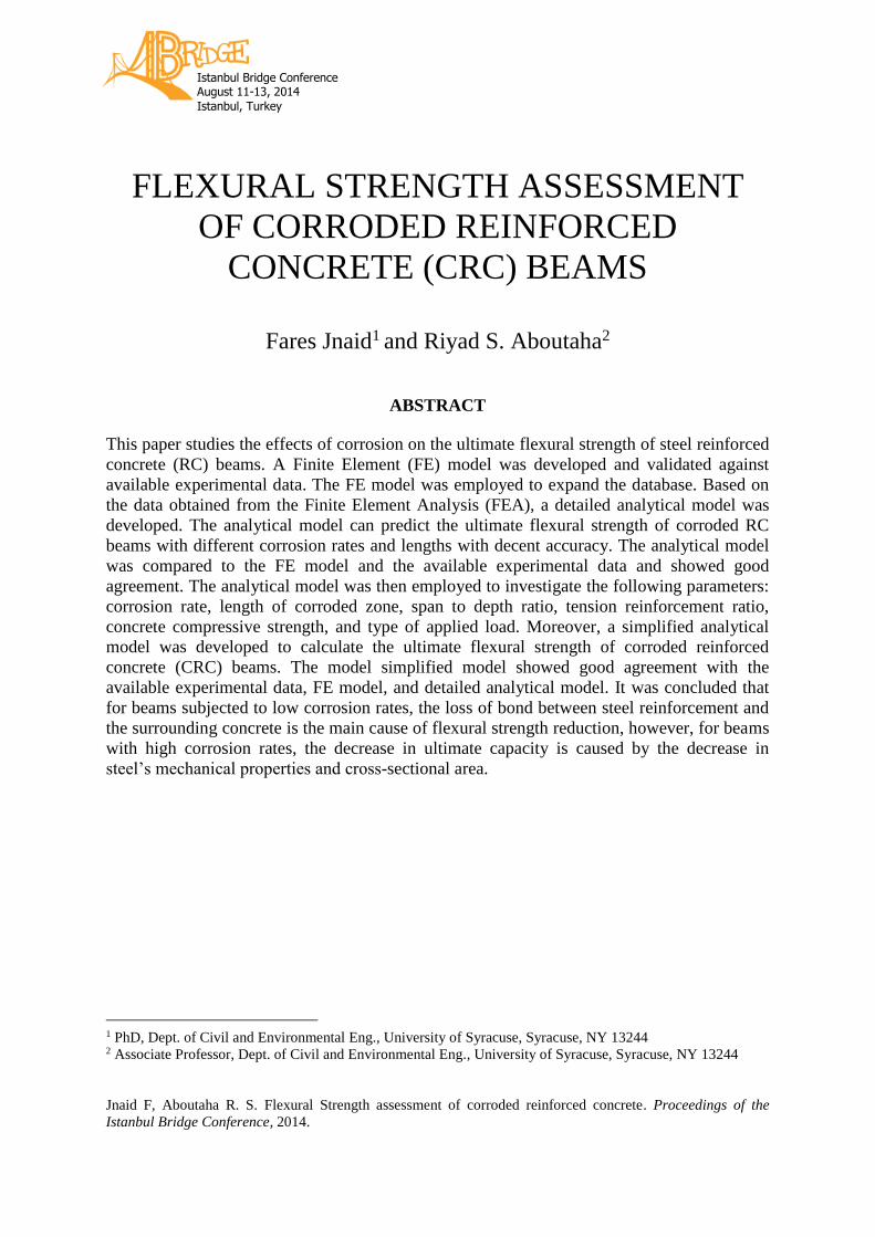
Figure 5 shows the effects of corrosion length on the ultimate flexural strength of CRC beams
of one of the cases studied. The vertical axis represents the values of Mcorr/M for a beam with
a span to depth ratio of 15. The vertical axis shows the ultimate capacity of corroded beams
as a percent of the reference beam, the horizontal axis stands for the corrosion length over the
total length of the beam. Each of the series represents a different corrosion rate. By
investigating all the studied cases, it was noted that when the corrosion length is less than
60% of the span length, the corrosion length has no effect on the ultimate strength of CRC
beams. This means that when the corrosion length is less than 60% of the span length, the
reduction in ultimate flexural strength is due to the decrease in steel cross-sectional-area and
strength caused by corrosion.
Figure 5. Effect of corrosion length on ultimate flexural strength
Effect of Corrosion Rate
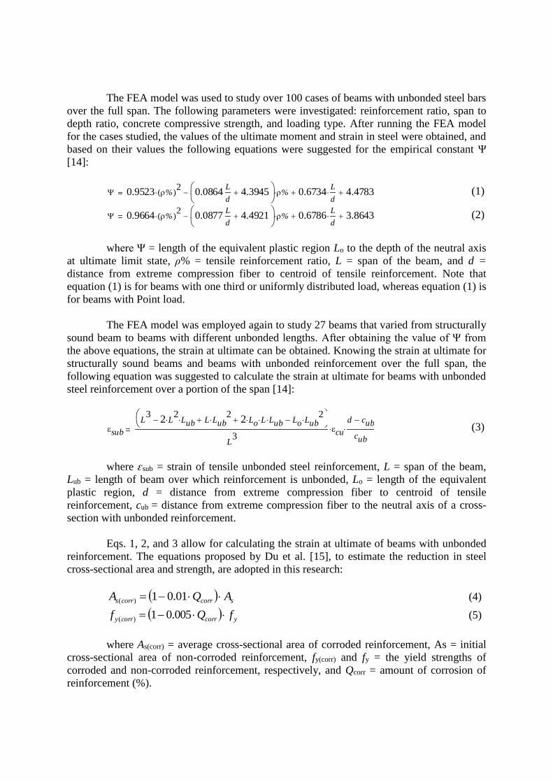
Figure 6 demonstrations the effects of corrosion rate on the ultimate flexural strength of
concrete beams with corroded steel reinforcement on the tension side of the beam. While the
vertical axis represents the values of Mcorr/M for a beam with a span to depth ratio of 15, the
horizontal axis shows the corrosion rate, and each of the series represents a different
corrosion length. Based on over 1000 cases studied, it was concluded that the increase in
corrosion rate is associated with a decrease in the ultimate flexural strength. However, when
the corrosion rate is higher than 40%, the decrease in ultimate flexural strength is due to the
decrease in steel cross-sectional area and strength. In other words, when the corrosion rate is
higher than 40%, the corrosion length has no effect on the ultimate flexural strength.
Figure 6. Effect of corrosion rate on ultimate flexural strength
Simplified Analytical Model
Building the Simplified Analytical Model
The detailed analytical model, after being verified against the available experimental data,
was employed to study over 2000 beams that varied from structurally sound beams to
unbonded and/or corroded beams under different corrosion lengths were studied. All of the
cases studied were analyzed by means of Mcorr/ub/M, which is the ratio of the ultimate moment
of a beam with corroded (unbonded) reinforcement over the ultimate moment of a
structurally sound beam with the same length and cross-section. Figure 7 shows some of the

cases studied where L/d = 15, f’c = 40 MPa (5.8ksi).
Figure 7. Ultimate capacity of RC beams with unbonded reinforcement as a percentage of structurally sound
beams
Based on all the cases studied, the following equation was presented:
𝛼 ≤
{
1 (𝜌% ≤ 0.35)
1 (𝐿𝑢𝑏
𝐿≤ 0.6)
0.08(𝜌%)2 − 0.56(𝜌%) + 2.25 −𝐿𝑢𝑏
𝐿 {
(𝜌% > 0.35)
(𝐿𝑢𝑏
𝐿> 0.6)
(6)
The above equation calculates the value of the moment reduction factor α based on
the unbonded length and the reinforcement ratio, and the ultimate flexural strength of
corroded beams can be calculated from the following equation:
𝑀𝑐𝑜𝑟𝑟 = 𝛼.𝑀𝑛𝑐 (7)
where 𝑀𝑛𝑐 = ultimate flexural strength of a fully bonded cross section with corroded
reinforcement.
(8)
where Cc = total compressive force of concrete at critical section, β1 = ratio of depth
of rectangular stress block to depth of neutral axis, c = distance from extreme compression
fiber to the neutral axis, Cs = total compressive force of compressive steel at critical section, d
= distance from extreme compression fiber to centroid of tensile reinforcement, d’ = distance
from extreme compression fiber to centroid of compressive reinforcement.
Validation of the Simplified Analytical Model
The results of the simplified analytical model were compared with the available experimental
data obtained by other researchers [2, 4, 9, 10, and 11]. Figure 8Figure 4 shows that the
simplified analytical model is able to predict the ultimate capacity of CRC beams with good
accuracy.
Mnc
Cc d1 c
2
Cs d d'( )

Figure 8. Comparison of simplified analytical model with the experimental results
Summary and Conclusions
- The FEA model, detailed analytical model, and simplified analytical model are able to
predict the ultimate flexural strength of CRC beams.
- When the corrosion rate is higher than 40%, the corrosion length has no effect on the
ultimate flexural strength.
- When the corrosion length is less than 60%, it has no effect on the ultimate flexural
strength.
- When the corrosion rate is higher than 40% or the corrosion length is less than 60%, the
reduction in the ultimate flexural strength is caused by the decrease in steel cross-
sectional area and strength due to corrosion.
References 1. Castel, A., Francois, R., and Arliguie, G. “Mechanical behavior of corroded reinforced concrete beams. Part
1: Experimental study of corroded beams,” Mater. Struct., Vol. 33, No. 9, 2000, pp. 539–544.
2. El Maaddawy, T., Soudki, K., and Topper, T., “Long-term performance of corrosion-damaged reinforced
concrete beams,” ACI Struct. J., V. 102, No. 5, 2005, pp. 649-656.
3. Du Y.G., Clark L.A., Chan A.H.C. “Impact of Reinforcement Corrosion on Ductile Behavior of Reinforced
Concrete Beams”, ACI Struct. J., V. 104, No. 3, 2007, pp. 285-293.
4. Wang, W. L., and Chen, J., “Residual Strengths of Reinforced Concrete Beams With Heavy Deterioration,”
Research Journal of Applied Sciences, Engineering and Technology, V. 3, No. 08, 2011, pp. 798-805.
5. Horrigmoe, G. and Hansen, T., “Assessment of the performance of structures attacked by reinforcement
corrosion”, International RILEM Symposium on Advances in concrete Through Science and Engineering,
Northwestern University, Evanston, Illinois, March 22-24, 2004.
6. Rodriguez, J., Ortega, L. M. and Casal, J., “Corrosion of reinforcing bars and service life of reinforced
concrete structures: Corrosion and bond deterioration”, International Conference on Concrete Across Borders,
Odense, Denmark, Vol. II, pp. 315-326, 1994.
7. Azher, S, A, “A prediction model for the residual flexural strength of corroded reinforced concrete beams”,

King Fahd University of Petroleum and Minerals, Dhahran, Saudi Arabia, 2005.
8. ANSYS 13.0, “Help Manual,” ANSYS, Inc., Canonsburg, Pennsylvania.
9. Cairns, J., and Zhao, Z., “Behavior of concrete beams with exposed reinforcement,” Proc. Instn Civ. Engrs
Structs & Bldgs, V. 99, No. 2, May, 1993, pp. 141-154.
10. Sharaf, H., and Soudki, K, “Strength Assessment of Reinforced Concrete Beams with Unbonded
Reinforcement and Confinement with CFRP Wraps,” 4th Structural Specialty Conference of the Canadian
Society for Civil Engineering, Montreal, Quebec, Canada, June 5-8, 2002.
11. Du Y.G., Clark L.A., Chan A.H.C. “Impact of Reinforcement Corrosion on Ductile Behavior of Reinforced
Concrete Beams”, ACI Struct. J., V. 104, No. 3, 2007, pp. 285-293.
12. Pannell, F. N., “The ultimate moment of resistance of unbonded prestressed concrete beam,” Mag. Concrete
Res., V. 21, No. 66, 1969, pp. 43-54.
13. Wang, X. H., and Liu, X. L., “Simplified methodology for the evaluation of the residual strength of corroded
reinforced concrete beams,” Journal of Performance for Constructed Facilities - ASCE, V. 24, No. 2, 2010,
pp. 108-119.
14. Jnaid, F., “Analysis of Corroded Steel Reinforced Concrete Beams,” PhD Dissertation, Syracuse University,
2014.
15. Du, Y. G., Clark, L. A., and Chan, A. H. C., “Residual capacity of corroded reinforcing bars.” Magazine of
Concrete Research, Vol. 57, No. 3, 2005, pp. 135-147.