flight controls — flap microswitches — incorporation of ... · a boeing australia company...
TRANSCRIPT
Nomad
7 Feb 2003 NMD--27--50AEROSPACE TECHNOLOGIES OF AUSTRALIA
ABN 56 008 622 008A BOEING AUSTRALIA COMPANY
Page 1 of 17
FLIGHT CONTROLS — FLAP MICROSWITCHES — INCORPORATIONOF MOD N835 (N22) & N874 (N24)
1. PLANNING INFORMATION
A. Effectivity
(1) Aircraft affected:
(a) N22 Series line sequence numbers 1 to 9, 11 to 29, 31, 33, 35, 37, 39 to 41, 43, 45, 47to 59, 61, 63, 65 to 70, 82 to 88, 90 to 95, 97, 100, 102 to 114, 116, 118, 125,126, 131to 134, 137, 138, 141, 143 to 158, 166 to 170.
NOTE
Mod N835 is not applicable to FAA Certificated N22S aircraft line sequencenumbers 159 to 165 inclusive. These aircraft are fitted with CO G582A.
(b) N24 Series line sequence numbers 10, 30, 32, 34, 36, 38, 42, 44, 46, 60, 62, 64, 71 to81, 89, 96, 98, 99, 101, 115, 117, 119 to 124, 127 to 130, 135, 136,139, 140, 142.
(2) Spares affected:None.
(3) It is a prerequisite that Mod N875 (N22) or N876 (N24)(Ref SB ANMD--57--13 Rev 1) ispreviously or concurrently fitted.
B. Reason
The current flap microswitches are individually installed in the wing and require to be adjusted forcorrect microswitch actuation whilst being installed, which results in a cumbersome method ofadjustment.Moisture contamination in the flapmicroswitches causing short circuits is still a possiblesource of uncommanded flap operations, despite incorporation of ASTA Modification N608 (RefANMD--27--40) which introduced plastic bagging around the flap microswitch installation.
C. Description
New hermetically sealed microswitches are installed in the wing as a pre-assembled microswitchassembly. Correct microswitch actuation can be adjusted and checked on a bench prior to fitmentto the wing so that the only adjustment required is for set-up of correct flap angle. The newmicroswitches being sealed will not short circuit due to moisture/water contamination, eliminatingthe flap microswitches as a cause of uncontrolled flap operations.
D. Compliance
(1) Incorporation of this Service Bulletin is mandatory.
(2) Tobe carried out at thenext 300hr inspection, or in conjunctionwith theembodiment ofServiceBulletin ANMD--57--13 Rev 1 (Mod N875 or N876).
Page No 1 2 3 4 5 6 7 8 9 10 11 12 13 14 15 16 17
Rev No 0 0 0 0 0 0 0 0 0 0 0 0 0 0 0 0 0
Nomad
7 Feb 2003 NMD--27--50AEROSPACE TECHNOLOGIES OF AUSTRALIA
ABN 56 008 622 008A BOEING AUSTRALIA COMPANY
Page 2 of 17
E. Approval
The requirement detailed herein has been approved by a person authorised under Civil AviationRegulation 35 and conforms to the Type Certification requirements.
F. Manpower
6 manhours.
G. Material – Price and Availability
Kits NMD--27--50--1 and NMD--27--50--2 are available free of charge upon request from NomadCustomer Support -- Boeing AerospaceSupport -- ASTA. Other parts to be locally sourced as noted.
H. Tooling
None.
I. Weight and Balance Change
None.
J. References
Maintenance Manual Chap 27--50--00, 27--50--03
K. Publications Affected
Maintenance ManualIllustrated Parts Catalogue
2. ACCOMPLISHMENT INSTRUCTIONS
A. PART 1 -- Removal of existing flap microswitch installation
WARNING
DO NOT OPERATE FLIGHT CONTROLS WITH CONTROL COMPONENTSDISCONNECTED OR WHEN PERSONNEL ARE WORKING IN THE AREACONCERNED. SERIOUS INJURY TO PERSONNEL OR DAMAGE TOCOMPONENTS AND STRUCTURE COULD OCCUR.
(1) Apply external power, set the flap circuit breakers and the battery switch to ON.
(2) Ensure cabin doors are shut and extend the flaps (Ref MM Chap 27–50–00).
(3) Set the battery switch to OFF, trip the flap circuit breakers and remove external power.
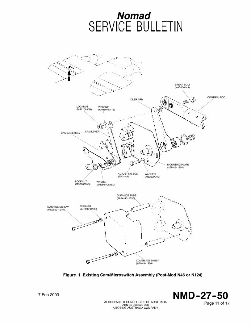
(4) Gain access to the cam/microswitch assembly (Ref Fig 1) at wsta 62.528 by opening theappropriate LH wing trailing edge doors.
(5) Post-Mod N46 (N22 Series) or N124 (N24 Series): Remove the moulded plastic cover byloosening the twoscrews (RefMMChap27--50--03, Fig 202, Sheet 2). Retain Cover Assembly1/N--45--1356 (screws, washers and distancepieces to be replaced if damaged, Ref IPCChap27--50--02. Fig 2).
Nomad
7 Feb 2003 NMD--27--50AEROSPACE TECHNOLOGIES OF AUSTRALIA
ABN 56 008 622 008A BOEING AUSTRALIA COMPANY
Page 3 of 17
(6) Post-Mod N608: Remove the plastic bag around the outboard end of the moulded cover andwiring loom (Ref MM Chap 27--50--03, Fig 203), and remove the moulded plastic cover byloosening the twoscrews (RefMMChap27--50--03, Fig 202, Sheet 2). Retain Cover Assembly1/N--45--1356 (screws, washers and distancepieces to be replaced if damaged, Ref IPCChap27--50--02 Fig 2).
CAUTION
ENSURE THAT THE CABLE IDENTS AT MICROSWITCH CONNECTIONS ARELEGIBLE. IF IDENTS ARE MISSING OR OBSCURE FIT NEW IDENTS ONDISCONNECTION.
(7) Disconnect the electrical connections at the microswitches, discard wires (idents C12E22 andC13D22) that connect between microswitches.
(8) Remove and discard shearbolt (NAS1304--9), locknut (MS21083N4) and washer(AN960PD416) from the cam lever and idler arm attachment to the flap control rod.
CAUTION
DO NOT REMOVE THE BOLT AT THE IMMEDIATE OUTBOARD FLAPCONTROL ROD JUNCTION.
(9) Remove and discard the locknut (MS21083N5) and washer (AN960PD516L) (Post-ModN46or N124) from the flap idler arm mounting bolt.
(10) Remove and retain the adjustment bolt (AN3--4A) and remove and discard washer(AN960PD10).
(11) Withdraw the cam assembly and mounting plate from the wing.
B. PART 2 -- Installation of Mod N835 (N22)
Cam/Microswitch assembly (1/N--45--1724) is supplied fully assembled with cams set. However, itis recommended that prior to installation on the wing correct activation of the microswitches bechecked as follows (Ref Figs 2, 3 and 4):
(1) Using a Multimeter, check microswitches B2, B1 and D as follows:
(a) Hold the cam lever fully counter-clockwise.
(b) Insert a 0.060 inch feeler gauge between microswitch B2 roller and its actuating cam.
(c) Confirm microswitch activates when the feeler gauge is inserted, and deactivates whenthe feeler gauge is withdrawn.
(d) Repeat steps (a) to (c) for microswitches B1 and D.
(2) If an adjustment is necessary proceed as follows:
(a) Slacken only those screws securing the cams needing adjustment.
(b) With cam lever rotated fully counter-clockwise place a 0.060 inch feeler gauge betweenthe microswitch roller and the lower step of the cam. Slide cam on the lever until the
Nomad
7 Feb 2003 NMD--27--50AEROSPACE TECHNOLOGIES OF AUSTRALIA
ABN 56 008 622 008A BOEING AUSTRALIA COMPANY
Page 4 of 17
switch just activates and torque tighten screws to 5--10 lb in. Recheck microswitchactivation of all three cams in the group and adjust as required.
(3) Using a Multimeter, check microswitches A2, A1 and C as follows:
(a) Hold the cam lever fully clockwise.
(b) Insert a 0.060 inch feeler gauge between microswitch A2 roller and its actuating cam.
(c) Confirm microswitch activates when the feeler gauge is inserted, and deactivates whenthe feeler gauge is withdrawn.
(d) Repeat steps (a) to (c) for microswitches A1 and C.
(4) If an adjustment is necessary proceed as follows:
(a) Slacken only those screws securing the cam needing adjustment.
(b) With cam lever rotated fully clockwise, place a 0.060 inch feeler gauge between themicroswitch roller and the lower step of the cam. Slide cam on the lever until the switchjust activates and torque tighten screws to 5--10 lb in. Recheck microswitch activationof all three cams in the group and adjust as required.
NOTE
S In the above steps, if a cam segment cannot be adjusted to activate themicroswitch, the cam should be removed and the adjustment/securing holescarefully enlarged.
S If the cam segment holes are enlarged, ensure the part is free from all burrs andsharp edges. Touch up exposed surfaces with Alodine.
(5) Pass special bolt (1/N--45--1740) through flap control rod and idler arm and secure with newlocknut (MS21083N4) and washer (NAS1149D463K), torque tighten to 30--40 lb in.
(6) Fit cam/microswitch assembly in place on the mounting bolt with the end of cam leverextending over the special flap control rod bolt (1/N--45--1740), securing to mounting bolt withnew locknut (MS21083N5) and washer (NAS1149D563K) and to the special bolt with washer(NAS1149D0363K) and split pin (MS24665--132), torque tighten locknut to 60--85 lb in.
(7) Secure mounting plate to aircraft structure using retained adjusting bolt (AN3--4A) and newwasher (NAS1149D0363K). Do not fully tighten bolt.
(8) Apply external power, set the flap circuit breakers and thebattery switch toON.Raise the flapsto 22_.
(9) Set the battery switch to OFF, trip the flap circuit breakers and remove external power.
(10) Remove backlash from the flap system by lifting the trailing edge.
(11) Rotate the cam/microswitch assembly mounting plate counter-clockwise to ensure release ofboth A1 and A2 microswitches. Then rotate the mounting plate clockwise until the eithermicroswitch A1 or A2 just activates. Tighten the adjusting bolt to 15--20 lb in.
Nomad
7 Feb 2003 NMD--27--50AEROSPACE TECHNOLOGIES OF AUSTRALIA
ABN 56 008 622 008A BOEING AUSTRALIA COMPANY
Page 5 of 17
(12) Connect wire leads as follows:
(a) Identify leads from microswitches (Ref Fig 4).
(b) Cut off crimped lugs (MS25036--148) from the aircraft cable wire ends and connect tothe external wire leads from microswitches (Ref Fig 4) using solder sleeves(M83519/1--2) or crimp splices (M81824/1--2).
NOTE
Stagger wire splices to prevent excessive build up of wire bundle diameter.
(c) Unusedwire leads frommicroswitches (Ref Fig 4) to be capped using insulatedwire caps(324484 AMP) and suitably stowed in a separate bundle.
(d) Secure cable to mounting plate with clip (NX3), screw (MS35206--246), nut(MS21044N08) and two washers (NAS1149DN832K). Secure aircraft wire bundle usingwaxed nylon cordage (WN25).
(13) Apply external power, set the flap circuit breakers and the battery switch to ON. Ensure cabindoors are closed.
(14) Functionally check the operation of the flap system over full range, including operation of theAUTO switch and stall warning system (Ref MM Chap 27--50--00 and MM Chap 31--52--00).
(15) With all adjustments completed, extend the flaps and install cover assembly (1/N--45--1356)over the microswitch and cam assembly. Close and secure the wing trailing edge doors.
(16) Check the operation of the landing gear up warning system (Ref MM Chap 32--60--00).
(17) Set the battery switch to OFF, trip the flap circuit breakers and remove external power.
C. PART 3 -- Installation of Mod N874 (N24)
Cam/Microswitch assembly (1/N--45--1725) is supplied fully assembled with cams set. However, itis recommended that prior to installation on the wing correct activation of the microswitches bechecked as follows (Ref Figs 5, 6 and 7):
NOTE
Microswitches B2 and A2 are not used, and there are only two cams per group tocheck/adjust.
(1) Using a Multimeter, check microswitches B1 and D as follows:
(a) Hold the cam lever fully counter-clockwise.
(b) Insert a 0.060 inch feeler gauge between microswitch B1 roller and its actuating cam.
(c) Confirm microswitch activates when the feeler gauge is inserted, and deactivates whenthe feeler gauge is withdrawn.
(d) Repeat steps (a) to (c) for microswitch D.
(2) If an adjustment is necessary proceed as follows:
(a) Slacken only those screws securing the cam needing adjustment.
Nomad
7 Feb 2003 NMD--27--50AEROSPACE TECHNOLOGIES OF AUSTRALIA
ABN 56 008 622 008A BOEING AUSTRALIA COMPANY
Page 6 of 17
(b) With cam lever rotated fully counter-clockwise, place a 0.060 inch feeler gauge betweenthe microswitch roller and the lower step of the cam. Slide cam on the lever until theswitch just activates and torque tighten screws to 5--10 lb in. Recheck microswitchactivation of the other cam in the group and adjust as required.
(3) Using a Multimeter, check microswitches A1 and C as follows:
(a) Hold the cam lever fully clockwise.
(b) Insert a 0.060 inch feeler gauge between microswitch A1 roller and its actuating cam.
(c) Confirm microswitch activates when the feeler gauge is inserted, and deactivates whenthe feeler gauge is withdrawn.
(d) Repeat steps (a) to (c) for microswitch C.
(4) If an adjustment is necessary proceed as follows:
(a) Slacken only those screws securing the cam needing adjustment.
(b) With cam lever rotated fully clockwise, place a 0.060 inch feeler gauge between themicroswitch roller and the lower step of the cam. Slide cam on the lever until the switchjust activates and torque tighten screws to 5--10 lb in. Recheck microswitch activationof the other cam in the group and adjust as required.
NOTE
S In the above steps, if a cam segment cannot be adjusted to activate themicroswitch, the cam should be removed and the adjustment/securing holescarefully enlarged.
S If the cam segment holes are enlarged, ensure the part is free from all burrs andsharp edges. Touch up exposed surfaces with Alodine.
(5) Pass special bolt (1/N--45--1740) through flap control rod and idler arm and secure with newlocknut (MS21083N4) and washer (NAS1149D463K), torque tighten to 30--40 lb in.
(6) Fit cam/microswitch assembly in place on the mounting bolt with the end of cam leverextending over the special flap control rod bolt (1/N--45--1740), securing to mounting bolt withnew locknut (MS21083N5) and washer (NAS1149D563K) and to the special bolt with washer(NAS1149D0363K) and split pin (MS24665--132), torque tighten locknut to 60--85 lb in.
(7) Secure mounting plate to aircraft structure using retained adjusting bolt (AN3--4A) and newwasher (NAS1149D0363K). Do not fully tighten bolt.
(8) Apply external power, set the flap circuit breakers (ACT and CONT) and the battery switch toON. Raise the flaps to fully UP.
(9) Trip the flap control (CONT) circuit breaker. Select the flap lever to fully DOWN. lower the flapsin small increments, by momentarily resetting the CONT circuit breaker until the flaps reach10_.
(10) Set the battery switch to OFF, trip the flap actuator (ACT) circuit breaker and remove externalpower.
(11) Remove backlash from the flap system by lifting the trailing edge.
(12) Rotate the cam assembly mounting plate counter-clockwise to ensure release of A1microswitch. Then rotate the mounting plate clockwise until the A1microswitch just activates.Tighten the securing bolt to 15--20 lb in.
Nomad
7 Feb 2003 NMD--27--50AEROSPACE TECHNOLOGIES OF AUSTRALIA
ABN 56 008 622 008A BOEING AUSTRALIA COMPANY
Page 7 of 17
(13) Connect wire leads as follows:
(a) Identify leads from microswitches (Ref Fig 7).
(b) Cut off crimped lugs (MS25036--148) from the aircraft cable wire ends and connect tothe external wire leads from microswitches (Ref Fig 7) using solder sleeves(M83519/1--2) or crimp splices (M81824/1--2).
NOTE
Stagger wire splices to prevent excessive build up of wire bundle diameter.
(c) Unused wire leads frommicroswitches and aircraft wire bundle (Ref Fig 7) to be cappedusing insulated wire caps (324484 AMP) and suitably stowed in separate bundles.
(d) Secure cable to mounting plate with clip (NX3), screw (MS35206--246), nut(MS21044N08) and two washers (NAS1149DN832K). Secure aircraft wire bundle usingwaxed nylon cordage (WN25).
(14) Apply external power, set the flap circuit breakers and the battery switch to ON. Ensure cabindoors are closed.
(15) Functionally check the operation of the flap system over full range, including operation of thestall warning system (Ref MM Chap 27--50--00 and MM Chap 31--52--00).
(16) With all adjustments completed, extend the flaps and install cover assembly (1/N--45--1356)over the microswitch and cam assembly. Close and secure the wing trailing edge doors.
(17) Check the operation of the landing gear up warning system (Ref MM Chap 32--60--00).
(18) Set the battery switch to OFF, trip the flap circuit breakers and remove external power.
Nomad
7 Feb 2003 NMD--27--50AEROSPACE TECHNOLOGIES OF AUSTRALIA
ABN 56 008 622 008A BOEING AUSTRALIA COMPANY
Page 8 of 17
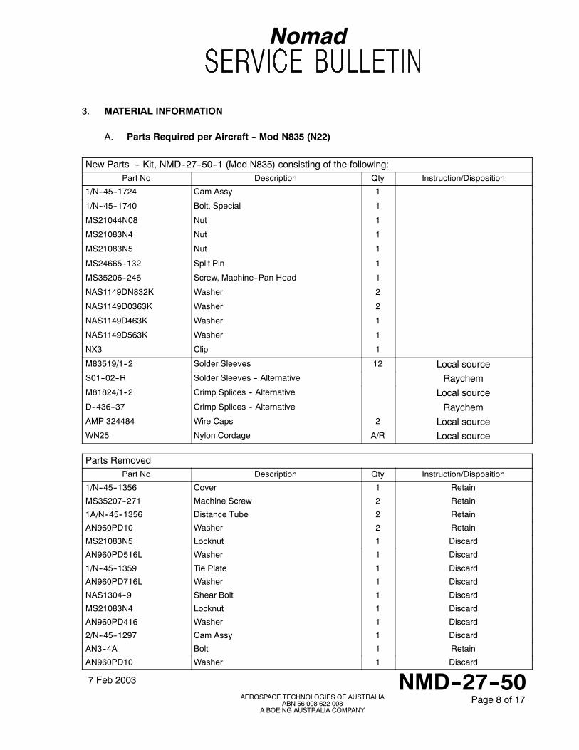
3. MATERIAL INFORMATION
A. Parts Required per Aircraft -- Mod N835 (N22)
New Parts -- Kit, NMD--27--50--1 (Mod N835) consisting of the following:Part No Description Qty Instruction/Disposition
1/N--45--1724 Cam Assy 1
1/N--45--1740 Bolt, Special 1
MS21044N08 Nut 1
MS21083N4 Nut 1
MS21083N5 Nut 1
MS24665--132 Split Pin 1
MS35206--246 Screw, Machine--Pan Head 1
NAS1149DN832K Washer 2
NAS1149D0363K Washer 2
NAS1149D463K Washer 1
NAS1149D563K Washer 1
NX3 Clip 1
M83519/1--2 Solder Sleeves 12 Local sourceS01--02--R Solder Sleeves -- Alternative RaychemM81824/1--2 Crimp Splices -- Alternative Local sourceD--436--37 Crimp Splices -- Alternative RaychemAMP 324484 Wire Caps 2 Local sourceWN25 Nylon Cordage A/R Local source
Parts RemovedPart No Description Qty Instruction/Disposition
1/N--45--1356 Cover 1 Retain
MS35207--271 Machine Screw 2 Retain
1A/N--45--1356 Distance Tube 2 Retain
AN960PD10 Washer 2 Retain
MS21083N5 Locknut 1 Discard
AN960PD516L Washer 1 Discard
1/N--45--1359 Tie Plate 1 Discard
AN960PD716L Washer 1 Discard
NAS1304--9 Shear Bolt 1 Discard
MS21083N4 Locknut 1 Discard
AN960PD416 Washer 1 Discard
2/N--45--1297 Cam Assy 1 Discard
AN3--4A Bolt 1 Retain
AN960PD10 Washer 1 Discard
Nomad
7 Feb 2003 NMD--27--50AEROSPACE TECHNOLOGIES OF AUSTRALIA
ABN 56 008 622 008A BOEING AUSTRALIA COMPANY
Page 9 of 17
Parts Removed (cont)Part No Description Qty Instruction/Disposition
1/N--45--1354 Mounting Plate 1 Discard
MSS25253--1 Microswitch 6 Discard
JV82 Actuator, Tandem, Roller 2 Discard
JV5 Actuator, Roller 2 Discard
B. Parts Required per Aircraft -- Mod N874 (N24)
New Parts -- Kit, NMD--27--50--2 (Mod N874) consisting of the following:Part No Description Qty Instruction/Disposition
1/N--45--1725 Cam Assy 1
1/N--45--1740 Bolt, Special 1
MS21044N08 Nut 1
MS21083N4 Nut 1
MS21083N5 Nut 1
MS24665--132 Split Pin 1
MS35206--246 Screw, Machine--Pan Head 1
NAS1149DN832K Washer 2
NAS1149D0363K Washer 2
NAS1149D463K Washer 1
NAS1149D563K Washer 1
NX3 Clip 1
M83519/1--2 Solder Sleeves 12 Local sourceS01--02--R Solder Sleeves -- Alternative RaychemM81824/1--2 Crimp Splices -- Alternative Local sourceD--436--37 Crimp Splices -- Alternative RaychemAMP 324484 Wire Caps 2 Local sourceWN25 Nylon Cordage A/R Local source
Nomad
7 Feb 2003 NMD--27--50AEROSPACE TECHNOLOGIES OF AUSTRALIA
ABN 56 008 622 008A BOEING AUSTRALIA COMPANY
Page 10 of 17
Parts RemovedPart No Description Qty Instruction/Disposition
1/N--45--1356 Cover 1 Retain
MS35207--271 Machine Screw 2 Retain
1A/N--45--1356 Distance Tube 2 Retain
AN960PD10 Washer 2 Retain
MS21083N5 Locknut 1 Discard
AN960PD516L Washer 1 Discard
1/N--45--1359 Tie Plate 1 Discard
AN960PD716L Washer 1 Discard
NAS1304--9 Shear Bolt 1 Discard
MS21083N4 Locknut 1 Discard
AN960PD416 Washer 1 Discard
1/N--45--1384 Cam Assy 1 Discard
AN3--4A Bolt 1 Retain
AN960PD10 Washer 1 Discard
1/N--45--1354 Mounting Plate 1 Discard
MSS25253--1 Microswitch 6 Discard
JV82 Actuator, Tandem, Roller 2 Discard
JV5 Actuator, Roller 2 Discard
4. SPECIAL TOOLS AND EQUIPMENT
None.
5. RECORDING ACTION
Record compliance with Service Bulletin NMD–27–50 in the Airframe Log Book.
Nomad
7 Feb 2003 NMD--27--50AEROSPACE TECHNOLOGIES OF AUSTRALIA
ABN 56 008 622 008A BOEING AUSTRALIA COMPANY
Page 11 of 17
Figure 1 Existing Cam/Microswitch Assembly (Post-Mod N46 or N124)
CONTROL RODIDLER ARM
CAM ASSEMBLY
COVER ASSEMBLY(1/N--45--1356)
DISTANCE TUBE(1A/N--45--1356)
MACHINE SCREW(MS35207--271)
WASHER(AN960PD10L)
MOUNTING PLATE(1/N--45--1354)
ADJUSTING BOLT(AN3--4A)
WASHER(AN960PD10)
LOCKNUT(MS21083N4)
WASHER(AN960PD416)
SHEAR BOLT(NAS1304--9)
LOCKNUT(MS21083N5)
WASHER(AN960PD516L)
CAM LEVER
Nomad
7 Feb 2003 NMD--27--50AEROSPACE TECHNOLOGIES OF AUSTRALIA
ABN 56 008 622 008A BOEING AUSTRALIA COMPANY
Page 12 of 17
MACHINE SCREW(MS35207--271)
WASHER(AN960PD10L)
DISTANCE TUBE(1A/N--45--1356)
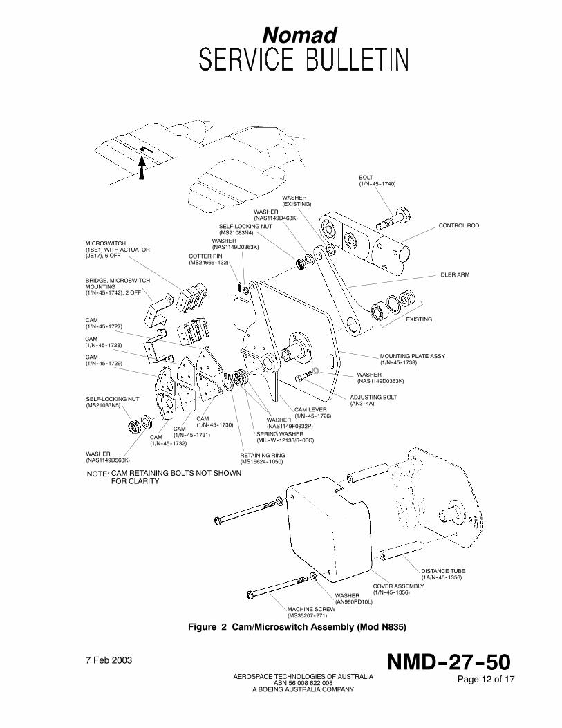
Figure 2 Cam/Microswitch Assembly (Mod N835)
CONTROL ROD
IDLER ARM
BOLT(1/N--45--1740)
WASHER(NAS1149D463K)
SELF-LOCKING NUT(MS21083N4)
WASHER(EXISTING)
COTTER PIN(MS24665--132)
MOUNTING PLATE ASSY(1/N--45--1738)
CAM LEVER(1/N--45--1726)
BRIDGE, MICROSWITCHMOUNTING(1/N--45--1742), 2 OFF
MICROSWITCH(1SE1) WITH ACTUATOR(JE17), 6 OFF
CAM(1/N--45--1730)
CAM(1/N--45--1731)CAM
(1/N--45--1732)
CAM(1/N--45--1727)
CAM(1/N--45--1728)
CAM(1/N--45--1729)
SELF-LOCKING NUT(MS21083N5)
WASHER(NAS1149D563K)
WASHER(NAS1149D0363K)
WASHER(NAS1149F0832P)
SPRING WASHER(MIL--W--12133/6--06C)
RETAINING RING(MS16624--1050)
CAM RETAINING BOLTS NOT SHOWNFOR CLARITY
NOTE:
EXISTING
COVER ASSEMBLY(1/N--45--1356)
ADJUSTING BOLT(AN3--4A)
WASHER(NAS1149D0363K)
Nomad
7 Feb 2003 NMD--27--50AEROSPACE TECHNOLOGIES OF AUSTRALIA
ABN 56 008 622 008A BOEING AUSTRALIA COMPANY
Page 13 of 17
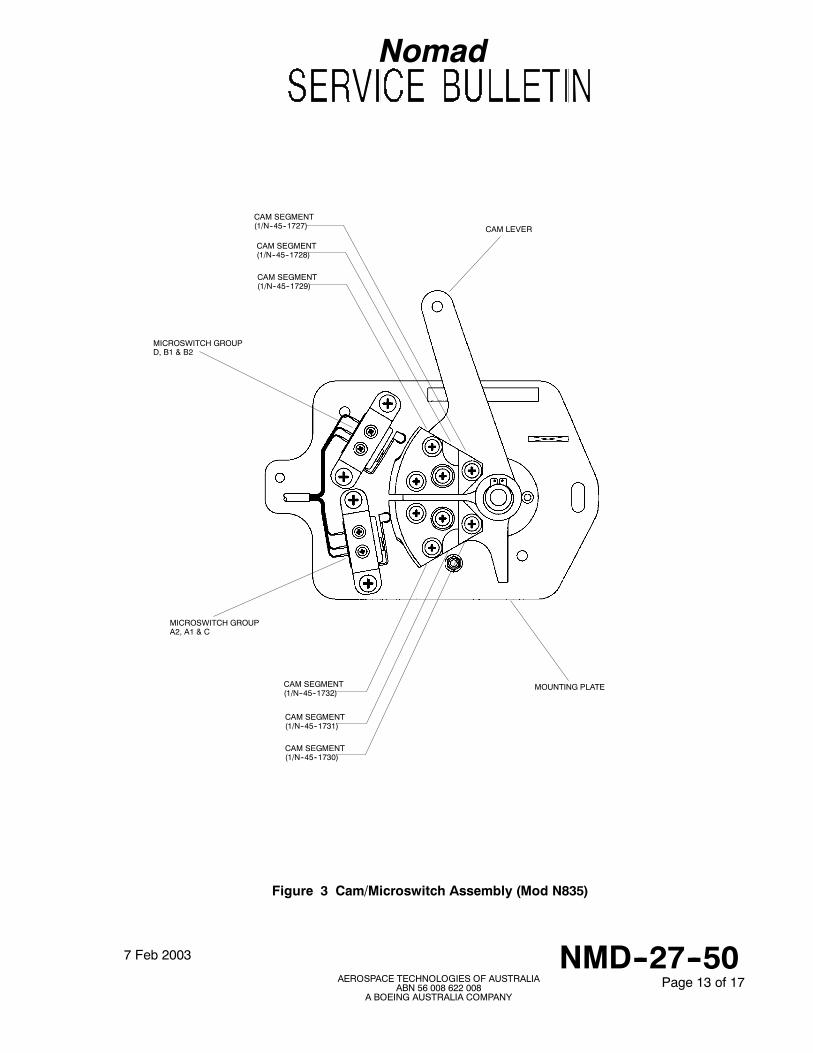
Figure 3 Cam/Microswitch Assembly (Mod N835)
CAM SEGMENT(1/N--45--1727)
CAM SEGMENT(1/N--45--1728)
CAM SEGMENT(1/N--45--1729)
CAM SEGMENT(1/N--45--1732)
CAM SEGMENT(1/N--45--1731)
CAM SEGMENT(1/N--45--1730)
CAM LEVER
MICROSWITCH GROUPD, B1 & B2
MICROSWITCH GROUPA2, A1 & C
MOUNTING PLATE
Nomad
7 Feb 2003 NMD--27--50AEROSPACE TECHNOLOGIES OF AUSTRALIA
ABN 56 008 622 008A BOEING AUSTRALIA COMPANY
Page 14 of 17
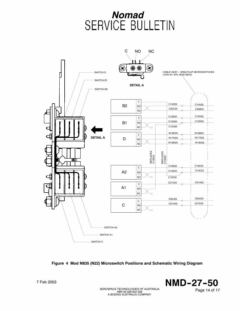
Figure 4 Mod N835 (N22) Microswitch Positions and Schematic Wiring Diagram
B2
B1
D
A2
A1
C
CABLE ASSY -- WING FLAP MICROSWITCHES(1A/N--81--970, MOD N875)
C
C
C
C
C
C
NO
NO
NO
NO
NO
NO
NC
NC
NC
NC
NC
NC
C14D20
C35C20
C15E20
C12G20
C12H20
W16E20
W17D20
W18D20
C19D20
C13E20
C13F20
C21C20
D22J20
D21H20
C14A22
C35B22
C15A22
C12D22
W16B22
W17A22
W18A22
C19A22
C13C22
C21A22
D22A22
D21D22
REPLA
CES
C12E22
REPLA
CES
C13D22
SWITCH A2
SWITCH A1
SWITCH C
SWITCH D
SWITCH B1
SWITCH B2
DETAIL A
DETAIL A
C NCNO
Nomad
7 Feb 2003 NMD--27--50AEROSPACE TECHNOLOGIES OF AUSTRALIA
ABN 56 008 622 008A BOEING AUSTRALIA COMPANY
Page 15 of 17
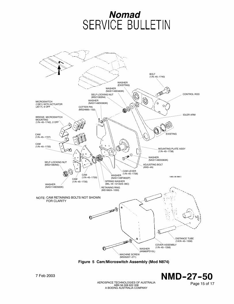
MACHINE SCREW(MS35207--271)
WASHER(AN960PD10L)
DISTANCE TUBE(1A/N--45--1356)
Figure 5 Cam/Microswitch Assembly (Mod N874)
CONTROL ROD
IDLER ARM
BOLT(1/N--45--1740)
WASHER(NAS1149D463K)
SELF-LOCKING NUT(MS21083N4)
WASHER(EXISTING)
COTTER PIN(MS24665--132)
MOUNTING PLATE ASSY(1/N--45--1738)
CAM LEVER(1/N--45--1726)
BRIDGE, MICROSWITCHMOUNTING(1/N--45--1742), 2 OFF
MICROSWITCH(1SE1) WITH ACTUATOR(JE17), 6 OFF
CAM(1/N--45--1730)
CAM(1/N--45--1735)
CAM(1/N--45--1727)
CAM(1/N--45--1733)
SELF-LOCKING NUT(MS21083N5)
WASHER(NAS1149D563K)
WASHER(NAS1149D0363K)
WASHER(NAS1149F0832P)
SPRING WASHER(MIL--W--12133/6--06C)
RETAINING RING(MS16624--1050)
CAM RETAINING BOLTS NOT SHOWNFOR CLARITY
NOTE:
EXISTING
COVER ASSEMBLY(1/N--45--1356)
ADJUSTING BOLT(AN3--4A)
WASHER(NAS1149D0363K)
Nomad
7 Feb 2003 NMD--27--50AEROSPACE TECHNOLOGIES OF AUSTRALIA
ABN 56 008 622 008A BOEING AUSTRALIA COMPANY
Page 16 of 17
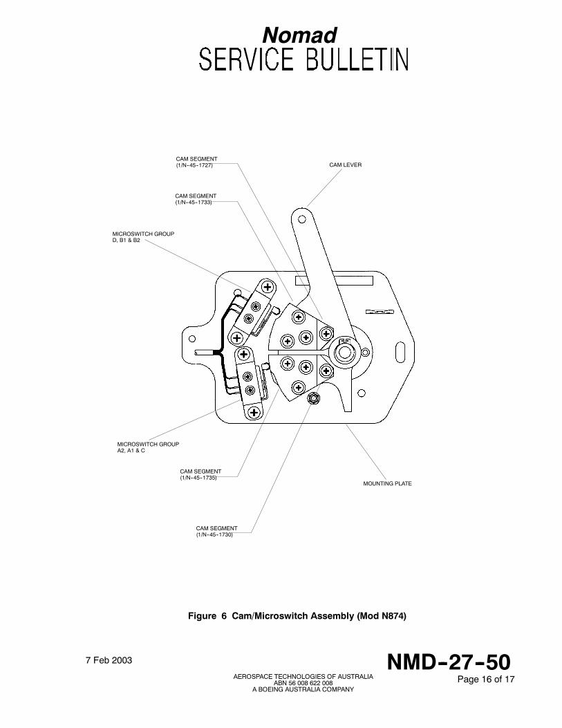
Figure 6 Cam/Microswitch Assembly (Mod N874)
CAM SEGMENT(1/N--45--1727)
CAM SEGMENT(1/N--45--1733)
CAM SEGMENT(1/N--45--1735)
CAM SEGMENT(1/N--45--1730)
CAM LEVER
MICROSWITCH GROUPD, B1 & B2
MICROSWITCH GROUPA2, A1 & C
MOUNTING PLATE
Nomad
7 Feb 2003 NMD--27--50AEROSPACE TECHNOLOGIES OF AUSTRALIA
ABN 56 008 622 008A BOEING AUSTRALIA COMPANY
Page 17 of 17
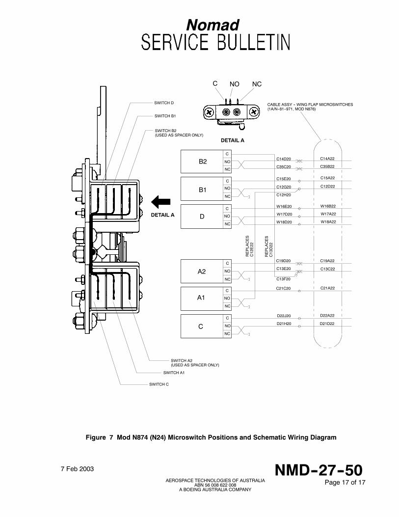
Figure 7 Mod N874 (N24) Microswitch Positions and Schematic Wiring Diagram
B2
B1
D
A2
A1
C
C
C
C
C
C
C
NC
NC
NC
NC
NC
NC
NO
NO
NO
NO
NO
NO
C14D20
C35C20
C15E20
C12G20
C12H20
W16E20
W17D20
W18D20
C19D20
C13E20
C13F20
C21C20
D22J20
D21H20
REPLA
CES
C12E22
REPLA
CES
C13D22
C14A22
C35B22
C15A22
C12D22
W16B22
W17A22
W18A22
C19A22
C13C22
C21A22
D22A22
D21D22
CABLE ASSY -- WING FLAP MICROSWITCHES(1A/N--81--971, MOD N876)
SWITCH A2(USED AS SPACER ONLY)
SWITCH A1
SWITCH C
SWITCH D
SWITCH B1
SWITCH B2(USED AS SPACER ONLY)
DETAIL A
DETAIL A
C NCNO
1