flight link technical setup document for the advanced ... · pdf fileflight link technical...
TRANSCRIPT

FLIGHT LINK TECHNICAL SETUP DOCUMENT VERSION 1.0.4 COPYRIGHT 2013 FLIGHT LINK LLC
1
Flight Link Technical Setup Document for the
Advanced Rotor Wing Control Package with
Microsoft Flight Simulator X (FSX)* The set up method described in this document attempts to maximize the realism of flying helicopters in FSX. This document also discusses briefly some characteristics of the flight models and representational aircraft graphics that are NOT at all similar to the “true” aircraft. This document can also be used to confirm the correct mechanical and electrical function of the Flight Link Helicopter Controls. Keep in mind that FSX is a simulation of reality. It is an imitation of actual physical properties. This document is only for technical reference, it is not to be used for flight instruction or training. *If you wish to use any other simulation software, please note that the first 5 steps of this document apply to any simulation software setup.
ENJOY!
FLIGHT LINK TECHNICAL SETUP DOCUMENT VERSION 1.0.4 COPYRIGHT 2013 FLIGHT LINK LLC
2
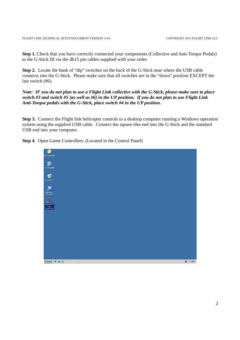
Step 1. Check that you have correctly connected your components (Collective and Anti-Torque Pedals) to the G-Stick III via the db15 pin cables supplied with your order. Step 2. Locate the bank of “dip” switches on the back of the G-Stick near where the USB cable connects into the G-Stick. Please make sure that all switches are in the “down” position EXCEPT the last switch (#6). Note: IF you do not plan to use a Flight Link collective with the G-Stick, please make sure to place switch #3 and switch #5 (as well as #6) in the UP position. If you do not plan to use Flight Link Anti-Torque pedals with the G-Stick, place switch #4 in the UP position. Step 3. Connect the Flight link helicopter controls to a desktop computer running a Windows operation system using the supplied USB cable. Connect the square-like end into the G-Stick and the standard USB end into your computer. Step 4. Open Game Controllers. (Located in the Control Panel)

FLIGHT LINK TECHNICAL SETUP DOCUMENT VERSION 1.0.4 COPYRIGHT 2013 FLIGHT LINK LLC
3
a) Select “Flight Link Helicopter Controls. Take note that “Status” indicates OK. b) Click the “Properties” button and review the graphic axes and button indicators. Take note that
the graphics will NOT be accurate because the controls have not been calibrated.

FLIGHT LINK TECHNICAL SETUP DOCUMENT VERSION 1.0.4 COPYRIGHT 2013 FLIGHT LINK LLC
4
c) Select the “Settings” tab and click the “Calibrate” button. At the prompt, center the Cyclic and click “Next”.
d) On this screen you can see the X and Y axis positions and values; this will be roll and pitch of
the Cyclic, respectively. Check the “Display raw data” value to see accurate control readings. Follow the on-screen instructions and click “Next”.

FLIGHT LINK TECHNICAL SETUP DOCUMENT VERSION 1.0.4 COPYRIGHT 2013 FLIGHT LINK LLC
5
e) Center the Cyclic handle and click “Next”.
f) On this screen you will see the Z axis, which is the Collective. Follow the on-screen
instructions and click “Next”.
g) On this screen you will see the X Rotation axis, which are the Anti-Torque pedals. Follow the
on-screen instructions and click “Next”.

FLIGHT LINK TECHNICAL SETUP DOCUMENT VERSION 1.0.4 COPYRIGHT 2013 FLIGHT LINK LLC
6
h) On this screen you will see the Y Rotation axis, which is the Throttle. Follow the on-screen
instructions and click “Next”.
i) On this screen you will see the Z Rotation axis, which is not used. Follow the on-screen
instructions and click “Next”.

FLIGHT LINK TECHNICAL SETUP DOCUMENT VERSION 1.0.4 COPYRIGHT 2013 FLIGHT LINK LLC
7
You are now finished with the Calibration of the Flight Link Helicopter Controls. Step 5. Apply the calibrated control settings and exit Game Controllers.
Step 6. Open Microsoft Flight Simulator X (FSX)

FLIGHT LINK TECHNICAL SETUP DOCUMENT VERSION 1.0.4 COPYRIGHT 2013 FLIGHT LINK LLC
8
Step 7. Open the “Options” menu, navigate to “Settings” and select “Controls”.
Step 8. On this screen confirm that Flight Link Helicopter Controls is selected and enabled. The sensitivity for all axes can be set here as well.
a) Confirm that “Simple” is selected. b) Confirm that the sensitivity for all axes is set to “127” or slider bar set to the far right. c) Confirm that the Null zone for all axes is set to “1” or slider bar set to the far left.

FLIGHT LINK TECHNICAL SETUP DOCUMENT VERSION 1.0.4 COPYRIGHT 2013 FLIGHT LINK LLC
9
Step 9. Click on the “Control Axes” tab and confirm that “Flight Link Helicopter Controls” is selected in the “Controller Type” menu.
Step 10. Assign Roll and Pitch to the X and Y axis, respectively. a) Double-Click “Ailerons axis”. At the new window click “clear” and move the Cyclic to the right or left. The X axis label should appear in the box.

FLIGHT LINK TECHNICAL SETUP DOCUMENT VERSION 1.0.4 COPYRIGHT 2013 FLIGHT LINK LLC
10
b) Double-Click “Elevator axis”. At the new window click “clear” and move the Cyclic to the forward or back. The Y axis label should appear in the box.
Step 11. Assign Yaw to the X Rotation axis. Double-Click “Rudder axis”. At the new window, click “clear” and move the Anti-Torque pedals. The X Rotation label should appear in the box.

FLIGHT LINK TECHNICAL SETUP DOCUMENT VERSION 1.0.4 COPYRIGHT 2013 FLIGHT LINK LLC
11
Step 12. Assign Propeller and Throttle to Y Rotation and Z axis, respectively. a) Double-Click “Engine 1 propeller axis”. At the new window click “clear” and move the Throttle. The Y Rotation label should appear in the box. This is misleading, but it is the correct procedure. Confirm the “Reverse” check box and a “check” it.
b) Double-Click “Engine 1 throttle axis”. At the new window click “clear” and move the collective. The Z axis label should appear in the box. This is misleading, but it is the correct procedure.

FLIGHT LINK TECHNICAL SETUP DOCUMENT VERSION 1.0.4 COPYRIGHT 2013 FLIGHT LINK LLC
12
Step 13. Confirm the alternative Throttle Control setting from the “Buttons/Keys” menu tab. Throttle “cut”, “decrease”, “increase” and “full” are assigned to F1, F2, F3, F4 respectively. These alternative controls are useful for manual adjustment of the throttle settings.
The Flight Link Helicopter controls are now correctly assigned to Microsoft Flight Simulator control axis. Step 14. Open the “Aircraft” menu and select “Realism settings”

FLIGHT LINK TECHNICAL SETUP DOCUMENT VERSION 1.0.4 COPYRIGHT 2013 FLIGHT LINK LLC
13
a) Confirm that the “Flight Model” settings are set to full “realistic” (the slider bars are moved to the far right.) The exception to this is the “General” slider, which should be one “notch” less than full. It is optional to leave “Crash Tolerance” to easy, which is done by moving the slider bar to the far left.
b) It is optional to set “Crashes and damage” to “Ignore”. The Flight Model can be affected by very subtle damage to the aircraft. c) Confirm that “Engines” has “Enable automixture” un-checked. This will affect the realism of the throttle. d) Confirm that “Flight controls” has “Autorudder” un-checked. This will affect flight realism as well. Step 15. Close the “Realism” settings menu. The helicopter flight model in now set for maximum realism (excluding crashes).

FLIGHT LINK TECHNICAL SETUP DOCUMENT VERSION 1.0.4 COPYRIGHT 2013 FLIGHT LINK LLC
14
Step 16. Open the “Aircraft” menu and choose “Select Aircraft”. Choose the Bell 206B.
a) Maximum RPM can be achieved by incrementing the Governor to maximum. To do this open the “Views” menu, navigate to “Instrument Panel” and select “Collective” b) Click on the “GOV RPM INC” graphic element and hold the mouse button down. c) Confirm that the RPM increases.

FLIGHT LINK TECHNICAL SETUP DOCUMENT VERSION 1.0.4 COPYRIGHT 2013 FLIGHT LINK LLC
15
d) Reduction in RPM can be achieved by decrementing the Governor. Click on the “GOV RPM DEC” graphic element and observe the RPM decrease. e) Confirm that the Throttle graphic only indexes to the “second to last” marker on the Collective grip. This is OK. The last marker does not affect RPM characteristics at all. The marker can be indexed with the mouse, but has no effect on flight performance. f) Alternatively you can use the F1, F2, F3 and F4 keys.

FLIGHT LINK TECHNICAL SETUP DOCUMENT VERSION 1.0.4 COPYRIGHT 2013 FLIGHT LINK LLC
16
Step 17. Open the “Aircraft” menu and choose “Select Aircraft”. Choose the Robinson R22 Beta II.
a) Maximum Throttle position does not occur until some percentage of the Collective is added. At this point Maximum RPM is also achievable.
FLIGHT LINK TECHNICAL SETUP DOCUMENT VERSION 1.0.4 COPYRIGHT 2013 FLIGHT LINK LLC
17
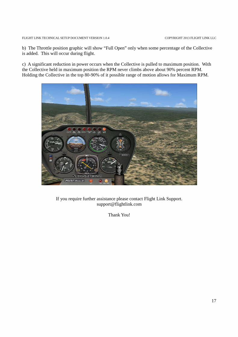
b) The Throttle position graphic will show “Full Open” only when some percentage of the Collective is added. This will occur during flight. c) A significant reduction in power occurs when the Collective is pulled to maximum position. With the Collective held in maximum position the RPM never climbs above about 90% percent RPM. Holding the Collective in the top 80-90% of it possible range of motion allows for Maximum RPM.
If you require further assistance please contact Flight Link Support. [email protected]
Thank You!