flight safety learjet 20 series pilot training manual volume 1
TRANSCRIPT

Courses for the Learjet 20 aircraft are taught at:
Tuscon Learning Center1071 E. Aero Park Blvd.Tuscon, Arizona 85706(800) 203-5627Fax: (520) 918-7111
Wichita (Learjet) Learning CenterTwo Learjet WayWichita, Kansas 67209(800) 491-9807Fax: (316) 943-0314
Copyright © 1998 by FlightSafety International, Inc. All rightsreserved. Printed in the United States of America.
FOR TRAINING PURPOSES ONLY
FOR TRAINING PURPOSES ONLY
NOTICE
The material contained in this training manual is based on informationobtained from the aircraft manufacturer’s Pilot Manuals andMaintenance Manuals. It is to be used for familiarization and trainingpurposes only.
At the time of printing it contained then-current information. In the eventof conflict between data provided herein and that in publications issuedby the manufacturer or the FAA, that of the manufacturer or the FAAshall take precedence.
We at FlightSafety want you to have the best training possible. Wewelcome any suggestions you might have for improving this manual orany other aspect of our training program.
iii


CONTENTS
MANEUVERS AND PROCEDURES
PERFORMANCE
WEIGHT AND BALANCE
CRM
v
NOVEMBER 1998 MAP-i
MANEUVERS AND PROCEDURESCONTENTS
Page
INTRODUCTION............................................................................................................. MAP-1
GENERAL........................................................................................................................ MAP-1
ABBREVIATIONS........................................................................................................... MAP-1
STANDARD OPERATING PROCEDURES ................................................................... MAP-2
General ...................................................................................................................... MAP-2
Responsibilities ......................................................................................................... MAP-2
Checklist Procedures ................................................................................................. MAP-2
Briefing Guides ......................................................................................................... MAP-3
Takeoff Procedures .................................................................................................... MAP-4
Climb and Cruise Procedures .................................................................................... MAP-4
Approach Planning .................................................................................................... MAP-5
Descent Procedures ................................................................................................... MAP-5
Approach Procedures ................................................................................................ MAP-5
Go Around/Balk Landing.......................................................................................... MAP-7
MANEUVERS.................................................................................................................. MAP-8
General ...................................................................................................................... MAP-8
Performance Standards.............................................................................................. MAP-8
Minimum Maneuvering Speeds ................................................................................ MAP-8
Power Settings......................................................................................................... MAP-10
Takeoff..................................................................................................................... MAP-10
Engine Failure Below V1 Speed ............................................................................. MAP-12
Engine Failure Above V1 Speed ............................................................................. MAP-13
FOR TRAINING PURPOSES ONLY
LEARJET 20 P ILOT TRA IN ING MANUAL
FlightSafetyinternational

Steep Turns.............................................................................................................. MAP-14
Slow Flight .............................................................................................................. MAP-15
Approach to Stall..................................................................................................... MAP-17
Emergency Descent................................................................................................. MAP-19
Visual Traffic Pattern, Two Engines........................................................................ MAP-20
Visual Traffic Pattern, Single Engine ...................................................................... MAP-20
Flaps Up Landing.................................................................................................... MAP-21
Precision Instrument Approach............................................................................... MAP-22
Nonprecision Instrument Approach ........................................................................ MAP-23
Circling Instrument Approach................................................................................. MAP-24
Go-Around/Balked Landing.................................................................................... MAP-26
Single-Engine Drift Down ...................................................................................... MAP-27
LEARJET 20 P ILOT TRA IN ING MANUAL
NOVEMBER 1998MAP-ii FOR TRAINING PURPOSES ONLY
FlightSafetyinternational
NOVEMBER 1998 MAP-iii
ILLUSTRATIONSFigure Title Page
MAP-1 Normal Takeoff................................................................................................ MAP-11
MAP-2 Rejected Takeoff .............................................................................................. MAP-12
MAP-3 Engine Failure At or Above V1 Speed ............................................................ MAP-13
MAP-4 Steep Turns ...................................................................................................... MAP-14
MAP-5 Slow Flight—Clean Configuration.................................................................. MAP-15
MAP-6 Slow Flight—Takeoff Configuration............................................................... MAP-16
MAP-7 Slow Flight—Landing Configuration.............................................................. MAP-16
MAP-8 Approach to Stall—Clean Configuration ........................................................ MAP-17
MAP-9 Approach to Stall—Takeoff Configuration ..................................................... MAP-18
MAP-10 Approach to Stall—Landing Configuration .................................................... MAP-18
MAP-11 Emergency Descent ......................................................................................... MAP-19
MAP-12 Visual Traffic Pattern....................................................................................... MAP-20
MAP-13 Flap Up Landing.............................................................................................. MAP-21
MAP-14 Precision Instrument Approach ....................................................................... MAP-22
MAP-15 Nonprecision Instrument Approach ................................................................ MAP-23
MAP-16 Circling Instrument Approach......................................................................... MAP-25
MAP-17 Go-Around/Balked Landing............................................................................ MAP-26
TABLE
Figure Title Page
MAP-1 Performance Standards ...................................................................................... MAP-9
FOR TRAINING PURPOSES ONLY
LEARJET 20 P ILOT TRA IN ING MANUAL
FlightSafetyinternational

MANEUVERS AND PROCEDURES
INTRODUCTIONThe general pilot information in this chapter is intended to supplement and expand upon in-formation in other sources. It is not intended to supercede any official publication. If there isany conflict between the information in this chapter and that in any official publication, the in-formation in the official publication takes precedence.
GENERALGeneral pilot information includes Standard Operating Procedures and the maneuvers normallyencountered during Learjet training and operations. The following abbreviations are used in thischapter.
ABBREVIATIONSAFM Airplane Flight Manual MMO Mach, Maximum
Operational
AGL Above Ground Level MSL Mean Sea Level
ATA Airport Traffic Area(Class D Airspace effective9/16/93) N1 Fan Speed
ATC Air Traffic Control PF Pilot Flying
CDI Course Deviation Indicator PIC Pilot in Command
COM/NAV Communication/Navigation PNF Pilot Not Flying
DH Decision Height SOP Standard OperatingProcedure
FAF Final Approach Fix
FL Flight Level VDP Visual Descent Point
HAA Height Above Airport VLE Velocity FlapsExtended
HAT Height Above Touchdown VMO Velocity MaximumOperational
NOVEMBER 1998 MAP-1FOR TRAINING PURPOSES ONLY
LEARJET 20 P ILOT TRA IN ING MANUAL
FlightSafetyinternational
IAF Initial Approach Fix V1 Critical EngineFailure Speed
KIAS Knots, Indicated Airspeed VR Rotation Speed
MAP Missed Approach Point VREF Reference Speed
MDA Minimum Descent Altitude V2 Takeoff SafetySpeed
MEA Minimum Enroute Altitude
STANDARD OPERATING PROCEDURES
GENERALStandard Operating Procedures (SOPs) are used to supplement the information in the AFM andFederal Air Regulations. Adherence to SOPs enhances individual and crew situational aware-ness and performance. SOPs may include assignment of responsibilities, briefing guides andprocedures to be followed during specific segments of flight. The SOPs in this section are notintended to be mandatory or to supersede any individual company SOPs. They are simply pro-vided as examples of good operating practices.
RESPONSIBILITIESPIC—The Pilot in Command is designated by the company for flights requiring more than onepilot. Responsible for conduct and safety of the flight. Designates pilot flying and pilot not fly-ing duties.
PF—The Pilot Flying controls the airplane with respect to heading, altitude, and airspeed andaccomplishes other tasks as directed by the PIC.
PNF—The Pilot Not Flying maintains ATC communications, obtains clearances, accomplisheschecklists, makes altitude callouts and other tasks as directed by the PIC.
All crewmembers are responsible for providing advice and counsel to the PIC. The PIC may chooseto accept or reject such advice. That is a prerogative of the PIC. But neither the PIC’s acceptancenor rejection of advice relieves other crewmembers of the responsibility of providing it.
CHECKLIST PROCEDURESNormally, the PF initiates all checklists. However, if the PNF thinks a checklist should be ac-complished, and the PF has not called for it, the PNF should prompt the PF. For example,“Ready for the Approach checklist, Captain?”
FlightSafety International recommends the use of the checklist challenge and response concept.Using Normal Procedures checklists, the PNF challenges the PF and the PF responds. UsingAbnormal or Emergency Procedures checklists, the PNF challenges the PF and, as a memoryaid, also gives the checklist item response. The PF then responds.
NOVEMBER 1998MAP-2 FOR TRAINING PURPOSES ONLY
LEARJET 20 P ILOT TRA IN ING MANUAL
FlightSafetyinternational
The PF may elect to have the PNF accomplish some Abnormal or Emergency Procedure check-lists on the PF’s command. In this case, the PNF gives the checklist item and response. The PFreplies with the response and the PNF accomplishes the action.
When a checklist has been completed, the PNF reports the checklist is complete and that he/sheis standing by with the next checklist. For example, “Approach checklist complete. Standingby with the Before Landing checklist.”
If an emergency occurs on takeoff after V1 speed and takeoff is continued, no checklist shouldbe initiated before the airplane reaches a safe altitude above the ground; at least 400 feet.
BRIEFING GUIDES
GeneralWhile the Learjet AFM does not specifically require before takeoff and approach briefings, suchbriefings are appropriate under some circumstances. The briefing guides presented below shouldbe used when flying with unfamiliar crewmembers or any other time the PIC believes they arenecessary.
It should be noted that many of these items can, and should, be briefed well before engine start.Many of them can be discussed before arriving at the airplane.
Pretakeoff BriefingThe pretakeoff briefing should address the following items:
• Type of takeoff; rolling or standing, flap setting, etc.
• Review takeoff data to include power setting and speeds
• Procedures to be used in the event of an emergency before or after V1 speed including emer-gency return procedures
• Headings and altitudes to be flown during the departure including restrictions, if any
• Radio, navigational systems and flight director settings
• Anti-icing requirements, if applicable
• Specific PNF duties and callouts. (See “Takeoff Procedures,” later in this section for ad-ditional information.)
• A request for “And questions?” directed to all cockpit crewmembers.
Approach BriefingThe approach briefing should be completed before starting descent and address the followingitems. The PF normally transfers airplane control to the PNF during the briefing.
• Approach to be used and backup approach, if available
• Special procedures to be used during the approach, such as circling approach procedures,interception of a radial from an arc, VDP, etc.
• Altitudes of IAF, FAF, stepdowns, sector and obstacles
NOVEMBER 1998 MAP-3FOR TRAINING PURPOSES ONLY
LEARJET 20 P ILOT TRA IN ING MANUAL
FlightSafetyinternational
• Minimums (DH, MDA), (HAT, HAA), radio altimeter setting
• Missed approach point and procedures, timing to MAP/VDP
• Radio (COM/NAV) setup desired
• Anti-icing requirements. Specific PNF duties and callouts. (See “Approach Procedures,”later in this section, for additional information.)
• The procedure for transitioning to visual flight
• A request for “Any questions?” directed to all cockpit crewmembers
At the completion of the Approach briefing, the PF announces “Approach briefing complete,”and reassumes control of the airplane if control has been transferred to the PNF.
TAKEOFF PROCEDURESWhen cleared for takeoff, the PNF reports “Before Takeoff checklist complete, cleared fortakeoff.” The PF advances power toward the takeoff power setting, the PNF taps PF’s hand andmakes the final power setting.
At initial airspeed indication, the PNF cross-checks airspeed indicators and reports “Airspeedalive.” PF releases nosewheel steering.
At V1 speed, the PNF calls “Vee One.” The PF releases the thrust levers and puts both hands onthe control column.
At VR, the PNF calls “Rotate.” The PF rotates airplane to a 9° noseup pitch attitude.
With positive rate of climb, the PF calls “Positive rate, gear up.” The PNF positions the gearhandle to up and calls “Gear selected up.” The PNF monitors the gear while it is retracting andreports “Gear up,” when retraction is complete.
Before VFE (V2 plus 30 knots minimum), the PF calls, “Flaps up, yaw damper on, and AfterTakeoff checklist.” The PNF positions the flap handle to up and calls “Flaps selected up.” ThePNF monitors the flaps while they are retracting and reports “Flaps up,” when retraction is com-plete. PNF accomplishes the After Takeoff checklist.
CLIMB AND CRUISE PROCEDURESThe PNF announces all assigned altitudes and sets them in the altitude alerter. The PNF alsocalls out 1,000 feet above, or below, all assigned altitudes and altitude restrictions. These callsnormally are made by stating the existing altitude and the assigned altitude or restriction. Forexample, “Through 9,000 feet, cleared to 8,000,” or “Through flight level 460 for 470.” The PNFalso announces other significant altitudes, such as, “Through 18,000 feet, altimeter 29.92,” or,“Flight lever 410, going on oxygen.”
The PF periodically announces his intentions and targets throughout the flight, such as “Accel-erating to 250 knots,” “Turning right to 260 degrees and descending to 3,000 feet,” “We’ll holdthis heading until intercepting the 090 degree radial and then turn left to the station.”
NOVEMBER 1998MAP-4 FOR TRAINING PURPOSES ONLY
LEARJET 20 P ILOT TRA IN ING MANUAL
FlightSafetyinternational

Any change in cockpit function is announced by the pilot making the change and acknowledgedby the other pilot. For example, the PNF announces, “VOR number two set to Springfield andidentified.” PF acknowledges, “VOR two on Springfield.” PF announces, “Autopilot engagedand coupled in climb and heading modes.” PNF acknowledges, “Roger.”
Transfer of airplane control is announced by the pilot initiating the change and acknowledgedby the pilot assuming control. Specific target values are provided to the pilot assuming control.For example, the PF announces, “Take the airplane for a minute. We’re climbing at 250 knotsto 7,000 on a vector to the 045 radial.” PNF acknowledges, “I’ve got the airplane, climbing at250 to 7,000 on this heading until intercepting the 045 radial.”
APPROACH PLANNINGApproach planning and briefing should be accomplished during cruise. Review hazardous ter-rain, MEAs, and minimum sector altitudes. Complete and review performance data to includeVREF speed, landing distance, approach climb speed, and power setting.
The PF directs the PNF to obtain destination weather or obtains it himself. If the PNF obtainsthe weather, the PF normally assumes ATC Communications while the PNF is obtaining weather.In either case, after checking weather, the pilot who did so briefs the other pilot on the desti-nation weather, the expected approach, and any other significant information.
If a VDP has not been published, a “time to see the runway” may be computed as follows. Takethe MDA, divided by 10, and subtract that, in seconds, from the time from the FAF to the MAP.For example, assume the MDA is 400 feet and the time from the FAF to the MAP is 1 minuteand 45 seconds. Four hundred, divided by 10 equals 40. Subtracting that from 1:45 equals 1:05from the FAF to see the runway. If the runway is not in sight at the end of that time, either afaster than normal rate of descent is required, or the airplane lands beyond the normal touch-down zone.
Normally, ATC determines when a descent may be started. However, descents may sometimesbe started at the PF’s discretion. To determine how far out to start descent for an approach, use3 times the altitude to be lost, divided by 1,000. For example, to lose 40,000 feet, 3 times 40,000equals 120,000, divided by 1,000 equals 120 miles out to start descent.
The Descent checklist should be started before, or early in, the descent to permit proper wind-shield heat and pressurization system operation.
Descent below flight level 180 will not be started before obtaining a local area altimeter setting.
DESCENT PROCEDURESThe same procedures used during climb and cruise are used during descent. The PNF accom-plishes the Descent checklists, as directed by the PF, and makes altitude callouts to include thetransition level and 10,000 feet.
APPROACH PROCEDURESThe PF initiates the Approach checklist when descending out of 18,000 feet or when within 50miles of the destination airport. The checklist is accomplished so as to not interfere with thevisual lookout for other traffic.
NOVEMBER 1998 MAP-5FOR TRAINING PURPOSES ONLY
LEARJET 20 P ILOT TRA IN ING MANUAL
FlightSafetyinternational

Configuration changes during the approach are accomplished using the same crew coordina-tion techniques used after takeoff. The PF calls for a configuration change. The PNF acknowl-edges, selects the switch position, monitors and reports when gear and flaps are in the selectedpositions.
The Approach checklist is completed and the airplane slowed to VREF + 40 knots (minimum)before reaching the IAF.
Over the IAF, for other than a straight-in approach, the PF terms outbound, calls for flaps 8°,slows the airplane to VREF + 30 knots (minimum), and begins a descent, if necessary. The PNFstarts timing, announces the time to be flown and the outbound course, or heading, and altitude,if an attitude change is required.
If a procedure turn is to be made, any accepted procedure turn maneuver may be used. At theexpiration of the time from the IAF, the PNF announced that time is up, the direction of turn,and the next heading. For example, “Time’s up, left turn now to 045 degrees.” Wings-level out-bound in the procedure turn, the PNF starts timing, announces the time to be flown and the nextheading and altitude. At the expiration of the procedure turn outbound time, the PNF announcesthe time is up, the direction of turn, the next heading and altitude. For example, “Time’s up,right turn now to 225° and cleared down to 3,000.”
Approaching the final approach course, the PNF monitors the CDI or bearing pointer and re-ports “CDI alive,” or “Within 5° of the inbound course.”
Established on final approach (within 2 1/2° for all approaches), the PF calls forflaps 20°, slows the airplane to VREF + 20 knots (minimum), and begins a descent,if necessary. After the flaps have been set to 20°, the PF calls “Gear down, BeforeLanding checklist.” The PNF extends the landing gear, completes the BeforeLanding checklist up to flaps down and reports, “Before Landing Checklist com-plete to full flaps.”
Over the FAF, on a two-engine, straight-in approach, the PF calls for flaps 40°, slows the air-plane to VREF (minimum), and begins a descent. (For a single-engine, or circling approach, theflaps remain at 20° until the landing is assured.) The PNF begins timing, if necessary, extendsthe flaps and completes the Before Landing checklist. The PNF also confirms that the COM/NAVradios are set properly, checks the flight instruments, airspeed bugs, altitude alerter, radio al-timeter setting and MDA or DH. The PNF then reports, “Before Landing checklist complete,no flags, cleared to descend to ________ feet.”
After passing the FAF, the PNF begins looking for visual references outside the airplane. How-ever, he/she also monitors the instruments and calls out significant deviations such as 1 dot, ormore, deflection on the CDI or glide slope and airspeed variations greater than -0 to +10 knotsfrom VREF. If the PF does not respond to the callout, the PNF repeats it. If the PF does not re-spond to the second callout, the PNF assumes the PF has been incapacitated and announces thathe/she (the PNF) is taking control of the airplane.
NOVEMBER 1998MAP-6 FOR TRAINING PURPOSES ONLY
LEARJET 20 P ILOT TRA IN ING MANUAL
FlightSafetyinternational
The PNF calls out the time to the VDP/MAP and 1,000, 500, and 100 feet above MDA or DH,and reaching MDA or DH. The PNF also reports visual contact with the ground such as, “Vi-sual contact, no runway yet,” “Approach lights in sight at 11 o’clock,” or “Runway in sight straightahead.” If a runway in sight has not been called by the PNF at MAP or DH, the PNF calls, “MAPor DH, no contact.”
Approaching minimums, or the missed approach point, the PF begins cross-checking outsidethe airplane for visual references. When satisfied that visual references are adequate for land-ing, the PF announces, “I’m going visual,” or “Going outside.” At this point, the PNF directshis attention primarily inside the airplane, while cross-checking outside, and calls airspeed, de-scent rate, and altitude. The purpose is to provide the PF, verbally, the same information he/shewould have if still on instruments.
Airspeed should be called as plus or minus VREF, descent rate as up or down and altitude abovethe ground. For example, “Plus 5, down 500, 100 feet,” indicates the airspeed is VREF plus 5knots, the airplane is descending at 500 feet per minute and is 100 feet above the ground.
GO AROUND/BALKED LANDINGIf a go around/balked landing is necessary, the PF calls “Going around”, set power to take-offthrust and simultaneously establish a 9° noseup pitch attitude. Selecting the flight director toGo-around mode will disengage the auto-pilot and set the pitch bars to 9 degrees. Spoilers willbe checked retracted and flaps set to 20 degrees. The PNF will confirm spoilers and flaps set aswill call out the direction of turn if one is required, along with the missed approach heading andaltitude. The PNF notifies ATC of the missed approach.
NOVEMBER 1998 MAP-7FOR TRAINING PURPOSES ONLY
LEARJET 20 P ILOT TRA IN ING MANUAL
FlightSafetyinternational
MANEUVERS
GENERALThis section contains a description of most of the maneuvers that are likely to be encounteredduring Learjet training and operational flying. While there is always more than one way to flyan airplane, these procedures have been developed over many years of Learjet operations. Theyhave proven to be safe, efficient, and readily manageable. These procedures are consistent withthe AFM. However, if a conflict should develop between these procedures and those in the AFM,the AFM procedures should be used.
PERFORMANCE STANDARDSThe performance standards in Table MAP-1 should be maintained during all Learjet flightoperations.
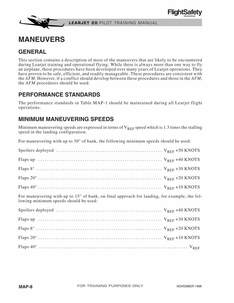
MINIMUM MANEUVERING SPEEDSMinimum maneuvering speeds are expressed in terms of VREF speed which is 1.3 times the stallingspeed in the landing configuration.
For maneuvering with up to 30° of bank, the following minimum speeds should be used:
Spoilers deployed . . . . . . . . . . . . . . . . . . . . . . . . . . . . . . . . . . . . . . . . . . . . . . . . VREF +50 KNOTS
Flaps up . . . . . . . . . . . . . . . . . . . . . . . . . . . . . . . . . . . . . . . . . . . . . . . . . . . . . . . . VREF +40 KNOTS
Flaps 8° . . . . . . . . . . . . . . . . . . . . . . . . . . . . . . . . . . . . . . . . . . . . . . . . . . . . . . . . . VREF +30 KNOTS
Flaps 20° . . . . . . . . . . . . . . . . . . . . . . . . . . . . . . . . . . . . . . . . . . . . . . . . . . . . . . . . VREF +20 KNOTS
Flaps 40° . . . . . . . . . . . . . . . . . . . . . . . . . . . . . . . . . . . . . . . . . . . . . . . . . . . . . . . . VREF +10 KNOTS
For maneuvering with up to 15° of bank, on final approach for landing, for example, the fol-lowing minimum speeds should be used:
Spoilers deployed . . . . . . . . . . . . . . . . . . . . . . . . . . . . . . . . . . . . . . . . . . . . . . . . VREF +40 KNOTS
Flaps up . . . . . . . . . . . . . . . . . . . . . . . . . . . . . . . . . . . . . . . . . . . . . . . . . . . . . . . . VREF +30 KNOTS
Flaps 8° . . . . . . . . . . . . . . . . . . . . . . . . . . . . . . . . . . . . . . . . . . . . . . . . . . . . . . . . . VREF +20 KNOTS
Flaps 20° . . . . . . . . . . . . . . . . . . . . . . . . . . . . . . . . . . . . . . . . . . . . . . . . . . . . . . . . VREF +10 KNOTS
Flaps 40° . . . . . . . . . . . . . . . . . . . . . . . . . . . . . . . . . . . . . . . . . . . . . . . . . . . . . . . . . . . . . . . . . . . VREF
NOVEMBER 1998MAP-8 FOR TRAINING PURPOSES ONLY
LEARJET 20 P ILOT TRA IN ING MANUAL
FlightSafetyinternational
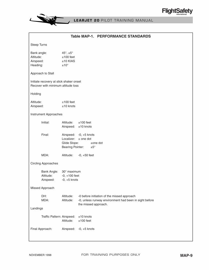
Steep Turns
Bank angle: 45°, ±5°Altitude: ±100 feetAirspeed: ±10 KIASHeading: ±10°
Approach to Stall
Initiate recovery at stick shaker onsetRecover with minimum altitude loss
Holding
Altitude: ±100 feetAirspeed: ±10 knots
Instrument Approaches
Initial: Altitude: ±100 feetAirspeed: ±10 knots
Final: Airspeed: -0, +5 knotsLocalizer: ± one dotGlide Slope: ±one dotBearing Pointer: ±5°
MDA: Altitude: -0, +50 feet
Circling Approaches
Bank Angle: 30° maximumAltitude: -0, +100 feetAirspeed: -0, +5 knots
Missed Approach
DH: Altitude: -0 before initiation of the missed approachMDA: Altitude: -0, unless runway environment had been in sight before
the missed approach.Landings
Traffic Pattern: Airspeed: ±10 knotsAltitude: ±100 feet
Final Approach: Airspeed: -0, +5 knots
NOVEMBER 1998 MAP-9FOR TRAINING PURPOSES ONLY
LEARJET 20 P ILOT TRA IN ING MANUAL
FlightSafetyinternational
Table MAP-1. PERFORMANCE STANDARDS
POWER SETTINGSActual power settings vary depending upon the temperature, pressure altitude, and airplane grossweight. The following target settings are approximate, but may be used to provide a startingpoint to determine the actual power setting.
Below 10,000 MSL, 78% rpm1 to maintain 200 KIAS, 83% rpm to maintain 250 KIAS.
Between 10,000 MSL and FL 250, 84% rpm to maintain 250 KIAS.
TAKEOFFEither 8 or 20° of flaps may be used for takeoff. The normal, standing takeoff (Figure MAP-1)must be used to achieve the performance specified in the AFM. If the runway available is at least10 percent longer than the planned takeoff distance, a rolling takeoff may be used. The proce-dures are the same except for a standing takeoff, power is set before brake release. For a rollingtakeoff, the brakes are released before the power is set. During a rolling takeoff, takeoff powermust be set before the runway remaining equals the takeoff distance.
Normally, before VFE (V2 plus 30 knots minimum), the flaps are retracted and the After Take-off checklist is accomplished. However, if traffic conditions warrant, the After Takeoff check-list may be delayed until the airplane is clear of local traffic.
Approaching 200 knots, the PF should adjust pitch and power if necessary, to maintain 200 knotsor less within the ATA (Class D Airspace). For passenger comfort and ease of airplane control,it is recommended that the pitch attitude not exceed 20° noseup.
The maximum continuous climb power setting is 95% rpm below 10,000 feet and 98% above10,000 feet.
NOVEMBER 1998MAP-10 FOR TRAINING PURPOSES ONLY
LEARJET 20 P ILOT TRA IN ING MANUAL
FlightSafetyinternational

NOVEMBER 1998 MAP-11FOR TRAINING PURPOSES ONLY
LEARJET 20 P ILOT TRA IN ING MANUAL
FlightSafetyinternational
VR
BEFORE VFE(V2 PLUS 30 KT MINIMUM)
BEFORE TAKING RUNWAYCHECKLISTS COMPLETE THROUGH TAKEOFF CHECKLIST
BEFORE TAKEOFF1. PF HOLDS BRAKES AND ADVANCES POWER1. PNF SETS TAKEOFF POWER
INITIAL AIRSPEED INDICATION1. PNF CALLS "AIRSPEED"2. PF DISENGAGES NOSEWHEEL STEERING
80 KIASPNF MONITORS AND ADJUSTS TAKEOFF POWER
V11. PNF CALLS "VEE ONE"2. PF RELEASES THRUST LEVERS
1. PNF CALLS "ROTATE"2. PF ROTATES AIRPLANE TO 9˚ NOSE-UP PITCH ATTITUDE
POSITIVE RATE OF CLIMB1. PF CALLS "GEAR UP"2. PNF RETRACTS LANDING GEAR
1.PF CALLS "FLAPS UP, AFTER TAKEOFF CHECKLIST"2. PNF ACCOMPLISHES AFTER TAKEOFF CHECKLIST
APPROACHING 200 KIAS
PF ADJUSTS PITCH AND POWER
CLEAR OF ATA/CLASS D AIRSPACE 1. PF SETS MAXIMUM CONTINUOUS CLIMB POWER AND ACCELERATES AIRPLANE TO 250 KIAS
YAW DAMPER
Figure MAP-1. Normal Takeoff

ENGINE FAILURE BELOW V1 SPEEDIf an engine fails below V1 speed (Figure MAP-2), the takeoff must be aborted. The PF simul-taneously reduces power to idle, applies maximum braking and deploys the spoilers. The dragchute or thrust reversers (if installed) are deployed if necessary.
Takeoffs may be aborted for malfunctions other than engine failure, however, the same proce-dures should normally be used.
NOVEMBER 1998MAP-12 FOR TRAINING PURPOSES ONLY
LEARJET 20 P ILOT TRA IN ING MANUAL
FlightSafetyinternational
BEFORE TAKING RUNWAY
TO 80 KIAS
INITIAL TAKEOFF ROLL1. STANDING OR ROLLING TAKEOFF PROCEDURES
INITIAL AIRSPEED INDICATION1. PNF CALLS "AIRSPEED"2. PF DISENGAGES NOSEWHEEL STEERING
1. PNF MONITORS AND ADJUSTS TAKEOFF POWER
1. CHECKLISTS — COMPLETE THROUGH BEFORE TAKEOFF CHECKLIST
ENGINE FAILURE
ABORT TAKEOFF1. POWER — IDLE2. WHEEL BRAKES – APPLIED3. SPOILERS — DEPLOYED4. DRAG CHUTE/THRUST REVERSERS (IF INSTALLED) — DEPLOY IF NECESSARY
Figure MAP-2. Rejected Takeoff

ENGINE FAILURE ABOVE V1 SPEEDIf an engine fails above V1 speed (Figure MAP-3), the takeoff is normally continued. The PFmaintains directional control with ailerons and rudder and keeps the nosewheel on the runwayuntil reaching rotate speed. After liftoff, the initial climb is made at V2 speed with takeoff flapsuntil the airplane is clear of obstacles or, if there are no obstacles, to 1,500 feet AGL. The PFthen accelerates the airplane to V2 plus 30 knots (minimum) and directs the PNF to retract theflaps. The PF then accelerates the airplane to single-engine climb speed (normally 200 knots)and climbs to the assigned altitude.
At a safe altitude above the ground (normally, no lower than 400 feet), the memory items forthe Engine Failure/Fire Shutdown in Flight checklists are completed. The rest of the Engine Fail-ure/Fire Shutdown in Flight checklists, and the After Takeoff checklist, are normally completedat, or above, 1,500 feet AGL. The crew then elects to obtain clearance to return to the depar-ture airport for landing or proceeds to an alternate airport.
NOVEMBER 1998 MAP-13FOR TRAINING PURPOSES ONLY
LEARJET 20 P ILOT TRA IN ING MANUAL
FlightSafetyinternational
VR
BEFORE TAKING RUNWAY1. CHECKLISTS — COMPLETE THROUGH BEFORE TAKEOFF CHECKLIST
INITIAL TAKEOFF ROLL1. STANDING OR ROLLING TAKEOFF PROCEDURES
TO 80 KIAS1. PNF MONITORS AND ADJUSTS TAKEOFF POWER
V1
1. PNF CALLS "VEE ONE"2. PF RELEASES THRUST LEVERS
1. PNF CALLS "ROTATE"2. PF ROTATES AIRPLANE TO 9˚ NOSE-UP PITCH ATTITUDE
POSITIVE RATE OF CLIMB
1. PF CALLS "GEAR UP"2. PNF RETRACTS LANDING GEAR
INITIAL CLIMB1. V2 SPEED2. TAKEOFF FLAPS
ENGINE FAILURE
CLEAR OF OBSTACLES1. PF ACCELERATES AIRPLANE TO V2 PLUS 30 KT (MINIMUM) AND CALLS "FLAPS UP AFTER TAKEOFF CHECKLIST"2. PNF RETRACTS FLAPS
AT SAFE ALTITUDE1. ENGINE FAILURE/FIRE SHUTDOWN CHECKLIST
INITIAL AIRSPEED INDICATION1. PNF CALLS "AIRSPEED"2. PF DISENGAGES NOSEWHEEL STEERING
RUDDER TRIMAS NECESSARY
MIN 400'MEMORY ITEMS
Figure MAP-3. Engine Failure At or Above V1 Speed
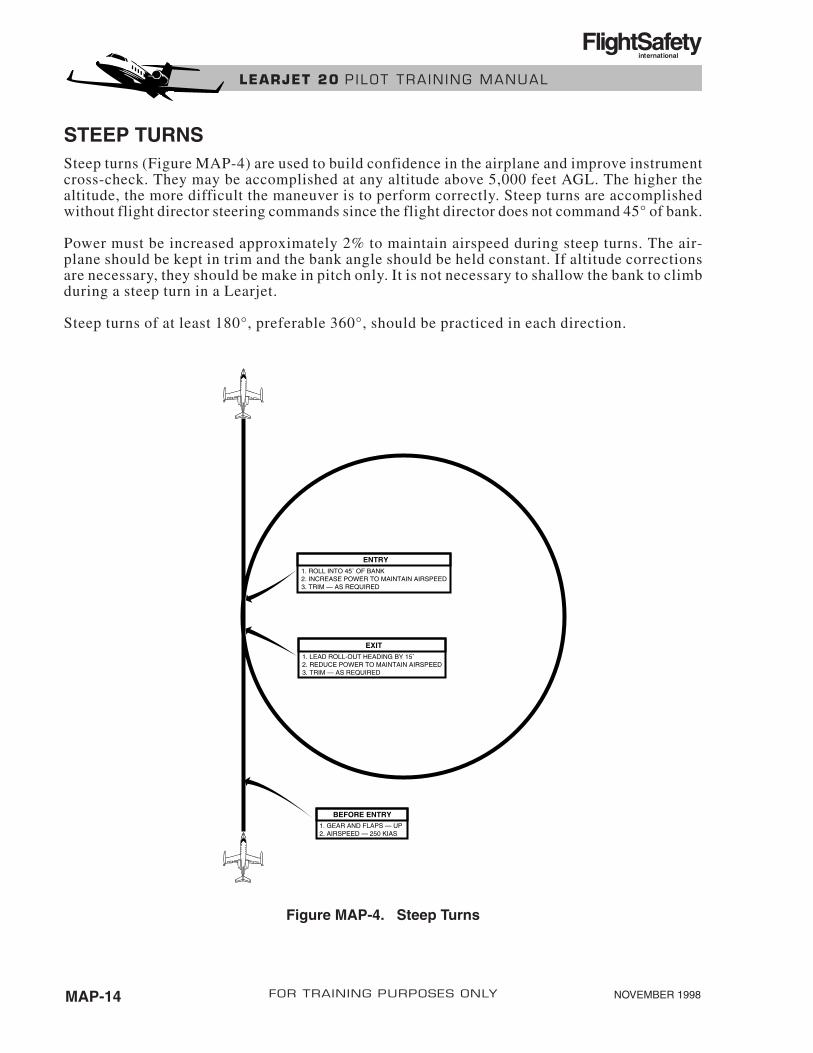
STEEP TURNSSteep turns (Figure MAP-4) are used to build confidence in the airplane and improve instrumentcross-check. They may be accomplished at any altitude above 5,000 feet AGL. The higher thealtitude, the more difficult the maneuver is to perform correctly. Steep turns are accomplishedwithout flight director steering commands since the flight director does not command 45° of bank.
Power must be increased approximately 2% to maintain airspeed during steep turns. The air-plane should be kept in trim and the bank angle should be held constant. If altitude correctionsare necessary, they should be make in pitch only. It is not necessary to shallow the bank to climbduring a steep turn in a Learjet.
Steep turns of at least 180°, preferable 360°, should be practiced in each direction.
NOVEMBER 1998MAP-14 FOR TRAINING PURPOSES ONLY
LEARJET 20 P ILOT TRA IN ING MANUAL
FlightSafetyinternational
ENTRY1. ROLL INTO 45˚ OF BANK2. INCREASE POWER TO MAINTAIN AIRSPEED3. TRIM — AS REQUIRED
EXIT1. LEAD ROLL-OUT HEADING BY 15˚2. REDUCE POWER TO MAINTAIN AIRSPEED3. TRIM — AS REQUIRED
1. GEAR AND FLAPS — UP2. AIRSPEED — 250 KIAS
BEFORE ENTRY
Figure MAP-4. Steep Turns

SLOW FLIGHTSlow flight is used to develop the pilot’s sense of feel for the airplane’s low-speed handling char-acteristics and improve the pilot’s coordination and instrument cross-check. Slow flight is ac-complished in the clean, takeoff, and landing configurations (Figures MAP-5, MAP-6 andMAP-7), and is normally accomplished between 10,000 and 15,000 feet MSL. Slow flightshould not be accomplished below 5,000 AGL.
Slow flight may be practiced while maintaining a constant altitude and heading or while main-taining a constant altitude and making turns to preselected headings. Slow flight may also bepracticed while making constant rate climbs and descents to preselected altitude. Slow flightpractice may be terminated by a recovery to normal cruise or an approach to stall.
NOVEMBER 1998 MAP-15FOR TRAINING PURPOSES ONLY
LEARJET 20 P ILOT TRA IN ING MANUAL
FlightSafetyinternational
OPTIONAL1. 15˚ BANK TURNS TO PRESELECTED HEADINGS2. CONSTANT RATE CLIMBS AND DESCENTS
DURING SLOW FLIGHT1. MAINTAIN ALTITUDE AND HEADING
ENTRY1. GEAR AND FLAPS — UP2. AIRSPEED — VREF + 20 KT3. ALTITUDE — 10,000 TO 15,000 FEET
Figure MAP-5. Slow Flight—Clean Configuration

NOVEMBER 1998MAP-16 FOR TRAINING PURPOSES ONLY
LEARJET 20 P ILOT TRA IN ING MANUAL
FlightSafetyinternational
OPTIONAL1. 15˚ BANK TURNS TO PRESELECTED HEADINGS2. CONSTANT RATE CLIMBS AND DESCENTS
DURING SLOW FLIGHT1. MAINTAIN ALTITUDE AND HEADING
ENTRY1. GEAR — UP OR DOWN2. FLAPS — 8° OR 20°3. AIRSPEED — VREF + 10 KT WITH FLAPS 8°, VREF WITH FLAPS 20°4. ALTITUDE — 10,000 TO 15,000 FEET
ENTRY1. GEAR — DOWN2. FLAPS — 40°3. AIRSPEED — VREF –10 KT 4. ALTITUDE — 10,000 TO 15,000 FEET
OPTIONAL1. 15˚ BANK TURNS TO PRESELECTED HEADINGS2. CONSTANT RATE CLIMBS AND DESCENTS
DURING SLOW FLIGHT1. MAINTAIN ALTITUDE AND HEADING
Figure MAP-6. Slow Flight—Takeoff Configuration
Figure MAP-7. Slow Flight—Landing Configuration
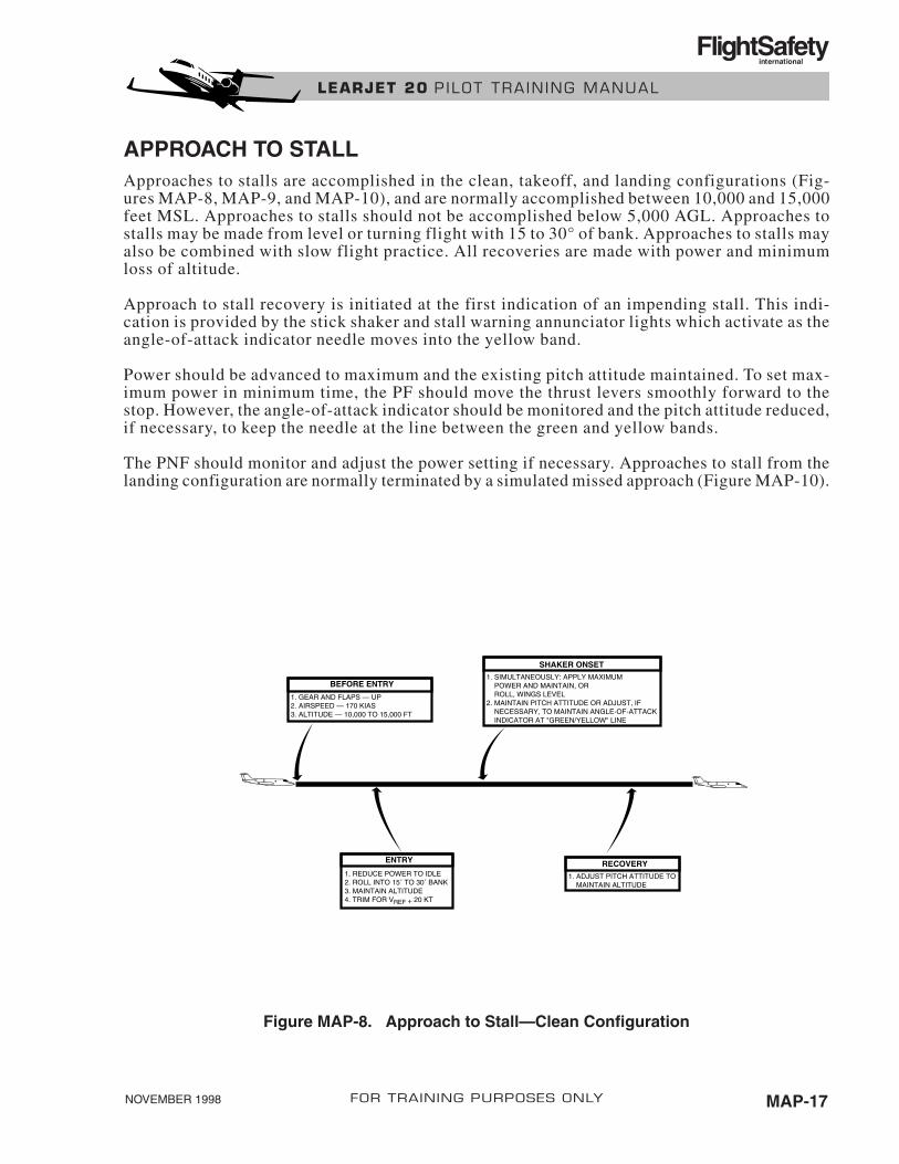
APPROACH TO STALLApproaches to stalls are accomplished in the clean, takeoff, and landing configurations (Fig-ures MAP-8, MAP-9, and MAP-10), and are normally accomplished between 10,000 and 15,000feet MSL. Approaches to stalls should not be accomplished below 5,000 AGL. Approaches tostalls may be made from level or turning flight with 15 to 30° of bank. Approaches to stalls mayalso be combined with slow flight practice. All recoveries are made with power and minimumloss of altitude.
Approach to stall recovery is initiated at the first indication of an impending stall. This indi-cation is provided by the stick shaker and stall warning annunciator lights which activate as theangle-of-attack indicator needle moves into the yellow band.
Power should be advanced to maximum and the existing pitch attitude maintained. To set max-imum power in minimum time, the PF should move the thrust levers smoothly forward to thestop. However, the angle-of-attack indicator should be monitored and the pitch attitude reduced,if necessary, to keep the needle at the line between the green and yellow bands.
The PNF should monitor and adjust the power setting if necessary. Approaches to stall from thelanding configuration are normally terminated by a simulated missed approach (Figure MAP-10).
NOVEMBER 1998 MAP-17FOR TRAINING PURPOSES ONLY
LEARJET 20 P ILOT TRA IN ING MANUAL
FlightSafetyinternational
RECOVERY1. ADJUST PITCH ATTITUDE TO MAINTAIN ALTITUDE
SHAKER ONSET1. SIMULTANEOUSLY: APPLY MAXIMUM POWER AND MAINTAIN, OR ROLL, WINGS LEVEL2. MAINTAIN PITCH ATTITUDE OR ADJUST, IF NECESSARY, TO MAINTAIN ANGLE-OF-ATTACK INDICATOR AT "GREEN/YELLOW" LINE
ENTRY
1. REDUCE POWER TO IDLE2. ROLL INTO 15˚ TO 30˚ BANK3. MAINTAIN ALTITUDE4. TRIM FOR VREF + 20 KT
BEFORE ENTRY
1. GEAR AND FLAPS — UP2. AIRSPEED — 170 KIAS3. ALTITUDE — 10,000 TO 15,000 FT
Figure MAP-8. Approach to Stall—Clean Configuration

NOVEMBER 1998MAP-18 FOR TRAINING PURPOSES ONLY
LEARJET 20 P ILOT TRA IN ING MANUAL
FlightSafetyinternational
RECOVERY1. ADJUST PITCH ATTITUDE TO MAINTAIN ALTITUDE
SHAKER ONSET1. SIMULTANEOUSLY: APPLY MAXIMUM POWER AND MAINTAIN, OR ROLL, WINGS LEVEL2. MAINTAIN PITCH ATTITUDE OR ADJUST, IF NECESSARY, TO MAINTAIN ANGLE OF ATTACK INDICATOR AT "GREEN/YELLOW" LINE
ENTRY
1. REDUCE POWER TO IDLE2. ROLL INTO 15˚ TO 30˚ BANK3. MAINTAIN ALTITUDE4. TRIM FOR VREF
BEFORE ENTRY
1. GEAR UP OR DOWN2. FLAPS 8° OR 20°3. AIRSPEEDVREF + 30 KT 4. ALTITUDE — 10,000 TO 15,000 FT
POSITIVE RATE OF CLIMB1. GEAR — UP2. CLIMB TO/MAINTAIN ASSIGNED ALTITUDE
SHAKER ONSET1. SIMULTANEOUSLY: APPLY MAXIMUM POWER AND MAINTAIN, OR ROLL, WINGS LEVEL2. MAINTAIN PITCH ATTITUDE OR ADJUST, IF NECESSARY, TO MAINTAIN ANGLE OF ATTACK INDICATOR AT "GREEN/YELLOW" LINE
BEFORE ENTRY1. GEAR — DOWN2. FLAPS — 40˚3. AIRSPEED — VREF + 10 KT4. ALTITUDE — 10,000 TO 15,000 FT AGL
ENTRY
1. REDUCE POWER TO ESTABLISH A ONE KNOT-PER-SECOND RATE OF DECELERATION2. ROLL INTO 15˚ TO 30˚ BANK3. MAINTAIN ALTITUDE4. TRIM FOR VREF - 10 KT
VREF + 30 KTS (MIN)
1. FLAPS — UP2. ACCELERATE TO CLIMB SPEED
VREF
1. FLAPS — 20˚
Figure MAP-9. Approach to Stall—Takeoff Configuration
Figure MAP-10. Approach to Stall—Landing Configuration

EMERGENCY DESCENTEmergency descents are accomplished in accordance with AFM procedures as shown in FigureMAP-11. The PF should accomplish the checklist memory items and allow the airplane to pitchdown to a 10 to 15° nosedown pitch attitude. This pitch attitude is maintained until the airplaneaccelerates to MMO/VLE. Then the pitch attitude is adjusted to maintain MMO/VLE.
After the emergency descent has been established, the crew should determine the desired level-off altitude.
NOVEMBER 1998 MAP-19FOR TRAINING PURPOSES ONLY
LEARJET 20 P ILOT TRA IN ING MANUAL
FlightSafetyinternational
ENTRY1. CREW OXYGEN MASKS — ON 2. POWER — IDLE3. AUTOPILOT — DISENGAGED4. SPOILERS — EXTENDED5. LANDING GEAR — DOWN (BELOW MMO/VLE)6. ESTABLISH APPROXIMATELY 10˚ TO 15˚ NOSE DOWN PITCH ATTITUDE
DESCENT1. MAINTAIN PITCH ATTITUDE UNTIL REACHING MMO/VLE2. ADJUST PITCH ATTITUDE TO MAINTAIN MMO/VLE LEVEL OFF
1. SPOILERS — RETRACTED2. GEAR — UP3. POWER — AS REQUIRED (IF GEAR WAS EXTENDED ABOVE VLO, GEAR SHOULD REMAIN DOWN, IF POSSIBLE)
Figure MAP-11. Emergency Descent

VISUAL TRAFFIC PATTERN, TWO ENGINESA two-engine visual traffic pattern is shown in Figure MAP-24. The airspeeds indicated on thediagram are minimums. Traffic pattern altitude for jet airplanes is normally 1,500 feet AGL.During gusty wind conditions, 1/2 the gust velocity should be added to VREF on final approach.If a crosswind exists, final approach should be flown with a drift correction angle (crab) to main-tain alignment with the runway centerline. Approaching touchdown, rudder should be appliedto align the airplane with the runway centerline and the upwind wing lowered with aileron toprevent drift.
VISUAL TRAFFIC PATTERN, SINGLE ENGINEA single-engine visual traffic pattern is flown exactly the same as a two-engine pattern exceptfor the flap setting on final approach. For a single-engine landing, final approach is flown theflaps 20° at VREF plus 10 knots minimum until the landing is assured. When the landing is as-sured, flaps should be extended to 40° and the airspeed slowed to VREF. Additionally, the PFmay elect to have the PNF remove 1/2 of the rudder trim on final approach, no lower than 500feet above the airport.
NOVEMBER 1998MAP-20 FOR TRAINING PURPOSES ONLY
LEARJET 20 P ILOT TRA IN ING MANUAL
FlightSafetyinternational
DOWNWIND LEG
ENTRY LEG
1. GEAR AND FLAPS — UP2. AIRSPEED — VREF PLUS 40 KT3. APPROACH CHECKLIST — COMPLETE
1. FLAPS — 8˚2. AIRSPEED — VREF PLUS 30 KT
MIDFIELD DOWNWIND1. FLAPS — 20˚2. GEAR — DOWN3. AIRSPEED — VREF PLUS 20 KT4. BEFORE LANDING CHECKLIST — COMPLETE TO FLAPS 40˚
FINAL APPROACH **1. FLAPS — 40˚2. AIRSPEED — VREF MINIMUM
** FOR SINGLE-ENGINE APPROACH, MAINTAIN FLAPS 20˚ AND VREF PLUS 10 KNOTS MINIMUM UNTIL LANDING IS ASSURED. WHEN LANDING IS ASSURED, FLAPS 40˚ AND VREF MINIMUM.
Figure MAP-12. Visual Traffic Pattern

FLAPS UP LANDINGThe corrected landing distance for a flaps up landing (Figure MAP-13) is determined by mul-tiplying the normal landing distance by 1.35. Considerations should be given to reducing theairplane’s weight, if possible, to lower the landing speed and reduce landing distance, if the avail-able runway length is marginal.
The yaw damper should be disengaged prior to landing on all models of 20’s.
To avoid excessive floating during the landing flare, the PF should establish the landing attitudeas power is reduced to idle, maintain the attitude and allow the airplane to touch down.The useof the drag chute, or thrust reversers, (if installed) is recommended during a flaps up landing.
NOVEMBER 1998 MAP-21FOR TRAINING PURPOSES ONLY
LEARJET 20 P ILOT TRA IN ING MANUAL
FlightSafetyinternational
ENTRY LEG1. GEAR AND FLAPS — UP2. AIRSPEED — VREF PLUS 40 KT3. APPROACH CHECKLIST — COMPLETE
MIDFIELD DOWNWIND1. GEAR — DOWN2. BEFORE LANDING CHECKLIST3. MAINTAIN VREF PLUS 40 KT
FINAL APPROACH1. AIRSPEED VREF PLUS 30 KT MINIMUM2. YAW DAMPER — DISENGAGED BEFORE TOUCHDOWN
Figure MAP-13. Flaps Up Landing

PRECISION INSTRUMENT APPROACHA typical, precision instrument approach is shown in Figure MAP-14. All accepted instru-ment flying procedures and techniques should be used while making instrument approaches inthe Learjet.
Two-engine, precision approaches should be flown with a stabilized airspeed and configura-tion from the final approach fix (FAF) inbound. Single-engine, precision approaches should beflown with flaps 20° at VREF plus 10 knots minimum from the FAF inbound until the landingis assured, then flaps 40° and VREF minimum.
NOVEMBER 1998MAP-22 FOR TRAINING PURPOSES ONLY
LEARJET 20 P ILOT TRA IN ING MANUAL
FlightSafetyinternational
APPROACHING INITIAL APPROACH FIX (IAF)1. GEAR AND FLAPS — UP2. AIRSPEED — VREF + 40 KT MINIMUM3. APPROACH CHECKLIST — COMPLETE
IAF OUTBOUND *1. FLAPS — 8˚2. AIRSPEED — VREF + 30 KT MINIMUM3. DESCEND, IF REQUIRED
ON COURSE INBOUND
1. FLAPS — 20˚2. GEAR — DOWN (3-5 MILES PRIOR TO FAF)3. AIRSPEED — VREF + 20 KT 4. BEFORE LANDING CHECKLIST — COMPLETE TO FLAPS 40˚
FINAL APPROACH FIX **1. FLAPS — 40˚2. AIRSPEED — VREF MINIMUM
* FOR A STRAIGHT-IN APPROACH, COMPLETE APPROACH AND BEFORE LANDING CHECKLISTS TO FLAPS 40˚ BEFORE REACHING THE FINAL APPROACH FIX.
** FOR SINGLE-ENGINE APPROACH, MAINTAIN FLAPS 20˚ AND VREF + 10 KT MINIMUM UNTIL LANDING IS ASSURED. WHEN LANDING IS ASSURED, FLAPS 40˚ AND VREF MINIMUM.
Figure MAP-14. Precision Instrument Approach

NONPRECISION INSTRUMENT APPROACHA typical, nonprecision instrument approach is shown in Figure MAP-15. All accepted instru-ment flying procedures and techniques should be used while making instrument approaches inthe Learjet.
Two-engine, nonprecision approaches should be flown with a stabilized airspeed and configu-ration from the final approach fix (FAF) inbound. Single-engine, nonprecision approachesshould be flown with flaps 20° at VREF plus 10 knots minimum from the FAF inbound until thelanding is assured, then flaps 40° and VREF minimum.
NOVEMBER 1998 MAP-23FOR TRAINING PURPOSES ONLY
LEARJET 20 P ILOT TRA IN ING MANUAL
FlightSafetyinternational
APPROACHING INITIAL APPROACH FIX (IAF)
1. GEAR AND FLAPS — UP2. AIRSPEED — VREF + 40 KT (MIN)3. APPROACH CHECKLIST — COMPLETE
IAF OUTBOUND *
1. FLAPS — 8˚2. AIRSPEED — VREF + 30 KT (MIN) 3. DESCEND — AS REQUIRED
FINAL APPROACH FIX **1. FLAPS — 40˚2. AIRSPEED — VREF MINIMUM
* FOR A STRAIGHT-IN APPROACH, COMPLETE APPROACH AND BEFORE LANDING CHECKLISTS TO FLAPS 40˚ BEFORE REACHING THE FINAL APPROACH FIX.
** FOR SINGLE-ENGINE APPROACH, MAINTAIN FLAPS 20˚ AND VREF PLUS 10 KNOTS MINIMUM UNTIL LANDING IS ASSURED. WHEN LANDING IS ASSURED, FLAPS 40˚ AND VREF MINIMUM.
ON COURSE INBOUND1. FLAPS — 20˚2. GEAR — DOWN (3-5 MILES PRIOR TO FAF)3. AIRSPEED — VREF + 20 KT4. BEFORE LANDING CHECKLIST — COMPLETE TO FLAPS 40˚
Figure MAP-15. Nonprecision Instrument Approach

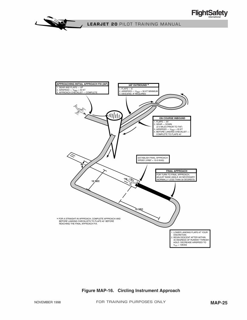
CIRCLING INSTRUMENT APPROACHAny instrument approach that requires a heading change of 30° or more to line up with the land-ing runway is a circling approach. An identifiable part of the airport must be distinctly visibleto the pilot during the circling approach, unless the inability to see an identifiable part of theairport results only from a normal bank of the airplane. The circling MDA and weather minimato be used are those for the runway to which the approach is flown.
The Learjet is an approach category C airplane. However, category D minimums should be usedif the airplane will be maneuvered at speeds over 141 knots (the minimum for category D air-planes) during the circling approach.
There are two types of circling approaches. The first type of circling approach positions the air-plane within 90°, or less, of the runway heading on a base leg for landing. With two engines,this type of approach is normally flown with the gear down and 20° of flaps at VREF plus 20knots minimum from the FAF inbound. When landing is assured, extend flaps to 40°. Airspeedmay be reduced to VREF minimum.
The second type of circling approach (Figure MAP-16) requires a heading change of more than90° to line up with the landing runway. With two engines, this type of approach is normally flownwith the gear down and 20° of flaps at VREF plus 20 knots minimum from the FAF inbound. Onfinal approach, flaps should be extended to 40° and airspeed reduced to VREF minimum.
All single-engine circling approaches should be flown with 20° of flaps at VREF + 20 knots fromthe FAF inbound. When landing is assured, flaps should be extended to 40° and airspeed re-duced to VREF minimum.
NOVEMBER 1998MAP-24 FOR TRAINING PURPOSES ONLY
LEARJET 20 P ILOT TRA IN ING MANUAL
FlightSafetyinternational
NOVEMBER 1998 MAP-25FOR TRAINING PURPOSES ONLY
LEARJET 20 P ILOT TRA IN ING MANUAL
FlightSafetyinternational
APPROACHING INITIAL APPROACH FIX (IAF)1. GEAR AND FLAPS — UP2. AIRSPEED — VREF + 40 KT3. APPROACH CHECKLIST — COMPLETE
IAF OUTBOUND *1. FLAPS — 8˚2. AIRSPEED — VREF + 30 KT MINIMUM3. DESCEND, IF REQUIRED
FINAL APPROACHFOR TURN TO FINAL APPROACH,ADJUST BANK ANGLE AS NECESSARY(NORMALLY LESS THAN 30 DEGREES)
ESTABLISH FINAL APPROACHSPEED (VREF + 10-0 KIAS)
1. LOWER LANDING FLAPS AT YOUR DISCRETION.2. BEGIN DESCENT AFTER WITHIN 45 DEGREES OF RUNWAY THRESH- HOLD. DECREASE AIRSPEED TO VREF + 10KIAS
ON COURSE INBOUND
15 SEC
15 SEC
90˚
1. FLAPS — 20˚2. GEAR — DOWN (3-5 MILES PRIOR TO FAF)3. AIRSPEED — VREF + 20 KT4. BEFORE LANDING CHECKLIST — COMPLETE TO FLAPS 40˚
* FOR A STRAIGHT-IN APPROACH, COMPLETE APPROACH AND BEFORE LANDING CHECKLISTS TO FLAPS 40˚ BEFORE REACHING THE FINAL APPROACH FIX.
Figure MAP-16. Circling Instrument Approach
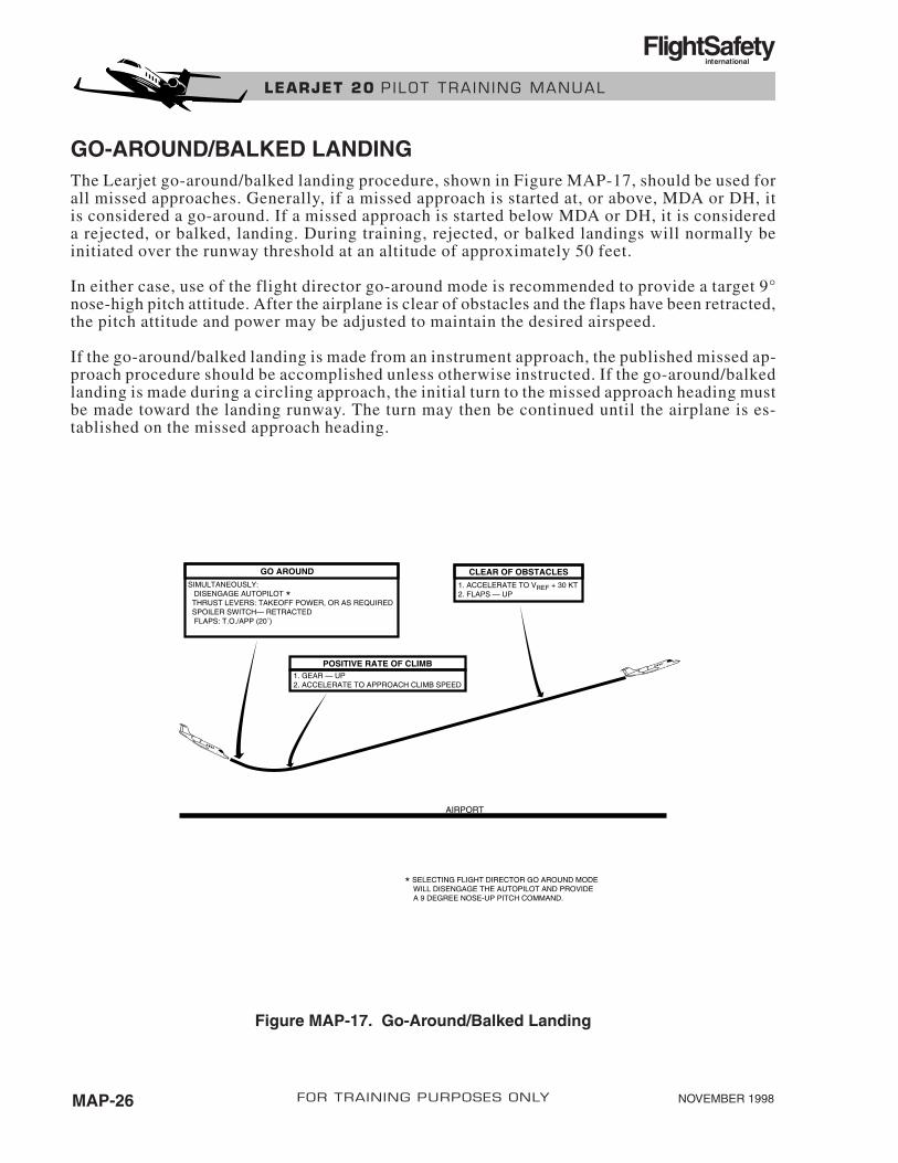
GO-AROUND/BALKED LANDINGThe Learjet go-around/balked landing procedure, shown in Figure MAP-17, should be used forall missed approaches. Generally, if a missed approach is started at, or above, MDA or DH, itis considered a go-around. If a missed approach is started below MDA or DH, it is considereda rejected, or balked, landing. During training, rejected, or balked landings will normally beinitiated over the runway threshold at an altitude of approximately 50 feet.
In either case, use of the flight director go-around mode is recommended to provide a target 9°nose-high pitch attitude. After the airplane is clear of obstacles and the flaps have been retracted,the pitch attitude and power may be adjusted to maintain the desired airspeed.
If the go-around/balked landing is made from an instrument approach, the published missed ap-proach procedure should be accomplished unless otherwise instructed. If the go-around/balkedlanding is made during a circling approach, the initial turn to the missed approach heading mustbe made toward the landing runway. The turn may then be continued until the airplane is es-tablished on the missed approach heading.
NOVEMBER 1998MAP-26 FOR TRAINING PURPOSES ONLY
LEARJET 20 P ILOT TRA IN ING MANUAL
FlightSafetyinternational
AIRPORT
GO AROUNDSIMULTANEOUSLY: DISENGAGE AUTOPILOT * THRUST LEVERS: TAKEOFF POWER, OR AS REQUIRED SPOILER SWITCH— RETRACTED FLAPS: T.O./APP (20˚)
POSITIVE RATE OF CLIMB1. GEAR — UP2. ACCELERATE TO APPROACH CLIMB SPEED
CLEAR OF OBSTACLES1. ACCELERATE TO VREF + 30 KT2. FLAPS — UP
* SELECTING FLIGHT DIRECTOR GO AROUND MODE WILL DISENGAGE THE AUTOPILOT AND PROVIDE A 9 DEGREE NOSE-UP PITCH COMMAND.
Figure MAP-17. Go-Around/Balked Landing
SINGLE-ENGINE DRIFT DOWNThe single-engine drift down procedure is used to cover the greatest possible distance whiledescending to single-engine cruise altitude after an engine failure at high altitude.
As the note on the chart explains, the speed schedule depicted also approximates the best sin-gle-engine, rate-of-climb speed below the single-engine service ceiling. This speed schedule maythen also be used to climb to single-engine cruise altitude after an engine failure at low altitude.
NOVEMBER 1998 MAP-27FOR TRAINING PURPOSES ONLY
LEARJET 20 P ILOT TRA IN ING MANUAL
FlightSafetyinternational

NOVEMBER 1998 PER-i
PERFORMANCE
CONTENTS
Page
INTRODUCTION ............................................................................................................. PER-1
GENERAL......................................................................................................................... PER-1
DEFINITIONS .................................................................................................................. PER-2
TAKEOFF PERFORMANCE ........................................................................................... PER-6
THRUST.......................................................................................................................... PER-11
CLIMB, CRUISE, AND DESCENT PLANNING ......................................................... PER-11
APPROACH AND LANDING PERFORMANCE......................................................... PER-14
FOR TRAINING PURPOSES ONLY
LEARJET 20 P ILOT TRA IN ING MANUAL
FlightSafetyinternational
NOVEMBER 1998 PER-iii
ILLUSTRATIONS
Figure Title Page
PER-1 Takeoff Profile .................................................................................................... PER-5
PER-2 Sample Takeoff Worksheet................................................................................. PER-7
PER-3 Sample Operational Planning Form ................................................................. PER-12
PER-4 Sample Landing Worksheet.............................................................................. PER-14
TABLE
Figure Title Page
PER-1 Climb Configuration................................................................................................. PER-4
FOR TRAINING PURPOSES ONLY
LEARJET 20 P ILOT TRA IN ING MANUAL
FlightSafetyinternational

PERFORMANCE
INTRODUCTIONAirplane performance is affected by many variables in addition to the usual ones, suchas airplane weight, density altitude, runway length, etc. In the case of the Learjet 20 se-ries, performance is also affected by type of engine, type of wing, design, and type ofbrakes installed.
GENERALMost performance data for all approved operating conditions is provided in chart form in thePerformance section of the approved Airplane Flight Manual. Except for Models 23 and 24,climb, cruise, and descent data are provided in the Learjet Pilot’s Manual. Airplane performancedata is also provided in tabular form in the Pilot’s Manual and the aircrew checklist. However,the effects of wind, runway gradient, anti-skid-off, and anti-ice on conditions are not compen-sated for in the tabular data in the crew checklists or the Pilot’s Manual. Therefore, if any ofthe above are factors, the AFM charts should be used for flight planning.
Weight and balance data is presented in the Weight and Balance section of the AFM.
Assumed ConditionsThe performance data presented for each phase of operation is based on certain assumed con-ditions. Assumed conditions, along with the description of the corresponding charts, are givenin this chapter.
Standard ConditionsStandard conditions which apply to all performance calculations are:
• Ambient temperature and pressure altitude
• Winds
• Gross weight
• Runway gradients
• Anti-ice on or off
• Anti-skid on or off
• Flaps 8°, 10°, 20°, or 10° overspeed for takeoff and 40° for landing
NOVEMBER 1998 PER-1FOR TRAINING PURPOSES ONLY
LEARJET 20 P ILOT TRA IN ING MANUAL
FlightSafetyinternational

DEFINITIONSThe following contains the symbols and definitions which are used in the Performance sectionof the AFM.
SpeedsIAS Indicated Airspeed
Airspeed indicator reading (assumes zero instrument error)
VMCA Minimum Control Speed, AirThe minimum flight speed at which the airplane is controllable with 5° of banktoward the good engine when one engine suddenly becomes inoperative and theremaining engine is operating at takeoff thrust.
VMCG Minimum Control Speed, GroundThe minimum speed on the ground at which control can be maintained usingaerodynamic controls alone, when one engine suddenly becomes inoperativeand the remaining engine is operating at takeoff thrust.
V1 Critical Engine Failure SpeedThe speed at which, due to engine failure or other causes, the pilot may elect tostop or continue the takeoff. If engine failure occurs at V1, the distance to con-tinue the takeoff to 35 feet will not exceed the usable takeoff distance. The dis-tance to stop the airplane will not exceed the accelerate-stop distance. V1 mustnot be less than VMCG or greater than VR.
VR Rotation SpeedThe speed at which rotation is initiated during takeoff to attain takeoffperformance.
V2 Takeoff Safety SpeedThe actual speed at 35 feet above the runway surface as demonstrated in flightduring single-engine takeoff. V2 is maintained to 1,500 feet above the runwayor until clear of obstacle to produce the maximum climb gradient. V2 must notbe less than 1.2 times the stalling speed, less than 1.1 times VMCA, or lessthan VR plus an increment in speed attained prior to reaching 35 feet abovethe runway.
VSO The stalling speed in the landing configuration.
VS1 The stalling speed in the appropriate gear/flap configuration.
VREF Landing Approach SpeedThe airspeed equal to 1.3 VSO with the airplane in the landing configuration.
NOVEMBER 1998PER-2 FOR TRAINING PURPOSES ONLY
LEARJET 20 P ILOT TRA IN ING MANUAL
FlightSafetyinternational

DistancesAccelerate-Stop The horizontal distance traversed from brake release to the point atDistance which the airplane comes to a complete stop on a takeoff during
which the pilot elects to stop at V1. This distance is based on asmooth, dry, hard-surface runway.
Accelerate-Go The horizontal distance traversed from brake release to the point atDistance which the airplane attains a height of 35 feet above the runway
surface on a takeoff during which one engine fails at V1 and thepilot elects to continue.
Takeoff Field Distance presented in the takeoff distance charts and equal to theLength accelerate-stop distance or the accelerate-go distance, whichever
is greater.
MeteorologyISA International Standard Atmosphere
RAT Ram-Air TemperatureThe static air temperature corrected for full adiabatic compressionrise corresponding to the calibrated Mach number and multipliedby a recovery factor
Wind The wind velocities recorded as variables on the performancecharts are the headwind or tailwind components of the actual windat 20 feet above the runway surface.
Demonstrated Adequate control of the airplane during takeoff and landing was ac-Limited tually demonstrated. This value may or may not be limiting. See the
appropriate AFM.
MiscellaneousStatic The static position correction is applied to indicated airspeed orPosition altitude to eliminate the effect of static pressure source location onCorrection the instrument reading. Instrument error is assumed to be zero.
Takeoff Expressed in the Takeoff Weight limits charts as the maximumBrake gross weight at which an aborted takeoff can be initiated at V1 andEnergy Limit completed within the computed accelerate-stop distance, using
maximum braking effort.
Landing Expressed in the Landing Weight Limit charts as the maximumBrake gross weight at which the airplane can be brought to a full stop with-Energy Limit in the computed landing distance, using maximum braking effort.
NOVEMBER 1998 PER-3FOR TRAINING PURPOSES ONLY
LEARJET 20 P ILOT TRA IN ING MANUAL
FlightSafetyinternational

Runway Change in runway elevation per 100 feet of runway length. TheGradient values given are positive for uphill and negative for downhill
gradients.
Gradient The ratio of the change in height during a portion of the climb toof Climb the horizontal distance traversed in the same interval.
Gross The climb gradient that the airplane can actually achieve givenClimb Gradient ideal conditions.
Net Climb The gross climb gradient reduced by 0.8% during the takeoff phase.Gradient This conservatism is required by FAR 25 for terrain clearance deter
mination to account for variables encountered in service.
Climb Segments (In Order of Occurrence)First The first segment climb begins from the point at which the airplaneSegment becomes airborne and ends at the point at which the landing gear isClimb fully retracted. Refer to Table PER-1 for the applicable configura
tion. Gross climb gradient with one engine inoperative and the otherengine at takeoff thrust must be positive, without ground effect. This requirement is satisfied by compliance with the applicableTakeoff Weight Limits Chart.
Second The second segment begins at the end of gear retraction and continSegment ues to height above the runway of 1,500 feet and V2 speed. It isClimb noted that the second segment in Figure PER-1 is shown only to a
height of 400 feet. However, this is a minimum requirement and forsimplified flight planning, the Takeoff Flight Path charts shown inthe Flight Manual present the second segment required gradients tothe 1,500-foot point for obstacle clearance considerations.
Revision .01PER-4 FOR TRAINING PURPOSES ONLY
LEARJET 20 P ILOT TRA IN ING MANUAL
FlightSafetyinternational
TYPE OF NO. OF ENGINES THRUST FLAP GEARCLIMB OPERATING SETTING POSITION
First Segment 1 Takeoff Takeoff Down
Second Segment 1 Takeoff Takeoff Up
Final Segment 1 Max cont Up Up
Enroute 1 Max cont Up Up
Approach 1 Takeoff 20° Up
Landing 2 Takeoff Dn-40° Down
Table PER-1. CLIMB CONFIGURATIONS

NOVEMBER 1998 PER-5FOR TRAINING PURPOSES ONLY
LEARJET 20 P ILOT TRA IN ING MANUAL
FlightSafetyinternational
SE
CO
ND
S
EG
ME
NT
FIN
AL
SE
GM
EN
T
EN
RO
UT
EC
LIM
B
1,50
0 F
T
CLE
AR
OF
OB
STA
CLE
(400
FT
MIN
IMU
M)
OB
STA
CLE
1,50
0 F
T A
BO
VE
RU
NW
AY
ALT
ITU
DE
24,0
00 F
TD
ISTA
NC
E F
RO
MR
EF
ZE
RO
GE
AR
UP
FIR
ST
SE
GM
EN
T
35 F
T
RE
FE
RE
NC
EZ
ER
O LIF
TO
FF
BR
AK
ER
ELE
AS
E 3,40
0 F
TTA
KE
OF
F D
ISTA
NC
E
3,90
0 F
TR
UN
WA
YR
EM
AIN
ING
20,1
00 F
T
7,30
0 F
TR
UN
WA
Y L
EN
GT
H
Fig
ure
PE
R-1
. T
akeo
ff P
rofi
le
Final Final segment climb begins t the end of the second segment andSegment ends at a height of at least 1,500 feet AGL. The gross climb gradClimb ient must be at least 1.2% with one engine not operating and the
other engine at maximum continuous thrust. This requirement is sat-tisfied by compliance with the applicable Takeoff Weight Limitschart. Airspeed for this segment is 1.25 VS. The final segment climbgradients are presented for pilot’s reference and are not used in thetakeoff path calculation.
Enroute Enroute climb is a climb with flaps up, landing gear retracted, andClimb maximum continuous thrust on one engine. There is no minimum re
quirement for enroute climb gradients. The enroute net climb gra-dients are presented for pilot’s reference. Velocity is presented inthe Enroute Climb Speed Schedule chart.
Approach This climb is made from a missed or aborted approach. With the airClimb plane in the appropriate configuration (flaps 20°, gear up, and take-
off thrust on one engine), the gross climb gradient must be at least2.1%. This requirement is satisfied by compliance with the LandingWeight Limits chart. Airspeed for this maneuver is 1.3 VS1.
Landing This climb is made from an aborted landing. When the airplane is inClimb the landing climb configuration (flaps and gear down, takeoff thrust
on both engines), the gross climb gradient must be at least 3.2%.This requirement is satisfied by compliance with the LandingWeight Limits chart. Landing climb airspeed is 1.3 VS0.
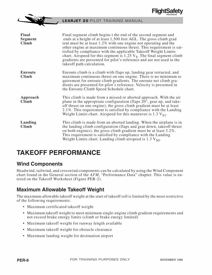
TAKEOFF PERFORMANCE
Wind ComponentsHeadwind, tailwind, and crosswind components can be calculated by using the Wind Componentchart found in the General section of the AFM, “Performance Data” chapter. This value is en-tered on the Takeoff Worksheet (Figure PER-2).
Maximum Allowable Takeoff WeightThe maximum allowable takeoff weight at the start of takeoff roll is limited by the most restrictiveof the following requirements:
• Maximum certificated takeoff weight
• Maximum takeoff weight to meet minimum single-engine climb gradient requirements andnot exceed brake energy limits (climb or brake energy limited)
• Maximum takeoff weight for runway length available
• Maximum takeoff weight for obstacle clearance
• Maximum landing weight for destination airport
NOVEMBER 1998PER-6 FOR TRAINING PURPOSES ONLY
LEARJET 20 P ILOT TRA IN ING MANUAL
FlightSafetyinternational

TAKEOFF WORKSHEET
TEMP RWY LENGTH WEATHER
PA RWY GRAD ANTI-ICE
WIND ANTI-SKID
TAKEOFF WEIGHT LIMITS (POUNDS)
OBSTACLE CLEARANCE
OBSTACLE HEIGHT OBSTACLE DISTANCE FROMEND OF RUNWAY
*Distance from Reference Zero = Obstacle distance from end of runway + runway length - takeoff distance
FLAPSFLAPS
NOVEMBER 1998 PER-7FOR TRAINING PURPOSES ONLY
LEARJET 20 P ILOT TRA IN ING MANUAL
FlightSafetyinternational
Figure PER-2. Sample Takeoff Worksheet
CERTIFI CLIMB BRAKE TAKEOFF PLANNED TAKEOFF
CATED WT ENERGY WT FOR TAKEOFF DISTANCE
TAKEOFF WT RWY WT
WT LENGTH
EPR V1 VR V2
FLAPSFLAPS
GROSS WT TO DIST DIST FROM CLIMB GRAD CLIMB GRAD
(from above REF ZERO* REQUIRED POSSIBLE
or estimate)
FLAPSFLAPS
FLAPSFLAPS

Maximum Certificated Takeoff WeightMaximum certificated takeoff weights vary according to model—refer to the appropriate AFMfor the airplane weight.
Maximum Takeoff Weight (Climb or Brake Energy Limited)The Takeoff Weight Limit charts found in the Takeoff section of the AFM, “Performance Data”chapter, provide the maximum takeoff weight for a given temperature and pressure altitude (PA). Thiswill allow the airplane to meet minimum climb gradients if an engine fails at or after V1 speed andtakeoff is continued or braking to a full stop without exceeding brake energy limits if takeoff is rejectedat or below V1 speed. There are separate charts for takeoff with flaps at 8°, 10°, 20°, and 10°overspeed depending on type of wing and for Century III wings with and without Softflite (AMK 83-5or AAK 79-10).
Maximum Takeoff Weight for Runway AvailableIf the computed takeoff field length determined from the AFM Takeoff Distance chart is lessthan the runway length available, takeoff weight is not limited due to runway length. However,if the computed takeoff distance exceeds the runway length available, the airplane gross weightmust be reduced or takeoff delayed until atmospheric conditions change (cooler temperature,increased wind velocity, or wind shift to a longer runway, etc.).
The maximum takeoff weight, limited by available runway, can be determined by entering the TakeoffDistance chart on the right side with the runway length available and working backward to the GrossWeight section. Read the gross weight directly below the point at which these two entries intersect inthe Gross Weight section. This is the gross weight that will permit takeoff within the runway lengthavailable.
Maximum Takeoff Weight for Obstacle ClearanceTakeoff flight path charts are provided in the Takeoff section of the AFM, “Performance Data”chapter, to enable the operator to determine the net climb gradient required to clear an obsta-cle in the takeoff flight path. Additionally, climb gradient charts are provided in the same sec-tion which enables the operator to determine the net climb gradient possible (one engineinoperative) for airplane gross weight and existing atmospheric conditions.
In the event that the computed climb gradient required exceeds the single-engine climb gradi-ent possible, the airplane takeoff gross weight must be reduced or takeoff delayed until atmo-spheric conditions change to allow the computed climb gradient possible to exceed the climbgradient required.
Reducing the airplane’s gross weight increases climb gradient possible. At the same time, climbgradient required also decreases because the takeoff distance is reduced, providing more dis-tance from the obstacle. Therefore, an interpolative process is required to find the exact mini-mum gradient and maximum weight for obstacle clearance. This process will be describedfurther in the example.
Revision .01PER-8 FOR TRAINING PURPOSES ONLY
LEARJET 20 P ILOT TRA IN ING MANUAL
FlightSafetyinternational
Takeoff Flight PathTakeoff flight path charts are provided for 8°, 10°, and 20° flap settings.
Both close-in and distant charts are provided to determine the climb gradient requirements forobstacle clearance from Reference Zero.
The origin for each climb gradient line is Reference Zero (Figure PER-1). This is a point 35feet above the runway at the computed takeoff distance. The climb gradient lines are dividedinto first and second segments. For purposes of flight path calculations, the second segment ex-tends to 1,500 feet AGl, and the final segment flight path is not considered. Dee Howard MarkII and XR performance charts do not show first segment climb performance.
Horizontal distance from Reference Zero is calculated by adding the runway remaining beyondReference Zero to the distance between the end of the runway and the obstacle.
In addition to finding the climb gradient required, note whether the obstacle falls within the firstor second segment. If the intersect point is to the left of the Gear Down—Gear Up line, the ob-stacle is in the first segment. If the intersect point is to the right of the line, the obstacle is in thesecond segment. It is important to note this in order to select the proper climb gradient chart (firstsegment or second segment) to find the climb gradient possible for this example. Note also thatthe climb gradient lines on the chart have a different value in the first and second segments.
Climb GradientsFirst, Second, and Final Segment Climb Gradient charts are provided to determine the climb-gradient possible for airplane gross weight and atmospheric conditions. First and Second ClimbGradient charts (Flaps 8°, 10°, or 20°) are used in conjunction with the Takeoff Flight Path charts,which show required net gradients for obstacle clearance. The Final Segment Climb Gradientchart is provided for reference only.
As previously mentioned reducing takeoff gross weight reduces climb gradient required and in-creases climb gradient possible.
As a result, finding the maximum takeoff gross weight that allows obstacle clearance becomesan interpolative process. A suggested method for accomplishing this is to average the climb gra-dient possible and climb gradient required and enter the Climb Gradient chart on the right withthis value.
Takeoff Speeds (V1, VR and V2)These speeds are found in the Critical Engine Failure Speed (V1), Rotation Speed (VR), and TakeoffSafety Speed (V2) charts in the AFM. Separate charts are provided for 8°, 10°, 20°, and 10° over-speed flap settings. For a review of theses abbreviations (V1, VR, and V2), see Definitions inthis chapter.
Revision .01 PER-9FOR TRAINING PURPOSES ONLY
LEARJET 20 P ILOT TRA IN ING MANUAL
FlightSafetyinternational

Critical Engine Failure Speed (V1)Data provided by the Critical Engine Failure Speed chart is based on three assumptions: take-off power is set before brake release, the takeoff runway is dry, hard, and smooth, and tires andbrakes are operating at normal efficiency.
These assumptions are of particular importance anytime the computed takeoff distance ap-proaches the available runway length. When these assumed conditions are not met, there is noassurance of being able to stop the airplane within the computed takeoff distance if takeoff isrejected at V1 speed.
Rotation Speed (VR)Rotation speed is affected only by airplane gross weight.
Takeoff Safety Speed (V2)Takeoff safety speed (V2), like rotation speed, is affected only by airplane gross weight.
Takeoff Field LengthTakeoff field length data assumes a smooth, dry hard-surface runway.
The takeoff distances computed from the takeoff distance charts in the AFM are accurate onlywhen the following procedures are used:
1. Set takeoff EPR prior to brake release.
2. Rotate to approximately 9° noseup at VR.
3. For engine failure after V1, accelerate to V2 after liftoff and then adjust pitch, as required,to maintain V2.
The pilot must use these procedures whenever the computed takeoff distance is at or near theactual runway length. Otherwise, the actual takeoff distance may exceed the chart value andrunway length available. Takeoff power settings are discussed later under Takeoff Thrust inthis chapter.
The Takeoff field length data presented in the AFM is governed by the accelerate-stop or theengine-out accelerate-go distance, whichever is greater.
The Takeoff Distance charts in the AFM are presented for 8°, 10°, 20°, or 10° overspeed flapssettings. These charts may be used to determine either of the following:
1. Runway length required for a given airplane weight.
2. Maximum airplane takeoff weight corresponding to a specific runway length. The pro-cess for finding the maximum airplane weight for a given runway length was previouslydescribed in this chapter under Maximum Takeoff Weight for Runway Available.
Revision .01PER-10 FOR TRAINING PURPOSES ONLY
LEARJET 20 P ILOT TRA IN ING MANUAL
FlightSafetyinternational
THRUST
Takeoff ThrustTakeoff performance is based on the assumption that the engines will be operating at a specificengine pressure ratio for a given temperature and pressure altitude (takeoff power). Takeoff powermust be maintained from brake release to 35 feet above the runway or until obstacle clearancein the event of engine failure on takeoff.
Takeoff from a standing start with takeoff thrust set before brake release must be accomplishedwhen the computed takeoff distance is at or near actual runway length. Also takeoff from a stand-ing start must be accomplished to ensure computed obstacle clearance performance.
The more comfortable rolling takeoff may be accomplished when actual runway length is at least10% longer than computed takeoff distance, and obstacle clearance is not a factor. When take-off roll is initiated before setting takeoff power, ensure that takeoff thrust is established beforereaching the point at which the runway remaining equals the computed takeoff distance.
If EPR is below that specified in the Takeoff Power Setting charts for the existing temperatureand pressure altitude, airplane takeoff performance will not meet the takeoff performance spec-ified in the performance charts. If EPR is above computed takeoff power, airframe or enginelimits may be exceeded. Thus, it is necessary to compute takeoff power and adjust the powerlevers as necessary to set EPR equal to chart value. In addition, operation at a specific EPR shouldalways be within EGT and rpm limits.
NOTEDuring takeoff, EPR will decay approximately 0.015 from the initial static setting.
Maximum Climb ThrustThe climb performance data is predicated on adjusting thrust EPR after takeoff to the value foundin the Maximum Continuous Thrust (EPR) tables in the AFM.
The maximum continuous thrust (EPR) setting may be determined before takeoff using estimatedtemperature and altitude at start of climb. Since the Maximum Continuous Thrust (EPR) tableis based on ram-air temperature in degrees Celsius, the reported or estimated OAT must be con-verted to RAT before entering the chart.
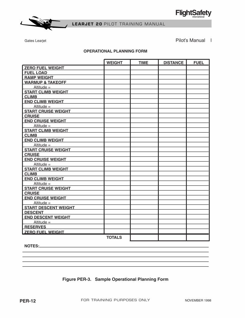
CLIMB, CRUISE, AND DESCENT PLANNINGFor those airplanes which have a Pilot’s Manual, an Operational Planning Form is providedin the Flight Planning Data section of that manual. See Figure PER-3 in this chapter for asample form.
NOVEMBER 1998 PER-11FOR TRAINING PURPOSES ONLY
LEARJET 20 P ILOT TRA IN ING MANUAL
FlightSafetyinternational
NOVEMBER 1998PER-12 FOR TRAINING PURPOSES ONLY
LEARJET 20 P ILOT TRA IN ING MANUAL
FlightSafetyinternational
Figure PER-3. Sample Operational Planning Form
Gates Learjet Pilot’s Manual l
OPERATIONAL PLANNING FORM
WEIGHT TIME DISTANCE FUEL ZERO FUEL WEIGHTFUEL LOADRAMP WEIGHTWARMUP & TAKEOFF
Altitude =START CLIMB WEIGHTCLIMBEND CLIMB WEIGHT
Altitude =START CRUISE WEIGHTCRUISEEND CRUISE WEIGHT
Altitude =START CLIMB WEIGHTCLIMBEND CLIMB WEIGHT
Altitude =START CRUISE WEIGHTCRUISEEND CRUISE WEIGHT
Altitude =START CLIMB WEIGHTCLIMBEND CLIMB WEIGHT
Altitude =START CRUISE WEIGHTCRUISEEND CRUISE WEIGHT
Altitude =START DESCENT WEIGHTDESCENTEND DESCENT WEIGHT
Altitude =RESERVESZERO FUEL WEIGHT
TOTALS
NOTES:
Climb PerformanceA set of climb performance tables is provided in the Pilot’s Manual to determine time, distance(no wind), and fuel required for climb from sea level. If climb is initiated at an altitude abovesea level, subtraction of performance values for the cruise altitude results in the time, distance,and fuel required for climb between two altitudes.
Each chart provides the climb performance data for a specific airplane gross weight at the startof the climb.
Cruise PerformanceCruise performance tables are provided in the airplane checklist or the Pilot’s Manual for normalcruise, high-speed cruise, and long-range cruise.
Normal CruiseNormal cruise tables provide fuel flows and true airspeed for constant 0.77 Mach cruise. Engine poweris adjusted to maintain the constant Mach as weight decreases. Enter the appropriate table for theaverage airplane gross weight for each cruise segment.
High-Speed CruiseHigh-speed cruise tables provide fuel flows, indicated Mach or airspeed, and the true airspeed for anMMO/VMO or VMAX at maximum continuous thrust. Enter the appropriate table for the averageairplane gross weight during each cruise segment.
Long-Range CruiseIn planning long-range cruise, the selected cruise altitude should provide the maximum air nauticalmiles per pound of fuel for a given airplane weight.
It can be seen from the chart that as airplane gross weight decreases, the altitude that providesbest fuel economy increases. Therefore, when planning for maximum range, the cruise portionof the flight should be divided into segments, with an appropriately higher cruise altitude plannedas airplane gross weight decreases. As a rough guide in planning for changes in cruise altitude,increase cruise altitude 1,000 feet for each 1,000-pound decrease in gross weight (fuel used).
Descent PerformanceDescent Performance Schedules are provided in the Pilot’s Manual to provide time, distance(no wind), and fuel used for descent to sea level. Subtraction of performance values for two al-titudes results in time, distance, and fuel required for descent between the two altitudes. Thedescent speed schedules presented at the bottom of the table should be followed to achieve thedesired results.
Fuel ReserveFAR Part 91 requires a fuel reserve (IFR conditions) of 45 minutes at destination or at the al-ternate airport if an alternate is required. Fuel reserve is computed at normal cruise speed. Theairplane checklist or Pilot’s Manual also contains a Holding Operations table which providesmaximum endurance holding speed and fuel flow for the airplane weight and pressure altitude.
Revision .01 PER-13FOR TRAINING PURPOSES ONLY
LEARJET 20 P ILOT TRA IN ING MANUAL
FlightSafetyinternational

APPROACH AND LANDING PERFORMANCEApproach and performance data are provided in chart form in the AFM Performance section andin tabular form in the Learjet Pilot’s Manual and Checklist. A sample Landing Worksheet isshown in Figure PER-4.
LANDING WORKSHEET
TEMP RWY LENGTH WEATHER
PA RWY GRAD ANTI-ICE
WIND ANTI-SKID
Maximum Allowable Landing WeightThe maximum allowable landing weight is limited by the most restrictive of the following re-quirements:
• Maximum certificated landing weight
• Maximum landing weight (approach climb or brake energy limited)
• Maximum landing weight for the runway length available
NOVEMBER 1998PER-14 FOR TRAINING PURPOSES ONLY
LEARJET 20 P ILOT TRA IN ING MANUAL
FlightSafetyinternational
CERTIFI- APPR BRAKE LANDING PLANNED LANDING
CATED CLIMB ENERGY WT FOR LANDING DISTANCE
LANDING WT WT RWY LENGTH WT
WT
VREF APPR CLIMBSPEED
Figure PER-4. Sample Landing Worksheet
Maximum Landing Weight (Approach Climb or Brake Energy Limited)The Landing Weight Limit charts (Approach Climb and Brake Energy Limited) provide a max-imum approach/landing weight which allows the airplane to meet a minimum climb gradient(single engine) in the event of missed approach or braking to a full stop without exceeding brakeenergy limits.
Maximum Landing Weight for Runway AvailableIf landing distance for existing gross weight is computed to be greater than the runway avail-able, the gross weight must be reduced before using that runway. Landing weight for runwaylength available may be determined by working through the Landing Distance chart backward.Use the same procedure as previously described for finding maximum takeoff gross weight fora given runway length.
This computation is made using the same method as that used to fund maximum takeoff weightfor runway available. Enter the Landing Distance chart on the right and work backward in thechart to the Gross Weight section and draw a light line through the Gross Weight section.
Now enter the chart on the left with temperature and pressure altitude and proceed to the GrossWeight section. The maximum landing weight for runway available is read directly below thepoint at which the two entries intersect in the Gross Weight section.
Landing DistanceThe landing distances computed from the Landing Distance chart can be achieved when the fol-lowing procedures are used:
1. Approach through the 50-foot point over the end of the runway at VREF with flaps andgear down, using a 21/2-3° glide slope.
2. After passing through the 50-foot point, progressively reduce thrust until thrust levers areat IDLE prior to touchdown.
3. After touchdown, extend spoilers immediately.
4. Apply wheel brakes as soon as practical and continue maximum braking action until theairplane stops.
5. After landing, move the control column full aft and maintain that position until the air-plane stops.
Pulling the control column aft will shift weight to the main wheels and improve braking effi-ciency. Pull the control column as far aft as possible but do not lift the nosewheel.
The Landing Distance chart is based upon smooth, dry, hard-surface runways. The landing fieldlength is equal to the horizontal distance from a point 50 feet above the runway surface to thepoint at which the airplane comes to a full stop on the runway.
NOVEMBER 1998 PER-15FOR TRAINING PURPOSES ONLY
LEARJET 20 P ILOT TRA IN ING MANUAL
FlightSafetyinternational
Those operators governed by FAR Part 91 determine landing distance from the Landing Distancechart. When the landing configuration speed is other than normal, the appropriate procedure inthe Emergency section of the AFM provides a factor to apply to the normal landing distance.
When the runway is other than dry, the following factors should also be applied to the LandingDistance chart:
Wet—apply a 1.4 factor to the computed landing distance.
Wet (in the process of freezing)—apply a factor of at least 1.7 to the computed landingdistance.
NOTEFor all operations, corrections to be applied to account for the presence of solid ice,snow, or slush are unknown.
Approach minimum maneuvering speeds are based on 1.3 times the airplane’s stall speed withidle thrust in applicable configuration and a 30-degree bank angle. Minimum maneuveringspeeds are as follows:
• No-flap configuration—VREF + 40 KIAS
• FLAPS 8° configuration—VREF + 30 KIAS
• FLAPS 20° configuration—VREF + 20 KIAS
• FLAPS 40° configuration—VREF + 10 KIAS
On final approach (with bank angle no more than 15°), 10 KIAS may be subtracted from theabove speeds.
Landing Approach Speed (VREF)VREF is determined from the Landing Approach Speed (VREF) chart in the AFM. Since VREFis determined strictly by airplane gross weight, VREF speeds listed in tabular form in the Pilot’sManual and Checklist may be used with equal accuracy.
Approach and Landing SpeedsSee Definitions in this chapter for a description of approach climb speed and landing climb speed.Like landing approach speed, VREF, approach, and landing climb are based strictly on airplaneweight. Checklist data may not be current. Confirm accuracy of tabulated data with the approvedAFM. Approach climb and landing climb speeds are provided on the same chart in the AFM.
Revision .01PER-16 FOR TRAINING PURPOSES ONLY
LEARJET 20 P ILOT TRA IN ING MANUAL
FlightSafetyinternational

WEIGHT AND BALANCE
CONTENTS
Page
GENERAL .......................................................................................................................... WB-1
WEIGHT AND BALANCE COMPUTATION .................................................................. WB-1
NOVEMBER 1998 WB-iFOR TRAINING PURPOSES ONLY
LEARJET 20 P ILOT TRA IN ING MANUAL
FlightSafetyinternational

ILLUSTRATIONS
Figure Title Page
WB-1 Basic Empty Weight Moment Sources (Weight and Balance Data) .................... WB-2
WB-2 Weight and Balance Schedule—Models 23 and 24 through 24F ........................ WB-3
WB-3 Weight and Balance Schedule—Models 25, 25B, and 25D ................................ WB-4
WB-4 Weight and Balance Schedule—Models 25C/F................................................... WB-5
WB-5 Airplane Equipment Configuration .................................................................... WB-6
NOVEMBER 1998 WB-iiiFOR TRAINING PURPOSES ONLY
LEARJET 20 P ILOT TRA IN ING MANUAL
FlightSafetyinternational

NOVEMBER 1998 WB-1FOR TRAINING PURPOSES ONLY
LEARJET 20 P ILOT TRA IN ING MANUAL
FlightSafetyinternational
WEIGHT AND BALANCE
GENERALThe airplane weight and load arrangement must be within limits of the applicable center-of-grav-ity (CG) at all times. Prior to each flight, the pilot must make certain that the airplane is loadedwithin the defined limits to ensure acceptable stability, control, performance, and structural loads.
Weight and balance data are supplied in the Weight ad Balance Data section of the AFM by themanufacturer when the airplane is delivered.
Before any weight and balance computations can be made, the basic empty weight and result-ing moment must be ascertained. This information is available from the Weight and Balancesection of the AFM (Figure WB-1). Any changes to the airplane that affect weight and balancemust be entered in the airplane records. It is advisable to check both pages to make certain thatthe weights and moments agree. The Weight and Balance Data section also contains all chartsand tables necessary for CG computations.
WEIGHT AND BALANCE COMPUTATIONSThe first step in computing weight and balance is to determine the basic empty weight and mo-ment from the Airplane Weighting Record in the AFM. However, if the airplane has been al-tered, determine the basic empty weight and moment from the Aircraft Records. The momentmay be listed as a seven-digit figure, as shown in Figure WB-1. In this case, the decimal pointmust be moved three digits to the left when entering the moment on the worksheet. This is be-cause all weight and balance charts and tables are based on moment per 1,000. This reduces thefigures in the numerical data to a more manageable size.
When the weight and balance worksheet has been filled in, the center of gravity can be deter-mined by using the graph, the chart, or by using the following formula:
Weight and balance computation worksheets for three model groupings are shown in FiguresWB-2 through WB-4.
Figure WB-5 shows two examples of airplane equipment needed for weight and balance com-putations. On the left is a typical portrayal of the 23 and 24 series Learjets. On the right is the25 series.
MomentWeight
X 1,000 - LEMAC
84.49 (MAC)X 100 = CG (% of MAC)
where LEMAC is210.04 inches forall 23 and 24 models and 360.02 inches forall 25 models
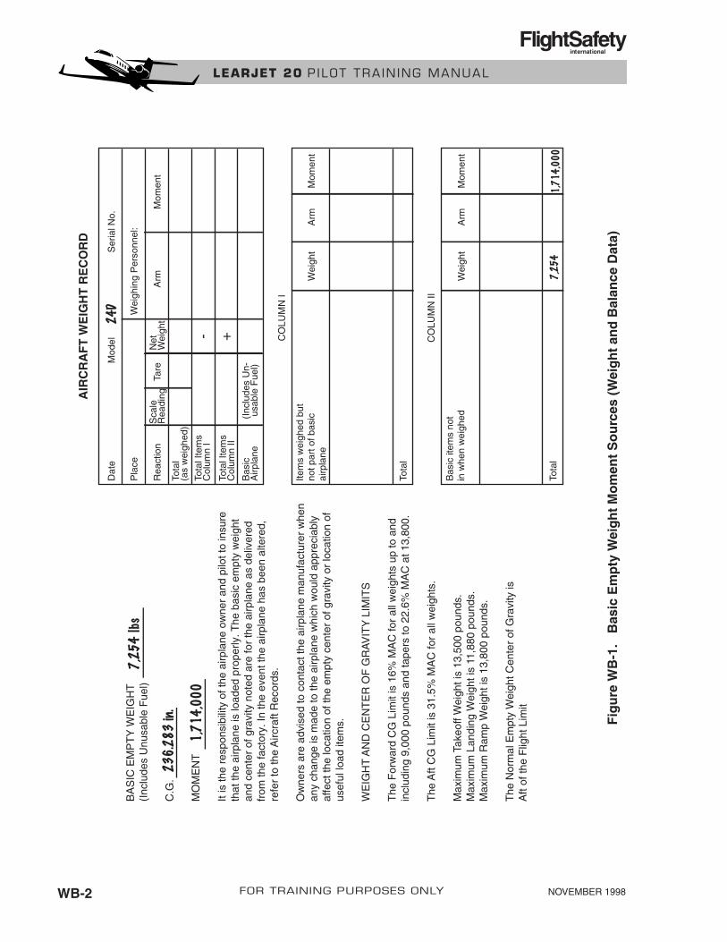
NOVEMBER 1998WB-2 FOR TRAINING PURPOSES ONLY
LEARJET 20 P ILOT TRA IN ING MANUAL
FlightSafetyinternational
AIR
CR
AF
T W
EIG
HT
RE
CO
RD
Dat
e
Pla
ce
Rea
ctio
nTa
reA
rmM
omen
t
Tota
l(a
s w
eigh
ed)
Sca
leR
eadi
ngN
etW
eigh
t
Tota
l Ite
ms
Col
umn
I
Tota
l Ite
ms
Col
umn
II
Bas
icA
irpla
ne(I
nclu
des
Un-
usa
ble
Fue
l)
Wei
ghin
g P
erso
nnel
:
Mod
elS
eria
l No.
- +
Tota
l
Item
s w
eigh
ed b
utno
t par
t of b
asic
airp
lane
Wei
ght
Arm
Mom
ent
Tota
l
Bas
ic it
ems
not
in w
hen
wei
ghed
Wei
ght
Arm
Mom
ent
CO
LUM
N I
CO
LUM
N II
BA
SIC
EM
PT
Y W
EIG
HT
(Inc
lude
s U
nusa
ble
Fue
l)
C.G
.
MO
ME
NT
It is
the
resp
onsi
bilit
y of
the
airp
lane
ow
ner
and
pilo
t to
insu
reth
at th
e ai
rpla
ne is
load
ed p
rope
rly. T
he b
asic
em
pty
wei
ght
and
cent
er o
f gra
vity
not
ed a
re fo
r th
e ai
rpla
ne a
s de
liver
edfr
om th
e fa
ctor
y. In
the
even
t the
airp
lane
has
bee
n al
tere
d,re
fer
to th
e A
ircra
ft R
ecor
ds.
Ow
ners
are
adv
ised
to c
onta
ct th
e ai
rpla
ne m
anuf
actu
rer
whe
nan
y ch
ange
is m
ade
to th
e ai
rpla
ne w
hich
wou
ld a
ppre
ciab
lyaf
fect
the
loca
tion
of th
e em
pty
cent
er o
f gra
vity
or
loca
tion
ofus
eful
load
item
s.
WE
IGH
T A
ND
CE
NT
ER
OF
GR
AV
ITY
LIM
ITS
The
For
war
d C
G L
imit
is 1
6% M
AC
for
all w
eigh
ts u
p to
and
incl
udin
g 9,
000
poun
ds a
nd ta
pers
to 2
2.6%
MA
C a
t 13,
800.
The
Aft
CG
Lim
it is
31.
5% M
AC
for
all w
eigh
ts.
Max
imum
Tak
eoff
Wei
ght i
s 13
,500
pou
nds.
Max
imum
Lan
ding
Wei
ght i
s 11
,880
pou
nds.
Max
imum
Ram
p W
eigh
t is
13,8
00 p
ound
s.
The
Nor
mal
Em
pty
Wei
ght C
ente
r of
Gra
vity
isA
ft of
the
Flig
ht L
imit
Fig
ure
WB
-1.
Bas
ic E
mp
ty W
eig
ht
Mo
men
t S
ou
rces
(W
eig
ht
and
Bal
ance
Dat
a)

LEARJET MODEL 23, 24, 24B, 24D, 24E, 24FWEIGHT AND BALANCE SCHEDULE
STATION QUANTITY WEIGHT MOMENT C.G.
Basic Empty Wt. xxxx xxxxxxxx xxxx
Crew 103 2Provisions 114 xxxx
xxxxProvision-Powder Rm. 144 xxxx
xxxxWash Basin 135 xxxx
xxxxChemical Toilet 127 xxxx
xxxxOperating Weight xxxx xxxx
xxxx xxxxPassenger-Jump Seat 124 1Passenger-Potty 132 1Passengers-Swivel 167 2Passengers-Divan 210 3Baggage (Max. 500 lbs) 252A/C Less Fuel xxxx
xxxxFus. Tank (Fuel) xxxx
xxxxWing Bending WeightWing Tank (Fuel) xxxx
xxxxTip Tank (Fuel) xxxx
xxxxRamp Weight xxxx xxxx
xxxx xxxxTaxi Burnoff Out ofTip. 10# per eng. permin.Take Off WeightA/C Less Fuel xxxx xxxx
xxxx xxxxWing Tank (Fuel xxxx
xxxxTip Tanks (Fuel) xxxx
xxxxFus. Tank (Fuel) xxxx
xxxxLanding Weight xxxx
xxxx
NOVEMBER 1998 WB-3FOR TRAINING PURPOSES ONLY
LEARJET 20 P ILOT TRA IN ING MANUAL
FlightSafetyinternational
Figure WB-2. Weight and Balance Schedule—Models 23 and 24 through 24F
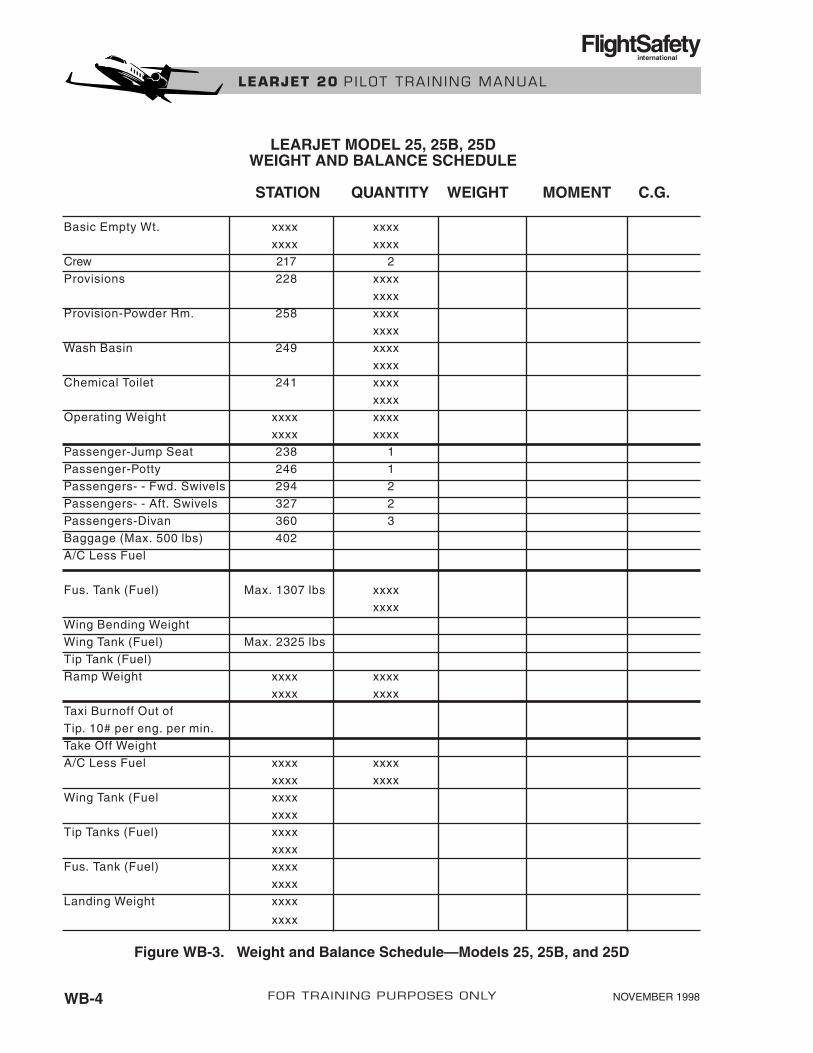
LEARJET MODEL 25, 25B, 25DWEIGHT AND BALANCE SCHEDULE
STATION QUANTITY WEIGHT MOMENT C.G.
Basic Empty Wt. xxxx xxxxxxxx xxxx
Crew 217 2Provisions 228 xxxx
xxxxProvision-Powder Rm. 258 xxxx
xxxxWash Basin 249 xxxx
xxxxChemical Toilet 241 xxxx
xxxxOperating Weight xxxx xxxx
xxxx xxxxPassenger-Jump Seat 238 1Passenger-Potty 246 1Passengers- - Fwd. Swivels 294 2Passengers- - Aft. Swivels 327 2Passengers-Divan 360 3Baggage (Max. 500 lbs) 402A/C Less Fuel
Fus. Tank (Fuel) Max. 1307 lbs xxxxxxxx
Wing Bending WeightWing Tank (Fuel) Max. 2325 lbsTip Tank (Fuel)Ramp Weight xxxx xxxx
xxxx xxxxTaxi Burnoff Out ofTip. 10# per eng. per min.Take Off WeightA/C Less Fuel xxxx xxxx
xxxx xxxxWing Tank (Fuel xxxx
xxxxTip Tanks (Fuel) xxxx
xxxxFus. Tank (Fuel) xxxx
xxxxLanding Weight xxxx
xxxx
NOVEMBER 1998WB-4 FOR TRAINING PURPOSES ONLY
LEARJET 20 P ILOT TRA IN ING MANUAL
FlightSafetyinternational
Figure WB-3. Weight and Balance Schedule—Models 25, 25B, and 25D

LEARJET MODEL 25C/FWEIGHT AND BALANCE SCHEDULE
STATION QUANTITY WEIGHT MOMENT C.G.
Basic Empty Wt. xxxx xxxxxxxx xxxx
Crew 217 2Provisions 230 xxxx
xxxxOperating Weight xxxx xxxx
xxxx xxxxPassenger-Potty 250 1Passengers - Fixed 284 2Passengers - Fwd. Swivels 294 2Passengers - Aft. Swivels 327 2Passenger-Divan 337 2Baggage (Max. 500 lbs) 360A/C Less FuelFus. Tank (Fuel) Max. 2600 lbs xxxx
xxxxWing Bending WeightWing Tank (Fuel) Max. 2325 lbsTip Tank (Fuel) Max. 2466 lbsRamp Weight xxxx xxxx
xxxx xxxxTaxi Burnoff Out ofTip. 10# per eng. per min.Take Off WeightA/C Less Fuel xxxx xxxx
xxxx xxxxWing Tank (Fuel xxxx
xxxxTip Tanks (Fuel) xxxx
xxxxFus. Tank (Fuel) xxxx
xxxxLanding Weight xxxx
xxxx
NOVEMBER 1998 WB-5FOR TRAINING PURPOSES ONLY
LEARJET 20 P ILOT TRA IN ING MANUAL
FlightSafetyinternational
Figure WB-4. Weight and Balance Schedule—Models 25C/F
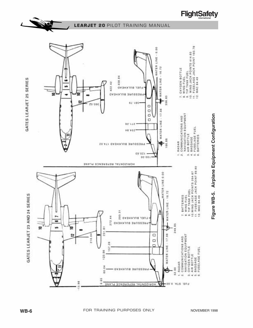
NOVEMBER 1998WB-6 FOR TRAINING PURPOSES ONLY
LEARJET 20 P ILOT TRA IN ING MANUAL
FlightSafetyinternational
Fig
ure
WB
-5.
Air
pla
ne
Eq
uip
men
t C
on
fig
ura
tio
n

NOVEMBER 1998 CRM-i
CREW RESOURCE MANAGEMENT
CONTENTS
Page
CREW RESOURCE MANAGEMENT (CRM)............................................................... CRM-1
FOR TRAINING PURPOSES ONLY
LEARJET 20 P ILOT TRA IN ING MANUAL
FlightSafetyinternational
NOVEMBER 1998 CRM-iii
ILLUSTRATIONS
Figure Title Page
CRM-1 Situational Awareness in the Cockpit ................................................................ CRM-1
CRM-2 Command and Leadership................................................................................. CRM-1
CRM-3 Communication Process .................................................................................... CRM-2
CRM-4 Decision Making Process .................................................................................. CRM-2
FOR TRAINING PURPOSES ONLY
LEARJET 20 P ILOT TRA IN ING MANUAL
FlightSafetyinternational

CREW RESOURCE MANAGEMENT(CRM)
NOVEMBER 1998 CRM-1FOR TRAINING PURPOSES ONLY
LEARJET 20 P ILOT TRA IN ING MANUAL
FlightSafetyinternational
CAPTAININDIVIDUAL
S/A
COPILOTINDIVIDUAL
S/A
GROUPS/A
REMEMBER
2 + 2 = 2
– or –
2 + 2 = 5(Synergy)
IT'S UP TO YOU!
CLUES TO IDENTIFYING:• Loss of Situational Awareness• Links in the Error Chain
HU
MA
NO
PE
RA
TIO
NA
L 1. FAILURE TO MEET TARGETS2. UNDOCUMENTED PROCEDURE3. DEPARTURE FROM SOP4. VIOLATING MINIMUMS OR LIMITATIONS5. NO ONE FLYING AIRPLANE6. NO ONE LOOKING OUT WINDOW
7. COMMUNICATIONS 8. AMBIGUITY 9. UNRESOLVED DISCREPANCIES10. PREOCCUPATION OR DISTRACTION11. CONFUSION OR EMPTY FEELING12.
Figure CRM-1. Situational Awareness in the Cockpit
LEADERSHIP STYLES
PARTICIPATION
LOW HIGH
Command — Designated by Organization — Cannot be Shared
Leadership — Shared among Crewmembers— Focuses on "What's right," not "Who's right"
AUTOCRATIC
STYLE
(EXTREME)
AUTHORITARIAN
LEADERSHIP
STYLE
DEMOCRATIC
LEADERSHIP
STYLE
LAISSEZ-
FAIRE
STYLE
(EXTREME)
Figure CRM-2. Command and Leadership
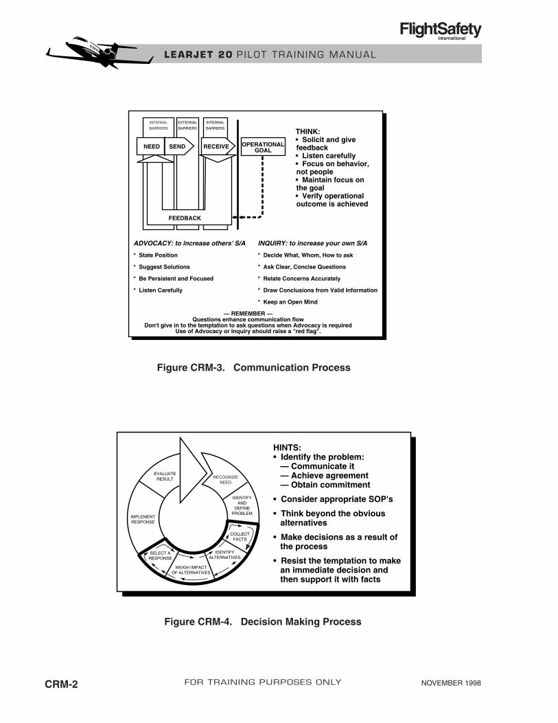
NOVEMBER 1998CRM-2 FOR TRAINING PURPOSES ONLY
LEARJET 20 P ILOT TRA IN ING MANUAL
FlightSafetyinternational
INTERNAL
BARRIERS
EXTERNAL
BARRIERS
INTERNAL
BARRIERS
NEED SEND RECEIVE
FEEDBACK
OPERATIONALGOAL
THINK:• Solicit and givefeedback• Listen carefully• Focus on behavior,not people• Maintain focus onthe goal• Verify operationaloutcome is achieved
ADVOCACY: to increase others' S/A
* State Position
* Suggest Solutions * Be Persistent and Focused
* Listen Carefully
INQUIRY: to increase your own S/A
* Decide What, Whom, How to ask
* Ask Clear, Concise Questions * Relate Concerns Accurately
* Draw Conclusions from Valid Information
* Keep an Open Mind
— REMEMBER —Questions enhance communication flow
Don't give in to the temptation to ask questions when Advocacy is requiredUse of Advocacy or Inquiry should raise a "red flag".
RECOGNIZENEED
IDENTIFYAND
DEFINEPROBLEM
COLLECTFACTS
IDENTIFYALTERNATIVES
WEIGH IMPACTOF ALTERNATIVES
SELECT ARESPONSE
IMPLEMENTRESPONSE
EVALUATERESULT
HINTS:• Identify the problem: — Communicate it — Achieve agreement — Obtain commitment
• Consider appropriate SOP's
• Think beyond the obvious alternatives
• Make decisions as a result of the process
• Resist the temptation to make an immediate decision and then support it with facts
Figure CRM-4. Decision Making Process
Figure CRM-3. Communication Process