floating structure and wind turbine transportation...
TRANSCRIPT
FLOATGEN is co-financed by the European Commission’s
7th Framework Programme for Research and Technological Innovation.
FLOATING STRUCTURE AND WIND TURBINE TRANSPORTATION PROCEDURE Deliverable nº 5.1 EC-GA nº: 295977 Project full title: Demonstration and benchmarking of a floating wind turbine system for power generation in Atlantic deep waters
2
FLOATGEN is co-financed by the European Commission’s 7th Framework Programme for Research and Technological Innovation.
Deliverable Nº 5.1
FLOATING STRUCTURE AND WIND TURBINE TRANSPORTATION PROCEDURE
Responsible Partner: IDEOL & GAMESA
Due Date of Deliverable: 30/04/2015
WP: 5
WP leader: IDEOL
Task: Task 5.1 to 5.4
Task leader: IDEOL
Version: 1
Version date: 30/04/2015
Written by: IDEOL / BYTP / GAMESA
Checked by: IDEOL
Approved by: IDEOL
Dissemination level:
Document history:
Version Date Main Modification Written by Checked by Approved by
1 30/04/2015 - IDEOL
BYTP
GAMESA
IDEOL IDEOL
Brief Summary
This document outlines the transportation and logistics works that will be implemented in
the frame of the Floatgen project. This procedure describes the methods and means
envisaged for the transportation of the floater and Wind Turbine components. Finally the
launching of the floater and the transportation of the FWT to the offshore site will be
described in detail.
3
FLOATGEN is co-financed by the European Commission’s 7th Framework Programme for Research and Technological Innovation.
TABLE OF CONTENTS
1. EXECUTIVE SUMMARY ................................................................................................................................. 5
2. INTRODUCTION ............................................................................................................................................ 5
2.1 DOCUMENT REFERENCES ..................................................................................................................................... 5
2.2 ACRONYMS ...................................................................................................................................................... 6
3. MOORING SYSTEM TRANSPORTATION ......................................................................................................... 7
3.1 MOORING COMPONENTS .................................................................................................................................... 7
3.1.1 Anchors .................................................................................................................................................. 7
3.1.2 Chains .................................................................................................................................................... 7
3.1.3 Forged Fittings ....................................................................................................................................... 8
3.1.4 Nylon Ropes ........................................................................................................................................... 8
3.1.5 Permanent Buoys ................................................................................................................................... 9
3.1.6 Clump Weights....................................................................................................................................... 9
3.2 LOGISTICS IN SAINT-NAZAIRE AND STORAGE ......................................................................................................... 10
3.2.1 Project Storage Area ............................................................................................................................ 10
3.2.2 Local means ......................................................................................................................................... 11
3.2.3 Agent ................................................................................................................................................... 12
3.3 LOAD-OUT ONTO INSTALLATION VESSEL ............................................................................................................... 12
3.3.1 Loading of equipment .......................................................................................................................... 12
3.3.2 Spooling of nylon ropes ....................................................................................................................... 13
3.3.3 Load-out of chains ............................................................................................................................... 14
3.3.4 Anchor assembly .................................................................................................................................. 14
3.3.5 Lashing ................................................................................................................................................. 15
4. FLOATER TRANSPORTATION....................................................................................................................... 16
4.2 FLOATING STRUCTURE COMPONENTS TRANSPORTATION .......................................................................................... 18
4.2.1 Construction formworks ...................................................................................................................... 18
4.2.2 Reinforcement steel ............................................................................................................................. 19
4.2.3 Ready mix concrete .............................................................................................................................. 19
4.2.4 Heavy steel parts ................................................................................................................................. 20
4.3 FLOATER SKIDDING, LOAD OUT AND LAUNCHING .................................................................................................... 21
4.3.1 General description .............................................................................................................................. 21
4.3.2 Engineering .......................................................................................................................................... 22
4.3.3 Mobilization of equipment .................................................................................................................. 25
4
FLOATGEN is co-financed by the European Commission’s 7th Framework Programme for Research and Technological Innovation.
4.3.4 Floater skidding and load out .............................................................................................................. 26
4.3.5 Launching the floater ........................................................................................................................... 29
4.3.6 Towing back to the integration berth .................................................................................................. 30
5. WIND TURBINE TRANSPORTATION ............................................................................................................ 31
5.1 GENERAL ....................................................................................................................................................... 31
5.2 WIND TURBINE TOWER .................................................................................................................................... 31
5.3 ROTOR NACELLE ASSEMBLY ............................................................................................................................... 33
5.4 HUB .............................................................................................................................................................. 35
5.5 BLADES .......................................................................................................................................................... 36
5.6 ACCESSORIES AND ADDITIONAL COMPONENTS ...................................................................................................... 37
5.7 OFFLOADING IN SAINT-NAZAIRE AND STORAGE ..................................................................................................... 38
5.8 WIND TURBINE INTEGRATION ............................................................................................................................ 39
6. FWT TOWING ............................................................................................................................................. 41
6.1 AUTHORIZATION .............................................................................................................................................. 41
6.2 PORT AVAILABLE FLEET...................................................................................................................................... 41
6.3 HARBOUR TOW ............................................................................................................................................... 42
6.4 SEA GOING TOW .............................................................................................................................................. 44
6.5 SPECIAL EQUIPMENT FOR THE TOW ..................................................................................................................... 46
6.5.1 Navigation lights and shapes............................................................................................................... 47
6.5.2 Various equipment............................................................................................................................... 47
6.5.3 Authorisation for sailing ...................................................................................................................... 48
5
FLOATGEN is co-financed by the European Commission’s 7th Framework Programme for Research and Technological Innovation.
1. EXECUTIVE SUMMARY
The deliverable 5.1 “FLOATING STRUCTURE AND WIND TURBINE TRANSPORTATION
PROCEDURE” is presenting the construction and assembly works jointly done by GAMESA,
BYTP and IDEOL. The document outlines the transportation plan for all the components of
the FWT: the hull parts, the wind turbine and the mooring components. In addition we
describe the launching of the hull, the assembly of the wind turbine onto the deck and finally
we provide details on the towing procedure of the FWT to the offshore site.
2. INTRODUCTION
Construction site, WT integration and offshore site engineering has lead to the selection of a
the “quay of Charbonniers” in Saint-Nazaire for the floater construction. It is the Contractors
responsibility to bring all the components of the hull as well as the wind turbine components
and the mooring system, to the port of Saint-Nazaire. All the constituents will be brought by
road, or by cargo ship. In order to handle the parcels of any size, the port is equipped with all
the facilities, and some temporary storage places where needed.
2.1 DOCUMENT REFERENCES
Standards and regulations
[R01] International Regulations for Preventing Collisions at Sea, 1972 amended 1996
[R02] Noble Denton – Guidelines for marine transportations – April 2002
[R03] IMO guidelines for ocean towing, resolution A765 (18)
[R04] DNV-OS-H201 Load Transfer Operations
[R05] IMO Code of Safe Practice for Cargo Securing and Stowing
Project documents
[S01] G02-CN-HYD-5508_Towing_Analysis
[S02] G02-MS-INS-9824_Towing Method Statement
[S03] G02-MS-CON-9607 Launching and harbour towing Method Statement
[S04] G02-MS-MAR-9704 Wind Turbine Integration Method Statement
[S05] G02.DW.INS.9387.00.A1 Mooring equipment arrangement on quay (draft)
6
FLOATGEN is co-financed by the European Commission’s 7th Framework Programme for Research and Technological Innovation.
[S06] G02-MS-INS-9823-00_C2 - Pre-Installation Method Statement
[S07] GP202631 - FASS TRANSPORT PROCESS LG9X – GAMESA PROCEDURE
[S08] GP122282 - FASS WTG SG9X – Assembly and tooling procedure GAMESA
[S09] BYTP Construction method statement – Floatgen project
Other publications
[T01] Le Grand Port Maritime de Nantes - Saint-Nazaire – Haut Comité Français pour
la Défense Civile et Economique des Pays de la Loire – March 2011
2.2 ACRONYMS
AIS Automatic Identification System
CROSS Centre Régional Opérationnel de Surveillance et Sauvetage
DGNSS Differential Global Navigation Satellite System
FWT Floating Wind Turbine. The whole floating system producing power to the grid.
It includes the wind turbine, the floating foundation and the umbilical system.
HS Significant wave height
Kt knot
MWS Marine Warranty Surveyor
nm Nautical mile
SOG Speed Over Ground
TP Transition Piece
TP Wave spectrum peak period
WTG Wind Turbine Generator
7
FLOATGEN is co-financed by the European Commission’s 7th Framework Programme for Research and Technological Innovation.
3. MOORING SYSTEM TRANSPORTATION
3.1 MOORING COMPONENTS
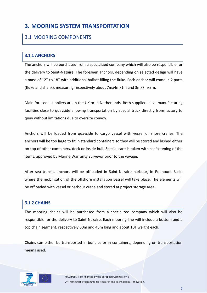
3.1.1 ANCHORS
The anchors will be purchased from a specialized company which will also be responsible for
the delivery to Saint-Nazaire. The foreseen anchors, depending on selected design will have
a mass of 12T to 18T with additional ballast filling the fluke. Each anchor will come in 2 parts
(fluke and shank), measuring respectively about 7mx4mx1m and 3mx7mx3m.
Main foreseen suppliers are in the UK or in Netherlands. Both suppliers have manufacturing
facilities close to quayside allowing transportation by special truck directly from factory to
quay without limitations due to oversize convoy.
Anchors will be loaded from quayside to cargo vessel with vessel or shore cranes. The
anchors will be too large to fit in standard containers so they will be stored and lashed either
on top of other containers, deck or inside hull. Special care is taken with seafastening of the
items, approved by Marine Warranty Surveyor prior to the voyage.
After sea transit, anchors will be offloaded in Saint-Nazaire harbour, in Penhouet Basin
where the mobilisation of the offshore installation vessel will take place. The elements will
be offloaded with vessel or harbour crane and stored at project storage area.
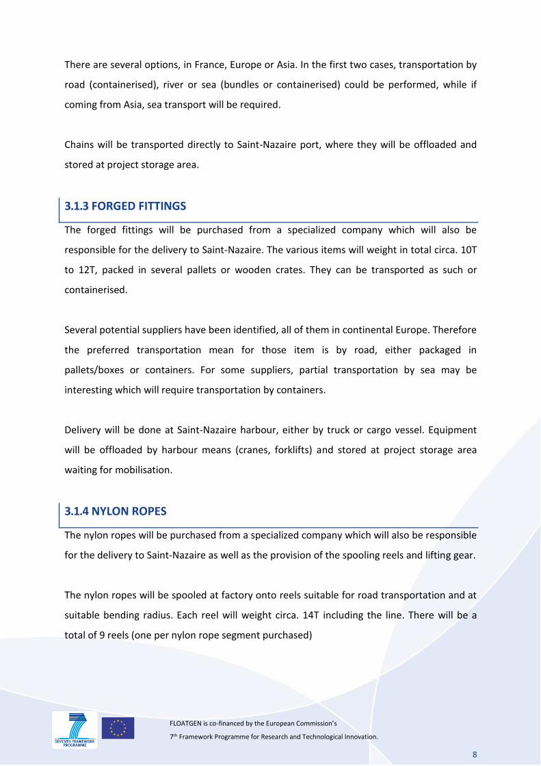
3.1.2 CHAINS
The mooring chains will be purchased from a specialized company which will also be
responsible for the delivery to Saint-Nazaire. Each mooring line will include a bottom and a
top chain segment, respectively 60m and 45m long and about 10T weight each.
Chains can either be transported in bundles or in containers, depending on transportation
means used.
8
FLOATGEN is co-financed by the European Commission’s 7th Framework Programme for Research and Technological Innovation.
There are several options, in France, Europe or Asia. In the first two cases, transportation by
road (containerised), river or sea (bundles or containerised) could be performed, while if
coming from Asia, sea transport will be required.
Chains will be transported directly to Saint-Nazaire port, where they will be offloaded and
stored at project storage area.
3.1.3 FORGED FITTINGS
The forged fittings will be purchased from a specialized company which will also be
responsible for the delivery to Saint-Nazaire. The various items will weight in total circa. 10T
to 12T, packed in several pallets or wooden crates. They can be transported as such or
containerised.
Several potential suppliers have been identified, all of them in continental Europe. Therefore
the preferred transportation mean for those item is by road, either packaged in
pallets/boxes or containers. For some suppliers, partial transportation by sea may be
interesting which will require transportation by containers.
Delivery will be done at Saint-Nazaire harbour, either by truck or cargo vessel. Equipment
will be offloaded by harbour means (cranes, forklifts) and stored at project storage area
waiting for mobilisation.
3.1.4 NYLON ROPES
The nylon ropes will be purchased from a specialized company which will also be responsible
for the delivery to Saint-Nazaire as well as the provision of the spooling reels and lifting gear.
The nylon ropes will be spooled at factory onto reels suitable for road transportation and at
suitable bending radius. Each reel will weight circa. 14T including the line. There will be a
total of 9 reels (one per nylon rope segment purchased)
9
FLOATGEN is co-financed by the European Commission’s 7th Framework Programme for Research and Technological Innovation.
Supplier has been selected, and manufacturing plant is located in Belgium. Supplier is
planning to ship reels by truck to Saint-Nazaire (oversize convoy, requiring an escort car and
specific route) as it is the most competitive solution.
Once arrived in Saint-Nazaire, reels will be offloaded by harbour cranes and stored at project
storage area.
3.1.5 PERMANENT BUOYS
The permanent buoys for nylon ropes will be purchased from a specialized company which
will also be responsible for the delivery to Saint-Nazaire. The various items will weight in
total from 12T to 24T (depending on whether minimal quantity is ordered or quantity for
marine growth compensation), packed in several wooden crates. They can be transported as
such or containerised.
Several potential suppliers have been identified, all of them in Europe. Therefore the
preferred transportation mean for those items is by road, either packaged in crates or
containers.
Delivery will be done at Saint-Nazaire harbour by truck. Equipment will be offloaded by
harbour means (cranes, forklifts) and stored at project storage area waiting for mobilisation.
3.1.6 CLUMP WEIGHTS
The 6 clump weights to be installed on top mooring chains will be purchased from a
specialized company which will also be responsible for the delivery to Saint-Nazaire. Each
item will weight 20T. The weight should not allow packaging in pallets or containers so the
clump weights will probably be transported loose, on trucks. They will be equipped with a
suitable handling rigging
Screening for potential suppliers has not been performed yet, but it is foreseen that a local
steelworks manufacturer will be selected given the naval industry subcontractors network in
10
FLOATGEN is co-financed by the European Commission’s 7th Framework Programme for Research and Technological Innovation.
Saint-Nazaire area. Therefore the preferred transportation mean for those items is by road,
on truck.
Delivery will be done at Saint-Nazaire harbour. Equipment will be offloaded by harbour
means (cranes) and stored at project storage area waiting for mobilisation.
3.2 LOGISTICS IN SAINT-NAZAIRE AND STORAGE
3.2.1 PROJECT STORAGE AREA
All the equipment that will be required at time of offshore installation (including mooring
system components) will be stored on a dedicated project storage area after their delivery
waiting for the mobilisation on the installation vessels.
This area will be rented to Saint-Nazaire harbour and will ideally be located close to a quay
where the mobilisation of the installation vessels can take place, in Penhouet Basin, near
Quay des Charbonniers.
This area is well connected to road network and is used as the main port terminal for heavy
lifts and bulky items loading onto cargo vessels, and is commonly used for temporary storage
of shipped items.
11
FLOATGEN is co-financed by the European Commission’s 7th Framework Programme for Research and Technological Innovation.
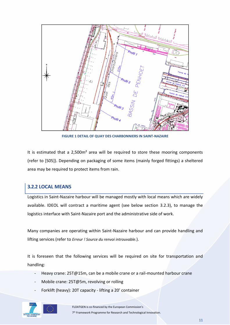
FIGURE 1 DETAIL OF QUAY DES CHARBONNIERS IN SAINT-NAZAIRE
It is estimated that a 2,500m² area will be required to store these mooring components
(refer to [S05]). Depending on packaging of some items (mainly forged fittings) a sheltered
area may be required to protect items from rain.
3.2.2 LOCAL MEANS
Logistics in Saint-Nazaire harbour will be managed mostly with local means which are widely
available. IDEOL will contract a maritime agent (see below section 3.2.3), to manage the
logistics interface with Saint-Nazaire port and the administrative side of work.
Many companies are operating within Saint-Nazaire harbour and can provide handling and
lifting services (refer to Erreur ! Source du renvoi introuvable.).
It is foreseen that the following services will be required on site for transportation and
handling:
- Heavy crane: 25T@15m, can be a mobile crane or a rail-mounted harbour crane
- Mobile crane: 25T@5m, revolving or rolling
- Forklift (heavy): 20T capacity - lifting a 20’ container
12
FLOATGEN is co-financed by the European Commission’s 7th Framework Programme for Research and Technological Innovation.
- Forklift (light): 2T to 5T capacity, for pallets handling
- Set of rigging for lifting of items
3.2.3 AGENT
Management and sourcing of local workforce, lifting and handling means will be performed
through a maritime agent who is also qualified for stevedoring operations.
The maritime agent will also be in charge of managing the logistics procedures and
paperwork, including interface with customs if required for elements imported from outside
UE.
The agent will also manage the various aspects of the installation vessel support such as port
master interface, rental of quay and fenders, providing useful contacts for ship-chandling,
etc.
Preliminary discussions on various subjects related to Floatgen project has been conducted
with SOGEBRAS, one of the most active shipping agent operating in Saint-Nazaire. SOGEBRAS
is therefore foreseen to provide the maritime agent services for the logistics but also
installation phases of Floatgen project in Saint-Nazaire.
3.3 LOAD-OUT ONTO INSTALLATION VESSEL
3.3.1 LOADING OF EQUIPMENT
Mobilisation of the offshore installation vessel will take place in Saint-Nazaire harbour, in
Penhouet Basin. The inbound mooring components will be transported from project storage
area to the final mobilisation quay, where they can be loaded on installation vessel. Harbour
cranes and means will be used for handling.
The installation vessel for mooring lines pre-lay will be a large Anchor Handling Vessel (AHV),
circa. 80m to 90m long. The rest of the equipment can be loaded with the vessel moored
alongside quay.
13
FLOATGEN is co-financed by the European Commission’s 7th Framework Programme for Research and Technological Innovation.
Mooring components will be lifted from quayside onto vessel deck where they will be
repositioned if required with vessel cranes. Finally all equipment stored on deck will be
seafastened to ensure a safe sea transportation and installation operation.
The load-out of mooring system components is described in the mooring pre-installation
method statement (refer to [S06]).
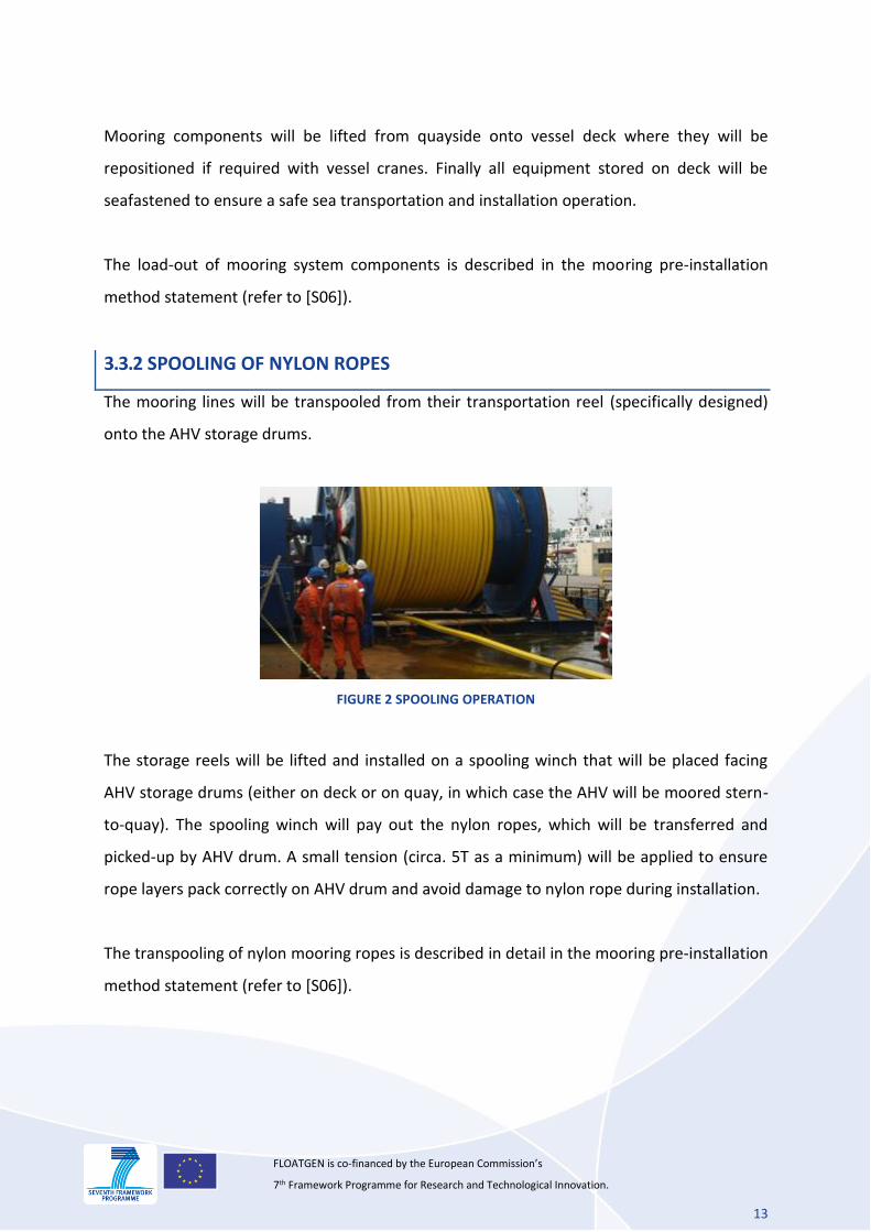
3.3.2 SPOOLING OF NYLON ROPES
The mooring lines will be transpooled from their transportation reel (specifically designed)
onto the AHV storage drums.
FIGURE 2 SPOOLING OPERATION
The storage reels will be lifted and installed on a spooling winch that will be placed facing
AHV storage drums (either on deck or on quay, in which case the AHV will be moored stern-
to-quay). The spooling winch will pay out the nylon ropes, which will be transferred and
picked-up by AHV drum. A small tension (circa. 5T as a minimum) will be applied to ensure
rope layers pack correctly on AHV drum and avoid damage to nylon rope during installation.
The transpooling of nylon mooring ropes is described in detail in the mooring pre-installation
method statement (refer to [S06]).
14
FLOATGEN is co-financed by the European Commission’s 7th Framework Programme for Research and Technological Innovation.
3.3.3 LOAD-OUT OF CHAINS
The chain will be taken out of storage area and brought alongside quay in bundles with its
lifting slings in place. Bundles will be lifted onto installation vessel deck.
Installation vessel is equipped with suitable gipsy wheels for loading chains into its chain
lockers. Chains will be connected to each other with dedicated rigging to form a long section
and ease handling and retrieval of chain segments from lockers.
In the unlikely situation where the installation vessel is not able to transfer the chains in its
lockers (or if suitable room is not available) then the chains will be laid flat on deck,
untwisted, and lashed for sea transportation.
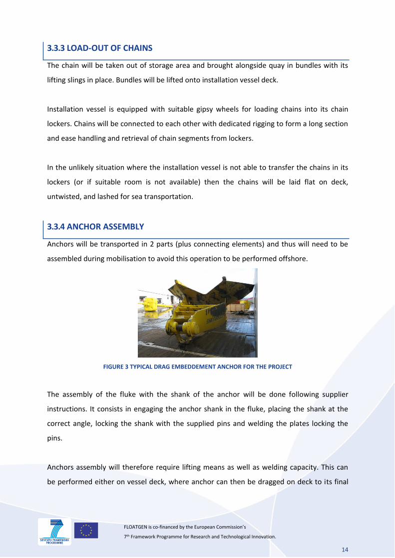
3.3.4 ANCHOR ASSEMBLY
Anchors will be transported in 2 parts (plus connecting elements) and thus will need to be
assembled during mobilisation to avoid this operation to be performed offshore.
FIGURE 3 TYPICAL DRAG EMBEDDEMENT ANCHOR FOR THE PROJECT
The assembly of the fluke with the shank of the anchor will be done following supplier
instructions. It consists in engaging the anchor shank in the fluke, placing the shank at the
correct angle, locking the shank with the supplied pins and welding the plates locking the
pins.
Anchors assembly will therefore require lifting means as well as welding capacity. This can
be performed either on vessel deck, where anchor can then be dragged on deck to its final
15
FLOATGEN is co-financed by the European Commission’s 7th Framework Programme for Research and Technological Innovation.
position for lashing, or on quayside, where the assembled anchor is then lifted on vessel
deck.
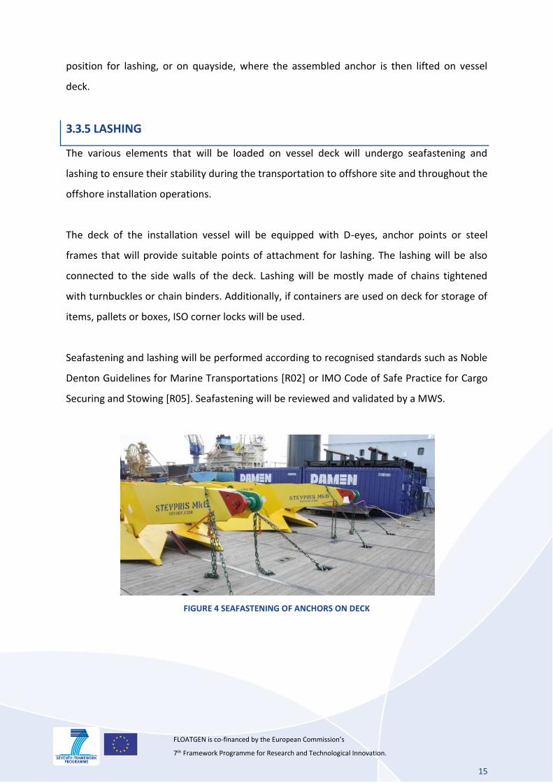
3.3.5 LASHING
The various elements that will be loaded on vessel deck will undergo seafastening and
lashing to ensure their stability during the transportation to offshore site and throughout the
offshore installation operations.
The deck of the installation vessel will be equipped with D-eyes, anchor points or steel
frames that will provide suitable points of attachment for lashing. The lashing will be also
connected to the side walls of the deck. Lashing will be mostly made of chains tightened
with turnbuckles or chain binders. Additionally, if containers are used on deck for storage of
items, pallets or boxes, ISO corner locks will be used.
Seafastening and lashing will be performed according to recognised standards such as Noble
Denton Guidelines for Marine Transportations [R02] or IMO Code of Safe Practice for Cargo
Securing and Stowing [R05]. Seafastening will be reviewed and validated by a MWS.
FIGURE 4 SEAFASTENING OF ANCHORS ON DECK
16
FLOATGEN is co-financed by the European Commission’s 7th Framework Programme for Research and Technological Innovation.
4. FLOATER TRANSPORTATION
This chapter aims at presenting the transportation scheme of the floater. It covers the
components transportation from the manufacturing site up to the yard and the
transportation of the floater itself from the construction site to the WT integration site.
4.1 FLOATER CONSTRUCTION SITE
The floater will be built on a yard of Saint-Nazaire port, owned by the Grand Port Maritime
de Nantes Saint-Nazaire (public organization). Load bearing capacity of the quay is compliant
with the foreseen construction and launching activities. An occupation contract with the
Port is being signed for the duration of the works.
Several ways of communication lead to Saint-Nazaire. A motorway is feeding the hinterland.
The road to the south is naturally passing through the Cheviré bridge which truck capacity is
44 ton.
All of the rail traffic of the port cross Le Croisic, Saint-Nazaire, with possible segregation from
Savenay, either towards Nantes, Angers, the Paris region, the center and the South of
France, or towards Pontchâteau, Redon, Rennes and the West of Brittany.
Very few river transportation is possible beyond Nantes, situated 60 km upstream Saint-
Nazaire.
Accessible by a well-marked out channel, in the daytime and at night, an access of the port
can be made by, more or less, all the weather conditions.
The intended berth where the floater will be built is part of a steady water basin (Penhouët
basin) that will highly facilitate the launching of the structure with no tide range to manage.
The quays are made of masonry with an embankment behind made of sand and alluvial
muddy over the bedrock.
17
FLOATGEN is co-financed by the European Commission’s 7th Framework Programme for Research and Technological Innovation.
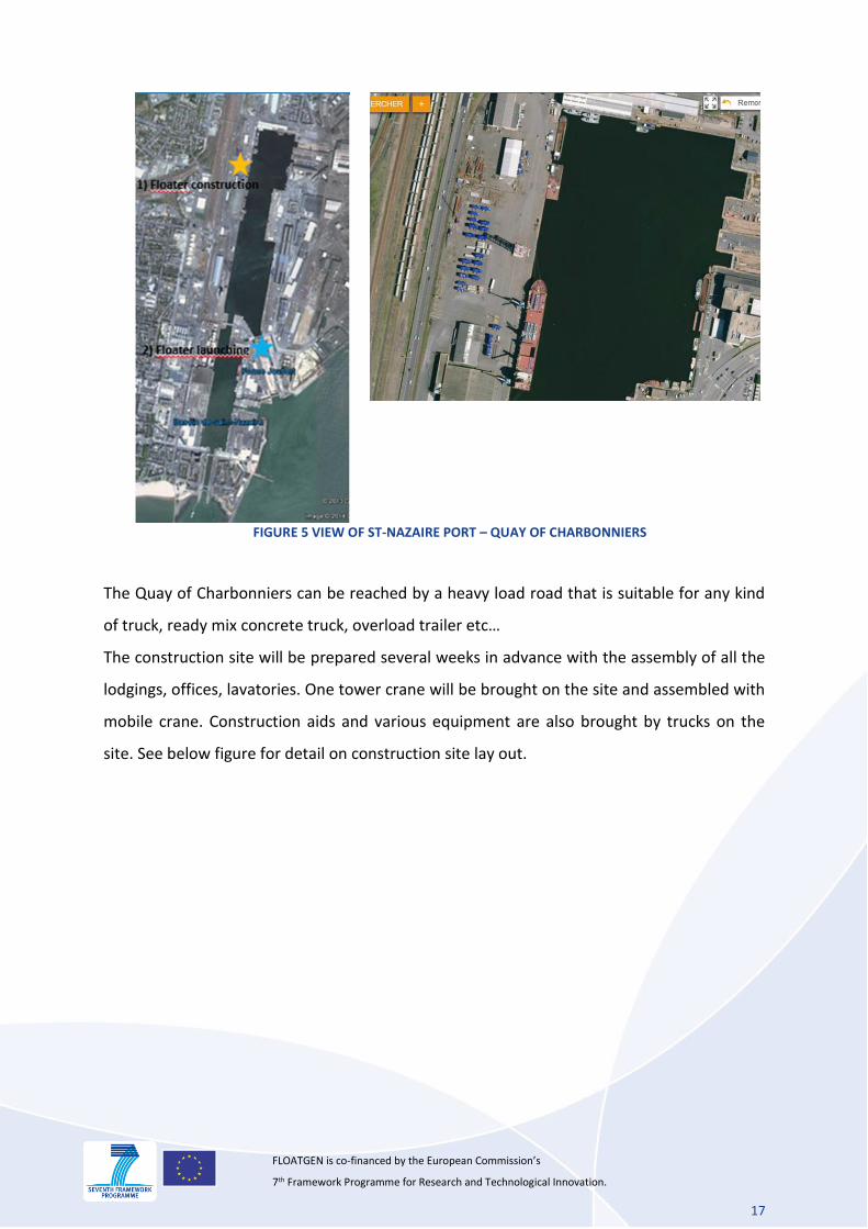
FIGURE 5 VIEW OF ST-NAZAIRE PORT – QUAY OF CHARBONNIERS
The Quay of Charbonniers can be reached by a heavy load road that is suitable for any kind
of truck, ready mix concrete truck, overload trailer etc…
The construction site will be prepared several weeks in advance with the assembly of all the
lodgings, offices, lavatories. One tower crane will be brought on the site and assembled with
mobile crane. Construction aids and various equipment are also brought by trucks on the
site. See below figure for detail on construction site lay out.
18
FLOATGEN is co-financed by the European Commission’s 7th Framework Programme for Research and Technological Innovation.
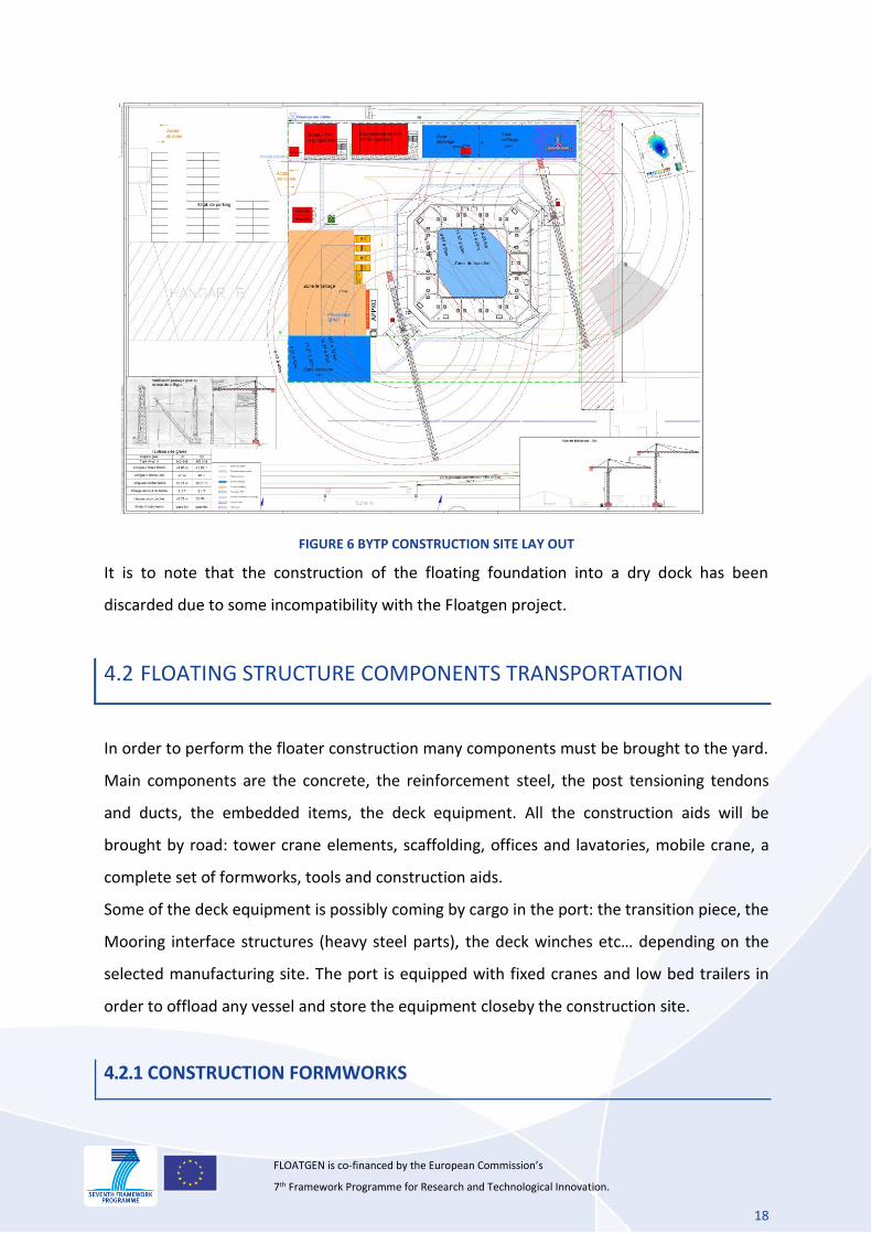
FIGURE 6 BYTP CONSTRUCTION SITE LAY OUT
It is to note that the construction of the floating foundation into a dry dock has been
discarded due to some incompatibility with the Floatgen project.
4.2 FLOATING STRUCTURE COMPONENTS TRANSPORTATION
In order to perform the floater construction many components must be brought to the yard.
Main components are the concrete, the reinforcement steel, the post tensioning tendons
and ducts, the embedded items, the deck equipment. All the construction aids will be
brought by road: tower crane elements, scaffolding, offices and lavatories, mobile crane, a
complete set of formworks, tools and construction aids.
Some of the deck equipment is possibly coming by cargo in the port: the transition piece, the
Mooring interface structures (heavy steel parts), the deck winches etc… depending on the
selected manufacturing site. The port is equipped with fixed cranes and low bed trailers in
order to offload any vessel and store the equipment closeby the construction site.
4.2.1 CONSTRUCTION FORMWORKS
19
FLOATGEN is co-financed by the European Commission’s 7th Framework Programme for Research and Technological Innovation.
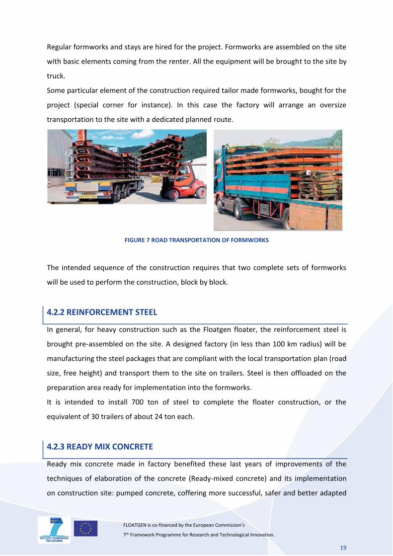
Regular formworks and stays are hired for the project. Formworks are assembled on the site
with basic elements coming from the renter. All the equipment will be brought to the site by
truck.
Some particular element of the construction required tailor made formworks, bought for the
project (special corner for instance). In this case the factory will arrange an oversize
transportation to the site with a dedicated planned route.
FIGURE 7 ROAD TRANSPORTATION OF FORMWORKS
The intended sequence of the construction requires that two complete sets of formworks
will be used to perform the construction, block by block.
4.2.2 REINFORCEMENT STEEL
In general, for heavy construction such as the Floatgen floater, the reinforcement steel is
brought pre-assembled on the site. A designed factory (in less than 100 km radius) will be
manufacturing the steel packages that are compliant with the local transportation plan (road
size, free height) and transport them to the site on trailers. Steel is then offloaded on the
preparation area ready for implementation into the formworks.
It is intended to install 700 ton of steel to complete the floater construction, or the
equivalent of 30 trailers of about 24 ton each.
4.2.3 READY MIX CONCRETE
Ready mix concrete made in factory benefited these last years of improvements of the
techniques of elaboration of the concrete (Ready-mixed concrete) and its implementation
on construction site: pumped concrete, coffering more successful, safer and better adapted
20
FLOATGEN is co-financed by the European Commission’s 7th Framework Programme for Research and Technological Innovation.
to needs - formworks, tables, coffering tunnels, slippery coffering. The quality of the
concrete is improved, there as well as its finish, in particular thanks to the self-compacting
concrete. The industrial production of the ready mix concrete is a quality factor of concrete.
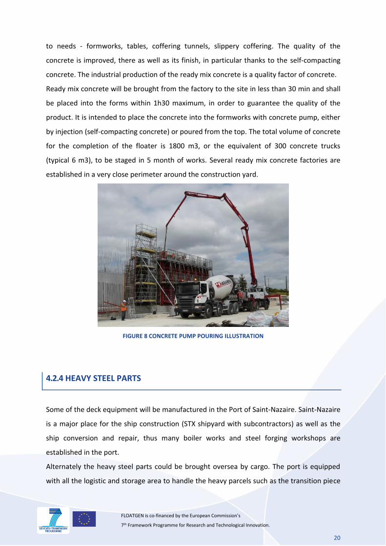
Ready mix concrete will be brought from the factory to the site in less than 30 min and shall
be placed into the forms within 1h30 maximum, in order to guarantee the quality of the
product. It is intended to place the concrete into the formworks with concrete pump, either
by injection (self-compacting concrete) or poured from the top. The total volume of concrete
for the completion of the floater is 1800 m3, or the equivalent of 300 concrete trucks
(typical 6 m3), to be staged in 5 month of works. Several ready mix concrete factories are
established in a very close perimeter around the construction yard.
FIGURE 8 CONCRETE PUMP POURING ILLUSTRATION
4.2.4 HEAVY STEEL PARTS
Some of the deck equipment will be manufactured in the Port of Saint-Nazaire. Saint-Nazaire
is a major place for the ship construction (STX shipyard with subcontractors) as well as the
ship conversion and repair, thus many boiler works and steel forging workshops are
established in the port.
Alternately the heavy steel parts could be brought oversea by cargo. The port is equipped
with all the logistic and storage area to handle the heavy parcels such as the transition piece
21
FLOATGEN is co-financed by the European Commission’s 7th Framework Programme for Research and Technological Innovation.
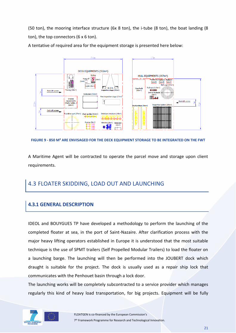
(50 ton), the mooring interface structure (6x 8 ton), the i-tube (8 ton), the boat landing (8
ton), the top connectors (6 x 6 ton).
A tentative of required area for the equipment storage is presented here below:
FIGURE 9 - 850 M² ARE ENVISAGED FOR THE DECK EQUIPMENT STORAGE TO BE INTEGRATED ON THE FWT
A Maritime Agent will be contracted to operate the parcel move and storage upon client
requirements.
4.3 FLOATER SKIDDING, LOAD OUT AND LAUNCHING
4.3.1 GENERAL DESCRIPTION
IDEOL and BOUYGUES TP have developed a methodology to perform the launching of the
completed floater at sea, in the port of Saint-Nazaire. After clarification process with the
major heavy lifting operators established in Europe it is understood that the most suitable
technique is the use of SPMT trailers (Self Propelled Modular Trailers) to load the floater on
a launching barge. The launching will then be performed into the JOUBERT dock which
draught is suitable for the project. The dock is usually used as a repair ship lock that
communicates with the Penhouet basin through a lock door.
The launching works will be completely subcontracted to a service provider which manages
regularly this kind of heavy load transportation, for big projects. Equipment will be fully
22
FLOATGEN is co-financed by the European Commission’s 7th Framework Programme for Research and Technological Innovation.
certified as maritime rules and insurers request. For interface purpose a MWS will review
the procedure and attend the operation.
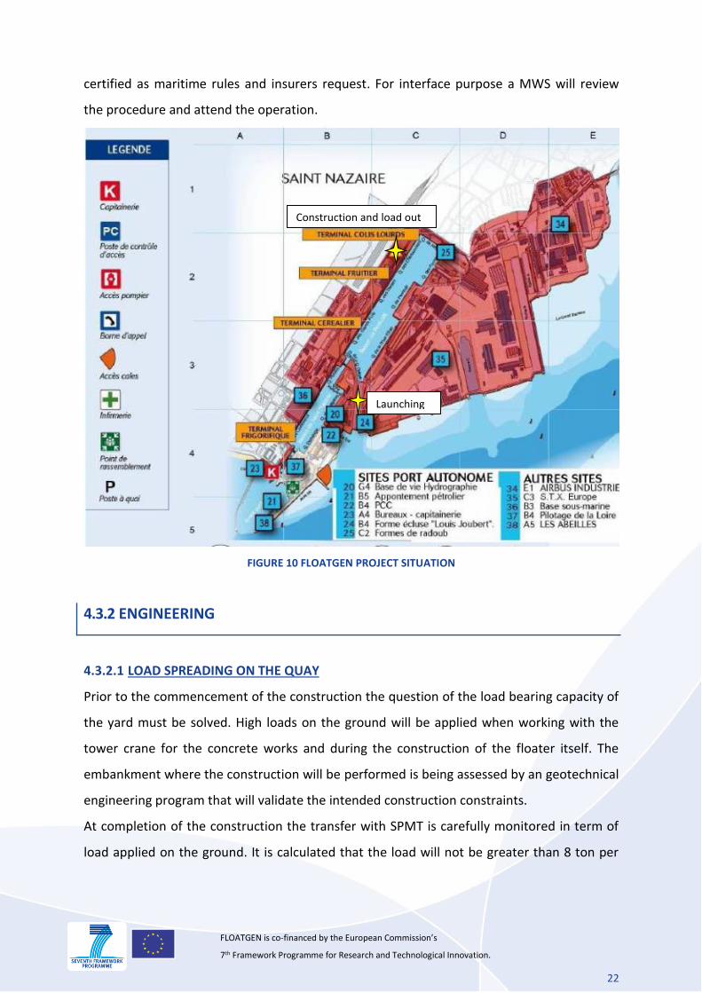
FIGURE 10 FLOATGEN PROJECT SITUATION
4.3.2 ENGINEERING
4.3.2.1 LOAD SPREADING ON THE QUAY
Prior to the commencement of the construction the question of the load bearing capacity of
the yard must be solved. High loads on the ground will be applied when working with the
tower crane for the concrete works and during the construction of the floater itself. The
embankment where the construction will be performed is being assessed by an geotechnical
engineering program that will validate the intended construction constraints.
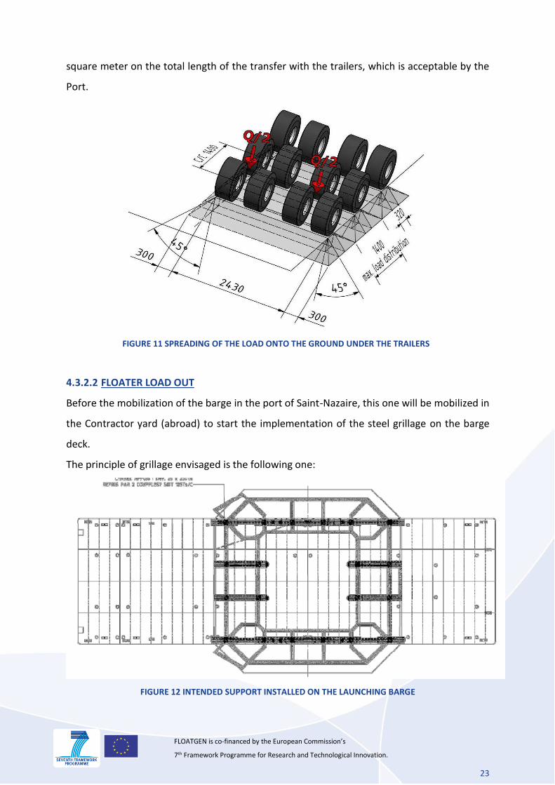
At completion of the construction the transfer with SPMT is carefully monitored in term of
load applied on the ground. It is calculated that the load will not be greater than 8 ton per
Construction and load out
Launching
23
FLOATGEN is co-financed by the European Commission’s 7th Framework Programme for Research and Technological Innovation.
square meter on the total length of the transfer with the trailers, which is acceptable by the
Port.
FIGURE 11 SPREADING OF THE LOAD ONTO THE GROUND UNDER THE TRAILERS
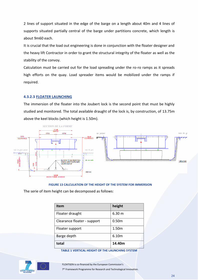
4.3.2.2 FLOATER LOAD OUT
Before the mobilization of the barge in the port of Saint-Nazaire, this one will be mobilized in
the Contractor yard (abroad) to start the implementation of the steel grillage on the barge
deck.
The principle of grillage envisaged is the following one:
FIGURE 12 INTENDED SUPPORT INSTALLED ON THE LAUNCHING BARGE
24
FLOATGEN is co-financed by the European Commission’s 7th Framework Programme for Research and Technological Innovation.
2 lines of support situated in the edge of the barge on a length about 40m and 4 lines of
supports situated partially central of the barge under partitions concrete, which length is
about 9m60 each.
It is crucial that the load out engineering is done in conjunction with the floater designer and
the heavy lift Contractor in order to grant the structural integrity of the floater as well as the
stability of the convoy.
Calculation must be carried out for the load spreading under the ro-ro ramps as it spreads
high efforts on the quay. Load spreader items would be mobilized under the ramps if
required.
4.3.2.3 FLOATER LAUNCHING
The immersion of the floater into the Joubert lock is the second point that must be highly
studied and monitored. The total available draught of the lock is, by construction, of 13.75m
above the keel blocks (which height is 1.50m).
FIGURE 13 CALCULATION OF THE HEIGHT OF THE SYSTEM FOR IMMERSION
The serie of item height can be decomposed as follows:
Item height
Floater draught 6.30 m
Clearance floater - support 0.50m
Floater support 1.50m
Barge depth 6.10m
total 14.40m
TABLE 1 VERTICAL HEIGHT OF THE LAUNCHING SYSTEM
25
FLOATGEN is co-financed by the European Commission’s 7th Framework Programme for Research and Technological Innovation.
From the table above one sees that it is necessary to remove the keel blocks (h=1.50m) to
success the launching. The removal of the dock floor tins will be scheduled during a repair
period of a ship when the dock is empty.
Engineering shows that a suitable barge for the launching is 6.10m deep (20 feet), which is
quite common in the naval industry. Some suitable barges have been identified in the North
Sea.
4.3.3 MOBILIZATION OF EQUIPMENT
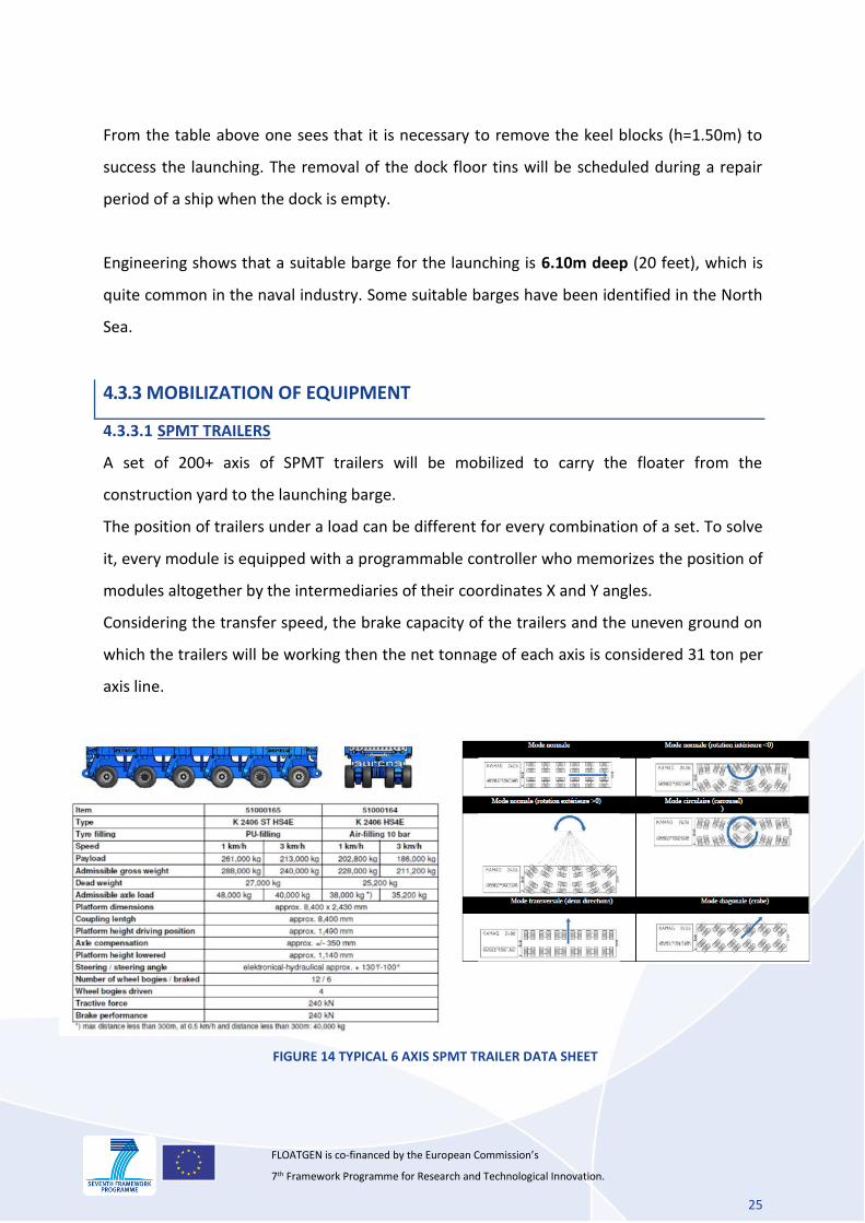
4.3.3.1 SPMT TRAILERS
A set of 200+ axis of SPMT trailers will be mobilized to carry the floater from the
construction yard to the launching barge.
The position of trailers under a load can be different for every combination of a set. To solve
it, every module is equipped with a programmable controller who memorizes the position of
modules altogether by the intermediaries of their coordinates X and Y angles.
Considering the transfer speed, the brake capacity of the trailers and the uneven ground on
which the trailers will be working then the net tonnage of each axis is considered 31 ton per
axis line.
FIGURE 14 TYPICAL 6 AXIS SPMT TRAILER DATA SHEET
26
FLOATGEN is co-financed by the European Commission’s 7th Framework Programme for Research and Technological Innovation.
The stability of a combination of SPMT is granted by an adaptable hydraulic suspension
according to the combination. In the case of a normal operation a suspension on 3 points
will be made by the creation of 3 zones of oil. This significates that the units are hydraulically
connected each other in 3 different groups of trailers. The load is constantly supported by 3
lifting points (resultant force) which guarantees the stability during the transfer.
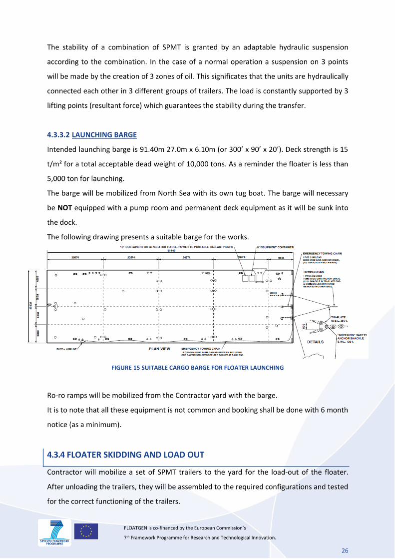
4.3.3.2 LAUNCHING BARGE
Intended launching barge is 91.40m 27.0m x 6.10m (or 300’ x 90’ x 20’). Deck strength is 15
t/m² for a total acceptable dead weight of 10,000 tons. As a reminder the floater is less than
5,000 ton for launching.
The barge will be mobilized from North Sea with its own tug boat. The barge will necessary
be NOT equipped with a pump room and permanent deck equipment as it will be sunk into
the dock.
The following drawing presents a suitable barge for the works.
FIGURE 15 SUITABLE CARGO BARGE FOR FLOATER LAUNCHING
Ro-ro ramps will be mobilized from the Contractor yard with the barge.
It is to note that all these equipment is not common and booking shall be done with 6 month
notice (as a minimum).
4.3.4 FLOATER SKIDDING AND LOAD OUT
Contractor will mobilize a set of SPMT trailers to the yard for the load-out of the floater.
After unloading the trailers, they will be assembled to the required configurations and tested
for the correct functioning of the trailers.
27
FLOATGEN is co-financed by the European Commission’s 7th Framework Programme for Research and Technological Innovation.
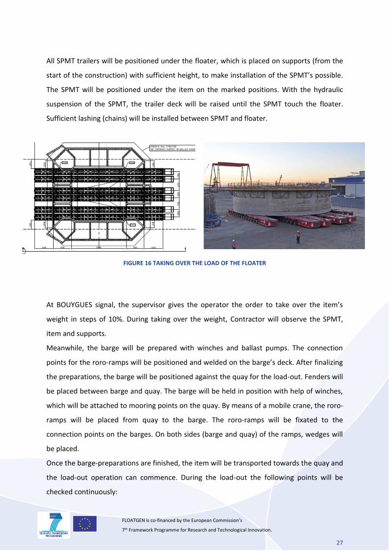
All SPMT trailers will be positioned under the floater, which is placed on supports (from the
start of the construction) with sufficient height, to make installation of the SPMT’s possible.
The SPMT will be positioned under the item on the marked positions. With the hydraulic
suspension of the SPMT, the trailer deck will be raised until the SPMT touch the floater.
Sufficient lashing (chains) will be installed between SPMT and floater.
FIGURE 16 TAKING OVER THE LOAD OF THE FLOATER
At BOUYGUES signal, the supervisor gives the operator the order to take over the item’s
weight in steps of 10%. During taking over the weight, Contractor will observe the SPMT,
item and supports.
Meanwhile, the barge will be prepared with winches and ballast pumps. The connection
points for the roro-ramps will be positioned and welded on the barge’s deck. After finalizing
the preparations, the barge will be positioned against the quay for the load-out. Fenders will
be placed between barge and quay. The barge will be held in position with help of winches,
which will be attached to mooring points on the quay. By means of a mobile crane, the roro-
ramps will be placed from quay to the barge. The roro-ramps will be fixated to the
connection points on the barges. On both sides (barge and quay) of the ramps, wedges will
be placed.
Once the barge-preparations are finished, the item will be transported towards the quay and
the load-out operation can commence. During the load-out the following points will be
checked continuously:
28
FLOATGEN is co-financed by the European Commission’s 7th Framework Programme for Research and Technological Innovation.
Item to be transported.
SPMT trailers.
All lashing connections.
Winches, including wires and mooring points.
Roro-ramps.
Level of the barge
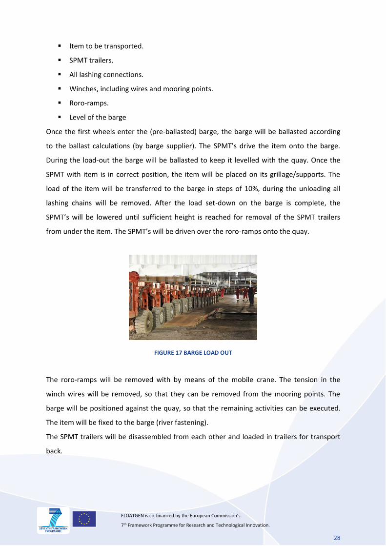
Once the first wheels enter the (pre-ballasted) barge, the barge will be ballasted according
to the ballast calculations (by barge supplier). The SPMT’s drive the item onto the barge.
During the load-out the barge will be ballasted to keep it levelled with the quay. Once the
SPMT with item is in correct position, the item will be placed on its grillage/supports. The
load of the item will be transferred to the barge in steps of 10%, during the unloading all
lashing chains will be removed. After the load set-down on the barge is complete, the
SPMT’s will be lowered until sufficient height is reached for removal of the SPMT trailers
from under the item. The SPMT’s will be driven over the roro-ramps onto the quay.
FIGURE 17 BARGE LOAD OUT
The roro-ramps will be removed with by means of the mobile crane. The tension in the
winch wires will be removed, so that they can be removed from the mooring points. The
barge will be positioned against the quay, so that the remaining activities can be executed.
The item will be fixed to the barge (river fastening).
The SPMT trailers will be disassembled from each other and loaded in trailers for transport
back.
29
FLOATGEN is co-financed by the European Commission’s 7th Framework Programme for Research and Technological Innovation.
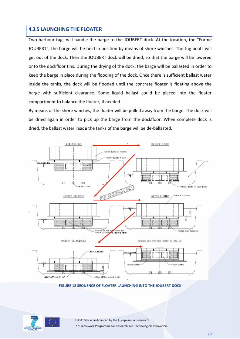
4.3.5 LAUNCHING THE FLOATER
Two harbour tugs will handle the barge to the JOUBERT dock. At the location, the “Forme
JOUBERT”, the barge will be held in position by means of shore winches. The tug boats will
get out of the dock. Then the JOUBERT dock will be dried, so that the barge will be lowered
onto the dockfloor tins. During the drying of the dock, the barge will be ballasted in order to
keep the barge in place during the flooding of the dock. Once there is sufficient ballast water
inside the tanks, the dock will be flooded until the concrete floater is floating above the
barge with sufficient clearance. Some liquid ballast could be placed into the floater
compartment to balance the floater, if needed.
By means of the shore winches, the floater will be pulled away from the barge. The dock will
be dried again in order to pick up the barge from the dockfloor. When complete dock is
dried, the ballast water inside the tanks of the barge will be de-ballasted.
FIGURE 18 SEQUENCE OF FLOATER LAUNCHING INTO THE JOUBERT DOCK
30
FLOATGEN is co-financed by the European Commission’s 7th Framework Programme for Research and Technological Innovation.
When the barge is empty, the offhire survey will take place. The JOUBERT dock will be
flooded after completion of the offhire survey. All equipment can be demobilized.
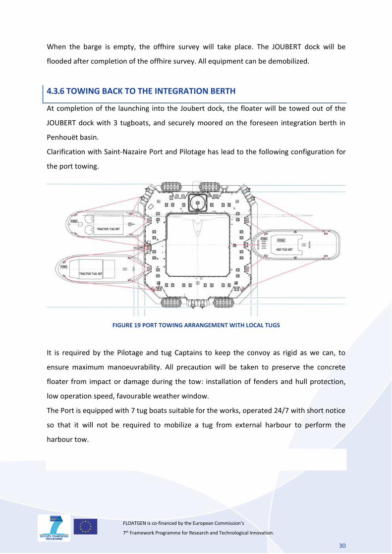
4.3.6 TOWING BACK TO THE INTEGRATION BERTH
At completion of the launching into the Joubert dock, the floater will be towed out of the
JOUBERT dock with 3 tugboats, and securely moored on the foreseen integration berth in
Penhouët basin.
Clarification with Saint-Nazaire Port and Pilotage has lead to the following configuration for
the port towing.
FIGURE 19 PORT TOWING ARRANGEMENT WITH LOCAL TUGS
It is required by the Pilotage and tug Captains to keep the convoy as rigid as we can, to
ensure maximum manoeuvrability. All precaution will be taken to preserve the concrete
floater from impact or damage during the tow: installation of fenders and hull protection,
low operation speed, favourable weather window.
The Port is equipped with 7 tug boats suitable for the works, operated 24/7 with short notice
so that it will not be required to mobilize a tug from external harbour to perform the
harbour tow.
31
FLOATGEN is co-financed by the European Commission’s 7th Framework Programme for Research and Technological Innovation.
5. WIND TURBINE TRANSPORTATION
5.1 GENERAL
The WTG will be procured by GAMESA from an already existing and functioning WTG.
GAMESA will dismantle the elements on an existing onshore wind farm, transport them to
facilities where they will be overhauled and adapted to the needs of Floatgen project and re-
conditioned.
The WTG tower will however be built specifically for this project purpose and will follow a
different transportation route.
All elements will then be shipped from Bilbao to Saint-Nazaire. These operations will be
managed by GAMESA Logistics department, following pre-defined procedures [S07]. At this
stage it is not yet decided whether the WTG tower and other components will be
transported on the same cargo ship.
5.2 WIND TURBINE TOWER
WT Tower will be made in 2 parts. Weight and dimensions of these parts are given in Table
2.
Weight (Ton) Length (m) Breadth (m)
Bottom 77 25 5.2
Top 56 33.5 TBD
Total 133 58.5 n/a
TABLE 2 WT TOWER WEIGHT AND DIMENSIONS
Tower will be manufactured by a supplier selected by GAMESA. Although final decision for
tower manufacturer has not been made yet, the manufacturer most likely to be selected is
WINDAR TADARSA, based in Avilés on Spain North shore.
WINDAR TADARSA facilities are located on an industrial area within 2km of a loading quay
and associated storage area for wind turbine tower components.
32
FLOATGEN is co-financed by the European Commission’s 7th Framework Programme for Research and Technological Innovation.
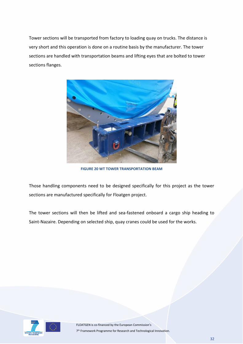
Tower sections will be transported from factory to loading quay on trucks. The distance is
very short and this operation is done on a routine basis by the manufacturer. The tower
sections are handled with transportation beams and lifting eyes that are bolted to tower
sections flanges.
FIGURE 20 WT TOWER TRANSPORTATION BEAM
Those handling components need to be designed specifically for this project as the tower
sections are manufactured specifically for Floatgen project.
The tower sections will then be lifted and sea-fastened onboard a cargo ship heading to
Saint-Nazaire. Depending on selected ship, quay cranes could be used for the works.
33
FLOATGEN is co-financed by the European Commission’s 7th Framework Programme for Research and Technological Innovation.
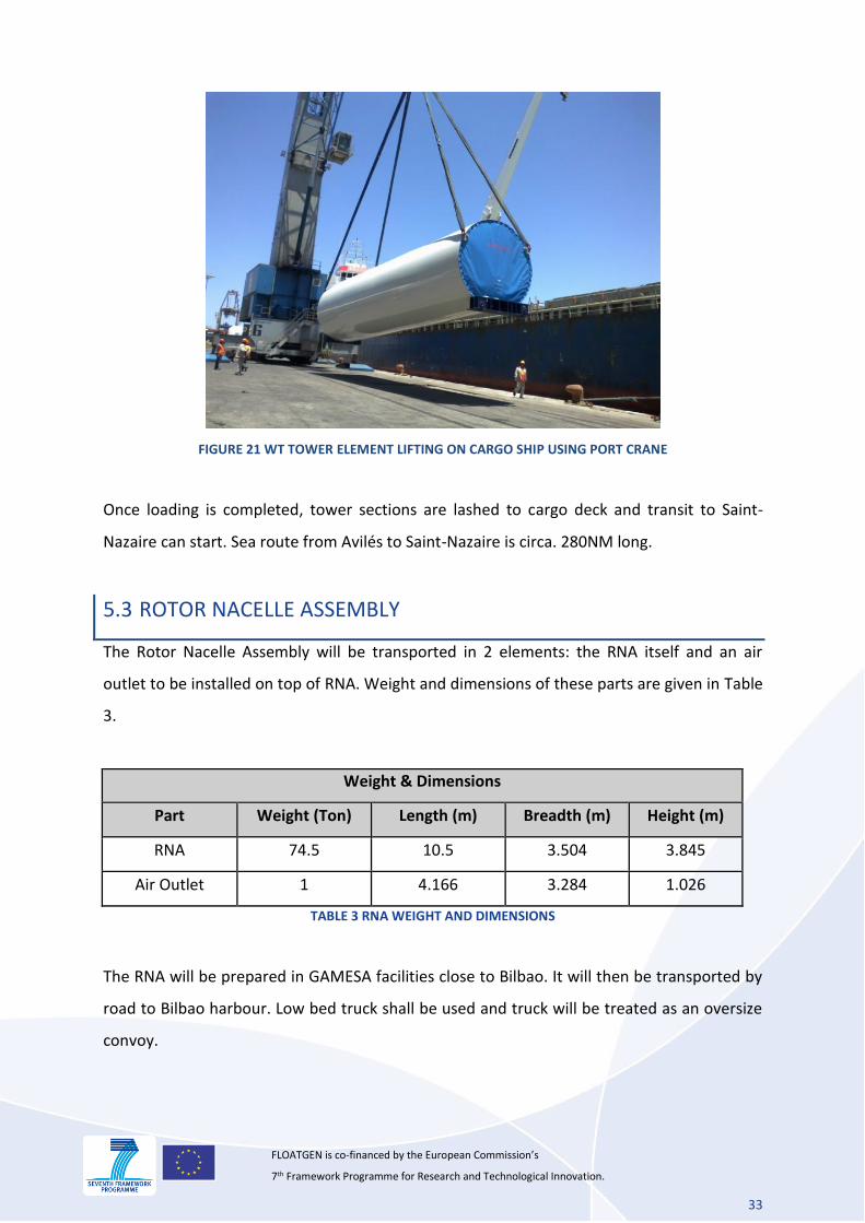
FIGURE 21 WT TOWER ELEMENT LIFTING ON CARGO SHIP USING PORT CRANE
Once loading is completed, tower sections are lashed to cargo deck and transit to Saint-
Nazaire can start. Sea route from Avilés to Saint-Nazaire is circa. 280NM long.
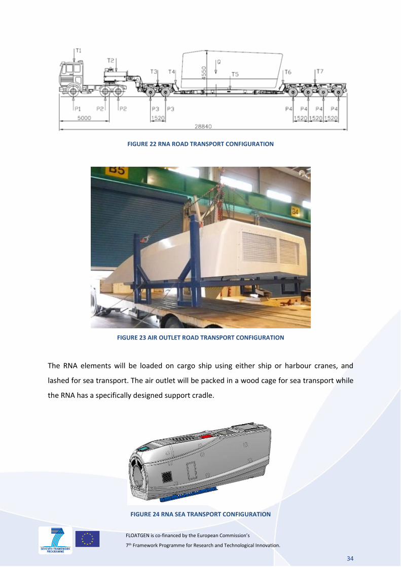
5.3 ROTOR NACELLE ASSEMBLY
The Rotor Nacelle Assembly will be transported in 2 elements: the RNA itself and an air
outlet to be installed on top of RNA. Weight and dimensions of these parts are given in Table
3.
Weight & Dimensions
Part Weight (Ton) Length (m) Breadth (m) Height (m)
RNA 74.5 10.5 3.504 3.845
Air Outlet 1 4.166 3.284 1.026
TABLE 3 RNA WEIGHT AND DIMENSIONS
The RNA will be prepared in GAMESA facilities close to Bilbao. It will then be transported by
road to Bilbao harbour. Low bed truck shall be used and truck will be treated as an oversize
convoy.
34
FLOATGEN is co-financed by the European Commission’s 7th Framework Programme for Research and Technological Innovation.
FIGURE 22 RNA ROAD TRANSPORT CONFIGURATION
FIGURE 23 AIR OUTLET ROAD TRANSPORT CONFIGURATION
The RNA elements will be loaded on cargo ship using either ship or harbour cranes, and
lashed for sea transport. The air outlet will be packed in a wood cage for sea transport while
the RNA has a specifically designed support cradle.
FIGURE 24 RNA SEA TRANSPORT CONFIGURATION
35
FLOATGEN is co-financed by the European Commission’s 7th Framework Programme for Research and Technological Innovation.
Sea route from Bilbao to Saint-Nazaire is circa. 250NM long (less than 1 navigation day with
conventional cargo).
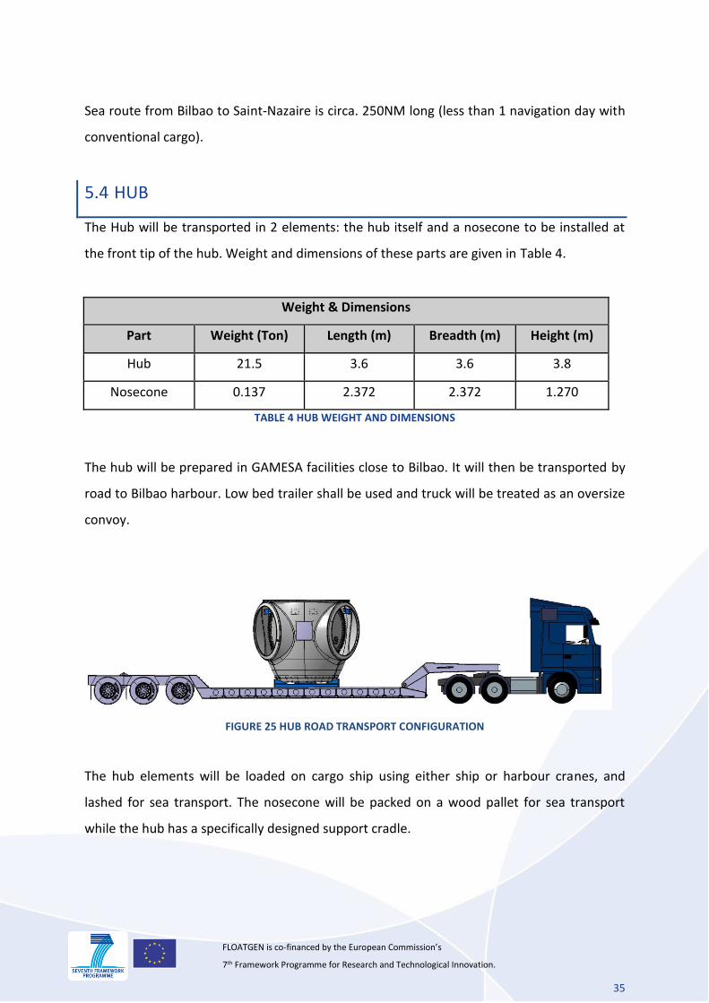
5.4 HUB
The Hub will be transported in 2 elements: the hub itself and a nosecone to be installed at
the front tip of the hub. Weight and dimensions of these parts are given in Table 4.
Weight & Dimensions
Part Weight (Ton) Length (m) Breadth (m) Height (m)
Hub 21.5 3.6 3.6 3.8
Nosecone 0.137 2.372 2.372 1.270
TABLE 4 HUB WEIGHT AND DIMENSIONS
The hub will be prepared in GAMESA facilities close to Bilbao. It will then be transported by
road to Bilbao harbour. Low bed trailer shall be used and truck will be treated as an oversize
convoy.
FIGURE 25 HUB ROAD TRANSPORT CONFIGURATION
The hub elements will be loaded on cargo ship using either ship or harbour cranes, and
lashed for sea transport. The nosecone will be packed on a wood pallet for sea transport
while the hub has a specifically designed support cradle.
36
FLOATGEN is co-financed by the European Commission’s 7th Framework Programme for Research and Technological Innovation.
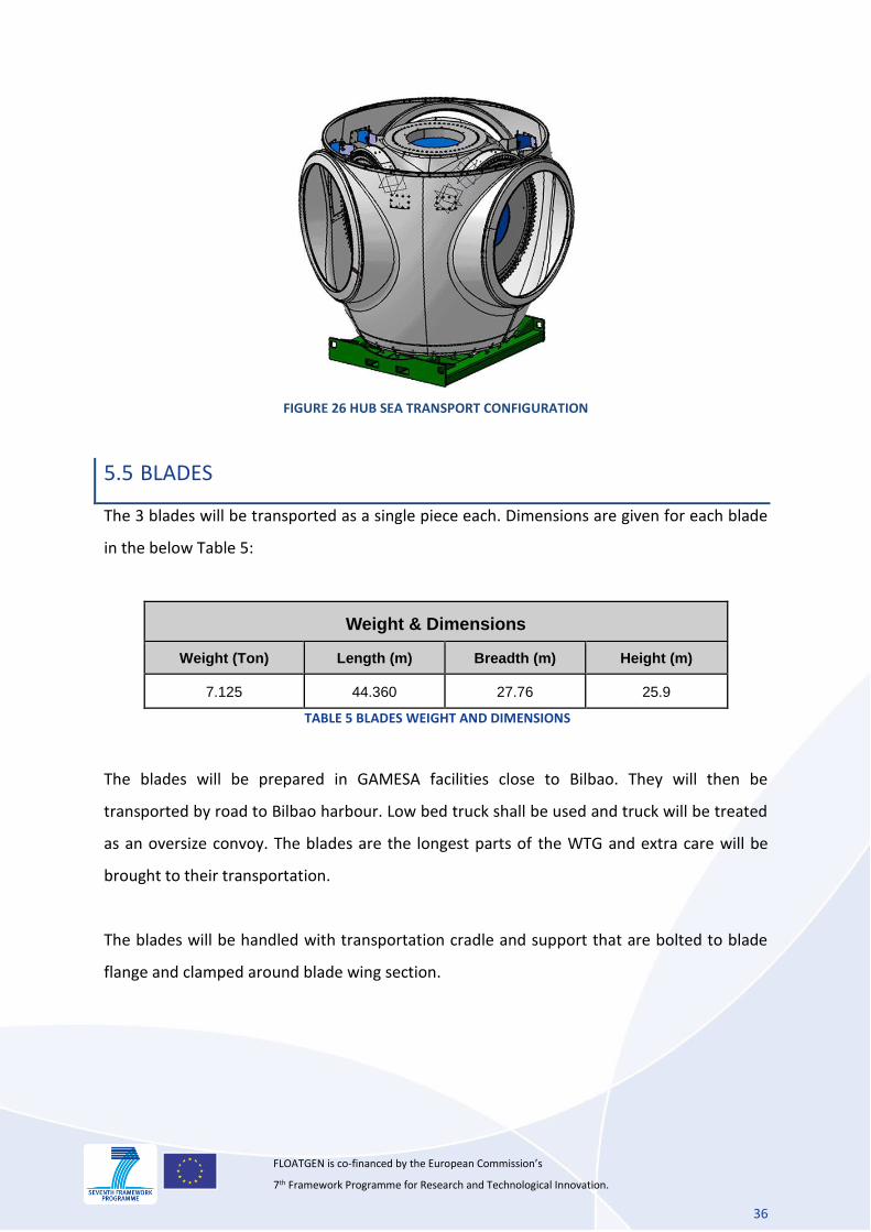
FIGURE 26 HUB SEA TRANSPORT CONFIGURATION
5.5 BLADES
The 3 blades will be transported as a single piece each. Dimensions are given for each blade
in the below Table 5:
Weight & Dimensions Weight (Ton) Length (m) Breadth (m) Height (m)
7.125 44.360 27.76 25.9
TABLE 5 BLADES WEIGHT AND DIMENSIONS
The blades will be prepared in GAMESA facilities close to Bilbao. They will then be
transported by road to Bilbao harbour. Low bed truck shall be used and truck will be treated
as an oversize convoy. The blades are the longest parts of the WTG and extra care will be
brought to their transportation.
The blades will be handled with transportation cradle and support that are bolted to blade
flange and clamped around blade wing section.
37
FLOATGEN is co-financed by the European Commission’s 7th Framework Programme for Research and Technological Innovation.
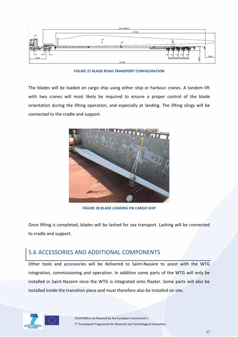
FIGURE 27 BLADE ROAD TRANSPORT CONFIGURATION
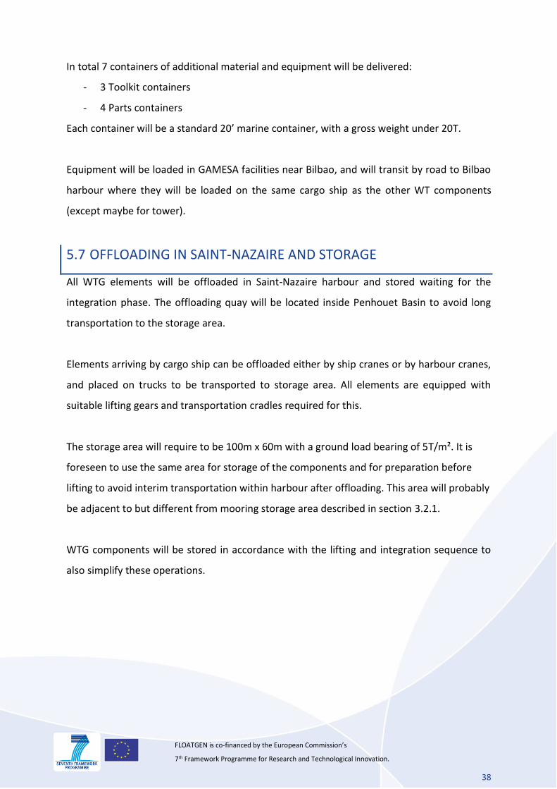
The blades will be loaded on cargo ship using either ship or harbour cranes. A tandem lift
with two cranes will most likely be required to ensure a proper control of the blade
orientation during the lifting operation, and especially at landing. The lifting slings will be
connected to the cradle and support.
FIGURE 28 BLADE LOADING ON CARGO SHIP
Once lifting is completed, blades will be lashed for sea transport. Lashing will be connected
to cradle and support.
5.6 ACCESSORIES AND ADDITIONAL COMPONENTS
Other tools and accessories will be delivered to Saint-Nazaire to assist with the WTG
integration, commissioning and operation. In addition some parts of the WTG will only be
installed in Saint-Nazaire once the WTG is integrated onto floater. Some parts will also be
installed inside the transition piece and must therefore also be installed on site.
38
FLOATGEN is co-financed by the European Commission’s 7th Framework Programme for Research and Technological Innovation.
In total 7 containers of additional material and equipment will be delivered:
- 3 Toolkit containers
- 4 Parts containers
Each container will be a standard 20’ marine container, with a gross weight under 20T.
Equipment will be loaded in GAMESA facilities near Bilbao, and will transit by road to Bilbao
harbour where they will be loaded on the same cargo ship as the other WT components
(except maybe for tower).
5.7 OFFLOADING IN SAINT-NAZAIRE AND STORAGE
All WTG elements will be offloaded in Saint-Nazaire harbour and stored waiting for the
integration phase. The offloading quay will be located inside Penhouet Basin to avoid long
transportation to the storage area.
Elements arriving by cargo ship can be offloaded either by ship cranes or by harbour cranes,
and placed on trucks to be transported to storage area. All elements are equipped with
suitable lifting gears and transportation cradles required for this.
The storage area will require to be 100m x 60m with a ground load bearing of 5T/m². It is
foreseen to use the same area for storage of the components and for preparation before
lifting to avoid interim transportation within harbour after offloading. This area will probably
be adjacent to but different from mooring storage area described in section 3.2.1.
WTG components will be stored in accordance with the lifting and integration sequence to
also simplify these operations.
39
FLOATGEN is co-financed by the European Commission’s 7th Framework Programme for Research and Technological Innovation.
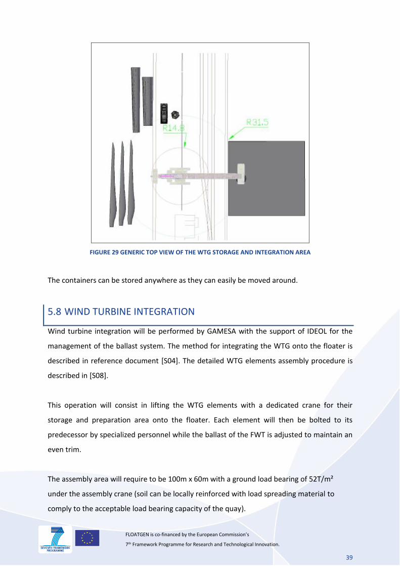
FIGURE 29 GENERIC TOP VIEW OF THE WTG STORAGE AND INTEGRATION AREA
The containers can be stored anywhere as they can easily be moved around.
5.8 WIND TURBINE INTEGRATION
Wind turbine integration will be performed by GAMESA with the support of IDEOL for the
management of the ballast system. The method for integrating the WTG onto the floater is
described in reference document [S04]. The detailed WTG elements assembly procedure is
described in [S08].
This operation will consist in lifting the WTG elements with a dedicated crane for their
storage and preparation area onto the floater. Each element will then be bolted to its
predecessor by specialized personnel while the ballast of the FWT is adjusted to maintain an
even trim.
The assembly area will require to be 100m x 60m with a ground load bearing of 52T/m²
under the assembly crane (soil can be locally reinforced with load spreading material to
comply to the acceptable load bearing capacity of the quay).
40
FLOATGEN is co-financed by the European Commission’s 7th Framework Programme for Research and Technological Innovation.
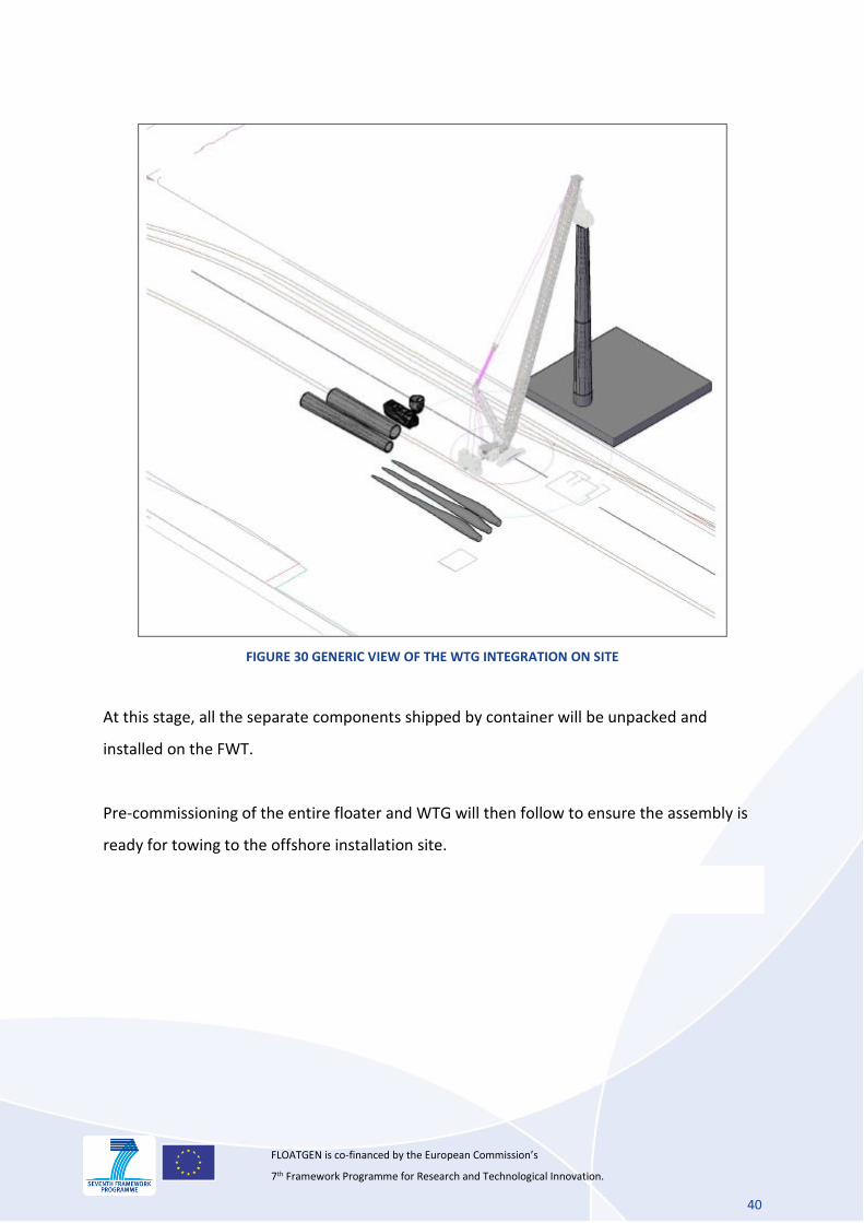
FIGURE 30 GENERIC VIEW OF THE WTG INTEGRATION ON SITE
At this stage, all the separate components shipped by container will be unpacked and
installed on the FWT.
Pre-commissioning of the entire floater and WTG will then follow to ensure the assembly is
ready for towing to the offshore installation site.
41
FLOATGEN is co-financed by the European Commission’s 7th Framework Programme for Research and Technological Innovation.
6. FLOATING WIND TURBINE TOWING
FWT towing at sea will be subcontracted to a specialized company. A Marine Warranty
Surveyor, working on behalf of the CAR insurer, will be contracted for marine survey prior to
the departure (work procedures and towing survey). A MWS Representative will attend the
tow with offshore personnel on board the towing tug.
FWT towing is divided in two different phases: the harbour tow and the seagoing tow.
Configuration for harbour tow is a rigid convoy (tugs in contact with the FWT), configuration
for the open sea towing is more classical (two tugs in the bow and one single tug at the aft
with towing chains and wire). Both arrangements are outlined in the following sections.
It is likely that the overall towing will be done by BOLUDA, the Tow Contractor of the Port of
Saint-Nazaire.
6.1 AUTHORIZATION
The following administrative procedures have to be taken prior to the tow:
Airfield licence: project must meet the requirements of the civil and military Agencies for
safety during transport to offshore site.
Maritime Transport Licence: the project must meet the requirements of the Maritime &
Coastguard Agency and other regulatory requirements for navigational safety during
transport to site.
Prevention Plan: This document must be agreed and signed prior to the deployment.
Coast Guards (CROSS): Notice to Coast Guards shall be done with sufficient delay
Port Pilotage: Pilotage is part of the tow (harbour part)
Insurance: Insurance scheme with tow Contractor for the FWT must be finalized.
In addition a Marine Warranty Surveyor will be implicated in the marine spread mobilization
and sea fastening prior to the departure and will issue a Certificate of approval when
procedure will be approved. Noble Denton guidelines [R02] as well as IMO rules [R03] and
SOLAS [R01]will be used as standards for the ocean tow works.
6.2 PORT AVAILABLE FLEET
42
FLOATGEN is co-financed by the European Commission’s 7th Framework Programme for Research and Technological Innovation.
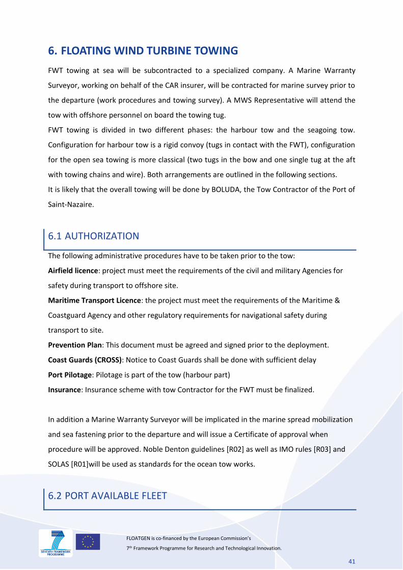
BOLUDA is the towing Contractor of Saint-Nazaire Port whose fleet is composed of:
Vessel Type Displacement
CROISIC
Azimuth Stern Drive 60 T 620 T
VB POULIGUEN
Azimuth Tractor 40 T 353 T
VB NANTES
Azimuth Stern Drive 60 T 389 T UMS
VB BRETAGNE
Azimuth Stern Drive 60 T 389 T UMS
GUERANDE
Azimuth Tractor 40 T 353 T
ST MARC
Azimuth Tractor 38 T 445 T
PORNICHET
Azimuth Tractor 38 T 353 T
ST BREVIN
Azimuth Tractor 38 T 445 T
TABLE 6 AVAILABLE TUGS IN SAINT-NAZAIRE
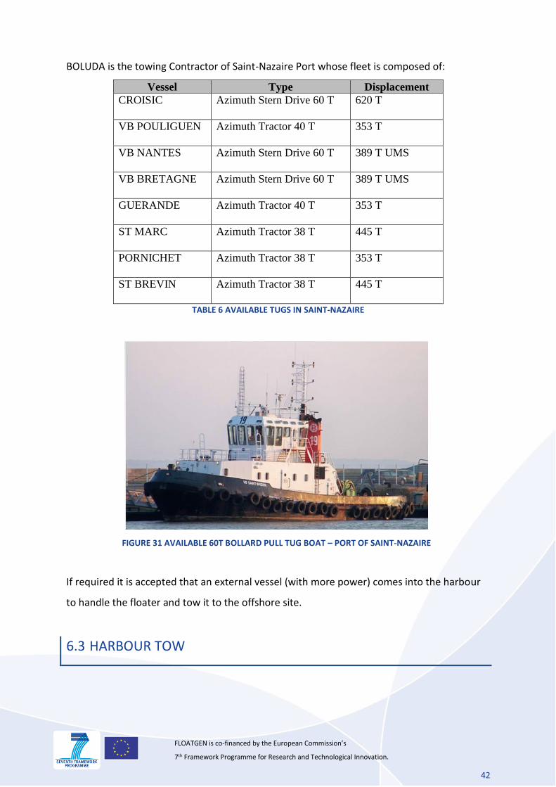
FIGURE 31 AVAILABLE 60T BOLLARD PULL TUG BOAT – PORT OF SAINT-NAZAIRE
If required it is accepted that an external vessel (with more power) comes into the harbour
to handle the floater and tow it to the offshore site.
6.3 HARBOUR TOW
43
FLOATGEN is co-financed by the European Commission’s 7th Framework Programme for Research and Technological Innovation.
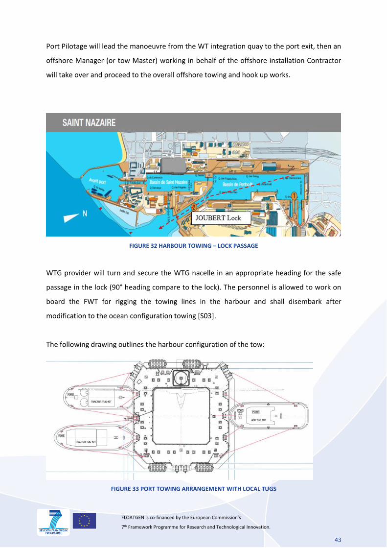
Port Pilotage will lead the manoeuvre from the WT integration quay to the port exit, then an
offshore Manager (or tow Master) working in behalf of the offshore installation Contractor
will take over and proceed to the overall offshore towing and hook up works.
FIGURE 32 HARBOUR TOWING – LOCK PASSAGE
WTG provider will turn and secure the WTG nacelle in an appropriate heading for the safe
passage in the lock (90° heading compare to the lock). The personnel is allowed to work on
board the FWT for rigging the towing lines in the harbour and shall disembark after
modification to the ocean configuration towing [S03].
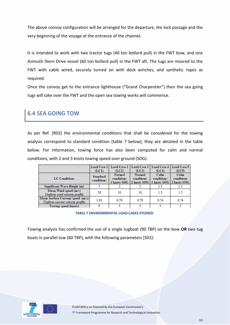
The following drawing outlines the harbour configuration of the tow:
FIGURE 33 PORT TOWING ARRANGEMENT WITH LOCAL TUGS
44
FLOATGEN is co-financed by the European Commission’s 7th Framework Programme for Research and Technological Innovation.
The above convoy configuration will be arranged for the departure, the lock passage and the
very beginning of the voyage at the entrance of the channel.
It is intended to work with two tractor tugs (40 ton bollard pull) in the FWT bow, and one
Azimuth Stern Drive vessel (60 ton bollard pull) in the FWT aft. The tugs are moored to the
FWT with cable wired, securely turned on with deck winches, and synthetic ropes as
required.
Once the convoy get to the entrance lighthouse (“Grand Charpentier”) then the sea going
tugs will take over the FWT and the open sea towing works will commence.
6.4 SEA GOING TOW
As per Ref. [R02] the environmental conditions that shall be considered for the towing
analysis correspond to standard condition (table 7 below); they are detailed in the table
below. For information, towing force has also been computed for calm and normal
conditions, with 2 and 3 knots towing speed over ground (SOG).
TABLE 7 ENVIRONMENTAL LOAD CASES STUDIED
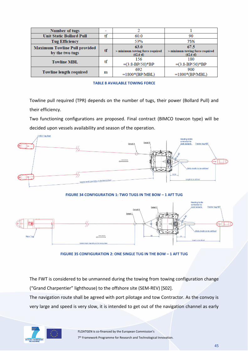
Towing analysis has confirmed the use of a single tugboat (90 TBP) on the bow OR two tug
boats in parallel tow (60 TBP), with the following parameters [S01]:
45
FLOATGEN is co-financed by the European Commission’s 7th Framework Programme for Research and Technological Innovation.
TABLE 8 AVAILABLE TOWING FORCE
Towline pull required (TPR) depends on the number of tugs, their power (Bollard Pull) and
their efficiency.
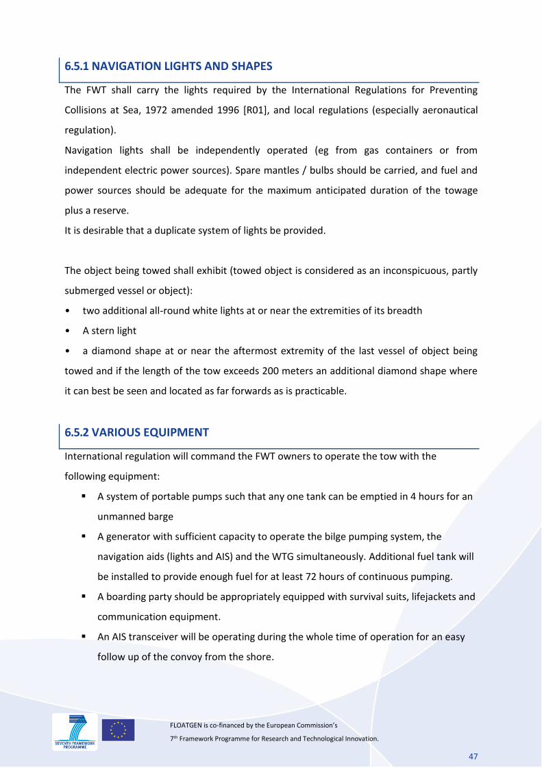
Two functioning configurations are proposed. Final contract (BIMCO towcon type) will be
decided upon vessels availability and season of the operation.
FIGURE 34 CONFIGURATION 1: TWO TUGS IN THE BOW – 1 AFT TUG
FIGURE 35 CONFIGURATION 2: ONE SINGLE TUG IN THE BOW – 1 AFT TUG
The FWT is considered to be unmanned during the towing from towing configuration change
(“Grand Charpentier” lighthouse) to the offshore site (SEM-REV) [S02].
The navigation route shall be agreed with port pilotage and tow Contractor. As the convoy is
very large and speed is very slow, it is intended to get out of the navigation channel as early

46
FLOATGEN is co-financed by the European Commission’s 7th Framework Programme for Research and Technological Innovation.
as possible, upon Pilotage proposal. Sailing out of the channel will avoid any risk of
interference with regular navigation.
FIGURE 36
RED ROUTE: REGULAR NAVIGATION ROUTE THROUGH PORT CHANNEL
YELLOW ROUTE: PROPOSED ROUTE TO THE OFFSHORE SITE OUT OF THE CHANNEL
The proposed route (yellow drawing) is 29 nm (or 15 hours @ 2 kts SOG), which is a sensible
reduction of transit time that is taken out from the favourable weather window. Alternately
the channel navigation route is 40 nm (20 hours @ 2 kts SOG).
6.5 SPECIAL EQUIPMENT FOR THE TOW
A set of equipment will be mobilized on board the FWT for the safe towing from Saint-
Nazaire to the installation site. The towing works shall be compliant with the international
standards [R01][R02][R03] and validated by MWS.
47
FLOATGEN is co-financed by the European Commission’s 7th Framework Programme for Research and Technological Innovation.
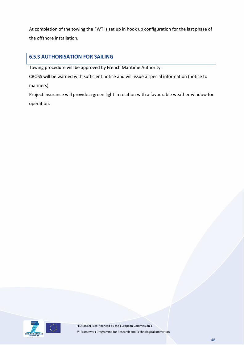
6.5.1 NAVIGATION LIGHTS AND SHAPES
The FWT shall carry the lights required by the International Regulations for Preventing
Collisions at Sea, 1972 amended 1996 [R01], and local regulations (especially aeronautical
regulation).
Navigation lights shall be independently operated (eg from gas containers or from
independent electric power sources). Spare mantles / bulbs should be carried, and fuel and
power sources should be adequate for the maximum anticipated duration of the towage
plus a reserve.
It is desirable that a duplicate system of lights be provided.
The object being towed shall exhibit (towed object is considered as an inconspicuous, partly
submerged vessel or object):
• two additional all-round white lights at or near the extremities of its breadth
• A stern light
• a diamond shape at or near the aftermost extremity of the last vessel of object being
towed and if the length of the tow exceeds 200 meters an additional diamond shape where
it can best be seen and located as far forwards as is practicable.
6.5.2 VARIOUS EQUIPMENT
International regulation will command the FWT owners to operate the tow with the
following equipment:
A system of portable pumps such that any one tank can be emptied in 4 hours for an
unmanned barge
A generator with sufficient capacity to operate the bilge pumping system, the
navigation aids (lights and AIS) and the WTG simultaneously. Additional fuel tank will
be installed to provide enough fuel for at least 72 hours of continuous pumping.
A boarding party should be appropriately equipped with survival suits, lifejackets and
communication equipment.
An AIS transceiver will be operating during the whole time of operation for an easy
follow up of the convoy from the shore.
48
FLOATGEN is co-financed by the European Commission’s 7th Framework Programme for Research and Technological Innovation.
At completion of the towing the FWT is set up in hook up configuration for the last phase of
the offshore installation.
6.5.3 AUTHORISATION FOR SAILING
Towing procedure will be approved by French Maritime Authority.
CROSS will be warned with sufficient notice and will issue a special information (notice to
mariners).
Project insurance will provide a green light in relation with a favourable weather window for
operation.