floe dock furniture - floe international incorporated€¦ · your furniture is now complete. grab...
TRANSCRIPT
Page 1
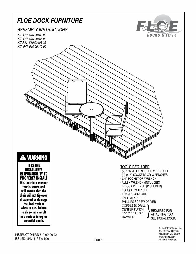
FLOE DOCK FURNITUREASSEMBLY INSTRUCTIONSKIT P/N 510-00400-02KIT P/N 510-00405-02KIT P/N 510-00406-02KIT P/N 510-00410-02
©Floe International, Inc.48473 State Hwy. 65McGregor, MN 55760www.floeintl.comAll rights reserved.
INSTRUCTION P/N 610-00400-02ISSUED: 5/7/15 REV: 1/20
TOOLS REQUIRED• (2) 13MM SOCKETS OR WRENCHES• (2) 9/16” SOCKETS OR WRENCHES• 3/4” SOCKET OR WRENCH• ALLEN WRENCH (INCLUDED)• T-ROCK WRENCH (INCLUDED)• TORQUE WRENCH• FRAMING SQUARE• TAPE MEASURE• PHILLIPS SCREW DRIVER• CORDLESS DRILL• CENTER PUNCH• 13/32” DRILL BIT• HAMMER
REQUIRED FOR ATTACHING TO A SECTIONAL DOCK.
IT IS THE INSTALLER’S
RESPONSIBILITY TO PROPERLY INSTALLthis chair in a manner
that is secure and will ensure that the
chair will not tip over, disconnect or damage
the dock system when in use. Failure to do so may result
in a serious injury or potential death.
WARNING
Page 2
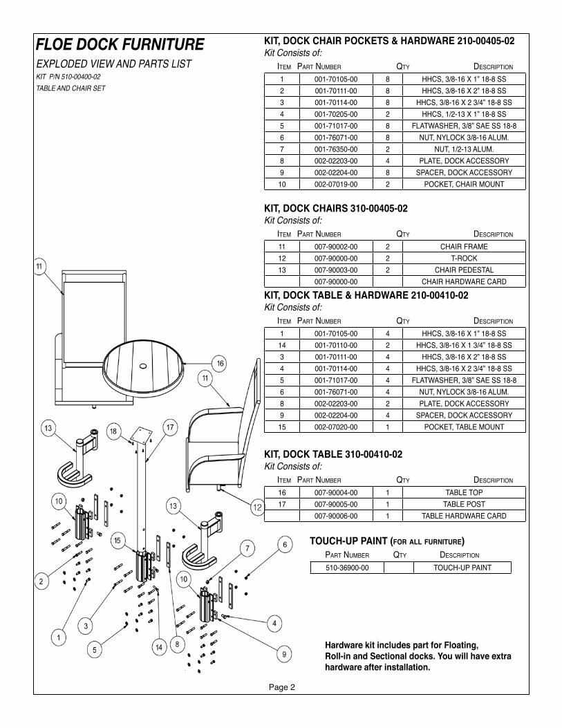
FLOE DOCK FURNITUREEXPLODED VIEW AND PARTS LISTKIT P/N 510-00400-02TABLE AND CHAIR SET
Hardware kit includes part for Floating, Roll-in and Sectional docks. You will have extra hardware after installation.
1 001-70105-00 8 HHCS, 3/8-16 X 1” 18-8 SS2 001-70111-00 8 HHCS, 3/8-16 X 2” 18-8 SS3 001-70114-00 8 HHCS, 3/8-16 X 2 3/4” 18-8 SS4 001-70205-00 2 HHCS, 1/2-13 X 1” 18-8 SS5 001-71017-00 8 FLATWASHER, 3/8” SAE SS 18-86 001-76071-00 8 NUT, NYLOCK 3/8-16 ALUM.7 001-76350-00 2 NUT, 1/2-13 ALUM.8 002-02203-00 4 PLATE, DOCK ACCESSORY9 002-02204-00 8 SPACER, DOCK ACCESSORY
10 002-07019-00 2 POCKET, CHAIR MOUNT
KIT, DOCK CHAIR POCKETS & HARDWARE 210-00405-02Kit Consists of: Item Part Number Qty DescrIPtIoN
11 007-90002-00 2 CHAIR FRAME12 007-90000-00 2 T-ROCK13 007-90003-00 2 CHAIR PEDESTAL
007-90000-00 CHAIR HARDWARE CARD
KIT, DOCK CHAIRS 310-00405-02Kit Consists of: Item Part Number Qty DescrIPtIoN
1 001-70105-00 4 HHCS, 3/8-16 X 1” 18-8 SS14 001-70110-00 2 HHCS, 3/8-16 X 1 3/4” 18-8 SS3 001-70111-00 4 HHCS, 3/8-16 X 2” 18-8 SS4 001-70114-00 4 HHCS, 3/8-16 X 2 3/4” 18-8 SS5 001-71017-00 4 FLATWASHER, 3/8” SAE SS 18-86 001-76071-00 4 NUT, NYLOCK 3/8-16 ALUM.8 002-02203-00 2 PLATE, DOCK ACCESSORY9 002-02204-00 4 SPACER, DOCK ACCESSORY
15 002-07020-00 1 POCKET, TABLE MOUNT
KIT, DOCK TABLE & HARDWARE 210-00410-02Kit Consists of: Item Part Number Qty DescrIPtIoN
16 007-90004-00 1 TABLE TOP17 007-90005-00 1 TABLE POST
007-90006-00 1 TABLE HARDWARE CARD
KIT, DOCK TABLE 310-00410-02Kit Consists of: Item Part Number Qty DescrIPtIoN
TOUCH-UP PAINT (for all furniture) Part Number Qty DescrIPtIoN
510-36900-00 TOUCH-UP PAINT
Page 3
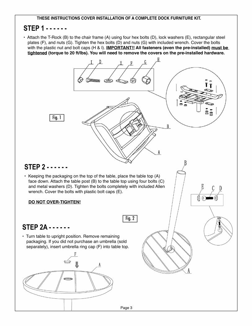
STEP 1 - - - - - -• Attach the T-Rock (B) to the chair frame (A) using four hex bolts (D), lock washers (E), rectangular steel
plates (F), and nuts (G). Tighten the hex bolts (D) and nuts (G) with included wrench. Cover the bolts with the plastic nut and bolt caps (H & I). IMPORTANT!! All fasteners (even the pre-installed) must be tightened (torque to 20 ft/lbs). You will need to remove the covers on the pre-installed hardware.
Fig. 1
Fig. 2
THESE INSTRUCTIONS COVER INSTALLATION OF A COMPLETE DOCK FURNITURE KIT.
STEP 2A - - - - - -• Turn table to upright position. Remove remaining
packaging. If you did not purchase an umbrella (sold separately), insert umbrella ring cap (F) into table top.
STEP 2 - - - - - -• Keeping the packaging on the top of the table, place the table top (A)
face down. Attach the table post (B) to the table top using four bolts (C) and metal washers (D). Tighten the bolts completely with included Allen wrench. Cover the bolts with plastic bolt caps (E).
DO NOT OVER-TIGHTEN!
Page 4
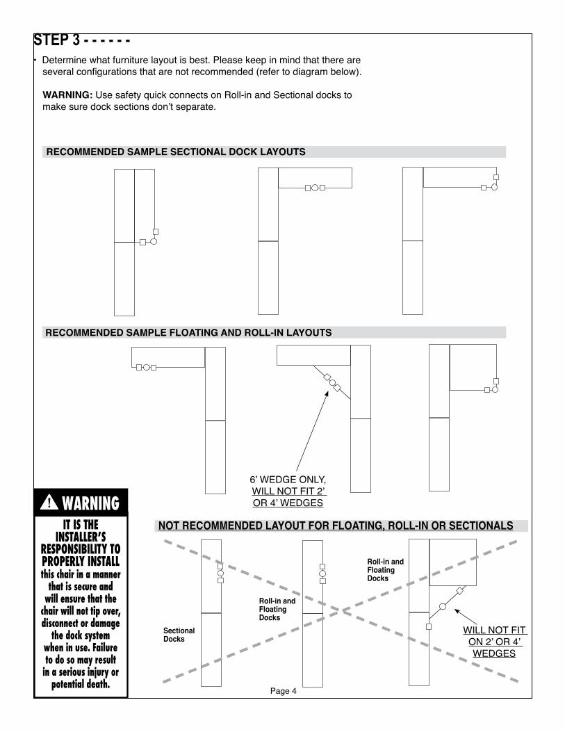
STEP 3 - - - - - -• Determine what furniture layout is best. Please keep in mind that there are
several configurations that are not recommended (refer to diagram below).
WARNING: Use safety quick connects on Roll-in and Sectional docks to make sure dock sections don’t separate.
IT IS THE INSTALLER’S
RESPONSIBILITY TO PROPERLY INSTALLthis chair in a manner
that is secure and will ensure that the
chair will not tip over, disconnect or damage
the dock system when in use. Failure to do so may result
in a serious injury or potential death.
WARNING6’ WEDGE ONLY,WILL NOT FIT 2’ OR 4’ WEDGES
RECOMMENDED SAMPLE FLOATING AND ROLL-IN LAYOUTS
RECOMMENDED SAMPLE SECTIONAL DOCK LAYOUTS
NOT RECOMMENDED LAYOUT FOR FLOATING, ROLL-IN OR SECTIONALS
SectionalDocks
Roll-in andFloatingDocks
Roll-in andFloatingDocks
WILL NOT FIT ON 2’ OR 4’ WEDGES
Page 5
NOTE: If installing only chairs and no table, they must be mounted a minimum of 30” apart (center of pocket to center of pocket). Table kit pockets must be mounted a minimum of 31” from a chair pocket.
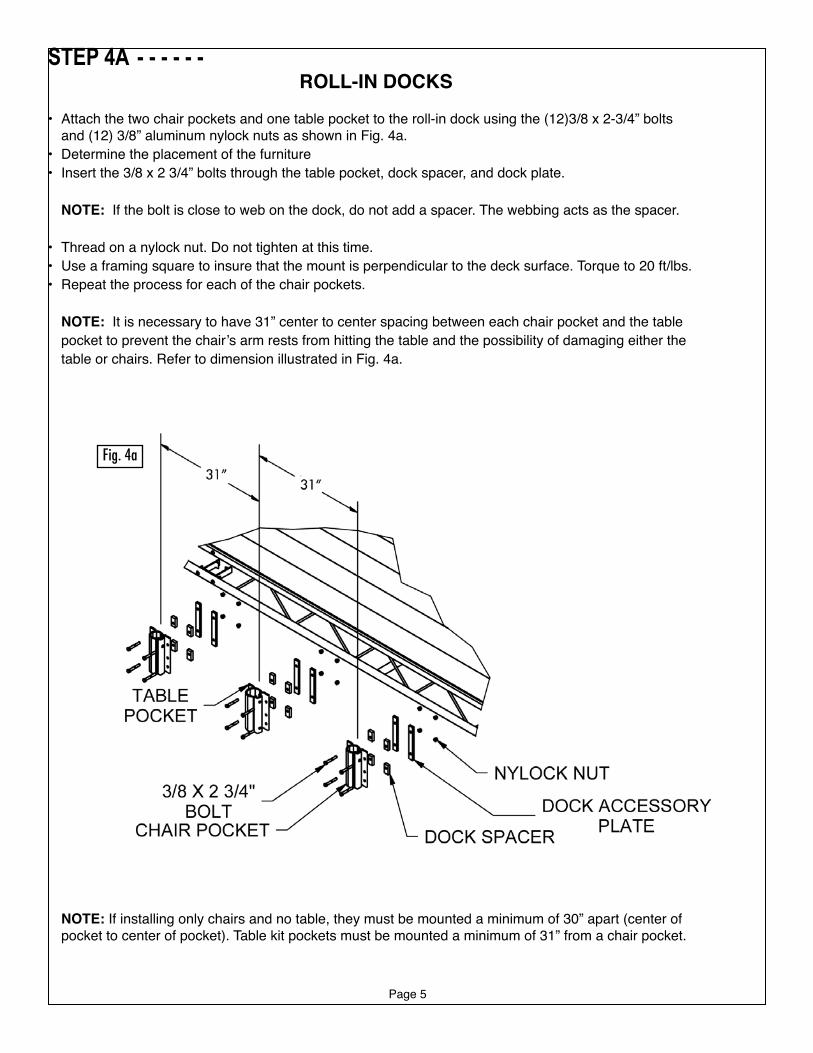
STEP 4A - - - - - -ROLL-IN DOCKS
• Attach the two chair pockets and one table pocket to the roll-in dock using the (12)3/8 x 2-3/4” bolts and (12) 3/8” aluminum nylock nuts as shown in Fig. 4a.
• Determine the placement of the furniture• Insert the 3/8 x 2 3/4” bolts through the table pocket, dock spacer, and dock plate.
NOTE: If the bolt is close to web on the dock, do not add a spacer. The webbing acts as the spacer.
• Thread on a nylock nut. Do not tighten at this time. • Use a framing square to insure that the mount is perpendicular to the deck surface. Torque to 20 ft/lbs. • Repeat the process for each of the chair pockets.
NOTE: It is necessary to have 31” center to center spacing between each chair pocket and the table pocket to prevent the chair’s arm rests from hitting the table and the possibility of damaging either the table or chairs. Refer to dimension illustrated in Fig. 4a.
Fig. 4a
Page 6
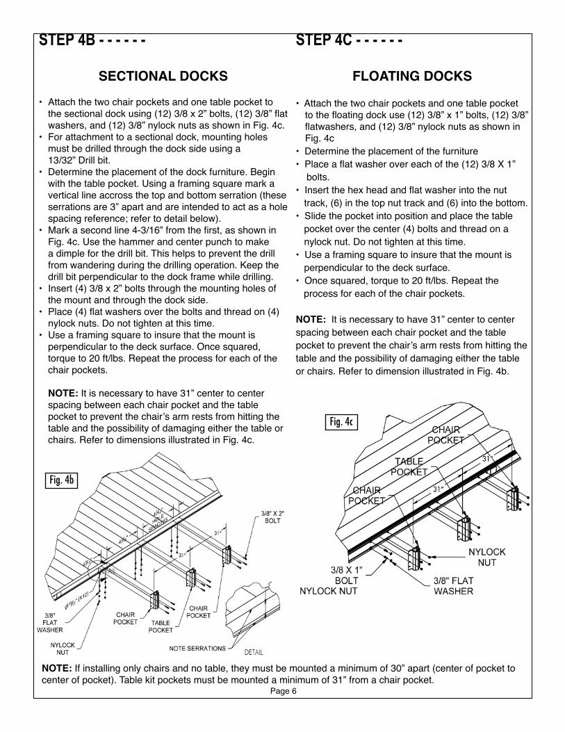
STEP 4C - - - - - -
FLOATING DOCKS
• Attach the two chair pockets and one table pocket to the floating dock use (12) 3/8” x 1” bolts, (12) 3/8” flatwashers, and (12) 3/8” nylock nuts as shown in Fig. 4c
• Determine the placement of the furniture• Place a flat washer over each of the (12) 3/8 X 1” bolts. • Insert the hex head and flat washer into the nut
track, (6) in the top nut track and (6) into the bottom. • Slide the pocket into position and place the table
pocket over the center (4) bolts and thread on a nylock nut. Do not tighten at this time.
• Use a framing square to insure that the mount is perpendicular to the deck surface.
• Once squared, torque to 20 ft/lbs. Repeat the process for each of the chair pockets.
NOTE: It is necessary to have 31” center to center spacing between each chair pocket and the table pocket to prevent the chair’s arm rests from hitting the table and the possibility of damaging either the table or chairs. Refer to dimension illustrated in Fig. 4b.
Fig. 4b
STEP 4B - - - - - -
SECTIONAL DOCKS
• Attach the two chair pockets and one table pocket to the sectional dock using (12) 3/8 x 2” bolts, (12) 3/8” flat washers, and (12) 3/8” nylock nuts as shown in Fig. 4c.
• For attachment to a sectional dock, mounting holes must be drilled through the dock side using a 13/32” Drill bit.
• Determine the placement of the dock furniture. Begin with the table pocket. Using a framing square mark a vertical line accross the top and bottom serration (these serrations are 3” apart and are intended to act as a hole spacing reference; refer to detail below).
• Mark a second line 4-3/16” from the first, as shown in Fig. 4c. Use the hammer and center punch to make a dimple for the drill bit. This helps to prevent the drill from wandering during the drilling operation. Keep the drill bit perpendicular to the dock frame while drilling.
• Insert (4) 3/8 x 2” bolts through the mounting holes of the mount and through the dock side.
• Place (4) flat washers over the bolts and thread on (4) nylock nuts. Do not tighten at this time.
• Use a framing square to insure that the mount is perpendicular to the deck surface. Once squared, torque to 20 ft/lbs. Repeat the process for each of the chair pockets.
NOTE: It is necessary to have 31” center to center spacing between each chair pocket and the table pocket to prevent the chair’s arm rests from hitting the table and the possibility of damaging either the table or chairs. Refer to dimensions illustrated in Fig. 4c.
Fig. 4c
NOTE: If installing only chairs and no table, they must be mounted a minimum of 30” apart (center of pocket to center of pocket). Table kit pockets must be mounted a minimum of 31” from a chair pocket.
Page 7
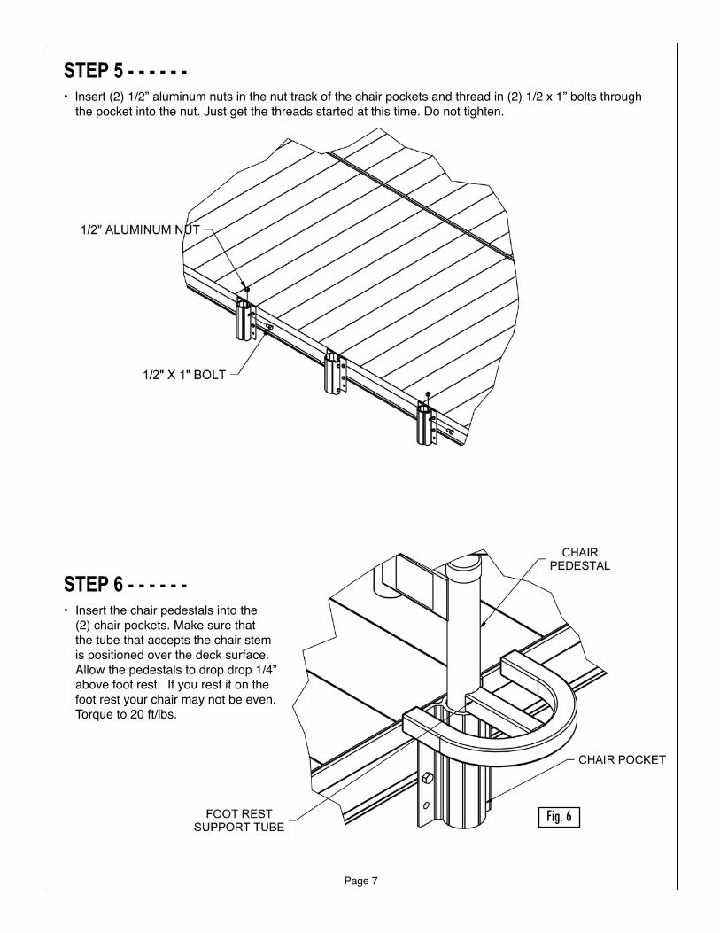
STEP 5 - - - - - -• Insert (2) 1/2” aluminum nuts in the nut track of the chair pockets and thread in (2) 1/2 x 1” bolts through
the pocket into the nut. Just get the threads started at this time. Do not tighten.
STEP 6 - - - - - -• Insert the chair pedestals into the
(2) chair pockets. Make sure that the tube that accepts the chair stem is positioned over the deck surface. Allow the pedestals to drop drop 1/4” above foot rest. If you rest it on the foot rest your chair may not be even. Torque to 20 ft/lbs.
Fig. 6
Fig. 5
Page 8
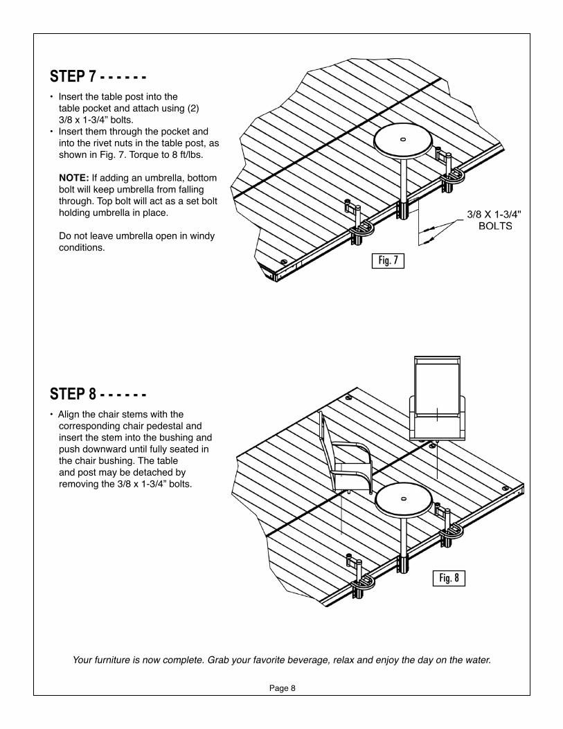
STEP 7 - - - - - -• Insert the table post into the table pocket and attach using (2) 3/8 x 1-3/4” bolts. • Insert them through the pocket and
into the rivet nuts in the table post, as shown in Fig. 7. Torque to 8 ft/lbs.
NOTE: If adding an umbrella, bottom bolt will keep umbrella from falling through. Top bolt will act as a set bolt holding umbrella in place.
Do not leave umbrella open in windy conditions.
STEP 8 - - - - - -• Align the chair stems with the
corresponding chair pedestal and insert the stem into the bushing and push downward until fully seated in the chair bushing. The table
and post may be detached by removing the 3/8 x 1-3/4” bolts.
Fig. 7
Fig. 8
Your furniture is now complete. Grab your favorite beverage, relax and enjoy the day on the water.
Page 9
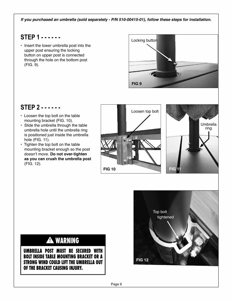
STEP 1 - - - - - -• Insert the lower umbrella post into the
upper post ensuring the locking button on upper post is connected through the hole on the bottom post (FIG. 9).
STEP 2 - - - - - -• Loosen the top bolt on the table
mounting bracket (FIG. 10). • Slide the umbrella through the table
umbrella hole until the umbrella ring is positioned just inside the umbrella hole (FIG. 11).
• Tighten the top bolt on the table mounting bracket enough so the post doesn’t move. Do not over-tighten as you can crush the umbrella post (FIG. 12).
UMBRELLA POST MUST BE SECURED WITH BOLT INSIDE TABLE MOUNTING BRACKET OR A STRONG WIND COULD LIFT THE UMBRELLA OUT OF THE BRACKET CAUSING INJURY.
WARNING
FIG 9
FIG 12
FIG 10
Loosen top bolt
Top bolt tightened
Locking button
If you purchased an umbrella (sold separately - P/N 510-00415-01), follow these steps for installation.
FIG 11
Umbrella ring

Page 10

Page 11

Page 12